JP4150591B2 - How to extract a variable reference pattern - Google Patents
How to extract a variable reference pattern Download PDFInfo
- Publication number
- JP4150591B2 JP4150591B2 JP2002564876A JP2002564876A JP4150591B2 JP 4150591 B2 JP4150591 B2 JP 4150591B2 JP 2002564876 A JP2002564876 A JP 2002564876A JP 2002564876 A JP2002564876 A JP 2002564876A JP 4150591 B2 JP4150591 B2 JP 4150591B2
- Authority
- JP
- Japan
- Prior art keywords
- reference pattern
- channel
- frequency
- transmission channel
- signal
- Prior art date
- Legal status (The legal status is an assumption and is not a legal conclusion. Google has not performed a legal analysis and makes no representation as to the accuracy of the status listed.)
- Expired - Fee Related
Links
Images


Classifications
-
- H—ELECTRICITY
- H04—ELECTRIC COMMUNICATION TECHNIQUE
- H04B—TRANSMISSION
- H04B7/00—Radio transmission systems, i.e. using radiation field
- H04B7/24—Radio transmission systems, i.e. using radiation field for communication between two or more posts
- H04B7/26—Radio transmission systems, i.e. using radiation field for communication between two or more posts at least one of which is mobile
-
- H—ELECTRICITY
- H04—ELECTRIC COMMUNICATION TECHNIQUE
- H04L—TRANSMISSION OF DIGITAL INFORMATION, e.g. TELEGRAPHIC COMMUNICATION
- H04L1/00—Arrangements for detecting or preventing errors in the information received
- H04L1/0001—Systems modifying transmission characteristics according to link quality, e.g. power backoff
- H04L1/0006—Systems modifying transmission characteristics according to link quality, e.g. power backoff by adapting the transmission format
- H04L1/0007—Systems modifying transmission characteristics according to link quality, e.g. power backoff by adapting the transmission format by modifying the frame length
Description
本発明は、ディジタルデータを送信する分野に関する。より正確には、本発明は送信チャネルの伝達関数を評価すること、及びこのチャネルを使用する無線通信装置の同期を維持しながら遠隔ステーションとディジタルデータを交換することに関する。 The present invention relates to the field of transmitting digital data. More precisely, the present invention relates to evaluating the transfer function of a transmission channel and exchanging digital data with a remote station while maintaining the synchronization of wireless communication devices using this channel.
従来のディジタル通信システムでは、基準記号又はパイロット記号と呼ばれる、受信機には周知の一連の基準記号は、送信機によって送られたデータストリームの中で使用されることが多い。これらの基準記号により、受信機は送信チャネルを適当に評価することができ、これにより、受信された信号が適切に復調されることが保証される。 In conventional digital communication systems, a series of reference symbols known to the receiver, called reference symbols or pilot symbols, are often used in the data stream sent by the transmitter. These reference symbols allow the receiver to properly evaluate the transmission channel, thereby ensuring that the received signal is properly demodulated.
時間が可変の送信チャネルを含む通信システムについては、基準記号を交換されたデータストリーム内の異なる位置に配置すると認識されてきた。 For communication systems that include variable time transmission channels, it has been recognized that the reference symbols are located at different locations within the exchanged data streams.
これらの各種の通信システムでは、無線通信装置の基準記号の構造及び特性は、伝搬が最悪の場合の関数として決定される。この種の制約は、伝搬状態にかかわらず、正確なチャネル評価を行うために不可欠である。 In these various communication systems, the structure and characteristics of the reference symbols of the wireless communication device are determined as a function of worst case propagation. This type of constraint is essential for accurate channel estimation regardless of propagation conditions.
初期の同期化段階が完了すると、専用のリソースが無線通信端末に割り当てられ、次に、必要な場合、それは同期保持段階を実行して、送信チャネルの評価を行う。 When the initial synchronization phase is complete, dedicated resources are allocated to the wireless communication terminal, which then performs a synchronization hold phase to evaluate the transmission channel, if necessary.
この従来技術によれば、基準構造は、全ての場合において、またさらに最悪の通信状態においても、言い換えると対象となる通信端末の最大のマルチパスレベル(multipath level)及び最大速度に対しても、正確なチャネル評価をできるように選択される。 According to this prior art, the reference structure is in all cases and even in the worst communication state, in other words for the maximum multipath level and maximum speed of the target communication terminal, Selected for accurate channel assessment.
換言すると、基準構造は、最悪のドップラ状態及び最悪の遅延スプレッド(delay spread)に適合した大きさを持つ。 In other words, the reference structure has a size adapted to the worst Doppler state and the worst delay spread.
最悪な状態に対して基準構造の大きさを決める欠点は、送信チャネルの特性が良好な場合に、それが有用な送信能力及び/又はエラーに対する保護の統計的な損失をもたらすことである。 The drawback of determining the size of the reference structure for the worst case is that it provides a useful loss of transmission capability and / or statistical loss of protection against errors when the transmission channel is good.
発明者らは、この問題を発見し分析してきた。発明者らは、従来技術に基づくこの技術の欠点は、基準構造が所定の物理的な送信チャネルに対して一度だけ凍結されることであると推論した。 The inventors have discovered and analyzed this problem. The inventors reasoned that the drawback of this technique based on the prior art is that the reference structure is frozen only once for a given physical transmission channel.
その結果、従来技術によるこの技術の別の欠点は、基準記号の選択された順序は、対象となる通信端末の環境に部分的に依存する通信チャネルの特性、及びこの端末の置換速度にも依存しないことである。 As a result, another disadvantage of this technique according to the prior art is that the selected order of the reference symbols depends also on the characteristics of the communication channel that depends in part on the environment of the target communication terminal and on the replacement speed of this terminal. Is not to.
基準構造は最悪の信号伝搬状態に適合されているため、良好なチャネル評価を得るために、基準構造を固定し固有にすべきであると最近では常に考えられているので、この問題を簡単に述べることは当業者には新規で創意に富んでいることに注意されたい。 Since the reference structure is adapted to the worst signal propagation conditions, it is now always considered that the reference structure should be fixed and unique in order to obtain a good channel estimate. It should be noted that what is described is novel and inventive to those skilled in the art.
このため、本発明の目的は、従来技術によるこれらの欠点を克服することである。 The object of the present invention is therefore to overcome these drawbacks according to the prior art.
より正確には、本発明の目的は、無線通信装置と遠隔ステーションとの間の、特に、これに限定されることはないが、マルチキャリアシステム(multi-carrier system)における有用なディジタルデータの送信フローを最適化することである。 More precisely, the object of the present invention is to transmit useful digital data between a wireless communication device and a remote station, in particular, but not exclusively, in a multi-carrier system. It is to optimize the flow.
本発明の別の目的は、スペクトル効率が高い通信システム、特に、無線通信システムを実現することである。 Another object of the present invention is to realize a communication system with high spectral efficiency, in particular a wireless communication system.
本発明の別の目的は、ディジタルデータの品質と通信速度との間の望ましい妥協を作り出す通信システムを提供することである。 Another object of the present invention is to provide a communication system that creates the desired compromise between digital data quality and communication speed.
本発明の別の目的は、チャネルの特性が良好な場合、有効な送信能力の損失を押さえる無線通信システムを実現することである。 Another object of the present invention is to realize a wireless communication system that suppresses the loss of effective transmission capability when channel characteristics are good.
本発明の別の目的は、対象の送信チャネルが乱されている場合でさえ、チャネルの伝達関数を良好に評価できるようにすることである。 Another object of the invention is to allow a good estimation of the channel transfer function even when the transmission channel of interest is disturbed.
本発明の二次的な目的は、送信された信号の包絡線の揺らぎを軽減する技術を提供することである。 A secondary object of the present invention is to provide a technique for reducing fluctuations in the envelope of a transmitted signal.
これらの目的及び後で現れる他の目的は、送信チャネルの伝達関数を評価するために必要な一連のパイロット記号を抽出する方法を用いて達成される。ここで、少なくとも1つの無線通信装置がこのチャネルを通して遠隔ステーションと通信し、このステーションは基準パターンを無線通信装置に対して定期的に出力する。 These objectives and other objectives that appear later are achieved using a method of extracting a series of pilot symbols required to evaluate the transfer function of the transmission channel. Here, at least one wireless communication device communicates with the remote station through this channel, and the station periodically outputs a reference pattern to the wireless communication device.
本発明によれば、そのような基準パターンの構造は、送信チャネルの少なくとも1つの特性の関数として可変である。 According to the invention, the structure of such a reference pattern is variable as a function of at least one characteristic of the transmission channel.
このようにして、本発明は完全に新規で創意に富む方式に基づいて、送信チャネルの伝達関数を評価する。本発明は、送信チャネルの1つ又はいくつかの特性の関数として、特に、適応性のある基準構造を使用することに基づいている。このため、本発明は、チャネル評価に使用する基準記号は最悪の伝搬状態で固定されるべきであると考える当業者の先入観とは正反対である。 In this way, the present invention evaluates the transfer function of the transmission channel based on a completely new and inventive scheme. The invention is based in particular on using an adaptive reference structure as a function of one or several characteristics of the transmission channel. For this reason, the present invention is in direct contrast to the preconception of those skilled in the art that the reference symbols used for channel estimation should be fixed in the worst propagation state.
都合が良いことに、送信チャネルの特性には、チャネルの最大のドップラ周波数及び/又は最大の遅延スプレッドが含まれる。 Conveniently, the characteristics of the transmission channel include the maximum Doppler frequency of the channel and / or the maximum delay spread.
これらの特性は、特に、通信装置の置換速度及びそれが動作している環境に関係している。 These characteristics are particularly related to the replacement speed of the communication device and the environment in which it operates.
本発明の1つの好ましい特性によれば、送信チャネルの伝達関数を評価することができる一連のパイロット記号を抽出するこの種の方法は、通信に少なくとも1つのチャネルを割り当てるステップを含む。この割り当てられたチャネルは機能的には同一であるが、同期に関しては送信チャネルの特性の関数として別個の波形に基づいている。 According to one preferred characteristic of the invention, such a method of extracting a series of pilot symbols from which the transfer function of the transmission channel can be evaluated comprises assigning at least one channel to the communication. This assigned channel is functionally identical, but for synchronization it is based on a separate waveform as a function of the characteristics of the transmission channel.
チャネル品質の評価とデータ送信能力との間の最良の妥協を行うことができる最も適当な基準構造は、送信チャネルの特性の関数として、このように選択される。 The most appropriate reference structure that can make the best compromise between channel quality assessment and data transmission capability is thus selected as a function of the characteristics of the transmission channel.
前記無線通信装置と前記遠隔ステーションとの間の通信にトラフィックチャネルを割り当てる前記のステップは、前記送信チャネルの特性を示すデータを交換するステップを含むことが好ましい。 Preferably, the step of allocating a traffic channel for communication between the wireless communication device and the remote station includes exchanging data indicative of characteristics of the transmission channel.
これらのデータが交換されたとき、関係する無線通信ネットワーク内の遠隔ステーション又は任意の他の意思決定エンティティーは、無線通信装置と遠隔ステーションとの間に設定されている通信に最も良く適合した基準構造を選択することができる。 When these data are exchanged, the remote station or any other decision-making entity in the wireless communication network concerned is the best-fit standard for the communication established between the wireless communication device and the remote station. A structure can be selected.
都合がよいことに、前記交換ステップは前記通信に対して信号データ及び/又は制御データの送信も可能にする。 Conveniently, the exchange step also allows transmission of signal data and / or control data for the communication.
本発明の1つの好ましい技術によれば、送信チャネルの伝達関数を評価することができる一連のパイロット記号を抽出するこの種の方法がマルチキャリアシステム(multi-carrier system)の中で使用される場合、マルチキャリア記号を形成する記号の持続時間は送信チャネルの前記特性の関数として可変である。 According to one preferred technique of the invention, when this kind of method of extracting a series of pilot symbols that can evaluate the transfer function of the transmission channel is used in a multi-carrier system The duration of the symbols forming the multicarrier symbol is variable as a function of the characteristics of the transmission channel.
マルチキャリア形変調システムは、フェーディングが強く複数の経路があることによって影響された送信チャネルでは特に魅力的であることを思い出してほしい。この種のマルチキャリア形変調システムでは、周波数に対して選択性が高い広帯域のチャネルは、多数の周波数が非選択的な多重の狭帯域のチャネルに変換される。送信チャネルの評価は、パイロットとも呼ばれる基準キャリアのネットワークによって行われる。マルチキャリアの変調は、すべての基準キャリア及び有用なキャリアから構成されたそのサブキャリアのネットワークの密度によって特徴付けられることに注意されたい。この密度は(τ0ν0)-1により定義され、ここで、τ0は記号時間に対応し、ν0はサブキャリア間の空間に対応する。このため、本発明によれば、記号時間を、送信チャネルの1つ又は複数の特性の関数として最適化することができる。 Recall that multi-carrier modulation systems are particularly attractive for transmission channels that are affected by strong fading and multiple paths. In this type of multi-carrier modulation system, a wide-band channel having high frequency selectivity is converted into a multiple narrow-band channel in which many frequencies are non-selective. The transmission channel is evaluated by a network of reference carriers, also called pilots. Note that multi-carrier modulation is characterized by the density of the network of all reference carriers and their subcarriers composed of useful carriers. This density is defined by (τ 0 ν 0 ) −1 , where τ 0 corresponds to the symbol time and ν 0 corresponds to the space between the subcarriers. Thus, according to the present invention, the symbol time can be optimized as a function of one or more characteristics of the transmission channel.
都合がよいことに、この記号の持続時間は、それが標準単位ではほぼ等しい最大のドップラ周波数及び最大の遅延スプレッドを作るように選択される。 Conveniently, the duration of this symbol is chosen so that it produces a maximum Doppler frequency and maximum delay spread that are approximately equal in standard units.
この種の記号の持続時間は、最適な記号の持続時間に対応する。 The duration of this type of symbol corresponds to the optimal symbol duration.
1つの特定の実施形態によれば、一連のパイロット記号を抽出するこの種の方法は、2つのチャネル、すなわち、1つの永久信号チャネル(permanent signalling channel)及び1つのバーストモードで動作するチャネルを有するシステムに適用される転送チャネルの伝達関数を評価するために使用される。送信チャネルの前記特性は前記永久チャネル上で測定され、バーストモードの前記チャネルは最適な基準パターンを用いて直接開始する。 According to one particular embodiment, this kind of method of extracting a series of pilot symbols has two channels, namely a permanent signaling channel and a channel operating in one burst mode. Used to evaluate the transfer function of the transfer channel applied to the system. The characteristics of the transmission channel are measured on the permanent channel, and the channel in burst mode starts directly with an optimal reference pattern.
1つの特定の別の実施形態によれば、前記永久チャネルはCDMA(符号分割多重アクセス)変調を使用し、バーストモードの前記チャネルはマルチキャリア変調(OFDM/IOTA)を使用する。 According to one particular alternative embodiment, the permanent channel uses CDMA (Code Division Multiple Access) modulation and the channel in burst mode uses multi-carrier modulation (OFDM / IOTA).
このため、3GPP(第三世代の共同プロジェクト(Third Generation Partnership Project))によって定義されたUMTS(汎用移動遠距離通信システム(Universal Mobile Telecommunication System))規格に基づいた本発明の1つの特定の実施形態では、WCDMA(広帯域コード分割多重アクセス)形のチャネルから得られた移動端末の同期は、IOTA形のチャネルに使用される。そして、送信チャネルを特徴付ける情報(最大のドップラスプレッド及び最大の時間スプレッド)は周知であると仮定されるため、最適な基準ネットワークを最初から直接使用することができる。例えばフランス特許第2,733,869号で説明されたIOTAのプロトタイプの機能は、急速な時間及び周波数の減衰を含み、フーリエ変換に等しいことを思い出してほしい。 Thus, one particular embodiment of the invention based on the UMTS (Universal Mobile Telecommunication System) standard defined by 3GPP (Third Generation Partnership Project) Then, mobile terminal synchronization obtained from a WCDMA (Wideband Code Division Multiple Access) channel is used for an IOTA channel. And since the information characterizing the transmission channel (maximum Doppler spread and maximum time spread) is assumed to be well known, the optimal reference network can be used directly from the beginning. Recall that the functionality of the IOTA prototype described, for example, in French Patent 2,733,869, includes rapid time and frequency decay and is equivalent to a Fourier transform.
移動端末の同期は、2つのチャネルのフレーム構造が同期していると想定されるため、WCDMAチャネルから検索することができる。そのような方法の利点は、WCDMAチャネルが、例えばフランス特許第2,777,407号の中に記載されているような、同期を急速にかつ簡単に回復させることができる技術を実現していることである。 The synchronization of the mobile terminal can be retrieved from the WCDMA channel because it is assumed that the frame structures of the two channels are synchronized. The advantage of such a method is that the WCDMA channel realizes a technique that can quickly and easily recover synchronization, as described, for example, in French Patent No. 2,777,407. That is.
都合が良いことに、前記基準パターンの構造は、送信チャネルの前記特性が変化する場合、通信の間に修正することができる。 Conveniently, the structure of the reference pattern can be modified during communication if the characteristics of the transmission channel change.
このため、この基準パターンの構造は、ブロックの持続時間の間は変化しないが、あるブロックから別のブロックに変化することができる。 Thus, the structure of this reference pattern does not change for the duration of the block, but can change from one block to another.
本発明の別の好ましい特性によれば、前記基準パターンの構造は、セルラーネットワークの中で使用される「内部引継(intra handover)」形の手順を用いて修正される。 According to another preferred characteristic of the invention, the structure of the reference pattern is modified using an “intra handover” type procedure used in cellular networks.
携帯電話を使用するセルラー無線通信システムの中で「引継」という用語は、通信を妨害せずに通信によって使用される送信手段を切り換えることを指すことを思い出してほしい。このため、そのような手順を使用することによって、無線通信装置と遠隔ステーションとの間の通信の間に、チャネルの種類をリアルタイムで変更することができる。 Recall that in cellular wireless communication systems using mobile phones, the term “takeover” refers to switching the transmission means used by the communication without disturbing the communication. Thus, by using such a procedure, the channel type can be changed in real time during communication between the wireless communication device and the remote station.
送信された信号の包絡線の揺らぎを抑えるように、前記基準パターンを作ることが好ましい。 It is preferable to create the reference pattern so as to suppress fluctuations in the envelope of the transmitted signal.
マルチキャリア変調システムの場合は、基準キャリアと有効なキャリアとの間のエネルギーの非対称性は、送信された信号の平均電力プロフィールに対する大きな変動の原因になることがある。そのようなエネルギーの非対称性は、基準キャリア上で送信された記号は有効な記号よりもはるかに高いエネルギーを有して、送信チャネルのより優れた評価を行うことができるという事実の結果であることを思い出してほしい。このため、パイロットネットワークの形状を、信号が送信される場合に使用される電力増幅器の非直線性による劣化を抑えるように、信号の包絡線の変動を減少させる制約関数として変化させることは特に好ましい。 In the case of a multi-carrier modulation system, energy asymmetry between the reference carrier and the effective carrier can cause large variations in the average power profile of the transmitted signal. Such energy asymmetry is a result of the fact that the symbols transmitted on the reference carrier have much higher energy than the valid symbols and can make a better assessment of the transmission channel. I want you to remember that. For this reason, it is particularly preferable to change the shape of the pilot network as a constraint function that reduces fluctuations in the envelope of the signal so as to suppress degradation due to nonlinearity of the power amplifier used when the signal is transmitted. .
前記基準パターンは、前記装置に対して知られており、時間−周波数空間内に均一に分散された値及び位置を有するパイロットから形成されることが好ましい。 The reference pattern is known to the device and is preferably formed from pilots having values and positions evenly distributed in time-frequency space.
本発明による1つの好ましい技術によれば、これらのパイロットは時間−周波数空間内の平行四辺形を定義する。 According to one preferred technique according to the present invention, these pilots define a parallelogram in time-frequency space.
マルチキャリア変調システムでは、時間−周波数空間内で平行四辺形を定義するパイロットネットワークを使用することは、送信された電力の空間及び/又は周波数の変動を制限する手段である。 In a multi-carrier modulation system, using a pilot network that defines a parallelogram in time-frequency space is a means of limiting the spatial and / or frequency variations of the transmitted power.
前記装置と前記遠隔ステーションとの間に少なくともいくつかのデータを送信するために、ブロックによる送信を使用することが好ましい。 It is preferred to use block transmission to transmit at least some data between the device and the remote station.
本発明の1つの好ましい変形例によれば、そのような方法は、前記装置と前記遠隔ステーションとの同期を維持するステップを含み、前記パイロットに関連したエネルギーと送信された信号の前記有益なキャリア周波数に関連したエネルギーとの比較を実行する。 According to one preferred variant of the invention, such a method comprises the step of maintaining synchronization between the device and the remote station, the energy associated with the pilot and the beneficial carrier of the transmitted signal. Perform a comparison with frequency related energy.
この種の技術は、基準記号のネットワークが長方形の場合に実行される。 This type of technique is performed when the network of reference symbols is rectangular.
本発明の1つの特定の実施形態によれば、送信チャネルに対する伝達関数を評価する手段を提供する一連のパイロット記号を抽出するこの種の方法は、送信チャネルの前記特性の関数として、前記チャネルが前記ブロックの持続時間の間に静的な基準を考慮するように、前記ブロックの持続時間に適合するステップを含む。 According to one particular embodiment of the invention, this kind of method of extracting a series of pilot symbols that provides a means for evaluating a transfer function for a transmission channel is characterized in that the channel is a function of the characteristics of the transmission channel. Adapting the duration of the block to take into account static criteria during the duration of the block.
チャネル特性の関数として、ブロックの持続時間へのこの種の適合は、例えばWCDMA形のチャネルを通して得られた初期の同期が、ブロックの持続時間全体を通していまだに有効であることを特に意味している。 This type of adaptation to the block duration as a function of the channel characteristics means in particular that the initial synchronization obtained for example through a WCDMA type channel is still valid throughout the duration of the block.
ブロックによる送信の間に、ブロックの持続時間が長すぎるため、チャネルをブロック全体に対して準定常であるとは考えられず、このため、受信機を十分に同期させ、またブロック全体にわたって良好なチャネル評価を行うことができないことが起こりうる。このため、チャネルがブロックの持続時間に対して静的な基準を満足させるように、送信されたブロックの長さを適合させることができる。このことは、できることなら周波数のリソースに応じて、ブロックをサブブロックに分割することによって又はブロックの長さを変更することによって実現することができる。ブロックの長さに対するこの種の変更は、より短いブロックを得るがこのブロックによって送信された情報の品質を低下させることがないように、特に、周波数内でブロックの長さを増加させ、またブロックの持続時間を減少させるステップを含む。 During the transmission by the block, the channel is not considered quasi-stationary for the entire block because the duration of the block is too long, so the receiver is well synchronized and good throughout the block It may happen that channel evaluation cannot be performed. For this reason, the length of the transmitted block can be adapted so that the channel satisfies a static criterion for the duration of the block. This can be achieved by dividing the block into sub-blocks or changing the length of the block, possibly depending on frequency resources. This kind of change to the length of the block increases the length of the block, especially in frequency, so that it gets a shorter block but does not degrade the quality of the information transmitted by this block. Reducing the duration of.
1つの好ましい実施形態によれば、前記基準パターンの構造は、前記ブロックの持続時間の関数として可変である。 According to one preferred embodiment, the structure of the reference pattern is variable as a function of the duration of the block.
各送信されたブロックに対して適合された基準パターンの構造を決定することが可能である。この種の基準構造はブロックの持続時間の間は変化しないが、あるブロックから別のブロックに変化することができることを思い出してほしい。 It is possible to determine the structure of the reference pattern adapted for each transmitted block. Recall that this type of reference structure does not change for the duration of a block, but can change from one block to another.
少なくとも1つのエッジ及び/又は少なくとも1つのコーナが前記パイロットの1つによって識別される時間−周波数空間の中で、前記ブロックが平行四辺形を形成することが好ましい。 Preferably, the block forms a parallelogram in a time-frequency space in which at least one edge and / or at least one corner is identified by one of the pilots.
好都合なことに、前記平行四辺形のエッジはパイロットによって完全に定義される。 Conveniently, the parallelogram edges are completely defined by the pilot.
本発明の1つの好ましい特性によれば、送信チャネルの伝達関数を評価するために一連のパイロット信号を抽出するそのような方法は、前記送信チャネルの特性の関数として、前記パイロットの時間及び/又は周波数の密度を適合するステップも含む。 According to one preferred characteristic of the present invention, such a method of extracting a series of pilot signals to evaluate the transmission function of the transmission channel is characterized by the time of the pilot and / or as a function of the characteristics of the transmission channel. It also includes the step of adapting the frequency density.
本発明は、送信チャネルの少なくとも1つの特性の関数として可変構造を有する基準パターンを含む、遠隔ステーションと無線通信装置との間で交換された無線通信信号にも関係する。 The invention also relates to a wireless communication signal exchanged between a remote station and a wireless communication device, including a reference pattern having a variable structure as a function of at least one characteristic of the transmission channel.
本発明は、受信機、基地局、送信システム、及び前述したような無線通信信号の同期、送信及び受信に対する処理にも関係する。 The present invention also relates to receivers, base stations, transmission systems, and processes for synchronization, transmission and reception of wireless communication signals as described above.
本発明の一般原則は、送信チャネルの特性の関数として、無線通信装置と遠隔ステーションとの間で交換された信号の基準構造を適合させることに基づいている。 The general principle of the present invention is based on adapting the reference structure of the signals exchanged between the wireless communication device and the remote station as a function of the characteristics of the transmission channel.
本発明の別の特徴及び利点は、例証的であるが限定するものではない実施例及び添付の図面として与えられた以下の好ましい実施形態の説明を読めば一層明らかになるであろう。 Other features and advantages of the present invention will become more apparent from the following description of the preferred embodiments given as illustrative and non-limiting examples and accompanying drawings.
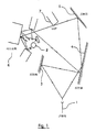
図1及び図2を参照して、固定式送信機と移動式無線通信端末との間のマルチパスデータの送信の実施例及びそのような送信に適合した基準構造を割り当てる仕組みが示される。 With reference to FIGS. 1 and 2, an embodiment of transmission of multipath data between a fixed transmitter and a mobile radio communication terminal and a mechanism for assigning a reference structure suitable for such transmission are shown.
送信機1は、ディジタルデータを移動式無線通信端末2に送信する。例えば、そのような端末2は、ユーザに属する移動する車両内に設置されている。ステーション1によって送信された信号は、端末2に到達する前に様々な経路をたどる。特に、その信号は、反射器3,4及び5で数回反射される。その信号は、さらに、障害物7により回折され、また端末2に近い領域6内で局所的に分散される。このため、移動式端末2は、固定式ステーション1によって送信されるが、移動式端末2に到達するためにたどった経路の関数として何回も相殺されたいくつかの同じ信号を受信する。
The
送信機1と端末2との間に設定された送信チャネルは、最大の「遅延スプレッド」によって、換言すると、送信機1と端末2との間に図1で示した最も長い経路に関連した伝搬時間の最大のスプレッドによって特に特徴付けられる。
The transmission channel set up between the
送信チャネルは、端末2の速度に関連した最大のドップラ周波数によっても特徴付けられる。 The transmission channel is also characterized by the maximum Doppler frequency associated with the speed of the terminal 2.
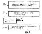
図2に示すように、送信チャネルのこれらの特性(最大のドップラスプレッド及び最大の遅延スプレッド)は、無線通信装置2と遠隔ステーション1との間の参照ステップ20の間に、メッセージの形式が交換される。
As shown in FIG. 2, these characteristics of the transmission channel (maximum Doppler spread and maximum delay spread) are exchanged during the
交換された情報に基づいて、検討する無線通信ネットワーク内のステーション1は、装置2とステーション1との間の通信に、送信チャネルの特性に適合した基準パターンを有する周波数のチャネルを割り当てることを決定する。割り当てることができる各種の周波数のチャネルは機能的には同一であるが、基準記号の分布に関しては波形が異なっている。このため、送信チャネルの特性が向上するにつれて(言い換えると、送信環境がより良くなるにつれて)、通信システムは送信チャネルの伝達関数を評価するため及び同期を維持するためにチャネル容量をそれほど消費しなくなり、また送信容量及び/又はエラー保護能力をそれ相応に向上させることができる。
Based on the exchanged information, the
端末2がその環境の中で移動することにより、又は例えば、その移動速度が変化することによって、送信チャネルの特性は時間と共に変化することがある。(22)。 The characteristics of the transmission channel may change over time as the terminal 2 moves in its environment or, for example, as its moving speed changes. (22).
次に、参照ステップ23の間に、ステーション1は装置2と協同して関係する基準構造を変化させることができる。この種の基準構造はブロックの持続時間の間は変化しないが、1つのブロックから他のブロックに変化することができる。例えば、「内部引継」形の手順を用いて、この種の変更をリアルタイムで行うことができる。携帯電話を用いる無線通信セルラーシステムでは、「引継」という用語は、通信を妨害せずに通信に使用される送信手段を切り換えることを意味することを思い出してほしい。
Next, during the
ブロックによる送信の場合、送信チャネルをサブブロックの持続時間の間は準定常であると考えることができるように、ブロックをいくつかのサブブロックに細分化することを考えることも可能である。このため、ブロックの持続時間が、例えばWCMDAチャネルから得られた初期の同期に対して長すぎて、ブロックの持続時間の全体にわたって有効であると考えられない場合は、ブロックを基準パターンとは一般に異なるサブブロックに細分化することができる。次に、連続的に送信された各サブブロックに関連した基準パターンが、優れたチャネル評価を行うように決定される。より一般的には、特にチャネルの定常性を考慮しながら、ブロックの長さを何らかの適当な方法を用いて適合させる。 For transmission by block, it is also possible to consider subdividing the block into several sub-blocks so that the transmission channel can be considered quasi-stationary for the duration of the sub-block. For this reason, a block is generally referred to as a reference pattern if the duration of the block is too long for the initial synchronization, eg obtained from the WCMDA channel, and is not considered valid throughout the duration of the block. Can be subdivided into different sub-blocks. Next, a reference pattern associated with each successively transmitted sub-block is determined to perform good channel estimation. More generally, the length of the block is adapted using any suitable method, especially taking into account channel continuity.
特に有効なサブキャリアと基準サブキャリアとの間のエネルギーの非対称性を用いることによる、ステーション1と装置2との間の同期トラッキング機構(synchronisation tracking mechanism)の使用を検討することも可能である。
It is also possible to consider the use of a synchronization tracking mechanism between
図3に示すように、チャネル評価ステップ30が、送信特性を決定するために実行される。送信チャネルが準定常であるとみなすことができる間に最大の持続時間に何らかの変化がある場合(31)、WCDMA形のチャネルを用いて得られた初期の同期がブロックの持続時間全体に有効であるように、送信されたデータブロックの持続時間を変更することを考えることは可能である。
As shown in FIG. 3, a
送信チャネルの特性の変化に基づいて(33)(例えば、通信環境の変化の関数として)、次のステップ(34)で、各データブロックに適合した基準パターンの構造が決定される。 Based on changes in the characteristics of the transmission channel (33) (eg, as a function of changes in the communication environment), the next step (34) determines the structure of the reference pattern that fits each data block.
ここで、OFDM/OQAM/IOTA形の変調を用いる送信システムの枠組みの中で、図3から図5を参照して、本発明による送信チャネルの伝達関数を評価するために一連のパイロット記号を抽出する方法の実施形態を説明する。明らかに、本発明はチャネル評価が必要な任意の他のデータ送信システム、また特にモノキャリア(mono-carrier)形の変調を用いる送信システムに等しく適用できる。 Now, in the framework of a transmission system using OFDM / OQAM / IOTA type modulation, referring to FIGS. 3 to 5, a series of pilot symbols is extracted to evaluate the transfer function of the transmission channel according to the present invention. An embodiment of the method to do will be described. Obviously, the present invention is equally applicable to any other data transmission system where channel estimation is required, and in particular to a transmission system using mono-carrier type modulation.
特に、本発明は、本願と同じ出願人によって提出された、「Cellular radio telephony signal with a supplementary channel assigned to the down direction, and the corresponding method, system, mobile and base station」という題名のフランス特許第2,777,407号の中で説明された送信システムの一部として使用することができる。 In particular, the present invention relates to a second French patent entitled “Cellular radio telephony signal with a supplementary channel assigned to the down direction, and the corresponding method, system, mobile and base station” filed by the same applicant as the present application. 777,407, as part of the transmission system described in US Pat.
マルチキャリアシステムは、フェーディング及び複数の経路によって影響された送信に対して、特に、それらがエラー補正コード及びインターレースに関連する場合は特に魅力的であることを思い出してほしい。 Recall that multi-carrier systems are particularly attractive for transmissions affected by fading and multiple paths, especially when they relate to error correction codes and interlaces.
OFDM変調の1つの主な特徴は、キャリアネットワークの密度である。この密度は、IOTAのようなOFDM/OQAM(「Orthogonal Frequency Division Multiplex/Offset Quadrature Amplitude Modulation」)形の変調に対しては2に等しい。キャリアネットワークの密度が、(τ0ν0)-1で定義されることも思い出してほしい。ここで、τ0は記号時間を示し、ν0はサブキャリア間の間隔を示す。 One main feature of OFDM modulation is the density of the carrier network. This density is equal to 2 for OFDM / OQAM (“Orthogonal Frequency Division Multiplex / Offset Quadrature Amplitude Modulation”) type modulation such as IOTA. Recall that the density of the carrier network is defined by (τ 0 ν 0 ) −1 . Here, τ 0 indicates a symbol time, and ν 0 indicates an interval between subcarriers.
ドップラ周波数及び遅延スプレッドのパラメータによって特徴付けられたチャネルについては、送信された信号に対する送信チャネルの影響は対称的である。ドップラスプレッド及び遅延スプレッドによる劣化は両方とも、直接空間における畳込み及びフィルタリング、及びこれによる逆格子空間における増加又は減衰に相当する。さらに、IOTAのプロトタイプ関数は、標準化された変数τ0=1/√2及びν0=1/√2に対して完全な時間−周波数の対称性を有する。 For channels characterized by Doppler frequency and delay spread parameters, the effect of the transmission channel on the transmitted signal is symmetric. Both degradation due to Doppler spread and delay spread correspond to convolution and filtering in direct space, and thus increase or decay in reciprocal space. Furthermore, the IOTA prototype function has perfect time-frequency symmetry with respect to the standardized variables τ 0 = 1 / √2 and ν 0 = 1 / √2.
送信チャネル及びプロトタイプの関数が対称的であるため、時間及び周波数内で識別された基本的な信号は、チャネルと同じ時間−周波数の尺度を用いて使用することができる。このため、最大のドップラ及び最大の遅延スプレッドは、記号の持続時間を最適化することによって標準単位で同一にされる。 Because the transmission channel and prototype functions are symmetric, the fundamental signal identified in time and frequency can be used with the same time-frequency measure as the channel. Thus, the maximum Doppler and maximum delay spread are made identical in standard units by optimizing the symbol duration.
この条件により、送信された信号ができるだけ悪影響を受けないように、時間及び周波数の次元のいずれも送信の間に所定の優先順位ではないことが確実にされる。 This condition ensures that neither time nor frequency dimensions are of a predetermined priority during transmission so that the transmitted signal is not adversely affected as much as possible.
[I.1 パイロットネットワークの構造]
Ntを2つのパイロット間の間隔とし、Nfを周波数の間隔とする。(τ0,ν0,Nt,Nf)のパラメータの組合せは、物理的なチャネルを定義する。このため、伝搬チャネルは、固有の物理的チャネルに相当する。
[I. 1 Pilot network structure]
Let N t be the interval between two pilots and N f be the frequency interval. The combination of parameters (τ 0 , ν 0 , N t , N f ) defines a physical channel. For this reason, the propagation channel corresponds to a specific physical channel.
伝搬チャネルのパラメータの関数としてパイロットを組み入れることは、動的に管理される。この文書の残りの中に記載された1つの特定の実施形態によれば、送信されたブロックは、隣り合う送信されたブロック間の干渉を減らすため、また増幅器の立上り時間を考慮するために、保護間隔により制限される。 Incorporating pilots as a function of propagation channel parameters is managed dynamically. According to one particular embodiment described in the rest of this document, transmitted blocks are used to reduce interference between adjacent transmitted blocks and to account for amplifier rise times. Limited by protection interval.
基準記号は、チャネル評価ウィンドウ上に均一に配置されて、大きなチャネル変動に対する最良の評価により特徴付けられ、またそれを提供する。これらの記号は、有効なスループットを最大にしながら、記号から情報を最大限に引き出すために互いにできるだけ分離される。 The reference symbol is uniformly placed on the channel evaluation window and is characterized and provides the best estimate for large channel variations. These symbols are separated as much as possible from each other to maximize information from the symbols while maximizing effective throughput.
[I.2 基準キャリアネットワーク及び記号時間の適合]
<I.2.1 記号時間の適合>
3GPPにより定義されたUMTS規格に基づいて、本発明の特定の実施形態を検討する。WCDMA形のチャネルから得られた同期を使用し、また伝搬チャネルの形式についての情報が得られていると仮定する。次に、OFDM/IOTA変調を用いるチャネルに切り換える。チャネルを作るフィルタの支持体の比率がτ0とν0との比率に比例する(2)ように記号時間及びサブキャリア間の間隔を決定するために、ネットワークの密度が2に固定される(1)ことを考えて、各伝搬チャネルの種類に対して最大ドップラ及び最大遅延についての情報を使用する。

<I. 2.1 Adaptation of symbol time>
Consider specific embodiments of the present invention based on the UMTS standard defined by 3GPP. Assume that the synchronization obtained from a WCDMA type channel is used and that information about the type of propagation channel is obtained. Next, it switches to the channel using OFDM / IOTA modulation. The network density is fixed at 2 in order to determine the symbol time and the spacing between subcarriers so that the ratio of the filter supports that make up the channel is proportional to the ratio of τ 0 to ν 0 (2) ( 1) Considering that, information about maximum Doppler and maximum delay is used for each type of propagation channel.
次に、記号時間はシステムのフレーム構造(3)を考慮する必要がある。
Tslot/τ0=p,pint eger (3)
ここで、Tslotはスロットの持続時間である。
Next, the symbol time needs to consider the system frame structure (3).
T slot / τ 0 = p, pin egg (3)
Here, T slot is the duration of the slot.
ETSIによって定義されたUMTS形のチャネルの分析から得られたτ0及びν0の異なった値(例えば、付属書B.1の資料TR101,112V3.2.0を参照されたい)は、下記の表で与えられる。 The different values of τ 0 and ν 0 obtained from analysis of UMTS type channels defined by ETSI (see, for example, Annex TR.1 material TR101, 112V3.2.0) Given in the table.
記号時間のこの種の適合は、従来のOFDM変調に基づいた送信システムに対するこの形式の中では考えられないことを思い出してほしい。 Recall that this type of symbol time adaptation is not considered within this form for a transmission system based on conventional OFDM modulation.
<I.2.2 パイロット分布の決定>
Ntの決定
Ntを時間次元によるパイロットのサンプリングステップとする。
<I. 2.2 Determination of pilot distribution>
Determination of N t Let N t be the pilot sampling step in the time dimension.
(シャノンの理論と呼ばれる)サンプリング理論によれば、時間次元Ntτ0によるパイロットのサンプリング周期は、下記の式を満足する必要がある。
Ntτ0≦1/BD
ここで、BDはドップラ周波数の帯域[−FD,+FD]であり、FDは最大のドップラ周波数であり、BD=2*FDである。
According to the sampling theory (referred to as Shannon's theory), the pilot sampling period with the time dimension N t τ 0 must satisfy the following equation.
N t τ 0 ≦ 1 / B D
Here, B D is the band [−F D , + F D ] of the Doppler frequency, F D is the maximum Doppler frequency, and B D = 2 * F D.
Nfの決定
Nfを周波数次元によるパイロットのサンプリングステップとする。
Determination of N f Let N f be the pilot sampling step in the frequency dimension.
周波数次元Nfν0によるパイロットのサンプリング周期は、下記の式を満足する必要がある。
Nfν0≦1/Tmax (4)
ここで、Tmaxは最大の遅延スプレッドである。
The sampling period of the pilot with the frequency dimension N f ν 0 needs to satisfy the following equation.
N f ν 0 ≦ 1 / T max (4)
Here, T max is the maximum delay spread.
このため、上記のように定義された2つの式が満足されるように、パラメータNt及びNf並びにこれらのパラメータから結果として生じたキャリアネットワーク内のパイロットの分布が決定される。 Thus, the parameters N t and N f and the resulting distribution of pilots in the carrier network are determined from these parameters so that the two equations defined above are satisfied.
<I.2.3 評価ウィンドウの大きさの決定>
この特定の実施形態の中で示された送信システムは、いくつかのユーザ間で高速の送信リソースを共有することが考えられる。特に、パケット送信を使用する送信システムを考える。その結果、この種のシステムは、所定の周波数帯域に対して任意の大きさのパケットの送信を行うことができる。特に、送信されたブロックの大きさにおけるこの多様性により、データブロックの最小の大きさを固定する小さい評価ウィンドウを使用することができる。
<I. 2.3 Determination of Evaluation Window Size>
It is contemplated that the transmission system shown in this particular embodiment shares high speed transmission resources among several users. In particular, consider a transmission system that uses packet transmission. As a result, this type of system can transmit a packet of an arbitrary size for a predetermined frequency band. In particular, due to this diversity in transmitted block size, a small evaluation window can be used that fixes the minimum size of the data block.
図4は、評価ウィンドウ内のパイロットの分布を示す。基準記号41は、時間空間Nf及び周波数空間Ntに関係するキャリアネットワークの中に均一に配置されている。
FIG. 4 shows the distribution of pilots within the evaluation window. The
図5に示すように、評価ウィンドウ内にパイロットが平行四辺形に分布することも考えられる。 As shown in FIG. 5, it is conceivable that the pilots are distributed in a parallelogram within the evaluation window.
基準キャリアと有効キャリアとの間のエネルギーの非対称性は、送信された信号の平均パワープロフィールに大きな変動をもたらすことがある。このため、パイロットネットワークの形状は、送信の間に使用される電力増幅器の非直線性による劣化を抑えるために、信号の包絡線の変動を減少させる制約によって決まる。 The energy asymmetry between the reference carrier and the effective carrier can cause large variations in the average power profile of the transmitted signal. For this reason, the shape of the pilot network is determined by constraints that reduce fluctuations in the envelope of the signal in order to suppress degradation due to nonlinearity of the power amplifier used during transmission.
このように、図5は、時間−周波数空間内の情報記号ネットワーク50の実施例を示す。ここで、基準記号51は、平行四辺形のパターン52を形成するように均一に配置される。
Thus, FIG. 5 shows an embodiment of an
[I.3 送信の原理]
図6は、本発明による信号送信機の簡略化したブロック図を示す。
[I. 3 Principle of transmission]
FIG. 6 shows a simplified block diagram of a signal transmitter according to the present invention.
高速のバイナリソース(binary source)60を検討する。バイナリソースとは、任意の種類(音声、画像、データ)のサンプリングされたディジタル又はアナログ信号の1つ又はいくつかのソースに対応する一連のデータのことを指す。これらのバイナリデータは、フェーディングを有するチャネルに適合されたバイナリ間のチャネルコーディング61を受ける。例えば、恐らくリード−ソロモンコード(Reed-Solomon code)(内部コードとして動作する畳込みコード)と結び付いたトレリスコード(trellis code)、又はターボコード(Turbo Code)を使用できる。
Consider a fast
最後に、これらのデータは時間−周波数空間の中に配置され(62)て、必要な多様性を提供し、また送信された記号に影響を与えるレイリーのフェーディング(Rayleigh fading)を逆相関する。 Finally, these data are placed in time-frequency space (62) to provide the required diversity and to inversely correlate Rayleigh fading that affects the transmitted symbols. .
より一般的に言うと、時間及び周波数の組合せ並びに係数付きのバイナリのコーディング(マッピング)と一緒に、第1のバイナリ間のコーディングが行われる。 More generally, the first inter-binary coding is performed along with the combination of time and frequency and binary coding (mapping) with coefficients.
このコーディング動作の後、送信される実際の記号am,nが利用可能になり、その後それらの記号はOFDM/OQAM/IOTA変調器64を用いて変調される。
After this coding operation, the actual symbols a m, n to be transmitted are available, after which those symbols are modulated using the OFDM / OQAM /
フレーム形成ブロック63は、キャリアネットワークの中にパイロットを挿入する。パイロットの挿入パターン(時間及び周波数内のパイロットの数、パイロット間の間隔)は、チャネルの特性及び送信されたブロックの大きさに依存する。それらは、受信機が周知のパラメータである。
The framing
変調器64からの出力で生成された複合信号は、次に、アナログ形式に変換され(65)、次に直角位相の2つのチャネルを有する変調器によって最終的な周波数に(I及びQ)置き換えられ(66)、最終的に、送信される前(68)に増幅される(67)。
The composite signal generated at the output from the
[I.4 受信機の原理]
本発明による信号受信機は、特に、同期に対して使用される受信されたサンプルと受信機には周知の順序からのサンプルとの間の補正しきい値のオーバシュートを検出する手段と、送信チャネルの伝達関数を評価する手段とを含む従来の受信機の構造と同じ構造を有する。
[I. 4 Principle of receiver]
The signal receiver according to the invention comprises, in particular, means for detecting a correction threshold overshoot between received samples used for synchronization and samples from a sequence well known to the receiver, And having the same structure as that of a conventional receiver including means for evaluating the transfer function of the channel.
本発明によれば、この種の受信機は、可変構造の基準パターンに適合する手段も備える。特に、そのような受信機は、下記のモードの1つに基づいて動作することができる。
・第1の動作モードによる。このモードでは、受信機は信号チャネルを通して通信の間に使用される基準パターンの構造に関する情報を受信する手段を使用する。
・第2の動作モードによる。このモードでは、受信機は、前に測定された送信特性の関数として、通信の間に使用された必要な基準パターンの構造を決定する。
According to the invention, this type of receiver also comprises means for adapting to the variable structure reference pattern. In particular, such a receiver can operate based on one of the following modes:
-According to the first operation mode. In this mode, the receiver uses a means for receiving information regarding the structure of the reference pattern used during communication over the signal channel.
-According to the second operation mode. In this mode, the receiver determines the structure of the required reference pattern used during communication as a function of previously measured transmission characteristics.
別の方式による第1の動作モードでは、信号及び制御情報(及び特に、時間−周波数ブロックの識別情報)が、WCDMA形のチャネルに送られる。第2の動作モードでは、この情報は、ブロック送信時間の間にIOTAチャネルに対して変更される。全ての場合、WCDMA形のチャネルから得られた同期が使用され、また最大の周波数及び時間のスプレッドが周知であると仮定されている。 In a first mode of operation according to another scheme, signal and control information (and in particular time-frequency block identification information) is sent over a WCDMA type channel. In the second mode of operation, this information is changed for the IOTA channel during the block transmission time. In all cases, synchronization derived from WCDMA type channels is used and it is assumed that the maximum frequency and time spread is well known.
Claims (42)
前記基準パターンは、少なくとも2つのパイロット記号(N t )間の時間の間隔と、2つのパイロット記号(N f )間の周波数の間隔とによって定義される時間−周波数空間内に構造を有し、
前記2つのパイロット記号(N t )間の時間の間隔の値及び/又は前記2つのパイロット記号(N f )間の周波数の間隔の値を含む前記基準パターンの構造の少なくとも1つの特徴は、前記信号の送信の間に可変であり、
前記信号を受信するステップと、
前記信号から現在の基準パターンを抽出するステップと、
前記現在の基準パターンを分析して、前記送信チャネルの最大のドップラ周波数及び最大の遅延スプレッドからなるグループに属する前記送信チャネルの少なくとも1つの特性を提供するステップと、
前記2つのパイロット記号(N t )間の時間の間隔の値及び/又は前記2つのパイロット記号(N f )間の周波数の間隔の値を含む次の基準パターンの特徴を、送信チャネルの特性の関数として測定するステップと、
を含むことを特徴とする方法。A series of at least one wireless communication device may communicate through a remote station and transmitting a channel to regularly insert a reference pattern on a signal transmitted to the wireless communication device, evaluating the transfer function of the transmission channel A method for extracting pilot symbols of
The reference pattern has a structure in a time-frequency space defined by a time interval between at least two pilot symbols (N t ) and a frequency interval between two pilot symbols (N f );
At least one feature of the structure of the reference pattern including a value of a time interval between the two pilot symbols (N t ) and / or a value of a frequency interval between the two pilot symbols (N f ) is Variable during transmission of the signal,
Receiving the signal;
Extracting a current reference pattern from the signal;
Analyzing the current reference pattern to provide at least one characteristic of the transmission channel belonging to a group consisting of a maximum Doppler frequency and a maximum delay spread of the transmission channel;
The characteristics of the next reference pattern, including the value of the time interval between the two pilot symbols (N t ) and / or the value of the frequency interval between the two pilot symbols (N f ), Measuring as a function;
A method comprising the steps of:
前記少なくとも1つの割り当てられたチャネルの各々は、前記送信チャネルの特性の関数として、機能的には同一であるが前記基準パターンの構造に関しては別個の波形に基づくものである請求項1に記載の方法。 Allocating at least one channel for communication;
2. Each of the at least one assigned channel is based on a separate waveform with respect to the structure of the reference pattern that is functionally identical as a function of the characteristics of the transmission channel . Method.
前記基準パターンは、少なくとも2つのパイロット記号(NThe reference pattern includes at least two pilot symbols (N tt )間の時間の間隔と、2つのパイロット記号(N) And the time between two pilot symbols (N ff )間の周波数の間隔とによって定義される時間−周波数空間内に構造を有し、Having a structure in the time-frequency space defined by the frequency spacing between
前記信号を受信するステップと、Receiving the signal;
前記信号から現在の基準パターンを抽出するステップと、Extracting a current reference pattern from the signal;
前記現在の基準パターンを分析して、前記送信チャネルの最大のドップラ周波数及び最大の遅延スプレッドからなるグループに属する前記送信チャネルの少なくとも1つの特性を測定するステップと、Analyzing the current reference pattern to measure at least one characteristic of the transmission channel belonging to a group consisting of a maximum Doppler frequency and a maximum delay spread of the transmission channel;
前記2つのパイロット記号(NThe two pilot symbols (N tt )間の時間の間隔の値及び/又は前記2つのパイロット記号(N) And / or the two pilot symbols (N ff )間の周波数の間隔の値を含む、基準パターンの少なくとも1つの次の特徴を有する前記基準パターンの次の構造を、送信チャネルの特性の関数として測定するステップと、Measuring a next structure of the reference pattern having at least one next characteristic of the reference pattern as a function of the characteristics of the transmission channel, including a frequency spacing value between
前記次の構造を有する次の基準パターンを抽出するステップと、Extracting a next reference pattern having the next structure;
を含むことを特徴とする方法。A method comprising the steps of:
前記少なくとも1つの割り当てられたチャネルの各々は、前記送信チャネルの特性の関数として、機能的には同一であるが前記基準パターンの構造に関しては別個の波形に基づくものである請求項21に記載の方法。22. Each of the at least one assigned channel is based on a separate waveform with respect to the structure of the reference pattern that is functionally identical as a function of the characteristics of the transmission channel. Method.
前記基準パターンは、少なくとも2つのパイロット記号(NThe reference pattern includes at least two pilot symbols (N tt )間の時間の間隔と、2つのパイロット記号(N) And the time between two pilot symbols (N ff )間の周波数の間隔とによって定義される時間−周波数空間内に構造を有し、Having a structure in the time-frequency space defined by the frequency spacing between
前記信号を受信する手段と、Means for receiving the signal;
前記信号から現在の基準パターンを抽出する手段と、Means for extracting a current reference pattern from the signal;
前記現在の基準パターンを分析して、前記送信チャネルの最大のドップラ周波数及び最大の遅延スプレッドからなるグループに属する前記送信チャネルの少なくとも1つの特性を測定する手段と、Means for analyzing the current reference pattern and measuring at least one characteristic of the transmission channel belonging to a group consisting of a maximum Doppler frequency and a maximum delay spread of the transmission channel;
前記2つのパイロット記号(NThe two pilot symbols (N tt )間の時間の間隔の値及び/又は前記2つのパイロット記号(N) And / or the two pilot symbols (N ff )間の周波数の間隔の値を含む、基準パターンの少なくとも1つの次の特徴を有する前記基準パターンの次の構造を、送信チャネルの特性の関数として測定する手段と、Means for measuring the next structure of the reference pattern having at least one of the following features of the reference pattern as a function of the characteristics of the transmission channel, including a frequency spacing value between:
前記次の構造を有する次の基準パターンを抽出する手段と、Means for extracting a next reference pattern having the next structure;
を備えることを特徴とする装置。A device comprising:
前記基準パターンは、少なくとも2つのパイロット記号(NThe reference pattern includes at least two pilot symbols (N tt )間の時間の間隔と、2つのパイロット記号(N) And the time between two pilot symbols (N ff )間の周波数の間隔とによって定義される時間−周波数空間内に構造を有し、Having a structure in the time-frequency space defined by the frequency spacing between
前記信号に現在の基準パターンを挿入する手段と、Means for inserting a current reference pattern into the signal;
前記送信チャネルの最大のドップラ周波数及び最大の遅延スプレッドからなるグループに属する前記送信チャネルの少なくとも1つの特性を得る手段と。Means for obtaining at least one characteristic of the transmission channel belonging to a group consisting of a maximum Doppler frequency and a maximum delay spread of the transmission channel;
前記2つのパイロット記号(NThe two pilot symbols (N tt )間の時間の間隔の値及び/又は前記2つのパイロット記号(N) And / or the two pilot symbols (N ff )間の周波数の間隔の値を含む、基準パターンの少なくとも1つの次の特徴を有する前記基準パターンの次の構造を、送信チャネルの特性の関数として測定する手段と、Means for measuring the next structure of the reference pattern having at least one of the following features of the reference pattern as a function of the characteristics of the transmission channel, including a frequency spacing value between:
前記次の構造を有する次の基準パターンを前記信号に挿入する手段と、Means for inserting a next reference pattern having the next structure into the signal;
を備えることを特徴とする遠隔ステーション。A remote station comprising:
Applications Claiming Priority (2)
| Application Number | Priority Date | Filing Date | Title |
|---|---|---|---|
| FR0101751A FR2820574B1 (en) | 2001-02-08 | 2001-02-08 | METHOD FOR EXTRACTING A REFERENCE SYMBOL PATTERN FOR ESTIMATING THE TRANSFER FUNCTION OF A TRANSMIT CHANNEL, SIGNAL, DEVICE AND CORRESPONDING METHODS |
| PCT/FR2002/000486 WO2002065685A1 (en) | 2001-02-08 | 2002-02-07 | Method for extracting a variable reference pattern |
Publications (3)
| Publication Number | Publication Date |
|---|---|
| JP2004530319A JP2004530319A (en) | 2004-09-30 |
| JP2004530319A5 JP2004530319A5 (en) | 2006-01-05 |
| JP4150591B2 true JP4150591B2 (en) | 2008-09-17 |
Family
ID=8859809
Family Applications (1)
| Application Number | Title | Priority Date | Filing Date |
|---|---|---|---|
| JP2002564876A Expired - Fee Related JP4150591B2 (en) | 2001-02-08 | 2002-02-07 | How to extract a variable reference pattern |
Country Status (8)
| Country | Link |
|---|---|
| US (1) | US7313174B2 (en) |
| EP (1) | EP1358728A1 (en) |
| JP (1) | JP4150591B2 (en) |
| KR (1) | KR100914021B1 (en) |
| CN (1) | CN1496622B (en) |
| BR (1) | BR0207123A (en) |
| FR (1) | FR2820574B1 (en) |
| WO (1) | WO2002065685A1 (en) |
Families Citing this family (76)
| Publication number | Priority date | Publication date | Assignee | Title |
|---|---|---|---|---|
| US9130810B2 (en) | 2000-09-13 | 2015-09-08 | Qualcomm Incorporated | OFDM communications methods and apparatus |
| US7295509B2 (en) | 2000-09-13 | 2007-11-13 | Qualcomm, Incorporated | Signaling method in an OFDM multiple access system |
| US7035595B1 (en) * | 2002-01-10 | 2006-04-25 | Berkana Wireless, Inc. | Configurable wireless interface |
| US20040017860A1 (en) * | 2002-07-29 | 2004-01-29 | Jung-Tao Liu | Multiple antenna system for varying transmission streams |
| KR100507519B1 (en) | 2002-12-13 | 2005-08-17 | 한국전자통신연구원 | Method and Apparatus for Signal Constitution for Downlink of OFDMA Based Cellular Systems |
| CN1306745C (en) * | 2003-05-30 | 2007-03-21 | 电子科技大学 | Guiding plan based on time frequency synchronous training sequence |
| KR101160135B1 (en) * | 2003-08-12 | 2012-06-26 | 파나소닉 주식회사 | Radio communication apparatus and pilot symbol transmission method |
| US7092353B2 (en) * | 2003-10-17 | 2006-08-15 | Qualcomm Incorporated | Carrier search methods and apparatus |
| US7339999B2 (en) | 2004-01-21 | 2008-03-04 | Qualcomm Incorporated | Pilot transmission and channel estimation for an OFDM system with excess delay spread |
| US8553822B2 (en) | 2004-01-28 | 2013-10-08 | Qualcomm Incorporated | Time filtering for excess delay mitigation in OFDM systems |
| EP1589687A1 (en) * | 2004-04-23 | 2005-10-26 | France Telecom | Method for sending a signal in a multi-antenna system, corresponding signal and method for channel estimation |
| US7457231B2 (en) * | 2004-05-04 | 2008-11-25 | Qualcomm Incorporated | Staggered pilot transmission for channel estimation and time tracking |
| CN100359959C (en) * | 2004-06-01 | 2008-01-02 | 华为技术有限公司 | Method for implementing channel estimation in OFDMA system |
| GB2415872B (en) * | 2004-06-30 | 2007-09-05 | Samsung Electronics Co Ltd | Multicarrier transmission systems |
| US9137822B2 (en) | 2004-07-21 | 2015-09-15 | Qualcomm Incorporated | Efficient signaling over access channel |
| US9148256B2 (en) | 2004-07-21 | 2015-09-29 | Qualcomm Incorporated | Performance based rank prediction for MIMO design |
| JP4805169B2 (en) * | 2005-01-06 | 2011-11-02 | 富士通株式会社 | Wireless communication system |
| ATE548828T1 (en) * | 2005-03-08 | 2012-03-15 | Ericsson Telefon Ab L M | METHOD AND ARRANGEMENT FOR ADVANCED ROUTING METRICS IN MULTI-JUNK NETWORKS |
| US9246560B2 (en) | 2005-03-10 | 2016-01-26 | Qualcomm Incorporated | Systems and methods for beamforming and rate control in a multi-input multi-output communication systems |
| US9154211B2 (en) | 2005-03-11 | 2015-10-06 | Qualcomm Incorporated | Systems and methods for beamforming feedback in multi antenna communication systems |
| US8446892B2 (en) | 2005-03-16 | 2013-05-21 | Qualcomm Incorporated | Channel structures for a quasi-orthogonal multiple-access communication system |
| US9520972B2 (en) | 2005-03-17 | 2016-12-13 | Qualcomm Incorporated | Pilot signal transmission for an orthogonal frequency division wireless communication system |
| US9143305B2 (en) | 2005-03-17 | 2015-09-22 | Qualcomm Incorporated | Pilot signal transmission for an orthogonal frequency division wireless communication system |
| US9461859B2 (en) * | 2005-03-17 | 2016-10-04 | Qualcomm Incorporated | Pilot signal transmission for an orthogonal frequency division wireless communication system |
| US9184870B2 (en) | 2005-04-01 | 2015-11-10 | Qualcomm Incorporated | Systems and methods for control channel signaling |
| JPWO2006107037A1 (en) * | 2005-04-04 | 2008-09-25 | 日本電気株式会社 | OFDM communication system, feedback information generation method thereof, and communication apparatus |
| US9408220B2 (en) | 2005-04-19 | 2016-08-02 | Qualcomm Incorporated | Channel quality reporting for adaptive sectorization |
| US9036538B2 (en) | 2005-04-19 | 2015-05-19 | Qualcomm Incorporated | Frequency hopping design for single carrier FDMA systems |
| US20060240784A1 (en) * | 2005-04-22 | 2006-10-26 | Qualcomm Incorporated | Antenna array calibration for wireless communication systems |
| US8611284B2 (en) | 2005-05-31 | 2013-12-17 | Qualcomm Incorporated | Use of supplemental assignments to decrement resources |
| US8879511B2 (en) | 2005-10-27 | 2014-11-04 | Qualcomm Incorporated | Assignment acknowledgement for a wireless communication system |
| US8565194B2 (en) | 2005-10-27 | 2013-10-22 | Qualcomm Incorporated | Puncturing signaling channel for a wireless communication system |
| US8462859B2 (en) | 2005-06-01 | 2013-06-11 | Qualcomm Incorporated | Sphere decoding apparatus |
| US8599945B2 (en) | 2005-06-16 | 2013-12-03 | Qualcomm Incorporated | Robust rank prediction for a MIMO system |
| US8498669B2 (en) * | 2005-06-16 | 2013-07-30 | Qualcomm Incorporated | Antenna array calibration for wireless communication systems |
| US9179319B2 (en) | 2005-06-16 | 2015-11-03 | Qualcomm Incorporated | Adaptive sectorization in cellular systems |
| KR20110074620A (en) | 2005-07-29 | 2011-06-30 | 파나소닉 주식회사 | Communication apparatus, communication method, and integrated circuit |
| US8885628B2 (en) | 2005-08-08 | 2014-11-11 | Qualcomm Incorporated | Code division multiplexing in a single-carrier frequency division multiple access system |
| US20070041457A1 (en) | 2005-08-22 | 2007-02-22 | Tamer Kadous | Method and apparatus for providing antenna diversity in a wireless communication system |
| US9209956B2 (en) | 2005-08-22 | 2015-12-08 | Qualcomm Incorporated | Segment sensitive scheduling |
| US8644292B2 (en) | 2005-08-24 | 2014-02-04 | Qualcomm Incorporated | Varied transmission time intervals for wireless communication system |
| US9136974B2 (en) | 2005-08-30 | 2015-09-15 | Qualcomm Incorporated | Precoding and SDMA support |
| WO2007037414A1 (en) * | 2005-09-30 | 2007-04-05 | Matsushita Electric Industrial Co., Ltd. | Wireless communication mobile station apparatus and rach data transmitting method |
| US10979981B2 (en) * | 2005-10-07 | 2021-04-13 | Nokia Technologies Oy | Apparatus, method and computer program product providing common pilot channel for soft frequency reuse |
| US8582509B2 (en) | 2005-10-27 | 2013-11-12 | Qualcomm Incorporated | Scalable frequency band operation in wireless communication systems |
| US9210651B2 (en) | 2005-10-27 | 2015-12-08 | Qualcomm Incorporated | Method and apparatus for bootstraping information in a communication system |
| US8693405B2 (en) | 2005-10-27 | 2014-04-08 | Qualcomm Incorporated | SDMA resource management |
| US9172453B2 (en) | 2005-10-27 | 2015-10-27 | Qualcomm Incorporated | Method and apparatus for pre-coding frequency division duplexing system |
| US9225416B2 (en) | 2005-10-27 | 2015-12-29 | Qualcomm Incorporated | Varied signaling channels for a reverse link in a wireless communication system |
| US8477684B2 (en) | 2005-10-27 | 2013-07-02 | Qualcomm Incorporated | Acknowledgement of control messages in a wireless communication system |
| US8045512B2 (en) | 2005-10-27 | 2011-10-25 | Qualcomm Incorporated | Scalable frequency band operation in wireless communication systems |
| US9088384B2 (en) | 2005-10-27 | 2015-07-21 | Qualcomm Incorporated | Pilot symbol transmission in wireless communication systems |
| US9144060B2 (en) | 2005-10-27 | 2015-09-22 | Qualcomm Incorporated | Resource allocation for shared signaling channels |
| US9225488B2 (en) | 2005-10-27 | 2015-12-29 | Qualcomm Incorporated | Shared signaling channel |
| JP4657888B2 (en) * | 2005-10-31 | 2011-03-23 | シャープ株式会社 | Transmitter and transmission method |
| US9118111B2 (en) * | 2005-11-02 | 2015-08-25 | Qualcomm Incorporated | Antenna array calibration for wireless communication systems |
| US8280430B2 (en) * | 2005-11-02 | 2012-10-02 | Qualcomm Incorporated | Antenna array calibration for multi-input multi-output wireless communication systems |
| US8582548B2 (en) | 2005-11-18 | 2013-11-12 | Qualcomm Incorporated | Frequency division multiple access schemes for wireless communication |
| JP4841235B2 (en) * | 2005-11-30 | 2011-12-21 | 富士通株式会社 | Wireless base station, wireless communication method, and wireless communication system |
| JP4899555B2 (en) * | 2006-03-17 | 2012-03-21 | 富士通株式会社 | Wireless communication system, transmitting apparatus and receiving apparatus |
| US8259852B2 (en) * | 2006-07-19 | 2012-09-04 | Broadcom Corporation | Method and system for satellite communication |
| KR101312746B1 (en) * | 2006-04-28 | 2013-09-27 | 닛본 덴끼 가부시끼가이샤 | Pilot signal transmitting method, radio communication system, and apparatus and program used for the same |
| JP4748678B2 (en) * | 2006-05-18 | 2011-08-17 | Kddi株式会社 | Radio apparatus, program and communication method for adaptively changing pilot signal arrangement |
| US20080200196A1 (en) * | 2007-02-19 | 2008-08-21 | Tarik Muharemovic | Transmission of prioritized information in the proximity of reference signals |
| FR2916116A1 (en) * | 2007-05-11 | 2008-11-14 | France Telecom | METHODS FOR TRANSMITTING AND RECEIVING A MULTIPLE CARRIER SIGNAL AND SPECTRUM SHIFTING, SIGNAL, COMPUTER PROGRAM PRODUCTS, AND CORRESPONDING TRANSMITTING AND RECEIVING DEVICES. |
| JP5382877B2 (en) * | 2007-08-31 | 2014-01-08 | パナソニック株式会社 | COMMUNICATION DEVICE, RECEPTION DEVICE, COMMUNICATION METHOD, RECEPTION METHOD, AND INTEGRATED CIRCUIT |
| KR101231512B1 (en) | 2008-05-09 | 2013-02-07 | 한국전자통신연구원 | Symbol timing synchronization method and apparatus robust to frequency offset in wireless communication systems |
| US8380531B2 (en) * | 2008-07-25 | 2013-02-19 | Invivodata, Inc. | Clinical trial endpoint development process |
| BR112012003454B1 (en) * | 2009-08-18 | 2021-08-24 | Koninklijke Philips N.V. | METHOD FOR OPERATING A PRIMARY STATION, INCLUDING MEANS FOR COMMUNICATION WITH A PLURALITY OF SECONDARY STATIONS, METHOD FOR OPERATING A SECONDARY STATION THAT INCLUDES MEANS FOR COMMUNICATION WITH AT LEAST ONE PRIMARY STATION, PRIMARY STATION THAT INCLUDES MEANS FOR COMMUNICATION WITH A PLURAL SECONDARY STATION AND SECONDARY STATION THAT COMPRISES MEANS FOR COMMUNICATION WITH AT LEAST ONE PRIMARY STATION |
| JP5138761B2 (en) * | 2010-11-22 | 2013-02-06 | シャープ株式会社 | Transmitter and transmission method |
| US9699791B2 (en) * | 2012-12-04 | 2017-07-04 | Lg Electronics Inc. | Method for changing pattern of reference signals according to movement speed of user equipment in wireless communication system, and an apparatus therefor |
| US10615899B1 (en) * | 2015-06-05 | 2020-04-07 | Aykut Bultan | Method and apparatus for implementing joint time frequency division multiplexing |
| EP3387748B1 (en) | 2015-12-09 | 2022-03-09 | Cohere Technologies, Inc. | Pilot packing using complex orthogonal functions |
| CN115694764A (en) | 2016-02-25 | 2023-02-03 | 凝聚技术公司 | Reference signal encapsulation for wireless communication |
| US11363572B2 (en) | 2016-08-01 | 2022-06-14 | Qualcomm Incorporated | Uplink channel dynamic waveform switching |
| US11382048B2 (en) | 2018-05-22 | 2022-07-05 | Qualcomm Incorporated | Multiplexing solutions in dual connectivity |
Family Cites Families (9)
| Publication number | Priority date | Publication date | Assignee | Title |
|---|---|---|---|---|
| FR2658016B1 (en) * | 1990-02-06 | 1994-01-21 | Etat Francais Cnet | METHOD FOR BROADCASTING DIGITAL DATA, ESPECIALLY FOR BROADBAND BROADCASTING TO MOBILES, WITH TIME-FREQUENCY INTERLACING AND CONSISTENT DEMODULATION, AND CORRESPONDING RECEIVER. |
| JPH1079701A (en) * | 1996-09-03 | 1998-03-24 | Fujitsu Ltd | Mobile communication terminal and its transmission power control system |
| US6654429B1 (en) * | 1998-12-31 | 2003-11-25 | At&T Corp. | Pilot-aided channel estimation for OFDM in wireless systems |
| EP1030489A1 (en) * | 1999-02-17 | 2000-08-23 | Interuniversitair Micro-Elektronica Centrum Vzw | Multicarrier transceiver |
| EP1061705B1 (en) * | 1999-06-16 | 2004-12-22 | Sony International (Europe) GmbH | Optimized synchronization preamble structure for OFDM system |
| EP1065855A1 (en) * | 1999-06-29 | 2001-01-03 | Sony International (Europe) GmbH | Adaptation of cyclic extensions in an OFDM communication system |
| JP4284773B2 (en) * | 1999-09-07 | 2009-06-24 | ソニー株式会社 | Transmission device, reception device, communication system, transmission method, and communication method |
| FR2798542B1 (en) * | 1999-09-13 | 2002-01-18 | France Telecom | ORTHOGONAL FREQUENCY DIVISION MULTIPLEXING RECEIVER WITH ITERATIVE CHANNEL ESTIMATION AND CORRESPONDING METHOD |
| US7174178B2 (en) * | 2001-07-19 | 2007-02-06 | Intel Corporation | Deriving a more accurate estimate from prediction data in closed loop transmit diversity modes |
-
2001
- 2001-02-08 FR FR0101751A patent/FR2820574B1/en not_active Expired - Fee Related
-
2002
- 2002-02-07 KR KR1020037010498A patent/KR100914021B1/en not_active IP Right Cessation
- 2002-02-07 CN CN02806251.5A patent/CN1496622B/en not_active Expired - Fee Related
- 2002-02-07 JP JP2002564876A patent/JP4150591B2/en not_active Expired - Fee Related
- 2002-02-07 WO PCT/FR2002/000486 patent/WO2002065685A1/en active Application Filing
- 2002-02-07 EP EP02702465A patent/EP1358728A1/en not_active Withdrawn
- 2002-02-07 BR BRPI0207123-1A patent/BR0207123A/en not_active IP Right Cessation
- 2002-02-07 US US10/467,571 patent/US7313174B2/en not_active Expired - Lifetime
Also Published As
| Publication number | Publication date |
|---|---|
| US20040131110A1 (en) | 2004-07-08 |
| JP2004530319A (en) | 2004-09-30 |
| US7313174B2 (en) | 2007-12-25 |
| KR100914021B1 (en) | 2009-08-28 |
| FR2820574B1 (en) | 2005-08-05 |
| CN1496622A (en) | 2004-05-12 |
| EP1358728A1 (en) | 2003-11-05 |
| WO2002065685A1 (en) | 2002-08-22 |
| KR20030074812A (en) | 2003-09-19 |
| BR0207123A (en) | 2006-03-01 |
| FR2820574A1 (en) | 2002-08-09 |
| CN1496622B (en) | 2016-05-18 |
Similar Documents
| Publication | Publication Date | Title |
|---|---|---|
| JP4150591B2 (en) | How to extract a variable reference pattern | |
| KR100884960B1 (en) | Method for channel estimation in orthogonal frequency division multiplexing system and device thereof | |
| RU2289210C2 (en) | Device and method for transferring/receiving data in communication system, using multi-access layout | |
| JP5351926B2 (en) | Wireless communication device | |
| CN105897641B (en) | Cell search in a wireless communication network | |
| CN101682588B (en) | Channel estimator for OFDM systems | |
| CN106572539B (en) | System and method for uplink signaling | |
| KR100865251B1 (en) | Method and apparatus for pilot signal transmission | |
| KR100634041B1 (en) | Radio transmission system and method and transmission station apparatus and reception station apparauts used in the radio transmission system | |
| KR100922245B1 (en) | Timing control in orthogonal frequency division multiplex systems based on effective signal-to-noise ratio | |
| US20130028150A1 (en) | Method and System for Wireless Communication in Multiple Operating Environments | |
| US20180138994A1 (en) | OFDM System with Reverse Link Interference Estimation | |
| KR100657506B1 (en) | Method for embodying downlink frame in wireless communication system using orthogonal frequency division multiple access method | |
| EP1489808A2 (en) | Apparatus and method for transmitting and receiving a pilot pattern for identification of a base station in a OFDM communication system | |
| US8472399B2 (en) | Ranging channel structures and methods | |
| Levanen et al. | Transparent Tx and Rx waveform processing for 5G new radio mobile communications | |
| KR20060029604A (en) | Cellular network system and method | |
| WO2005122447A1 (en) | A method of realizing channel estimation in ofdm system | |
| JP4391692B2 (en) | Frame synchronization techniques and systems for spread spectrum wireless communications | |
| EP2591562A1 (en) | Ranging channel structures and methods | |
| KR20050119053A (en) | The system and method for cinr estimation using puncturing pattern in ofdm | |
| KR20060000402A (en) | Apparatus and method for reducing overhead by variable pilot density in ofdm based mobile system | |
| Osman et al. | Effect of variable guard time length on mobile wimax system performance | |
| Mountassir | Contributions to LTE implementation | |
| WO2008116167A1 (en) | Synchronization method and communication system implementing such method |
Legal Events
| Date | Code | Title | Description |
|---|---|---|---|
| A521 | Request for written amendment filed |
Free format text: JAPANESE INTERMEDIATE CODE: A523 Effective date: 20050202 |
|
| A621 | Written request for application examination |
Free format text: JAPANESE INTERMEDIATE CODE: A621 Effective date: 20050202 |
|
| A977 | Report on retrieval |
Free format text: JAPANESE INTERMEDIATE CODE: A971007 Effective date: 20070625 |
|
| A131 | Notification of reasons for refusal |
Free format text: JAPANESE INTERMEDIATE CODE: A131 Effective date: 20070629 |
|
| A601 | Written request for extension of time |
Free format text: JAPANESE INTERMEDIATE CODE: A601 Effective date: 20070928 |
|
| A602 | Written permission of extension of time |
Free format text: JAPANESE INTERMEDIATE CODE: A602 Effective date: 20071010 |
|
| A521 | Request for written amendment filed |
Free format text: JAPANESE INTERMEDIATE CODE: A523 Effective date: 20071229 |
|
| A521 | Request for written amendment filed |
Free format text: JAPANESE INTERMEDIATE CODE: A523 Effective date: 20080306 |
|
| TRDD | Decision of grant or rejection written | ||
| A01 | Written decision to grant a patent or to grant a registration (utility model) |
Free format text: JAPANESE INTERMEDIATE CODE: A01 Effective date: 20080530 |
|
| A01 | Written decision to grant a patent or to grant a registration (utility model) |
Free format text: JAPANESE INTERMEDIATE CODE: A01 |
|
| A61 | First payment of annual fees (during grant procedure) |
Free format text: JAPANESE INTERMEDIATE CODE: A61 Effective date: 20080630 |
|
| FPAY | Renewal fee payment (event date is renewal date of database) |
Free format text: PAYMENT UNTIL: 20110704 Year of fee payment: 3 |
|
| R150 | Certificate of patent or registration of utility model |
Free format text: JAPANESE INTERMEDIATE CODE: R150 |
|
| FPAY | Renewal fee payment (event date is renewal date of database) |
Free format text: PAYMENT UNTIL: 20110704 Year of fee payment: 3 |
|
| FPAY | Renewal fee payment (event date is renewal date of database) |
Free format text: PAYMENT UNTIL: 20120704 Year of fee payment: 4 |
|
| FPAY | Renewal fee payment (event date is renewal date of database) |
Free format text: PAYMENT UNTIL: 20130704 Year of fee payment: 5 |
|
| R250 | Receipt of annual fees |
Free format text: JAPANESE INTERMEDIATE CODE: R250 |
|
| R250 | Receipt of annual fees |
Free format text: JAPANESE INTERMEDIATE CODE: R250 |
|
| R250 | Receipt of annual fees |
Free format text: JAPANESE INTERMEDIATE CODE: R250 |
|
| LAPS | Cancellation because of no payment of annual fees |