JP4141696B2 - Image display panel, manufacturing method thereof, and image display device - Google Patents
Image display panel, manufacturing method thereof, and image display device Download PDFInfo
- Publication number
- JP4141696B2 JP4141696B2 JP2002024429A JP2002024429A JP4141696B2 JP 4141696 B2 JP4141696 B2 JP 4141696B2 JP 2002024429 A JP2002024429 A JP 2002024429A JP 2002024429 A JP2002024429 A JP 2002024429A JP 4141696 B2 JP4141696 B2 JP 4141696B2
- Authority
- JP
- Japan
- Prior art keywords
- wiring
- source
- image
- signal
- scanning
- Prior art date
- Legal status (The legal status is an assumption and is not a legal conclusion. Google has not performed a legal analysis and makes no representation as to the accuracy of the status listed.)
- Expired - Fee Related
Links
Images


Classifications
-
- G—PHYSICS
- G02—OPTICS
- G02F—OPTICAL DEVICES OR ARRANGEMENTS FOR THE CONTROL OF LIGHT BY MODIFICATION OF THE OPTICAL PROPERTIES OF THE MEDIA OF THE ELEMENTS INVOLVED THEREIN; NON-LINEAR OPTICS; FREQUENCY-CHANGING OF LIGHT; OPTICAL LOGIC ELEMENTS; OPTICAL ANALOGUE/DIGITAL CONVERTERS
- G02F1/00—Devices or arrangements for the control of the intensity, colour, phase, polarisation or direction of light arriving from an independent light source, e.g. switching, gating or modulating; Non-linear optics
- G02F1/01—Devices or arrangements for the control of the intensity, colour, phase, polarisation or direction of light arriving from an independent light source, e.g. switching, gating or modulating; Non-linear optics for the control of the intensity, phase, polarisation or colour
- G02F1/13—Devices or arrangements for the control of the intensity, colour, phase, polarisation or direction of light arriving from an independent light source, e.g. switching, gating or modulating; Non-linear optics for the control of the intensity, phase, polarisation or colour based on liquid crystals, e.g. single liquid crystal display cells
- G02F1/133—Constructional arrangements; Operation of liquid crystal cells; Circuit arrangements
- G02F1/136—Liquid crystal cells structurally associated with a semi-conducting layer or substrate, e.g. cells forming part of an integrated circuit
- G02F1/1362—Active matrix addressed cells
- G02F1/136259—Repairing; Defects
-
- G—PHYSICS
- G02—OPTICS
- G02F—OPTICAL DEVICES OR ARRANGEMENTS FOR THE CONTROL OF LIGHT BY MODIFICATION OF THE OPTICAL PROPERTIES OF THE MEDIA OF THE ELEMENTS INVOLVED THEREIN; NON-LINEAR OPTICS; FREQUENCY-CHANGING OF LIGHT; OPTICAL LOGIC ELEMENTS; OPTICAL ANALOGUE/DIGITAL CONVERTERS
- G02F1/00—Devices or arrangements for the control of the intensity, colour, phase, polarisation or direction of light arriving from an independent light source, e.g. switching, gating or modulating; Non-linear optics
- G02F1/01—Devices or arrangements for the control of the intensity, colour, phase, polarisation or direction of light arriving from an independent light source, e.g. switching, gating or modulating; Non-linear optics for the control of the intensity, phase, polarisation or colour
- G02F1/13—Devices or arrangements for the control of the intensity, colour, phase, polarisation or direction of light arriving from an independent light source, e.g. switching, gating or modulating; Non-linear optics for the control of the intensity, phase, polarisation or colour based on liquid crystals, e.g. single liquid crystal display cells
- G02F1/133—Constructional arrangements; Operation of liquid crystal cells; Circuit arrangements
- G02F1/136—Liquid crystal cells structurally associated with a semi-conducting layer or substrate, e.g. cells forming part of an integrated circuit
- G02F1/1362—Active matrix addressed cells
- G02F1/136254—Checking; Testing
Description
【0001】
【発明の属する技術分野】
本発明は、例えば液晶パネルのような、画像表示パネルの構造に関する。
【0002】
【従来の技術】
液晶パネルは、小型軽量、低消費電力という長所があり、ノートPC、カーナビ用のモニターとして盛んに使用されている。中でもコントラスト、応答速度に優れるアクティブマトリクス方式のTFT液晶パネルが多用されている。
【0003】
この液晶パネルの一例を図7に示す。図において、11はガラス基板、12はゲート配線、13はソース配線、14は画素電極である。15はゲート配線12、ソース配線13、画素電極14に接続されたスイッチング素子であり、ソース配線13と画素電極14とを電気的に接続/遮断する。16はゲート配線12用のゲート配線駆動回路、17はソース配線13用のソース配線駆動回路であり、半導体ICを用いる。このゲート配線駆動回路16およびソース配線駆動回路17の駆動信号は外部回路18で作成され、配線19を介してゲート配線駆動回路16およびソース配線駆動回路17の入力端子にそれぞれ供給される。
【0004】
また図では省略されているが、このガラス基板11は液晶を挟んで対向電極と向かい合う構造となっている。
【0005】
【発明が解決しようとする課題】
この液晶パネルが正常に動作するかを検査するためには、ゲート配線駆動回路16およびソース配線駆動回路17を接続して液晶パネルを表示させる必要があるが、表示に不具合が生じた場合、その原因がゲート配線駆動回路16およびソース配線駆動回路17によるものか、表示パネル側にあるのかを判断することが困難となる。
【0006】
したがって、液晶パネルの検査時においては、ゲート配線12用のゲート配線駆動回路16およびソース配線13用のソース配線駆動回路17である半導体ICを実装する前に、この液晶パネルを表示させて線欠陥、点欠陥等を検査するのが望ましい。
【0007】
しかしながら、このためには、ゲート配線12やソース配線13を複数接続させた検査用の配線、および外部から検査用の信号を入力する装置等を追加する必要がある。さらには配線を追加すると、液晶パネルの寸法が大きくなってしまうという問題があった。
【0008】
本発明は、上記の課題に鑑みてなされたものであり、外部の検査信号出力装置を用いずに表示検査を行うことができるとともに、液晶パネルの寸法を小さくできる画像表示パネルの製造方法、画像表示パネル、画像表示装置を提供することを目的とする。
【0009】
【課題を解決するための手段】
上記の目的を達成するために、第1の本発明(請求項1に対応)は、基板と、前記基板上に設けられた複数のゲート配線と、前記基板上に設けられた、前記複数のゲート配線とマトリックス状に交差する複数のソース配線と、前記ゲート配線および前記ソース配線と接続された、複数の画素駆動用電極と、前記ゲート配線に走査信号を出力する走査線駆動回路に走査側駆動信号を供給するための走査側駆動信号配線と、前記ソース配線に画像信号を出力する画像線駆動回路に画像側駆動信号を供給するための画像側駆動信号配線とを有する画像表示パネルにおいて、
前記ゲート配線と前記走査側駆動信号配線とを接続する走査側バイパス配線と、
前記ソース配線と前記画像側駆動信号配線とを接続する画像側バイパス配線とのいずれか一方を少なくとも備え、
前記走査側駆動信号配線には、走査側駆動信号またはゲート検査信号が供給され、
前記画像側駆動信号配線には、画像側駆動信号またはソース検査信号が供給される画像表示パネルである。
【0010】
また、第2の本発明(請求項2に対応)は、前記走査側バイパス配線上に設けられた、一端が前記ゲート配線と接続され、他端が第1の接続端子と第2の接続端子のいずれかに選択的に接続される、複数の第1のスイッチング素子と、
前記画像側バイパス配線上に設けられた、一端が前記ソース配線と接続され、他端が第3の接続端子と第4の接続端子のいずれかに選択的に接続される、複数の第2のスイッチング素子とを備え、
前記第1の接続端子は前記走査側駆動信号配線と接続され、前記第3の接続端子は前記画像側駆動信号配線と接続された第1の本発明の画像表示パネルである。
【0011】
また、第3の本発明(請求項3に対応)は、前記複数のゲート配線は、奇数番目のものと偶数番目のものとにそれぞれ対応して2m(m:1以上の整数)本であり、
前記複数のソース配線は、Rの画素電極用、Gの画素電極用およびBの画素電極用で3本一組の計3n(n:1以上の整数)本であり、
前記走査側駆動信号配線は、前記奇数番目のゲート配線に共通して接続された第1のサブ信号線と、前記偶数番目のゲート配線に共通して接続された第2のサブ信号線とを有し、
前記画像側駆動信号配線は、各Rの前記ソース配線に共通して接続された第3のサブ信号線と、各Gの前記ソース配線に共通して接続された第4のサブ信号線と、各Bの前記ソース配線に共通して接続された第5のサブ信号線とを有する第2の本発明の画像表示パネルである。
【0012】
また、第4の本発明(請求項4に対応)は、前記第1のスイッチング素子と、前記第2のスイッチング素子とは、一本の共通の制御線によって制御される第3の本発明の画像表示パネルである。
【0013】
また、第5の本発明(請求項5に対応)は、前記第1のスイッチング素子と、前記第2のスイッチング素子とは、互いに独立した制御線によってそれぞれ制御される第3の本発明の画像表示パネルである。
【0014】
また、第6の本発明(請求項6に対応)は、前記複数のゲート配線は、奇数番目のものと偶数番目のものとにそれぞれ対応して2m(m:1以上の整数)本であり、
前記複数のソース配線は、Rの画素電極用、Gの画素電極用およびBの画素電極用で3本一組の計3n(n:1以上の整数)本であり、
前記走査側駆動信号配線は、前記奇数番目のゲート配線に共通して接続された第1のサブ信号線と、前記偶数番目のゲート配線に共通して接続された第2のサブ信号線とを有し、
前記画像側駆動信号配線は、各Rの前記ソース配線と、各Gの前記ソース配線と、各Bの前記ソース配線のうち、少なくともいずれかの2種類の配線に共通して接続された第6のサブ信号線を有し、
各Rの前記ソース配線に接続された前記第2のスイッチング素子は、共通の第1の制御線によって制御され、
各Gの前記ソース配線に接続された前記第2のスイッチング素子は、共通の第2の制御線によって制御され、
各Bの前記ソース配線に接続された前記第2のスイッチング素子は、共通の第3の制御線によって制御される第2の本発明の画像表示パネルである。
【0015】
また、第7の本発明(請求項7に対応)は、前記複数のゲート配線は、奇数番目のものと偶数番目のものとにそれぞれ対応して2m(m:1以上の整数)本であり、
前記複数のソース配線は、Rの画素電極用、Gの画素電極用およびBの画素電極用で3本一組の計3n(n:1以上の整数)本であり、
前記画像側駆動信号配線は、各Rの前記ソース配線と、各Gの前記ソース配線と、各Bの前記ソース配線のうち、少なくともいずれかの2種類の配線に共通して接続された2本のサブ信号線を有し、
各ソース配線は、第1,第2,第3の分岐ソース配線に分岐しており、
前記R、G、Bの3本一組について、前記R側の第1の分岐ソース配線、前記G側の第2の分岐ソース配線、前記B側の第3の分岐ソース配線は、それぞれ前記第2のスイッチング素子を介して前記2本のサブ信号線の一方と接続し、前記R側の第2および第3の分岐ソース配線、前記G側の第1および第3の分岐ソース配線、前記B側の第1および第2の分岐ソース配線は、それぞれ前記第2のスイッチング素子を介して前記2本のサブ信号線の他方と接続し、
各R、G、B側の前記第1の分岐ソース配線に接続された前記第2のスイッチング素子は、共通の第1の制御線によって制御され、
各R、G、B側の前記第2のソース配線に接続された前記第2のスイッチング素子は、共通の第2の制御線によって制御され、
各R、G、B側の前記第3のソース配線に接続された前記第2のスイッチング素子は、共通の第3の制御線によって制御される第2の本発明の画像表示パネルである。
【0016】
また、第8の本発明(請求項8に対応)は、前記走査側バイパス配線上に設けられた、各前記ゲート配線と接続される複数の第1の出力端子および前記走査側駆動信号配線と接続された第1の入力端子と、
前記画像側バイパス配線上に設けられた、各前記ソース配線と接続される複数の第2の出力端子および前記画像側駆動信号配線と接続された第2の入力端子とを備え、
前記走査側バイパス配線は、前記第1の出力端子と、前記走査側駆動信号配線および第1の入力端子の接続点との間に切断部分を有し、
前記画像側バイパス配線は、前記第2の出力端子と、前記画像側駆動信号配線および第2の入力端子の接続点との間に切断部分を有する第1の本発明の画像表示パネルである。
【0017】
また、第9の本発明(請求項9に対応)は、前記切断部分は金属製薄膜または金属製細線である第8の本発明の画像表示パネルである。
【0018】
また、第10の本発明(請求項10に対応)は、第1の本発明の画像表示パネルの前記走査側バイパス配線および前記画像側バイパス配線の導通をそれぞれ遮断する工程と、
前記ゲート配線と前記走査側駆動信号配線との間に走査側駆動回路を設ける工程と、
前記ソース配線と前記画像側駆動信号配線との間に画像側駆動回路を設ける工程とを備えた画像表示パネルの製造方法である。
【0019】
また、第11の本発明(請求項11に対応)は、第2の本発明の画像表示パネルの前記第1のスイッチング素子を、第2の接続端子が選択されるように切り換える工程と、
前記第2のスイッチング素子を、第4の接続端子が選択されるように切り換える工程と、
前記第1の接続端子と前記ゲート配線との間に走査側駆動回路を設ける工程と、
前記第3の接続端子と前記ソース配線との間に画像側駆動回路を設ける工程とを備えた画像表示パネルの製造方法である。
【0020】
また、第12の本発明(請求項12に対応)は、第8の本発明の画像表示パネルの前記走査側バイパス配線および前記画像側バイパス配線を、それらの耐電圧以上であって、前記ゲート配線、前記ソース配線、前記走査側駆動信号配線および前記画像側駆動信号配線のいずれの耐電圧よりも低い電圧を印加することにより切断する工程と、
前記ゲート配線と前記走査側駆動信号配線との間に走査側駆動回路を設ける工程と、
前記ソース配線と前記画像側駆動信号配線との間に画像側駆動回路を設ける工程とを備えた画像表示パネルの製造方法である。
【0021】
また、第13の本発明(請求項13に対応)は、
前記ゲート配線および前記走査側駆動信号配線と接続された走査側駆動回路と、
前記ソース配線および前記画像側駆動信号配線と接続された画像側駆動回路とを備え、
前記走査側バイパス配線および前記画像側バイパス配線の導通は、それぞれ遮断されている、第1の本発明の画像表示パネルである。
【0022】
また、第14の本発明(請求項14に対応)は、第13の本発明の画像表示パネルと、
前記走査側駆動回路に走査側駆動信号またはゲート検査信号を供給するとともに、前記画像側駆動回路に画像側駆動信号またはソース検査信号を供給する元信号供給手段を備えた画像表示装置である。
【0023】
【発明の実施の形態】
以下、本発明の実施の形態を、図面を参照して説明する。
【0024】
(実施の形態1)
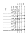
図1は、本発明の実施の形態1による画像表示装置の構成図である。図において、図7と同一部または相当部には同一符号を付し、詳細な説明は省略する。また、18’は外部出力回路、20は制御配線、21a、21bは走査側駆動信号配線、22a、22b、22cは画像側駆動信号配線、23aは走査側スイッチング素子、23bは画像側スイッチング素子、24aは走査側出力端子、24bは画像側出力端子、25aは走査側入力端子、25bは画像側入力端子である。
【0025】
図に示すように、液晶パネル内の全てのゲート配線12には走査側スイッチング素子23aが、また全てのソース配線13は画像側スイッチング素子23bが付加されており、走査側スイッチング素子23aおよび画像側スイッチング素子23bは、1本の制御配線20によりその接続が制御されている。
【0026】
また、走査側駆動信号配線21a、21bは、それぞれ偶数番目、奇数番目のゲート配線13に接続されており、さらに走査側出力端子24aに接続されている。また、画像側駆動信号配線22a、22b、22cは、それぞれ(3n+1)番目の全てのソース配線13、(3n+2)番目の全てのソース配線、(3n+3)番目の全てのソース配線13と接続している。ただしここで(3n+1)番目の全てのソース配線13はR(赤)の画素電極と接続し、(3n+2)番目の全てのソース配線13はG(緑)の画素電極と接続し、(3n+3)番目の全てのソース配線13はB(青)の画素電極と接続している。
【0027】
また、走査側スイッチング素子23aにおいて、第1の接続端子27aは接続配線28aを介して走査側駆動信号配線21aまたは21b、加えて走査側出力端子24aに接続されており、第2の接続端子26aは走査側入力端子25aに接続されている。
【0028】
また、画像側スイッチング素子23bにおいて、第3の接続端子27bは接続配線28bを介して画像側駆動信号配線22a、22b、22cおよび画像側入力端子24bに接続されており、第4の接続端子26bは画像側出力端子25bに接続されている。
【0029】
また、外部出力回路18’は、走査側駆動信号配線21a、21bを介して、図1には示さないゲート配線駆動回路にゲート駆動信号を出力し、画像側駆動信号配線22a、22b、22cを介して、図1には示さないソース配線駆動回路にソース駆動信号を出力する。ゲート配線駆動回路は、ゲート駆動信号を受けると、これに基づき走査信号をゲート配線12に出力し、ソース配線駆動回路は、ソース駆動信号を受けると、これに基づき画像信号をソース配線13に出力する。さらに外部出力回路18’は、走査側駆動信号配線21a、21bを介してゲート配線12にゲート検査信号を出力し、画像側駆動信号配線22a、22b、22cを介してソース配線13にソース検査信号を出力する。
【0030】
このような構成を有する本実施の形態による画像表示装置の動作について、以下に説明を行う。
【0031】
はじめに、液晶パネルに、ゲート配線駆動回路およびソース配線駆動回路が実装されていない場合は、制御配線20からの制御信号によって、走査側スイッチング素子23aにおいて、第1の接続端子27aとゲート配線12とを接続し、画像側スイッチング素子23bにおいて、第3の接続端子27bとソース配線13とを接続する。
【0032】
これにより、外部出力回路18’とゲート配線12とは、走査側駆動信号配線21a、21b、補助配線28aおよび走査側スイッチング素子23aを介して直結される。また、外部出力回路18’とソース配線13とは、画像側駆動信号配線22a、22b、22c、補助配線28bおよび画像側スイッチング素子23bを介して直結される。
【0033】
この状態で、外部出力回路18’から、ゲート検査信号を走査側駆動信号配線21a、21bに印加し、ソース検査信号を画像側駆動信号配線22a、22b22cに印加し、さらに図1には示さない対向電極に信号を印加すると、液晶パネルに白・黒・赤(R)・緑(G)・青色(B)のテスト表示を行うことできる。
【0034】
次に、検査終了後、ゲート配線駆動回路およびソース配線駆動回路を実装して、液晶表示パネルを完成させる場合には、制御配線20からの制御信号によって、走査側スイッチング素子23aにおいて、第2の接続端子26aとゲート配線12とを接続し、画像側スイッチング素子23bにおいて、第4の接続端子26bとソース配線13とを接続する。
【0035】
さらにゲート配線駆動回路の入力端子を走査側出力端子24aに、出力端子を走査側入力端子25aに接続する。また、ソース配線駆動回路の入力端子を画像側出力端子24bに、出力端子を画像側入力端子25bに接続する。
【0036】
これにより、外部出力回路18’とゲート配線12とは、ゲート配線駆動回路を介して接続される。また、外部出力回路18’とソース配線13とは、ソース配線駆動回路を介して接続される。
【0037】
この状態で、外部出力回路18’から、走査側駆動信号を走査側駆動信号配線21a、21bに印加し、画像側駆動信号を画像側駆動信号配線22a、22b22cに印加し、さらに図1には示さない対向電極に信号を印加すると、通常の画像表示を行うことができる。
【0038】
このように、本実施の形態によれば、外部出力回路18’から直結して得られる検査信号による、テスト用の液晶パネル表示と、ゲート配線駆動回路およびソース配線駆動回路を使った、通常の液晶パネル表示が別々にできるため、液晶パネルに線欠陥等が発生したときに、その線欠陥が液晶パネルに起因するのか、それともゲート配線駆動回路、ソース配線駆動回路側の不具合に起因するのかの判断、すなわち要因分離が簡単にできるようになる。
【0039】
さらに、補助配線28a、28bおよびスイッチング素子23a、32bを、ゲート配線駆動回路、ソース配線駆動回路が実装される位置の下部に設けると、液晶パネルの寸法増加を最小限にすることができる。
【0040】
なお、スイッチング素子23a、32bの切り替えは、ゲート配線駆動回路およびソース配線駆動回路の実装前に予め行ってもよい。
【0041】
また、ゲート配線12およびソース配線13と、画像側駆動信号配線との電気的な接続方法は、上記した一例以外にも存在する。たとえば、図2に示すように、画像側スイッチング素子23bの制御を行うため、制御配線20a、20b、20cの3本を用意し、制御配線20aをRのソース配線13に共通して接続し、制御配線20bをGのソース配線13に共通して接続し、制御配線20cをBのソース配線13に共通して接続する。これにより、ソース配線13とスイッチング素子23bを介して接続する画像側駆動信号配線は、画像側駆動信号配線29a、29bの2本とすることができる。また、図3に示すように、画像側駆動信号配線29cのただ一本を各画像側スイッチング素子23bと共通して接続するようにしてもよい。
【0042】
また、走査側スイッチング素子23aの制御配線と、画像側スイッチング素子23bの制御配線とは独立していてもよい。この場合、図4に示すように、外部出力回路18’からは、走査側スイッチング素子23aの制御配線20aと、画像側スイッチング素子23bの制御配線20bを設ける。
【0043】
また、図5に示すように、各ソース配線を三分岐させ、分岐した一本のソース配線のそれぞれに画像側スイッチング素子23bを設け、それぞれを左から順番に画像側スイッチング素子23b(イ)、(ロ)、(ハ)とする。さらに画像側スイッチング素子23b(イ)を共通の制御配線20aで接続し、画像側スイッチング素子23b(ロ)を共通の制御配線20bで接続し、画像側スイッチング素子23b(ハ)を共通の制御配線20cで接続する。
【0044】
また、全ソース配線のうち、(3n+1)番目のソース配線13aと接続した画像側スイッチング素子23b(イ)と、(3n+2)番目のソース配線13bと接続した画像側スイッチング素子23b(ロ)と、(3n+3)番目のソース配線13cと接続した画像側スイッチング素子23b(ハ)とを画像信号配線22a’にて接続し、全ソース配線のうち、(3n+1)番目のソース配線13aと接続した画像側スイッチング素子23b(ロ)および(ハ)と、(3n+2)番目のソース配線13bと接続した画像側スイッチング素子23b(イ)および(ハ)と、(3n+3)番目のソース配線13cと接続した画像側スイッチング素子23b(イ)および(ロ)とを画像信号配線22b’にて接続した構成としてもよい。特にこの構成の場合、ソース配線と接続した画像信号配線を3本から2本に減らすことができ、より狭配線の液晶パネルを実現することができる。
【0045】
また、低温ポリシリコン液晶パネルのように、ゲート配線駆動回路またはソース配線駆動回路の一方が液晶パネルと同一プロセスで作成でき、後に半導体ICとして実装する必要がない場合には、その駆動回路16または17を使用して液晶パネルを表示させることができる。この場合、ゲート配線駆動回路およびソース配線駆動回路として半導体ICを用いない液晶パネルにおいては、対応するゲート配線12またはソース配線13側の、スイッチング素子、補助配線および入出力端子を省略してもよい。
【0046】
(実施の形態2)
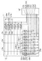
図6は、本発明の実施の形態2による画像表示装置の構成図である。図において、図1と同一部または相当部には同一符号を付し、詳細な説明は省略する。また、30aは走査側バイパス部材、30bは画像側バイパス部材である。
【0047】
図に示すように、液晶パネル内の全てのゲート配線12は走査側入力端子25aに接続され、さらに走査側入力端子25aは、走査側バイパス部材30aを介して走査側出力端子24aおよび走査側駆動信号配線21a、21bに接続している。
【0048】
また、液晶パネル内の全てのソース配線13は画像側入力端子25bに接続され、さらに画像側入力端子25bは、画像側バイパス部材30bを介して画像側出力端子24bおよび画像側駆動信号配線22a、22b、22cに接続している。
【0049】
また、外部出力回路18’は、走査側駆動信号配線21a、21bを介して、図1には示さないゲート配線駆動回路にゲート駆動信号を出力し、画像側駆動信号配線22a、22b、22cを介して、図1には示さないソース配線駆動回路にソース駆動信号を出力する。ゲート配線駆動回路は、ゲート駆動信号を受けると、これに基づき走査信号をゲート配線12に出力し、ソース配線駆動回路は、ソース駆動信号を受けると、これに基づき画像信号をソース配線13に出力する。さらに外部出力回路18’は、走査側駆動信号配線21a、21bを介してゲート配線12にゲート検査信号を出力し、画像側駆動信号配線22a、22b、22cを介してソース配線13にソース検査信号を出力する。
【0050】
このような構成を有する本実施の形態による画像表示装置の動作について、以下に説明を行う。
【0051】
はじめに、液晶パネルに、ゲート配線駆動回路およびソース配線駆動回路が実装されていない場合は、外部出力回路18’とゲート配線12とは、走査側駆動信号配線21a、21bおよび走査側バイパス部材30aを介して接続されている。また、外部出力回路18’とソース配線13とは、画像側駆動信号配線22a、22b、22cおよび画像側バイパス部材30bを介して直結されている。
【0052】
この状態で、外部出力回路18’から、ゲート検査信号を走査側駆動信号配線21a、21bに印加し、実施の形態1と同様にして、液晶パネルに白・黒・赤(R)・緑(G)・青色(B)のテスト表示を行うことができる。
【0053】
次に、検査終了後、ゲート配線駆動回路およびソース配線駆動回路を実装して、液晶表示パネルを完成させる場合には、走査側バイパス部材30aを、走査側入力端子25aと、走査側出力端子24aおよび走査側信号駆動配線21a、21bの接続点との間にて切断し、画像側バイパス部材30bを、画像側入力端子25bと、画像側出力端子24bおよび画像側信号駆動配線22a、22b、22cの接続点との間にて切断し、走査側出力端子24aと走査側信号駆動配線21a、21bおよび走査側入力端子25aとの導通、画像側出力端子24bと画像側信号駆動配線22a、22b、22cおよび画像側入力端子25bとの導通を遮断する。
【0054】
この状態で、ゲート配線駆動回路の入力端子を走査側出力端子24aに、出力端子を走査側入力端子25aに接続し、ソース配線駆動回路の入力端子を画像側出力端子24bに、出力端子を画像側入力端子25bに接続する。
【0055】
これにより外部出力回路18’とゲート配線12とは、ゲート配線駆動回路を介して接続される。また、外部出力回路18’とソース配線13とは、ソース配線駆動回路を介して接続される。
【0056】
これにより、テスト表示が終了した後、ゲート配線駆動回路およびソース配線駆動回路を実装して、通常動作を行わせることができる。この時に液晶パネルに表示の不具合が生じるとすれば、実装したゲート配線駆動回路、ソース配線駆動回路にその原因があると判断することができる。
【0057】
このように、本実施の形態によれば、実施の形態1のスイッチング素子のような構成が不必要になり、より液晶パネルの寸法を小さくできる。
【0058】
なお、走査側バイパス部材30aおよび画像側バイパス部材30bの切断には、レーザーを照射して配線を焼き切る方法や、カッター等の機械的な方法で切断する方法があるが、切断するための幅が必要であるため、液晶パネルの寸法がかえって大きくなってしまう。
【0059】
そこで、走査側バイパス部材30aおよび画像側バイパス部材30bの切断部分31の構成は、膜厚を極端に薄くした薄膜部として、ゲート配線駆動回路およびソース配線駆動回路を実装する時の熱と圧力で、膜厚が薄い薄膜部を切断する。
【0060】
また、切断部分31としては、薄膜部の代わりに、極端に細い、耐電圧の低い極細配線を設け、ゲート配線駆動回路およびソース配線駆動回路を実装する前に、走査側信号駆動配線21a、21bおよび画像側信号駆動配線22a、22b、22cとゲート配線12およびソース配線13との間に10V以上の高電圧を印加し、極細配線を発熱させて切断する。このとき、走査側入力端子25a、画像側入力端子25bは接地するようにする。これによれば、高電位の印加によるゲート配線12およびソース配線13の線欠陥、断線等を防ぐことができる。
【0061】
なお、上記の実施の形態において、ガラス基板11は本発明の基板に相当する。また、走査側スイッチング素子23aは、本発明の第1のスイッチング素子に相当し、画像側スイッチング素子23bおよび23b(イ)(ロ)(ハ)は、本発明の第2のスイッチング素子に相当する。また、走査側スイッチング素子23aおよび接続配線28aは本発明の走査側バイパス配線に相当する。また、ソース信号線13aは本発明のR側のソース配線に、また、ソース信号線13bは本発明のG側のソース配線に、また、ソース信号線13cは本発明のB側のソース配線にそれぞれ相当する。
【0062】
また、画像側スイッチング素子23b(イ)に接続したソース信号線13a、ソース信号線13b、ソース信号線13cの分岐線は、本発明の第1の分岐ソース配線に相当し、画像側スイッチング素子23b(ロ)に接続したソース信号線13a、ソース信号線13b、ソース信号線13cの分岐線は、本発明の第2の分岐ソース配線に相当し、画像側スイッチング素子23b(ハ)に接続したソース信号線13a、ソース信号線13b、ソース信号線13cの分岐線は、本発明の第3の分岐ソース配線に相当する。
【0063】
また、画像側スイッチング素子23bおよび接続配線28bは本発明の画像側バイパス配線に相当する。また、走査側駆動信号線21aは本発明の第1のサブ信号線に相当し、走査側駆動信号線21bは本発明の第2のサブ信号線に相当する。また、画像側駆動信号線22aは本発明の第3のサブ信号線に相当し、画像側駆動信号線22bは本発明の第4のサブ信号線に相当し、画像側駆動信号線22cは本発明の第5のサブ信号線に相当する。
【0064】
また、画像側駆動信号線29a、29b、29cは本発明の第6のサブ信号線に相当し、画像信号配線22a’は本発明の2本のサブ信号線の一方に、また画像信号配線22b’は本発明の2本のサブ信号線の他方に相当し、制御配線20a、20b、20cは、それぞれ本発明の第1の制御線、第2の制御線、第3の制御線に相当する。また、外部出力回路18’は本発明の元信号供給手段に相当する。
【0065】
また、上記の各実施の形態において、画像表示パネルは液晶パネルであるとして説明を行ったが、本発明の画像表示パネルは、プラズマディスプレイパネルやELディスプレイパネルなど、他の表示手段を有するパネルであってもよい。
【0066】
また、本発明は、表示テスト実行前のゲート配線駆動回路およびソース配線駆動回路を省いた画像表示パネルであってもよい。
【0067】
また、本発明は、本発明の画像表示パネルを搭載した画像表示装置であってもよい。
【0068】
【発明の効果】
以上説明したところから明らかなように、本発明により、外部の検査信号出力用の手段を用いずに画像パネルをテスト表示させることができ、パネルの寸法増加を最小限にすることができる。
【図面の簡単な説明】
【図1】本発明の実施の形態1による液晶表示装置の構成図である。
【図2】本発明の実施の形態1による液晶表示装置の他の構成例を示す図である。
【図3】本発明の実施の形態1による液晶表示装置の他の構成例を示す図である。
【図4】本発明の実施の形態1による液晶表示装置の他の構成例を示す図である。
【図5】本発明の実施の形態1による液晶表示装置の他の構成例を示す図である。
【図6】本発明の実施の形態2による液晶表示装置の構成図である。
【図7】従来の技術による液晶パネルの一例を示す図である。
【符号の説明】
11 ガラス基板
12 ゲート配線
13 ソース配線
14 画素電極
15 スイッチング素子
16 ゲート配線駆動回路
17 ソース配線駆動回路
18 外部回路
18’ 外部出力回路
19 配線
20、20a、20b、20c 制御配線
21a、21b 走査側駆動信号配線
22a、22b、22c 画像側駆動信号配線
23a 走査側スイッチング素子
23b 画像側スイッチング素子
24a 走査側出力端子
24b 画像側出力端子
25a 走査側入力端子
25b 画像側入力端子
26a 第2の接続端子
26b 第4の接続端子
27a 第1の接続端子
27b 第3の接続端子
28a、28b 接続配線[0001]
BACKGROUND OF THE INVENTION
The present invention relates to the structure of an image display panel such as a liquid crystal panel.
[0002]
[Prior art]
Liquid crystal panels have the advantages of small size and light weight and low power consumption, and are actively used as monitors for notebook PCs and car navigation systems. Among them, active matrix type TFT liquid crystal panels having excellent contrast and response speed are frequently used.
[0003]
An example of this liquid crystal panel is shown in FIG. In the figure, 11 is a glass substrate, 12 is a gate wiring, 13 is a source wiring, and 14 is a pixel electrode. A
[0004]
Although not shown in the figure, the
[0005]
[Problems to be solved by the invention]
In order to inspect whether the liquid crystal panel operates normally, it is necessary to connect the gate
[0006]
Therefore, at the time of inspecting the liquid crystal panel, before mounting the semiconductor IC which is the gate
[0007]
However, for this purpose, it is necessary to add an inspection wiring in which a plurality of
[0008]
The present invention has been made in view of the above problems, and can perform a display inspection without using an external inspection signal output device, and can reduce the size of the liquid crystal panel. Painting An object of the present invention is to provide an image display panel manufacturing method, an image display panel, and an image display device.
[0009]
[Means for Solving the Problems]
In order to achieve the above object, a first aspect of the present invention (corresponding to claim 1) includes a substrate, a plurality of gate wirings provided on the substrate, and the plurality of gate wirings provided on the substrate. A plurality of source lines crossing the gate lines in a matrix, a plurality of pixel driving electrodes connected to the gate lines and the source lines, and a scanning line driving circuit for outputting a scanning signal to the gate lines An image display panel having a scanning side driving signal wiring for supplying a driving signal and an image side driving signal wiring for supplying an image side driving signal to an image line driving circuit for outputting an image signal to the source wiring. Le Leave
A scanning-side bypass wiring connecting the gate wiring and the scanning-side drive signal wiring;
At least one of image source bypass wiring that connects the source wiring and the image side drive signal wiring,
The scanning side driving signal wiring is supplied with a scanning side driving signal or a gate inspection signal,
An image display panel to which an image side drive signal or a source inspection signal is supplied is connected to the image side drive signal wiring. Le is there.
[0010]
According to a second aspect of the present invention (corresponding to claim 2), one end is connected to the gate wiring and the other end is provided on the scanning side bypass wiring, and the other end is a first connection terminal and a second connection terminal. A plurality of first switching elements selectively connected to any one of
Provided on the image-side bypass wiring, one end is connected to the source wiring, and the other end is selectively connected to either the third connection terminal or the fourth connection terminal. A switching element,
The first connection terminal is connected to the scanning side drive signal line, and the third connection terminal is connected to the image side drive signal line. Le is there.
[0011]
According to a third aspect of the present invention (corresponding to claim 3), the plurality of gate wiring lines are 2m (m is an integer of 1 or more) corresponding to the odd-numbered one and the even-numbered one, respectively. ,
The plurality of source wirings are a total of 3n (n: an integer of 1 or more), a set of three for the R pixel electrode, the G pixel electrode, and the B pixel electrode,
The scanning side drive signal line includes a first sub signal line connected in common to the odd-numbered gate lines and a second sub signal line connected in common to the even-numbered gate lines. Have
The image side drive signal wiring includes a third sub signal line commonly connected to the R source wirings, a fourth sub signal line commonly connected to the G source wirings, And a fifth sub signal line connected in common to the source wiring of each B. Le is there.
[0012]
According to a fourth aspect of the present invention (corresponding to claim 4), the first switching element and the second switching element are controlled by a common control line. Image display panel Le is there.
[0013]
According to a fifth aspect of the present invention (corresponding to claim 5), the first switching element and the second switching element are respectively controlled by control lines independent from each other. Display panel Le is there.
[0014]
According to a sixth aspect of the present invention (corresponding to claim 6), the plurality of gate wiring lines are 2m (m is an integer of 1 or more) corresponding to the odd-numbered one and the even-numbered one, respectively. ,
The plurality of source wirings are a total of 3n (n: an integer of 1 or more), a set of three for the R pixel electrode, the G pixel electrode, and the B pixel electrode,
The scanning side drive signal line includes a first sub signal line connected in common to the odd-numbered gate lines and a second sub signal line connected in common to the even-numbered gate lines. Have
The image-side drive signal wiring is connected in common to at least any two of the R source wirings, the G source wirings, and the B source wirings. Sub signal lines,
The second switching element connected to the source wiring of each R is controlled by a common first control line,
The second switching element connected to the source wiring of each G is controlled by a common second control line,
The second switching element connected to the source wiring of each B is the image display panel of the second aspect of the present invention controlled by a common third control line. Le is there.
[0015]
According to a seventh aspect of the present invention (corresponding to claim 7), the plurality of gate wiring lines are 2m (m is an integer of 1 or more) corresponding to the odd-numbered one and the even-numbered one, respectively. ,
The plurality of source wirings are a total of 3n (n: an integer of 1 or more), a set of three for the R pixel electrode, the G pixel electrode, and the B pixel electrode,
The image-side drive signal wiring is commonly connected to at least any two of the R source wirings, the G source wirings, and the B source wirings. Sub signal lines,
Each source wiring is branched into first, second, and third branch source wirings,
For the set of three of R, G, and B, the first branch source wiring on the R side, the second branch source wiring on the G side, and the third branch source wiring on the B side are respectively The second sub-signal line is connected to one of the two sub-signal lines via two switching elements, the R-side second and third branch source lines, the G-side first and third branch source lines, and the B The first and second branch source lines on the side are connected to the other of the two sub signal lines through the second switching element,
The second switching element connected to the first branch source wiring on each R, G, B side is controlled by a common first control line,
The second switching element connected to the second source wiring on each R, G, B side is controlled by a common second control line,
The second switching element connected to the third source wiring on each R, G, B side is controlled by a common third control line. Le is there.
[0016]
According to an eighth aspect of the present invention (corresponding to claim 8), a plurality of first output terminals connected to the gate lines and the scan side drive signal lines provided on the scan side bypass lines A first input terminal connected;
A plurality of second output terminals connected to each of the source lines and a second input terminal connected to the image side drive signal lines provided on the image side bypass wiring;
The scanning side bypass wiring has a cut portion between the first output terminal and a connection point between the scanning side driving signal wiring and the first input terminal,
The image-side bypass wiring includes a cut portion between the second output terminal and a connection point between the image-side drive signal wiring and the second input terminal. Le is there.
[0017]
The ninth aspect of the present invention (corresponding to claim 9) is the image display panel according to the eighth aspect of the present invention, wherein the cut portion is a metal thin film or a metal thin wire. Le is there.
[0018]
The tenth aspect of the present invention (corresponding to claim 10) is the image display panel of the first aspect of the present invention. Le Cutting off the conduction of the scanning side bypass wiring and the image side bypass wiring, respectively;
Providing a scanning side driving circuit between the gate wiring and the scanning side driving signal wiring;
And a step of providing an image side drive circuit between the source line and the image side drive signal line.
[0019]
The eleventh aspect of the present invention (corresponding to claim 11) is the image display panel of the second aspect of the present invention. Le Switching the first switching element such that a second connection terminal is selected;
Switching the second switching element such that a fourth connection terminal is selected;
Providing a scanning side drive circuit between the first connection terminal and the gate wiring;
And a step of providing an image-side driving circuit between the third connection terminal and the source wiring.
[0020]
The twelfth aspect of the present invention (corresponding to claim 12) is the 8 The image display panel of the present invention Le The scanning-side bypass wiring and the image-side bypass wiring are equal to or higher than their withstand voltage, and more than any withstand voltage of the gate wiring, the source wiring, the scanning-side driving signal wiring, and the image-side driving signal wiring. Cutting by applying a low voltage;
Providing a scanning side driving circuit between the gate wiring and the scanning side driving signal wiring;
And a step of providing an image side drive circuit between the source line and the image side drive signal line.
[0021]
The thirteenth aspect of the present invention (corresponding to claim 13) is
in front A scanning side driving circuit connected to the gate wiring and the scanning side driving signal wiring;
in front An image side driving circuit connected to the source wiring and the image side driving signal wiring,
in front Running The conduction of the inspection side bypass wiring and the image side bypass wiring is blocked. Of the first invention It is an image display panel.
[0022]
The fourteenth aspect of the present invention (corresponding to claim 14) is the image display panel of the thirteenth aspect of the present invention,
The image display device includes original signal supply means for supplying a scanning side driving signal or a gate inspection signal to the scanning side driving circuit and supplying an image side driving signal or a source inspection signal to the image side driving circuit.
[0023]
DETAILED DESCRIPTION OF THE INVENTION
Hereinafter, embodiments of the present invention will be described with reference to the drawings.
[0024]
(Embodiment 1)
FIG. 1 is a configuration diagram of an image display apparatus according to
[0025]
As shown in the figure, scanning
[0026]
The scanning side
[0027]
In the scanning-
[0028]
In the image
[0029]
Further, the
[0030]
The operation of the image display apparatus according to this embodiment having such a configuration will be described below.
[0031]
First, when the gate wiring driving circuit and the source wiring driving circuit are not mounted on the liquid crystal panel, the first connection terminal 27a, the
[0032]
Thus, the
[0033]
In this state, from the
[0034]
Next, after completion of the inspection, when the gate line driving circuit and the source line driving circuit are mounted to complete the liquid crystal display panel, the
[0035]
Further, the input terminal of the gate wiring driving circuit is connected to the scanning
[0036]
Thereby, the
[0037]
In this state, from the
[0038]
As described above, according to the present embodiment, a normal liquid crystal panel display using a test signal obtained by directly connecting from the
[0039]
Furthermore, if the
[0040]
Note that switching of the
[0041]
Further, there are other methods of electrical connection between the
[0042]
Further, the control wiring of the scanning
[0043]
Further, as shown in FIG. 5, each source wiring is divided into three branches, and an image-
[0044]
Among all the source lines, the image
[0045]
When one of the gate wiring drive circuit and the source wiring drive circuit can be formed by the same process as the liquid crystal panel and it is not necessary to be mounted as a semiconductor IC later, like the low-temperature polysilicon liquid crystal panel, the
[0046]
(Embodiment 2)
FIG. 6 shows an embodiment of the present invention. 2 It is a block diagram of the image display apparatus by. In the figure, the same or corresponding parts as in FIG.
[0047]
As shown in the figure, all the gate lines 12 in the liquid crystal panel are connected to the scanning
[0048]
Further, all the source lines 13 in the liquid crystal panel are connected to the image
[0049]
Further, the
[0050]
The operation of the image display apparatus according to this embodiment having such a configuration will be described below.
[0051]
First, when the gate wiring driving circuit and the source wiring driving circuit are not mounted on the liquid crystal panel, the
[0052]
In this state, a gate inspection signal is applied from the
[0053]
Next, after completion of the inspection, when the liquid crystal display panel is completed by mounting the gate line driving circuit and the source line driving circuit, the scanning
[0054]
In this state, the input terminal of the gate wiring driving circuit is connected to the scanning
[0055]
Thereby, the
[0056]
Thus, after the test display is completed, the gate line driving circuit and the source line driving circuit can be mounted and normal operation can be performed. If a display defect occurs in the liquid crystal panel at this time, it can be determined that the mounted gate wiring driving circuit and source wiring driving circuit have the cause.
[0057]
Thus, according to the present embodiment, the configuration as in the switching element of the first embodiment is unnecessary, and the size of the liquid crystal panel can be further reduced.
[0058]
The scanning
[0059]
Therefore, the configuration of the
[0060]
Further, as the
[0061]
In the above embodiment, the
[0062]
The branch lines of the
[0063]
Further, the image
[0064]
The image side
[0065]
Further, in each of the above embodiments, the image display panel has been described as a liquid crystal panel, but the image display panel of the present invention has been described. Le Panels having other display means such as plasma display panels and EL display panels Le There may be.
[0066]
The present invention also provides an image display panel that omits the gate line drive circuit and the source line drive circuit before the display test. Le There may be.
[0067]
Further, the present invention may be an image display device equipped with the image display panel of the present invention.
[0068]
【The invention's effect】
As is apparent from the above description, according to the present invention, the image panel can be test-displayed without using an external inspection signal output means, and an increase in the size of the panel can be minimized.
[Brief description of the drawings]
FIG. 1 is a configuration diagram of a liquid crystal display device according to a first embodiment of the present invention.
FIG. 2 is a diagram showing another configuration example of the liquid crystal display device according to the first embodiment of the present invention.
FIG. 3 is a diagram showing another configuration example of the liquid crystal display device according to the first embodiment of the present invention.
FIG. 4 is a diagram showing another configuration example of the liquid crystal display device according to the first embodiment of the present invention.
FIG. 5 is a diagram showing another configuration example of the liquid crystal display device according to the first embodiment of the present invention.
FIG. 6 is a configuration diagram of a liquid crystal display device according to a second embodiment of the present invention.
FIG. 7 is a diagram illustrating an example of a liquid crystal panel according to a conventional technique.
[Explanation of symbols]
11 Glass substrate
12 Gate wiring
13 Source wiring
14 Pixel electrode
15 Switching element
16 Gate wiring drive circuit
17 Source wiring Driving circuit
18 External circuit
18 'External output circuit
19 Wiring
20, 20a, 20b, 20c Control wiring
21a, 21b Scan side drive signal wiring
22a, 22b, 22c Image side drive signal wiring
23a Scanning side switching element
23b Image-side switching element
24a Scanning side output terminal
24b Image side output terminal
25a Scanning side input terminal
25b Image side input terminal
26a Second connection terminal
26b Fourth connection terminal
27a First connection terminal
27b Third connection terminal
28a, 28b Connection wiring
Claims (14)
前記ゲート配線と前記走査側駆動信号配線とを接続する走査側バイパス配線と、前記ソース配線と前記画像側駆動信号配線とを接続する画像側バイパス配線とのいずれか一方を少なくとも備え、
前記走査側駆動信号配線には、走査側駆動信号またはゲート検査信号が供給され、
前記画像側駆動信号配線には、画像側駆動信号またはソース検査信号が供給される画像表示パネル。A substrate, a plurality of gate wirings provided on the substrate, a plurality of source wirings provided on the substrate and intersecting the plurality of gate wirings in a matrix, and connected to the gate wiring and the source wiring A plurality of pixel driving electrodes, a scanning side driving signal wiring for supplying a scanning side driving signal to a scanning line driving circuit that outputs a scanning signal to the gate wiring, and an image signal are output to the source wiring. In an image display panel having an image side drive signal wiring for supplying an image side drive signal to the image line drive circuit,
At least one of a scanning side bypass wiring that connects the gate wiring and the scanning side driving signal wiring, and an image side bypass wiring that connects the source wiring and the image side driving signal wiring,
The scanning side driving signal wiring is supplied with a scanning side driving signal or a gate inspection signal,
An image display panel in which an image side drive signal or a source inspection signal is supplied to the image side drive signal wiring.
前記画像側バイパス配線上に設けられた、一端が前記ソース配線と接続され、他端が第3の接続端子と第4の接続端子のいずれかに選択的に接続される、複数の第2のスイッチング素子とを備え、
前記第1の接続端子は前記走査側駆動信号配線と接続され、前記第3の接続端子は前記画像側駆動信号配線と接続された請求項1に記載の画像表示パネル。A plurality of first terminals provided on the scanning side bypass wiring, one end of which is connected to the gate wiring and the other end is selectively connected to either the first connection terminal or the second connection terminal. A switching element;
Provided on the image-side bypass wiring, one end is connected to the source wiring, and the other end is selectively connected to either the third connection terminal or the fourth connection terminal. A switching element,
The image display panel according to claim 1, wherein the first connection terminal is connected to the scanning side drive signal wiring, and the third connection terminal is connected to the image side drive signal wiring.
前記複数のソース配線は、Rの画素電極用、Gの画素電極用およびBの画素電極用で3本一組の計3n(n:1以上の整数)本であり、
前記走査側駆動信号配線は、前記奇数番目のゲート配線に共通して接続された第1のサブ信号線と、前記偶数番目のゲート配線に共通して接続された第2のサブ信号線とを有し、
前記画像側駆動信号配線は、各Rの前記ソース配線に共通して接続された第3のサブ信号線と、各Gの前記ソース配線に共通して接続された第4のサブ信号線と、各Bの前記ソース配線に共通して接続された第5のサブ信号線とを有する請求項2に記載の画像表示パネル。The plurality of gate wirings are 2m (m: an integer of 1 or more) corresponding to the odd-numbered and even-numbered ones,
The plurality of source wirings are a total of 3n (n: an integer of 1 or more), a set of three for the R pixel electrode, the G pixel electrode, and the B pixel electrode,
The scanning side drive signal line includes a first sub signal line connected in common to the odd-numbered gate lines and a second sub signal line connected in common to the even-numbered gate lines. Have
The image side drive signal wiring includes a third sub signal line commonly connected to the R source wirings, a fourth sub signal line commonly connected to the G source wirings, The image display panel according to claim 2, further comprising a fifth sub signal line connected in common to the source wiring of each B.
前記複数のソース配線は、Rの画素電極用、Gの画素電極用およびBの画素電極用で3本一組の計3n(n:1以上の整数)本であり、
前記走査側駆動信号配線は、前記奇数番目のゲート配線に共通して接続された第1のサブ信号線と、前記偶数番目のゲート配線に共通して接続された第2のサブ信号線とを有し、
前記画像側駆動信号配線は、各Rの前記ソース配線と、各Gの前記ソース配線と、各Bの前記ソース配線のうち、少なくともいずれかの2種類の配線に共通して接続された第6のサブ信号線を有し、
各Rの前記ソース配線に接続された前記第2のスイッチング素子は、共通の第1の制御線によって制御され、
各Gの前記ソース配線に接続された前記第2のスイッチング素子は、共通の第2の制御線によって制御され、
各Bの前記ソース配線に接続された前記第2のスイッチング素子は、共通の第3の制御線によって制御される請求項2に記載の画像表示パネル。The plurality of gate wirings are 2m (m: an integer of 1 or more) corresponding to the odd-numbered and even-numbered ones,
The plurality of source wirings are a total of 3n (n: an integer of 1 or more), a set of three for the R pixel electrode, the G pixel electrode, and the B pixel electrode,
The scanning side drive signal line includes a first sub signal line connected in common to the odd-numbered gate lines and a second sub signal line connected in common to the even-numbered gate lines. Have
The image-side drive signal wiring is connected in common to at least any two of the R source wirings, the G source wirings, and the B source wirings. Sub signal lines,
The second switching element connected to the source wiring of each R is controlled by a common first control line,
The second switching element connected to the source wiring of each G is controlled by a common second control line,
The image display panel according to claim 2, wherein the second switching element connected to the source wiring of each B is controlled by a common third control line.
前記複数のソース配線は、Rの画素電極用、Gの画素電極用およびBの画素電極用で3本一組の計3n(n:1以上の整数)本であり、
前記画像側駆動信号配線は、各Rの前記ソース配線と、各Gの前記ソース配線と、各Bの前記ソース配線のうち、少なくともいずれかの2種類の配線に共通して接続された2本のサブ信号線を有し、
各ソース配線は、第1,第2,第3の分岐ソース配線に分岐しており、
前記R、G、Bの3本一組について、前記R側の第1の分岐ソース配線、前記G側の第2の分岐ソース配線、前記B側の第3の分岐ソース配線は、それぞれ前記第2のスイッチング素子を介して前記2本のサブ信号線の一方と接続し、前記R側の第2および第3の分岐ソース配線、前記G側の第1および第3の分岐ソース配線、前記B側の第1および第2の分岐ソース配線は、それぞれ前記第2のスイッチング素子を介して前記2本のサブ信号線の他方と接続し、
各R、G、B側の前記第1の分岐ソース配線に接続された前記第2のスイッチング素子は、共通の第1の制御線によって制御され、
各R、G、B側の前記第2のソース配線に接続された前記第2のスイッチング素子は、共通の第2の制御線によって制御され、
各R、G、B側の前記第3のソース配線に接続された前記第2のスイッチング素子は、共通の第3の制御線によって制御される請求項2に記載の画像表示パネル。The plurality of gate wirings are 2m (m: an integer of 1 or more) corresponding to the odd-numbered and even-numbered ones,
The plurality of source wirings are a total of 3n (n: an integer of 1 or more), a set of three for the R pixel electrode, the G pixel electrode, and the B pixel electrode,
The image-side drive signal wiring is commonly connected to at least any two of the R source wirings, the G source wirings, and the B source wirings. Sub signal lines,
Each source wiring is branched into first, second, and third branch source wirings,
For the set of three of R, G, and B, the first branch source wiring on the R side, the second branch source wiring on the G side, and the third branch source wiring on the B side are respectively The second sub-signal line is connected to one of the two sub-signal lines via two switching elements, the R-side second and third branch source lines, the G-side first and third branch source lines, and the B The first and second branch source lines on the side are connected to the other of the two sub signal lines through the second switching element,
The second switching element connected to the first branch source wiring on each R, G, B side is controlled by a common first control line,
The second switching element connected to the second source wiring on each R, G, B side is controlled by a common second control line,
The image display panel according to claim 2, wherein the second switching element connected to the third source line on each R, G, B side is controlled by a common third control line.
前記画像側バイパス配線上に設けられた、各前記ソース配線と接続される複数の第2の出力端子および前記画像側駆動信号配線と接続された第2の入力端子とを備え、
前記走査側バイパス配線は、前記第1の出力端子と、前記走査側駆動信号配線および第1の入力端子の接続点との間に切断部分を有し、
前記走査側バイパス配線は、前記第2の出力端子と、前記画像側駆動信号配線および第2の入力端子の接続点との間に切断部分を有する請求項1に記載の画像表示パネル。A plurality of first output terminals connected to the gate wirings and a first input terminal connected to the scanning drive signal wirings provided on the scanning side bypass wiring;
A plurality of second output terminals connected to each of the source lines and a second input terminal connected to the image side drive signal lines provided on the image side bypass wiring;
The scanning side bypass wiring has a cut portion between the first output terminal and a connection point between the scanning side driving signal wiring and the first input terminal,
The image display panel according to claim 1, wherein the scanning-side bypass wiring has a cut portion between the second output terminal and a connection point between the image-side driving signal wiring and the second input terminal.
前記ゲート配線と前記走査側駆動信号配線との間に走査側駆動回路を設ける工程と、
前記ソース配線と前記画像側駆動信号配線との間に画像側駆動回路を設ける工程とを備えた画像表示パネルの製造方法。Cutting off conduction of the scanning side bypass wiring and the image side bypass wiring of the image display panel according to claim 1;
Providing a scanning side driving circuit between the gate wiring and the scanning side driving signal wiring;
And a step of providing an image side drive circuit between the source line and the image side drive signal line.
前記第2のスイッチング素子を、第4の接続端子が選択されるように切り換える工程と、
前記第1の接続端子と前記ゲート配線との間に走査側駆動回路を設ける工程と、
前記第3の接続端子と前記ソース配線との間に画像側駆動回路を設ける工程とを備えた画像表示パネルの製造方法。Switching the first switching element of the image display panel according to claim 2 so that a second connection terminal is selected;
Switching the second switching element such that a fourth connection terminal is selected;
Providing a scanning side drive circuit between the first connection terminal and the gate wiring;
And a step of providing an image side drive circuit between the third connection terminal and the source wiring.
前記ゲート配線と前記走査側駆動信号配線との間に走査側駆動回路を設ける工程と、
前記ソース配線と前記画像側駆動信号配線との間に画像側駆動回路を設ける工程とを備えた画像表示パネルの製造方法。9. The scanning side bypass wiring and the image side bypass wiring of the image display panel according to claim 8, wherein the gate side wiring, the source wiring, the scanning side driving signal wiring, and the image side Cutting by applying a voltage lower than any withstand voltage of the drive signal wiring; and
Providing a scanning side driving circuit between the gate wiring and the scanning side driving signal wiring;
And a step of providing an image side drive circuit between the source line and the image side drive signal line.
前記ソース配線および前記画像側駆動信号配線と接続された画像側駆動回路とを備え、
前記走査側バイパス配線および前記画像側バイパス配線の導通は、それぞれ遮断されている、請求項1に記載の画像表示パネル。A scanning side driving circuit connected to the gate wiring and the scanning side driving signal wiring;
An image side driving circuit connected to the source wiring and the image side driving signal wiring;
The image display panel according to claim 1, wherein conduction of the scanning side bypass wiring and the image side bypass wiring is blocked.
前記走査側駆動回路に走査側駆動信号またはゲート検査信号を供給するとともに、前記画像側駆動回路に画像側駆動信号またはソース検査信号を供給する元信号供給手段を備えた画像表示装置。An image display panel according to claim 13,
An image display device comprising original signal supply means for supplying a scanning side driving signal or a gate inspection signal to the scanning side driving circuit and supplying an image side driving signal or a source inspection signal to the image side driving circuit.
Priority Applications (1)
| Application Number | Priority Date | Filing Date | Title |
|---|---|---|---|
| JP2002024429A JP4141696B2 (en) | 2002-01-31 | 2002-01-31 | Image display panel, manufacturing method thereof, and image display device |
Applications Claiming Priority (1)
| Application Number | Priority Date | Filing Date | Title |
|---|---|---|---|
| JP2002024429A JP4141696B2 (en) | 2002-01-31 | 2002-01-31 | Image display panel, manufacturing method thereof, and image display device |
Publications (3)
| Publication Number | Publication Date |
|---|---|
| JP2003228298A JP2003228298A (en) | 2003-08-15 |
| JP2003228298A5 JP2003228298A5 (en) | 2005-08-11 |
| JP4141696B2 true JP4141696B2 (en) | 2008-08-27 |
Family
ID=27746873
Family Applications (1)
| Application Number | Title | Priority Date | Filing Date |
|---|---|---|---|
| JP2002024429A Expired - Fee Related JP4141696B2 (en) | 2002-01-31 | 2002-01-31 | Image display panel, manufacturing method thereof, and image display device |
Country Status (1)
| Country | Link |
|---|---|
| JP (1) | JP4141696B2 (en) |
Families Citing this family (6)
| Publication number | Priority date | Publication date | Assignee | Title |
|---|---|---|---|---|
| KR100385082B1 (en) * | 2000-07-27 | 2003-05-22 | 삼성전자주식회사 | a liquid crystal display and a manufacturing method thereof |
| JP5140999B2 (en) * | 2006-11-22 | 2013-02-13 | カシオ計算機株式会社 | Liquid crystal display |
| JP4947801B2 (en) | 2007-02-08 | 2012-06-06 | 東芝モバイルディスプレイ株式会社 | Liquid crystal display |
| JP5164669B2 (en) * | 2008-05-28 | 2013-03-21 | 株式会社ジャパンディスプレイウェスト | Electro-optical panel, electro-optical device, and electronic apparatus equipped with the same |
| CN102687188B (en) * | 2010-01-19 | 2015-01-14 | 夏普株式会社 | Display panel and inspection method thereof |
| CN106019672A (en) * | 2016-07-26 | 2016-10-12 | 武汉华星光电技术有限公司 | Making method for thin film transistor array substrate |
-
2002
- 2002-01-31 JP JP2002024429A patent/JP4141696B2/en not_active Expired - Fee Related
Also Published As
| Publication number | Publication date |
|---|---|
| JP2003228298A (en) | 2003-08-15 |
Similar Documents
| Publication | Publication Date | Title |
|---|---|---|
| KR101241761B1 (en) | Drive chip, display device having the same and method for repairing | |
| US9568791B2 (en) | Liquid crystal display device | |
| KR100265150B1 (en) | Tftlcd active data line repair instrument and method | |
| US7636077B2 (en) | Backup shift register module for a gateline driving circuit | |
| US6903717B2 (en) | Display device having driving circuit | |
| US7106295B2 (en) | Liquid crystal display device | |
| JP5285119B2 (en) | Active matrix substrate, display device, active matrix substrate inspection method, and display device inspection method | |
| TWI398712B (en) | Thin film transistor array panel with improved connection to test lines | |
| JP2004310024A (en) | Liquid crystal display device and its inspecting method | |
| JP2004310024A5 (en) | ||
| KR20090072393A (en) | Display apparatus and method of driving therefor | |
| JP2002202758A (en) | Display device | |
| JP4141696B2 (en) | Image display panel, manufacturing method thereof, and image display device | |
| CN108538863B (en) | Display substrate, repairing method thereof and display device | |
| JP3664573B2 (en) | Liquid crystal display | |
| CN101726943B (en) | Active component array substrate, liquid-crystal display panel and detection method for both | |
| JPH0667200A (en) | Liquid crystal display device | |
| KR101472130B1 (en) | Liquid crystal display device | |
| JPH09258249A (en) | Semiconductor integrated circuit | |
| JPH1152928A (en) | Liquid crystal driving device | |
| JPH06222741A (en) | Driving method for liquid crystal display device and driving circuit | |
| JP2005107382A (en) | Display device | |
| JP2000105576A (en) | Liquid crystal display device and lsi element for driving signal line | |
| JPH05307167A (en) | Active matrix panel | |
| JP4690595B2 (en) | Image display panel member test method, image display panel member, and image display panel |
Legal Events
| Date | Code | Title | Description |
|---|---|---|---|
| A521 | Written amendment |
Free format text: JAPANESE INTERMEDIATE CODE: A523 Effective date: 20050126 |
|
| A621 | Written request for application examination |
Free format text: JAPANESE INTERMEDIATE CODE: A621 Effective date: 20050126 |
|
| A711 | Notification of change in applicant |
Free format text: JAPANESE INTERMEDIATE CODE: A711 Effective date: 20061207 |
|
| A977 | Report on retrieval |
Free format text: JAPANESE INTERMEDIATE CODE: A971007 Effective date: 20061222 |
|
| A131 | Notification of reasons for refusal |
Free format text: JAPANESE INTERMEDIATE CODE: A131 Effective date: 20070925 |
|
| A521 | Written amendment |
Free format text: JAPANESE INTERMEDIATE CODE: A523 Effective date: 20071121 |
|
| A131 | Notification of reasons for refusal |
Free format text: JAPANESE INTERMEDIATE CODE: A131 Effective date: 20080129 |
|
| A521 | Written amendment |
Free format text: JAPANESE INTERMEDIATE CODE: A523 Effective date: 20080328 |
|
| TRDD | Decision of grant or rejection written | ||
| A01 | Written decision to grant a patent or to grant a registration (utility model) |
Free format text: JAPANESE INTERMEDIATE CODE: A01 Effective date: 20080603 |
|
| A01 | Written decision to grant a patent or to grant a registration (utility model) |
Free format text: JAPANESE INTERMEDIATE CODE: A01 |
|
| A61 | First payment of annual fees (during grant procedure) |
Free format text: JAPANESE INTERMEDIATE CODE: A61 Effective date: 20080611 |
|
| FPAY | Renewal fee payment (event date is renewal date of database) |
Free format text: PAYMENT UNTIL: 20110620 Year of fee payment: 3 |
|
| R150 | Certificate of patent or registration of utility model |
Ref document number: 4141696 Country of ref document: JP Free format text: JAPANESE INTERMEDIATE CODE: R150 Free format text: JAPANESE INTERMEDIATE CODE: R150 |
|
| S533 | Written request for registration of change of name |
Free format text: JAPANESE INTERMEDIATE CODE: R313533 |
|
| FPAY | Renewal fee payment (event date is renewal date of database) |
Free format text: PAYMENT UNTIL: 20110620 Year of fee payment: 3 |
|
| R350 | Written notification of registration of transfer |
Free format text: JAPANESE INTERMEDIATE CODE: R350 |
|
| FPAY | Renewal fee payment (event date is renewal date of database) |
Free format text: PAYMENT UNTIL: 20120620 Year of fee payment: 4 |
|
| S531 | Written request for registration of change of domicile |
Free format text: JAPANESE INTERMEDIATE CODE: R313531 |
|
| FPAY | Renewal fee payment (event date is renewal date of database) |
Free format text: PAYMENT UNTIL: 20120620 Year of fee payment: 4 |
|
| R350 | Written notification of registration of transfer |
Free format text: JAPANESE INTERMEDIATE CODE: R350 |
|
| FPAY | Renewal fee payment (event date is renewal date of database) |
Free format text: PAYMENT UNTIL: 20120620 Year of fee payment: 4 |
|
| FPAY | Renewal fee payment (event date is renewal date of database) |
Free format text: PAYMENT UNTIL: 20130620 Year of fee payment: 5 |
|
| S533 | Written request for registration of change of name |
Free format text: JAPANESE INTERMEDIATE CODE: R313533 |
|
| FPAY | Renewal fee payment (event date is renewal date of database) |
Free format text: PAYMENT UNTIL: 20130620 Year of fee payment: 5 |
|
| R350 | Written notification of registration of transfer |
Free format text: JAPANESE INTERMEDIATE CODE: R350 |
|
| FPAY | Renewal fee payment (event date is renewal date of database) |
Free format text: PAYMENT UNTIL: 20140620 Year of fee payment: 6 |
|
| R250 | Receipt of annual fees |
Free format text: JAPANESE INTERMEDIATE CODE: R250 |
|
| R250 | Receipt of annual fees |
Free format text: JAPANESE INTERMEDIATE CODE: R250 |
|
| R250 | Receipt of annual fees |
Free format text: JAPANESE INTERMEDIATE CODE: R250 |
|
| R250 | Receipt of annual fees |
Free format text: JAPANESE INTERMEDIATE CODE: R250 |
|
| R250 | Receipt of annual fees |
Free format text: JAPANESE INTERMEDIATE CODE: R250 |
|
| R250 | Receipt of annual fees |
Free format text: JAPANESE INTERMEDIATE CODE: R250 |
|
| R250 | Receipt of annual fees |
Free format text: JAPANESE INTERMEDIATE CODE: R250 |
|
| S111 | Request for change of ownership or part of ownership |
Free format text: JAPANESE INTERMEDIATE CODE: R313111 |
|
| LAPS | Cancellation because of no payment of annual fees | ||
| R350 | Written notification of registration of transfer |
Free format text: JAPANESE INTERMEDIATE CODE: R350 |