JP4138494B2 - Optimized multilayer optical waveguide system - Google Patents
Optimized multilayer optical waveguide system Download PDFInfo
- Publication number
- JP4138494B2 JP4138494B2 JP2002586040A JP2002586040A JP4138494B2 JP 4138494 B2 JP4138494 B2 JP 4138494B2 JP 2002586040 A JP2002586040 A JP 2002586040A JP 2002586040 A JP2002586040 A JP 2002586040A JP 4138494 B2 JP4138494 B2 JP 4138494B2
- Authority
- JP
- Japan
- Prior art keywords
- layer
- core
- refractive index
- buffer layer
- light transmissive
- Prior art date
- Legal status (The legal status is an assumption and is not a legal conclusion. Google has not performed a legal analysis and makes no representation as to the accuracy of the status listed.)
- Expired - Fee Related
Links
Images


Classifications
-
- G—PHYSICS
- G02—OPTICS
- G02B—OPTICAL ELEMENTS, SYSTEMS OR APPARATUS
- G02B6/00—Light guides; Structural details of arrangements comprising light guides and other optical elements, e.g. couplings
- G02B6/02—Optical fibres with cladding with or without a coating
-
- G—PHYSICS
- G02—OPTICS
- G02B—OPTICAL ELEMENTS, SYSTEMS OR APPARATUS
- G02B6/00—Light guides; Structural details of arrangements comprising light guides and other optical elements, e.g. couplings
- G02B6/10—Light guides; Structural details of arrangements comprising light guides and other optical elements, e.g. couplings of the optical waveguide type
- G02B6/12—Light guides; Structural details of arrangements comprising light guides and other optical elements, e.g. couplings of the optical waveguide type of the integrated circuit kind
- G02B6/122—Basic optical elements, e.g. light-guiding paths
- G02B6/1221—Basic optical elements, e.g. light-guiding paths made from organic materials
-
- G—PHYSICS
- G02—OPTICS
- G02B—OPTICAL ELEMENTS, SYSTEMS OR APPARATUS
- G02B6/00—Light guides; Structural details of arrangements comprising light guides and other optical elements, e.g. couplings
- G02B6/10—Light guides; Structural details of arrangements comprising light guides and other optical elements, e.g. couplings of the optical waveguide type
- G02B6/12—Light guides; Structural details of arrangements comprising light guides and other optical elements, e.g. couplings of the optical waveguide type of the integrated circuit kind
- G02B6/13—Integrated optical circuits characterised by the manufacturing method
-
- G—PHYSICS
- G02—OPTICS
- G02B—OPTICAL ELEMENTS, SYSTEMS OR APPARATUS
- G02B6/00—Light guides; Structural details of arrangements comprising light guides and other optical elements, e.g. couplings
- G02B6/10—Light guides; Structural details of arrangements comprising light guides and other optical elements, e.g. couplings of the optical waveguide type
- G02B6/12—Light guides; Structural details of arrangements comprising light guides and other optical elements, e.g. couplings of the optical waveguide type of the integrated circuit kind
- G02B2006/12083—Constructional arrangements
- G02B2006/12107—Grating
-
- G—PHYSICS
- G02—OPTICS
- G02B—OPTICAL ELEMENTS, SYSTEMS OR APPARATUS
- G02B6/00—Light guides; Structural details of arrangements comprising light guides and other optical elements, e.g. couplings
- G02B6/10—Light guides; Structural details of arrangements comprising light guides and other optical elements, e.g. couplings of the optical waveguide type
- G02B6/12—Light guides; Structural details of arrangements comprising light guides and other optical elements, e.g. couplings of the optical waveguide type of the integrated circuit kind
- G02B2006/12166—Manufacturing methods
- G02B2006/12176—Etching
Description
本発明は、平面型すなわち「一体型」の光導波路に関し、および特に、有機およびポリマー材料を用いてリソグラフィーにより形成されたシングルモードの光導波路に関する。 The present invention relates to planar or “integrated” optical waveguides, and in particular to single mode optical waveguides formed by lithography using organic and polymeric materials.
多層光導波路構造は、光ファイバー通信システム内の光信号をルーティングおよび制御するのに用いられる一体型の光回路を構築するのに用いられる。光通信システムにおいて、メッセージは、レーザおよび発光ダイオードのような源を用いて生成される搬送波によって赤外光学波長において送信される。これらの光通信システムは興味深いものである。なぜなら、それら光通信システムは、銅線または同軸ケーブルを用いる電子的通信システムに優るいくつかの利点を提供するからである。それらは、電子的システムよりもメッセージを高速に送信する能力と同様に、非常に多くの数の通信チャネルを有する。 Multilayer optical waveguide structures are used to build integrated optical circuits that are used to route and control optical signals within an optical fiber communication system. In optical communication systems, messages are transmitted at infrared optical wavelengths by a carrier wave generated using a source such as a laser and a light emitting diode. These optical communication systems are interesting. This is because these optical communication systems offer several advantages over electronic communication systems using copper wires or coaxial cables. They have a very large number of communication channels, as well as the ability to send messages faster than electronic systems.
本発明は、光送信可能な光導波路装置の形成に関連する。光導波路の動作は、光に透明であるコア媒質がより低い屈折率を有する別のクラッド媒質に囲まれるか、または別の方法で結合されるときに、コア媒質の軸に沿って導入される光が周囲にあるクラッド媒質との境界において高度に屈折され、そのようにして光導波効果を発生させるという事実に基づく。 The present invention relates to the formation of an optical waveguide device capable of optical transmission. The operation of the optical waveguide is introduced along the axis of the core medium when the core medium, which is transparent to light, is surrounded or otherwise coupled by another cladding medium having a lower refractive index Based on the fact that light is highly refracted at the boundary with the surrounding cladding medium, thus producing an optical waveguiding effect.
光回路または光ファイバーネットワークを通して光信号を輸送するポリマー光導波路および他の光装置を製造することが可能である。光導波路装置を形成するために用いられる1つの方法は、標準的なフォトリソグラフィープロセスの適用を伴う。フォトポリマーは、光用途において特に関心が有るものである。なぜなら、それらフォトポリマーは、当該技術においてよく知られているフォトリソグラフィー技術を用いてパターニングできるからである。また、フォトポリマーは、より単純でより費用効果的である製造プロセスの可能性を提供する。リソグラフィープロセスを用いて、基板の上に載置された光感受性のフォトポリマー含有層中にパターンを画定する。この層は、それ自身として、同一のポリマー材料または異なる屈折率を有する別個のポリマー材料からなるいくつかの層から構成され、コア、上部クラッドおよび下部クラッド層または構造を形成してもよい。 Polymer optical waveguides and other optical devices that transport optical signals through optical circuits or optical fiber networks can be manufactured. One method used to form an optical waveguide device involves the application of a standard photolithography process. Photopolymers are of particular interest in optical applications. This is because these photopolymers can be patterned using photolithography techniques well known in the art. Photopolymers also offer the possibility of manufacturing processes that are simpler and more cost effective. A lithography process is used to define a pattern in a light-sensitive photopolymer-containing layer that is placed on the substrate. This layer may itself consist of several layers of the same polymer material or separate polymer materials with different refractive indices, forming a core, upper cladding and lower cladding layer or structure.
多くの既知のフォトポリマーの中で、それらの光学的透明性、低い複屈折性および広い範囲のモノマーの容易な入手可能性の理由から、アクリレート材料が光導波路に適当であることが認識されてきている。 Among many known photopolymers, it has been recognized that acrylate materials are suitable for optical waveguides because of their optical clarity, low birefringence, and the availability of a wide range of monomers. ing.
平面状ポリマー導波路は、典型的には、正確な屈折率を有する光学的損失の少ない材料の層を含む。段階的屈折率(step index)導波路構造および傾斜屈折率(gradient index)導波路構造の両方が、当該技術において知られている。平面状ポリマーおよびガラス導波路に関して、異なる屈折率を有する材料の連続的コーティングにより、段階的屈折率構造が最も容易に実現される。典型的には、コアは、その上部クラッドよりも0.5%〜2%高い屈折率を有する。この屈折率差の大きさ(Δn)を設定して、平面状導波路の性能を最適化するか、あるいは平面状装置から光ファイバーへの移行が行われる際に光のモードを整合させる。 Planar polymer waveguides typically include a layer of low optical loss material with an accurate refractive index. Both step index waveguide structures and gradient index waveguide structures are known in the art. For planar polymers and glass waveguides, a graded index structure is most easily realized by continuous coating of materials with different refractive indices. Typically, the core has a refractive index that is 0.5% to 2% higher than its upper cladding. The magnitude (Δn) of this refractive index difference is set to optimize the performance of the planar waveguide, or to match the mode of light when a transition from a planar device to an optical fiber is performed.
実際、大抵の平面状導波路構造は、シリコン基板に対してバッファ層を付着させ、次に下部クラッドをバッファに付着させ、引き続いてコア層の付着およびパターニングが行われ、そして最後に上部クラッドの付着を引き続いて行われる配置を有する。いくつかの場合において、バッファ層を下部クラッドとして使用することができる。 In fact, most planar waveguide structures have a buffer layer attached to the silicon substrate, then a lower cladding is attached to the buffer, followed by core layer deposition and patterning, and finally the upper cladding. It has an arrangement that follows the attachment. In some cases, the buffer layer can be used as a lower cladding.
これらの多数の層が最適化されていない場合、いくつかの問題点が発生し得る。これらは、基板による光の吸収に起因する光学的損失;高度の偏波依存損失(PDL);(同調またはスイッチングのために)加熱が実施される場合、温度の上昇が、クラッドおよび/または基板と相互作用できるコアから少なくとも部分的に光を押し出すように屈折率を変化させて、損失およびPDLをもたらす恐れがある種々の所望されない相互作用を生じさせること;および導波路が回折格子を包含する場合、二次反射または反射される信号の波長の所望されない広帯域化が観察される恐れがあることを含む。 If these multiple layers are not optimized, several problems can arise. These are: optical loss due to absorption of light by the substrate; high degree of polarization dependent loss (PDL); when heating is performed (for tuning or switching), the increase in temperature may result in cladding and / or substrate Changing the refractive index to push light at least partially out of the core that can interact with the substrate, creating various undesired interactions that can result in loss and PDL; and the waveguide includes a diffraction grating Cases include secondary reflections or undesired broadening of the wavelength of the reflected signal may be observed.
本発明は基板上に形成されるシングルモード光導波路を提供し、該基板は表面を画定し、該シングルモード光導波路は該基板の表面上に配置されるポリマー性のバッファ層を有し、該バッファ層は表面を画定し、かつ屈折率nbを有する。パターニングされ光透過性のコア層が、バッファ層の表面上に直接的に配置され、該パターニングされ光透過性のコア層は、上部表面および一対の側壁を画定し、かつ該パターニングされ光透過性のコア層は、屈折率ncを有する。上部クラッド層が、コアの上部表面、コアの一対の側壁およびバッファ層に接して配置され、かつnb<no<ncかつΔn=nc−noであるような屈折率noを有し、ここでΔnの値が光通信波長におけるシングルモード導波路を生じさせる。 The present invention provides a single mode optical waveguide formed on a substrate, the substrate defining a surface, the single mode optical waveguide having a polymeric buffer layer disposed on the surface of the substrate, buffer layer defines a surface, and has a refractive index n b. A patterned light transmissive core layer is disposed directly on the surface of the buffer layer, the patterned light transmissive core layer defines an upper surface and a pair of sidewalls, and the patterned light transmissive core layer. the core layer has a refractive index n c. Upper cladding layer, an upper surface of the core, is placed in contact with the pair of side walls and the buffer layer of the core, and a n b <n o <n c and Δn = n c -n o refractive index n o, such that Where the value of Δn produces a single mode waveguide at the optical communication wavelength.
また、本発明は、基板上にシングルモード光導波路を形成するための方法を提供し、該基板は表面を画定し、該方法は、該基板の表面上にポリマー性のバッファ層を堆積させる工程を含み、該バッファ層は表面を画定し、かつ屈折率nbを有する。次に、パターニングされ光透過性のコア層を、いかなる中間層を用いることもなしに、バッファ層の表面上に直接的に堆積させ、該パターニングされ光透過性のコア層は、上部表面および一対の側壁を画定し、かつ該パターニングされ光透過性のコア層は、屈折率ncを有する。次に、上部クラッド層を、該パターニングされ光透過性のコア層の上部表面、該パターニングされ光透過性のコア層の側壁およびバッファ層の一部の上に堆積させ、上部クラッド層はnb<no<ncかつΔn=nc−noであるような屈折率noを有する。 The present invention also provides a method for forming a single mode optical waveguide on a substrate, the substrate defining a surface, the method comprising depositing a polymeric buffer layer on the surface of the substrate wherein the the buffer layer defining a surface and having a refractive index n b. Next, a patterned light transmissive core layer is deposited directly on the surface of the buffer layer without using any intermediate layer, and the patterned light transmissive core layer is formed on the top surface and a pair of layers. defining a side wall of, and the patterned light-transmissive core layer has a refractive index n c. Next, an upper cladding layer is deposited on the upper surface of the patterned light transmissive core layer, the sidewalls of the patterned light transmissive core layer, and a portion of the buffer layer, the upper cladding layer being n b <having n o <n c and [Delta] n = n c the refractive index n o such that -n o.
さらに、本発明は、基板上にシングルモード光導波路を形成するための方法を提供し、該基板は表面を画定し、該方法は、該基板の表面上にポリマー性のバッファ層を堆積させる工程を含み、該バッファ層は、屈折率nbを有するポリマー材料から作製され、該バッファ層は表面を画定する。次に、中間層を使うことなしにバッファ層の表面上に直接的にコア層を堆積させ、該コア層は、屈折率ncを有する光透過性材料から作製される。次に、コア層のパターニングを行い、上部表面および一対の側壁を有するコアを画定し、およびバッファ層の一部を露出させる。次に、コア層の上部表面、コア層の側壁およびバッファ層の露出部分の上に上部クラッド層を堆積させ、上部クラッド層はnb<no<ncかつΔn=nc−noであるような屈折率noを有し、ここでΔnの値が。光通信波長におけるシングルモード導波路を生じさせる。 Furthermore, the present invention provides a method for forming a single mode optical waveguide on a substrate, the substrate defining a surface, the method comprising depositing a polymeric buffer layer on the surface of the substrate wherein the the buffer layer is made from a polymeric material having a refractive index n b, the buffer layer defining a surface. Then, directly depositing a core layer on the surface of the buffer layer without using an intermediate layer, the core layer is made from a light transmissive material having a refractive index n c. Next, the core layer is patterned to define a core having an upper surface and a pair of sidewalls, and a portion of the buffer layer is exposed. Next, the upper surface of the core layer, depositing an upper cladding layer over the sidewalls and the exposed portion of the buffer layer of the core layer, the upper cladding layer is n b <n o <n c and Δn = n c -n o Has a refractive index no, where the value of Δn. A single mode waveguide at the optical communication wavelength is produced.
さらに、本発明は、基板上に光導波路を形成するための方法を提供し、該基板は表面を画定し、該方法は、該基板の表面上にポリマー性のバッファ層を堆積させる工程を含み、該バッファ層は表面を画定し、かつ屈折率nbを有する。次に、いかなる中間層を用いることもなしに、ポリマー性のバッファ層の表面上に感光性コア層を直接的に堆積させ、該感光性コア層は上部表面を画定し、該感光性コア層は屈折率ncを有する。次に、化学線に対して感光性層を暴露し、感光性コア層を現像し、感光性コア層の非画像区域を除去し、かつ感光性コア層の画像区域を除去せず、そのようにしてポリマー性のバッファ層の上の一対の側壁を有するパターニングされ光透過性の光導波路コア層を形成し、かつポリマー性のバッファ層の露出部分を部分的に露わにし;そして、パターニングされ光透過性の光導波路コア層の上部表面、パターニングされ光透過性の光導波路コア層の側壁、およびポリマー性のバッファ層の露出部分上に上部クラッド層を堆積させ、上部クラッド層はnb<no<ncかつΔn=nc−noであるような屈折率noを有する。 The present invention further provides a method for forming an optical waveguide on a substrate, the substrate defining a surface, the method comprising depositing a polymeric buffer layer on the surface of the substrate. , the buffer layer defining a surface and having a refractive index n b. Next, without using any intermediate layer, a photosensitive core layer is deposited directly on the surface of the polymeric buffer layer, the photosensitive core layer defining an upper surface, and the photosensitive core layer has a refractive index n c. Next, the photosensitive layer is exposed to actinic radiation, the photosensitive core layer is developed, non-image areas of the photosensitive core layer are removed, and image areas of the photosensitive core layer are not removed, and so on. Forming a patterned light transmissive optical waveguide core layer having a pair of sidewalls on the polymeric buffer layer and partially exposing an exposed portion of the polymeric buffer layer; An upper cladding layer is deposited on the upper surface of the light transmissive optical waveguide core layer, the sidewalls of the patterned light transmissive optical waveguide core layer, and the exposed portion of the polymeric buffer layer, the upper cladding layer being n b < a refractive index n o such that n o <n c and Δn = n c −n o .
本発明は、上記の問題点を解決するために、コアを非対称的にクラッディングすることを伴う。典型的には、クラッドはコアの周囲に均一に形成される。下部クラッドの底面にクラッドより低い屈折率のバッファを追加することにより、前述の基板による光吸収に起因する損失の問題点を解決する。本発明によれば、下部クラッドが除去される場合に、前述の問題点のそれぞれが解決される。コアの屈折率よりも遥かに低い屈折率を有するバッファの使用は、いくつかの利点を有する。バッファは、コアモードの尾部を基板中に延在させないようにし、それによって光を基板中に漏れさせないようにする。バッファは光を基板中に漏れさせないようにし、それによって、TM分極光がTE分極光よりも著しく大きな損失をこうむる恐れがある偏波依存損失(PDL)の主原因を排除する。バッファは、加熱が実施されるときさえも、光を基板中へと漏れさせないようにするのに充分に低い屈折率を有する。下部クラッド層を用いずに実質的に非光ロッキング性(non-photolocking)のバッファを用いる場合、コアが放射線に対する暴露によってパターニングされる際に、コア導波路の下の第2の導波路の形成を回避することができる。導波路が回折格子を包含し、かつ下部クラッドを用いない場合、下部クラッド中の導波に起因する二次反射が回避される。導波路が回折格子を包含し、かつ下部クラッドを用いない場合、回折格子がホログラフィー的に刻み込まれる際に、バッファはその中に刻み込まれる回折格子を有するのにちょうど充分に光ロック(photolock)し、クラッドのモードに対するカップリングによる光の損失を回避することを可能にする。この場合において、術語「ホログラフィー的に刻み込まれる」とは、屈折率の周期的変化により、導波路を含む材料の体積中に生成される回折格子を意味する。そのような回折格子は、導波路のコアまたはクラッドのいずれかの表面の微細構成の周期的変化により生成される表面輪郭の回折格子とは対照をなす。両方の場合において、その効果は、導波路中の光の伝搬方向に沿った有効屈折率の周期的変化を生じさせる。 The present invention involves asymmetric cladding of the core to solve the above problems. Typically, the cladding is formed uniformly around the core. By adding a buffer having a refractive index lower than that of the clad to the bottom surface of the lower clad, the problem of loss due to light absorption by the substrate is solved. According to the present invention, each of the aforementioned problems is solved when the lower cladding is removed. The use of a buffer having a refractive index much lower than that of the core has several advantages. The buffer keeps the tail of the core mode from extending into the substrate, thereby preventing light from leaking into the substrate. The buffer prevents light from leaking into the substrate, thereby eliminating the main cause of polarization dependent loss (PDL) where TM polarized light can incur significantly greater losses than TE polarized light. The buffer has a sufficiently low refractive index to prevent light from leaking into the substrate even when heating is performed. Formation of a second waveguide under the core waveguide when the core is patterned by exposure to radiation when using a substantially non-photolocking buffer without a lower cladding layer Can be avoided. If the waveguide includes a diffraction grating and does not use a lower cladding, secondary reflections due to waveguides in the lower cladding are avoided. If the waveguide includes a diffraction grating and does not use a lower cladding, when the diffraction grating is holographically engraved, the buffer is just photolocked to have the diffraction grating engraved therein. It makes it possible to avoid light loss due to coupling to the cladding mode. In this case, the term “holographically engraved” means a diffraction grating produced in the volume of the material containing the waveguide by a periodic change in the refractive index. Such a diffraction grating contrasts with a surface contour diffraction grating produced by periodic changes in the microstructure of the surface of either the core or cladding of the waveguide. In both cases, the effect causes a periodic change in the effective refractive index along the direction of light propagation in the waveguide.
加えて、コアの高さに起因し、典型的には、上部クラッドはその上に隆起部を有し、該隆起部は極めて大きい可能性がある。これは、ポリマーの高分子量および粘度に起因してそれらポリマーを溶媒溶液からスピンキャストしなければならないポリマー導波路において発生する可能性がある。また、上部クラッドの化学気相成長がコアの頂部に均一な層を付着させるシリカ導波路においても発生する可能性がある。加えてポリマーまたはガラス導波路のコアの反応性イオンエッチングは、粗い側壁によって引き起こされる光の散乱に起因する高い伝搬損失をもたらす恐れがある。導波路を、基板上で塗布および硬化が可能である光重合性光学材料を用いて作製することができる。典型的には、該材料は、妥当な屈折率を提供するためにブレンドされるモノマー成分およびオリゴマー成分の混合物を含む。混合物は、典型的には0.5〜2%のコアおよびクラッド間のΔnを提供するようにブレンドされる。これら硬化性混合物のフォトリソグラフィーにおいて、典型的には、下部クラッド層中に、段階的屈折率に代わって屈折率の傾斜を有する導波領域が形成される恐れがある。また、コアの側面および上部において、段階的屈折率に代わって屈折率の傾斜が見出される領域が形成される。コアを取り囲む領域における傾斜屈折率の形成は、異種の化学成分の移動、特にコア層からクラッド層中に移動するモノマー成分の移動に起因する。コアの直下にある領域において、コアの形成中にモノマーがさらに反応して、下部クラッド層内に所望されない導波領域が形成される。下部クラッド層がコア層とほぼ同一の厚さを有する際に、下部クラッド層の全厚さを貫通する導波層が形成され得る。極端な場合において、それはコア自身と同等の強度で導波し、そして光が基板表面に到達させる。本発明の基板は遠距離通信に重要である光波長を吸収するので、基板に到達する伝搬光のいずれの部分も吸収にさらされる。基板による光の吸収は、伝搬信号の光強度の重度の所望されない偏波依存損失をもたらす。これらの事項を解決するための努力が当該技術においてなされてきている。1つの可能な解決策は、厚い下部クラッド層を用い、基板からコアを隔離して、この望ましくない効果を防止する。これは所望される程度まで問題点を解決するが、しかし実用的でないほど厚い下部クラッド層の使用を必要とする。別の解決策は、コアより2%以上低い屈折率を有するバッファ層を利用することを含み、ここでバッファ層は下部クラッドの下に位置する。モノマーの拡散が下部クラッドを深く貫き、かつわずかにバッファ層中へと起こった場合でさえ、バッファ中の導波は大いに抑制され、シリコンによる大部分の光吸収を排除する。しかし、下部クラッドは依然として光を導波することができ、残存する偏波効果を有するマルチモード導波路が依然としてもたらされる可能性がある。 In addition, due to the height of the core, typically the upper cladding has a ridge on it, which can be quite large. This can occur in polymer waveguides where they must be spin cast from a solvent solution due to the high molecular weight and viscosity of the polymers. Also, chemical vapor deposition of the upper cladding can occur in silica waveguides that deposit a uniform layer on top of the core. In addition, reactive ion etching of polymer or glass waveguide cores can result in high propagation losses due to light scattering caused by rough sidewalls. Waveguides can be made using photopolymerizable optical materials that can be applied and cured on a substrate. Typically, the material comprises a mixture of monomeric and oligomeric components that are blended to provide a reasonable refractive index. The mixture is typically blended to provide a Δn between the core and cladding of 0.5-2%. In photolithography of these curable mixtures, typically, a waveguide region having a refractive index gradient instead of a graded refractive index may be formed in the lower cladding layer. In addition, regions where the gradient of the refractive index is found instead of the stepped refractive index are formed on the side surface and upper part of the core. The formation of the gradient refractive index in the region surrounding the core is caused by the movement of different chemical components, particularly the movement of the monomer component moving from the core layer into the cladding layer. In the region immediately below the core, the monomer further reacts during the formation of the core, forming an undesired waveguiding region in the lower cladding layer. When the lower cladding layer has substantially the same thickness as the core layer, a waveguide layer that penetrates the entire thickness of the lower cladding layer can be formed. In extreme cases, it guides with the same intensity as the core itself and allows light to reach the substrate surface. Since the substrate of the present invention absorbs light wavelengths that are important for telecommunications, any portion of the propagating light that reaches the substrate is exposed to absorption. Absorption of light by the substrate results in an undesired polarization dependent loss of the light intensity of the propagated signal. Efforts to resolve these issues have been made in the art. One possible solution uses a thick lower cladding layer and isolates the core from the substrate to prevent this undesirable effect. This solves the problem to the extent desired, but requires the use of a lower cladding layer that is not practical. Another solution involves utilizing a buffer layer having a refractive index that is 2% or more lower than the core, where the buffer layer is located below the lower cladding. Even when monomer diffusion penetrates deeply into the lower cladding and slightly into the buffer layer, waveguiding in the buffer is greatly suppressed, eliminating most of the light absorption by the silicon. However, the lower cladding can still guide light and still result in a multimode waveguide with a residual polarization effect.
光学要素をリソグラフィー的に形成する1つの方法は、重合時に導波路材料を形成することができるアクリル性光活性組成物を用いる。しかし、この方法は、最高の動作温度を提供するために、可能な限り高いガラス転移温度を有するポリマーを用いることを要求する。別の方法は、少なくとも100℃のTgを有するアクリル樹脂のような光重合性組成物を用いて、導波路を製造する。前述の導波路は、望ましくない高い光損失の難点を有する。 One method of forming an optical element lithographically uses an acrylic photoactive composition that can form a waveguide material upon polymerization. However, this method requires the use of a polymer with the highest possible glass transition temperature in order to provide the highest operating temperature. Another method produces the waveguide using a photopolymerizable composition such as an acrylic resin having a Tg of at least 100 ° C. The aforementioned waveguides have the disadvantage of undesirably high optical loss.
適用波長における低吸収損失および低散乱損失を有し、モード制御および開口数制御のために精密に制御可能な屈折率を有するポリマー材料から光学装置を製造することが望ましい。精密な屈折率の制御は、モードおよび開口数の制御を可能とし、そして断面寸法および開口数の両方がシングルモードファイバに整合するシングルモード導波路の製作を可能にする。コアおよびクラッド材料が2つ以上の混和性のモノマーから構成される場合、導波路のそれぞれの層の屈折率は、選択された一対の高屈折率モノマーおよび低屈折率モノマーを混合することにより、精密に調整することが可能である。この性質を用い、導波路のモードを正確に制御すること、および断面寸法および開口数の両方において市販のシングルモードファイバと整合する大サイズのシングルモード導波路を製作することができる。 It is desirable to make optical devices from polymeric materials that have low absorption loss and low scattering loss at the application wavelength and have a precisely controllable refractive index for mode control and numerical aperture control. Precise refractive index control allows mode and numerical aperture control, and allows the fabrication of single mode waveguides where both cross-sectional dimensions and numerical aperture are matched to single mode fibers. If the core and cladding material is composed of two or more miscible monomers, the refractive index of each layer of the waveguide can be determined by mixing a selected pair of high and low refractive index monomers. It is possible to adjust precisely. This property can be used to accurately control the mode of the waveguide and to produce large size single mode waveguides that match commercially available single mode fibers in both cross-sectional dimensions and numerical aperture.
本発明において、基板に対してバッファ、コアおよび上部クラッドのみが付着される平面状導波路構造が形成される。基板上にバッファ層が形成され、硬化される。バッファ層の上面の上にコア層が付着される。コアの付着および硬化中に、低分子量で高屈折率の材料の拡散が起こり、バッファ層の屈折率が上昇する。バッファを貫いて傾斜した屈折率が形成される。その際、バッファ領域内への距離につれて、傾斜した屈折率は急激に減少する。しかし、コア、クラッドおよびバッファは、全てのバッファの屈折率に関して光学的マルチモード挙動を無効にするように選択される。加えて、コアの両方の側面および上面を被覆する上部クラッドが付着される。高屈折率モノマーの同様の拡散が起こり、それによってコア周囲の傾斜した屈折率を保証する。本発明によれば、透明(clear)なシングルモード性能を、円形コアのシングルモードファイバーとの改善されたモード整合に起因する例外的に低いカップリング損失と組み合わせることができる。 In the present invention, a planar waveguide structure is formed in which only the buffer, core and upper cladding are attached to the substrate. A buffer layer is formed on the substrate and cured. A core layer is deposited on the top surface of the buffer layer. During core deposition and curing, diffusion of low molecular weight and high refractive index material occurs, increasing the refractive index of the buffer layer. A graded refractive index is formed through the buffer. In so doing, the tilted refractive index decreases rapidly with distance into the buffer region. However, the core, cladding, and buffer are selected to disable optical multimode behavior with respect to the refractive index of all buffers. In addition, an upper cladding is deposited that covers both side and top surfaces of the core. Similar diffusion of the high refractive index monomer occurs, thereby ensuring a tilted refractive index around the core. According to the present invention, clear single mode performance can be combined with exceptionally low coupling loss due to improved mode matching with a circular core single mode fiber.
本発明において記載される構成要素は、基板上面の3つの層のみ、屈折率nbのバッファ層;屈折率ncのコア層;屈折率noの上部クラッド層で形成され、nb<no<ncである。本発明において、多層の光集積回路部品を、その上面を屈折率no<ncを有する上部クラッド層により、その底面において屈折率nb<ncを有するバッファ層によって取り囲まれる、屈折率ncを有するコアを用いて製作することができ、低い光学損失、低い偏波依存損失、加熱による光強度低下のないこと、コア導波路の下の二次導波路のないこと、体積回折格子の存在において二次反射のないことおよびクラッドモードの損失がないこと(または非常に少ないこと)を実現することを可能にする。 Components described in the present invention, only three layers of the substrate top surface, a buffer layer of refractive index n b; core layer with a refractive index n c; formed in the upper cladding layer of refractive index n o, n b <n o is a <n c. In the present invention, a multilayer optical integrated circuit component, the upper cladding layer having the upper surface refractive index n o <n c, is surrounded by a buffer layer having a refractive index n b <n c at its bottom, the refractive index n can be fabricated using a core with c , low optical loss, low polarization dependent loss, no light intensity reduction due to heating, no secondary waveguide under the core waveguide, volume diffraction grating It makes it possible to realize the absence of secondary reflections and the absence of (or very little) loss of cladding modes in the presence.
本発明は、シングルモード光導波路、および光導波路を形成するためのプロセスを提供する。本発明の導波路は、基板2;基板2の表面上のポリマー性バッファ層4;バッファ層4の直上の光透過性シングルモードポリマーコア8のパターン;およびコア8の上表面、コア8の側壁9、およびバッファ層4の一部の上のポリマー性上部クラッド層10を含む。本発明の重要な特徴は、コア8が屈折率ncを有し、屈折率ncは上部クラッド層10の屈折率noより大きく、そして屈折率noはバッファ層4の屈折率nbより大きいこと、すなわち、nb<no<ncであり、Δn=nc−noであることである。通常、ncとバッファの屈折率nbとの差は、Δnの少なくとも約1.5倍である。
The present invention provides a single mode optical waveguide and a process for forming the optical waveguide. The waveguide of the present invention comprises a
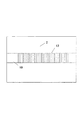
図1を参照すると、本発明にしたがう導波路の概略図が示されている。最初に基板2の表面上にポリマー性バッファ層4が堆積される。基板2は、その上に導波路が固定される任意の材料であってもよく、該材料は、シリコン、シリコン酸化物、ガリウム砒素、シリコン窒化物、ガラス、石英、プラスチック、セラミック、結晶性材料などを含む。基板2は、他の装置、たとえば溝のような形状的特徴または電気回路またはレーザダイオードのような電気光学装置を含んでもよく、含まなくてもよい。
Referring to FIG. 1, a schematic diagram of a waveguide according to the present invention is shown. First, a polymeric buffer layer 4 is deposited on the surface of the
本発明の基板2は、遠距離通信に重要な光学波長において吸収性である可能性があるので、基板2に到達する伝搬光のいずれの部分も吸収にさらされる。基板2による光の吸収は、伝搬する信号からの光強度の望ましくない偏波依存損失をもたらす。中間にあるバッファ層4の目的は、基板2中への光の貫通を制限し、および有意の量の光が基板2に到達することを防止することである。バッファが所望されるように機能するために、その屈折率はコア8の屈折率よりも著しく低いことが必要である。スピンコーティング、ディップコーティング、スロットコーティング、ロールコーティング、ドクターブレーディング、液体キャスティングなどのような、当該技術において知られている多くの異なる方法によって、ポリマー性バッファ層4を付着してもよい。バッファ層4は、アクリレート化合物のような光重合性化合物を含んでもよい。有用なアクリレート化合物は、以下に記載される。光重合性材料の層が基板2の表面上に堆積されたならば、化学線に対する全面露光によって少なくとも部分的に重合される。通常、バッファ層4は約3μmから約500μmまでの厚さを有する。約5μmから約100μmまで、および特に約10μmから約30μmまでの厚さが適当である。
Since the
引き続いて付着されるポリマー層との間の接着を促進し、およびいくつかの場合においては界面における屈折率の傾斜を制御する手段として、モノマーの相互浸透および層の間の共有結合の生成を促進するために、前述のバッファ層4を含む最初に付着される層を、意図的に、相当に硬化不足(under-cured)の状態にすることができる。 Promotes adhesion between subsequently deposited polymer layers and, in some cases, as a means of controlling the refractive index gradient at the interface, promoting monomer interpenetration and the formation of covalent bonds between layers In order to do so, the first applied layer, including the buffer layer 4 described above, can be deliberately under-cured.
バッファ層4を堆積させ部分的に重合させた後に、バッファ層4の表面上にコア8を形成する。1つの実施形態において、コア8は、バッファ層4の表面上に、光透過性でシングルモードの感光性コア層を堆積させることにより形成される。スピンコーティング、ディップコーティング、スロットコーティング、ロールコーティング、ドクターブレーディング、液体キャスティングなどのようなよく知られている方法によって、コアの光重合性組成物の層が堆積される。次に、化学線に対して感光性コア層を画像様に暴露し、そして現像し、それによってコア層の非画像区域を除去し、かつコア層の画像区域を除去しない。そのプロセスは、以下により詳細に記載される。該層を現像した後に、パターニングされ光透過性のコア8がバッファ層4の上に形成され、およびバッファ層4の一部が部分的に露わにされる。この作成段階におけるコア8の構造は、一般的に直立リブと記載される。
After the buffer layer 4 is deposited and partially polymerized, the
本発明の別の実施形態において、コア層8は、バッファ層4の表面上に光透過性でポリマー性のコア層材料のパターンを堆積させることによって形成される。コアのパターンはよく知られているパターン状堆積の付加的方法を用いて製造されてもよいし、反応性イオンエッチングのような他の減少的方法を用いて製造されてもよい。いずれの実施形態においても、コア8の断面幅は、その断面高さとほぼ等しい。通常、コア層8は、それぞれ約2μmから約10μmまでの範囲で変動する断面幅および断面高さを有し、より適当には、コアはそれぞれ約5.5μmから約8μmまでの範囲内で変動する断面幅および断面高さを有する。また、コア8の幅はコアの高さの約2倍以下であり、かつ該高さは該幅の約2倍以下であることが通常である。さらに、通常、コア8は、その幅および高さのそれぞれにおいてシングルモードであり、およびほぼ同一の高さおよび幅を有する。導波路の通常の大きさは、互いに等しくてもよい高さおよび幅を有し、両方ともに約2μm、約4μm、約5μm、約6μm、約7μm、約8μm、約9μm、または約10μmである、コアを含む。また、コア8の幅はコアの高さの約2倍以下であり、かつ該高さは該幅の約2倍以下であることが通常である。標準的シングルモードガラスファイバー(たとえば、Corning Incorporatedにより販売されるSMF-28)に対するカップリング損失を最小限にするために、6×6μmと8×8μmとの間のコア断面の寸法を用いてもよい。コアが、Δnの値とともに、約1300nmより長波長、望ましくは約1520nmより長波長の全ての光通信波長に関して導波路がシングルモードであるように選択される断面幅および断面高さを有することが好ましい。コア層8の材料は、以下に詳細に記載される重合性アクリレート材料を含む。
In another embodiment of the invention, the
コア8が形成される後に、コア8の上部表面上に、コア8の側壁9上に、およびバッファ層4の露わにされた部分の上に、上部クラッド層10が堆積される。また、前述の技術によって光重合性上部クラッド層10を付着させて、そして次に化学線に対して全面暴露してもよい。上部クラッド層10は、印加される光をコア8中に保持することができる任意の材料であることができ、および以下に詳細に記載される重合性アクリレート化合物を含んでもよい。1つの実施形態において、上部クラッド層10は、通常約3から約20μm、より通常には約5から約20μm、より適当には約8から約15μmの、コア8の上面から測定される厚さを有する。
After the
導波路は、光重合性光学材料を用いて形成される。該光重合性光学材料は、それぞれの層において所望される屈折率を提供するためにブレンドされるモノマー成分およびオリゴマー成分の混合物を含む。それぞれの層の具体的な屈折率は、導波路の性能に著しい効果を有する。コア8、バッファ4および上部クラッド10のそれぞれにおいて用いられる光重合性化合物を選択する際には、コア8が屈折率ncを有し、屈折率ncは上部クラッド層の屈折率noより大きく、Δn=nc−noであり、ncとバッファの屈折率nbとの差は、少なくともΔnの約1.5倍であることが重要である。より通常には、ncとnbとの差は、少なくともΔnの約2倍である。最も適当には、ncとnbとの差は、少なくともΔnの約3倍である。本発明の1つの実施形態において、Δnは約0.0031から約0.079までの範囲内で変動する。
The waveguide is formed using a photopolymerizable optical material. The photopolymerizable optical material includes a mixture of monomeric and oligomeric components that are blended to provide the desired refractive index in each layer. The specific refractive index of each layer has a significant effect on the performance of the waveguide.
本発明の通常の実施において、製造される導波性構造はシングルモードである。導波路がシングルモードであることを保証することは、導波路の物理的な断面の大きさおよび形状とΔnの値との特定の関係を維持することを必然的に伴う。一般的に、導波路の寸法を固定値に保持する場合、導波路がシングルモードであるべき場合に越えることができないΔnの最大(カットオフ)値が存在する。同様に、Δnの値を固定値に保持する場合に、導波路がシングルモードであるべき場合に越えることができない導波路の最大断面寸法が存在する。例示として、以下の表は、正方形断面を有する導波路の一般的ケースに関して、大きさとΔnの許容される最大値との関係を表す。最後に、導波路のカップリング効率を最大限とし、屈曲時の光伝搬損失を最小限にするために、一般的に、カットオフ値とほぼ等しいがそれを越えないΔnの値を用いることが望ましい。 In the normal practice of the invention, the waveguide structure produced is single mode. Ensuring that the waveguide is single mode entails maintaining a specific relationship between the physical cross-sectional size and shape of the waveguide and the value of Δn. In general, when keeping the waveguide dimensions at a fixed value, there is a maximum (cutoff) value of Δn that cannot be exceeded if the waveguide should be single mode. Similarly, there is a maximum cross-sectional dimension of the waveguide that cannot be exceeded if the waveguide should be single mode when the value of Δn is held at a fixed value. By way of example, the following table represents the relationship between the magnitude and the maximum allowable value of Δn for the general case of a waveguide having a square cross section. Finally, in order to maximize the coupling efficiency of the waveguide and minimize the light propagation loss during bending, it is common to use a value of Δn that is approximately equal to the cut-off value but does not exceed it. desirable.

コア8の屈折率ncは、一般に約1.33から約1.7まで、またはより通常には約1.4から約1.55までの範囲内である。上部クラッドは、一般に約1.3から約1.65まで、またはより通常には約1.35から約1.55までの範囲内の屈折率noを有する。コア材料および上部クラッド層よりも低い屈折率nbを有するバッファ層4を製造する化合物を選択するように選択することが重要である。バッファ層4は、通常は約1.3から約1.55まで、またはより適当には約1.3から約1.4までの範囲内の屈折率noを有する。これらの屈折率の測定値は、1550nmにおいて測定される。
Refractive index n c of the
これら混合物のフォトリソグラフィーにおいて、コア8のモノマー成分がバッファ層4中に移動することは一般的であり、コア8の床部11とバッファ層4との間に床部界面領域14を形成し、床部界面領域14は屈折率nfを有し、コア8の側壁9と上部クラッド層10との間の側部界面領域12、側部界面領域12は屈折率nsを有する。これらの界面領域12および14は、図1中に見出すことができる。これらの界面領域12および14は、段階的屈折率よりも傾斜屈折率を有する。コア8、上部クラッド10およびバッファ4のモノマーがそれらそれぞれの領域の外へと拡散し、それらの境界において混合できることにより、界面領域12および14が形成される。引き続く化学線に対する暴露の結果として、コアおよび次に上部クラッドが硬化される際に、これらの領域の混合は恒久的に固定される。コア8、上部クラッド10およびバッファ4のモノマーの相互拡散の程度は、その温度におけるバッファ4、上部クラッド10およびコア8の硬化の程度、および用いられるモノマーの拡散性、および最終工程において完全な導波路構造が固く硬化される前の、未硬化層または部分的に硬化された層の間の接触の時間に依存する。コア8の底部および側部においてモノマーの相互拡散が最大である。なぜなら、これらの領域は、中間製作工程の間中、典型的にはそれほど硬化されていないからである。この低い程度の硬化は、コア−バッファ界面の場合には、コア8およびバッファ4の間の結合を促進させる要望によって引き起こされ、コアの側部の場合には、マスクベースのリソグラフィーにおける回折効果によって引き起こされる端部における硬化線量の減少により、またはレーザ直接書込み製作技術においてはビーム断面の強度の変化によってひきおこされる。
In photolithography of these mixtures, it is common for the monomer component of the
図2から分かるように、理想的性能を有する理想的導波路が示されている。理想的には、周囲の理想的上部コア18へのコア成分の拡散がなく、基板2中に光が吸収されることなく、光は理想的コア16を通して送信される。しかしながら、実際には、慣用の従来技術の導波路は、上部クラッド24がコア22の高さに起因する隆起を有する、図3中に示されるものにより近く見える。この隆起は望ましいものではなく、かつ不利である。図4および図5もまた、従来技術の不利な導波路を示す。図4は、下部クラッド28中に形成されている高屈折率の導波領域32を有する導波路を示す。導波領域32は、下部クラッドを貫いて、相当量の光が漏れかつ吸収される恐れがある基板2まで延在している。図5は、導波領域32が基板に到達するのを防止する努力として、下部クラッド28の下に低屈折率のバッファ層34を有する導波路を示す。導波光が依然としてコア26の下にある領域32へと漏れるので、この種の導波路は、導波路におけるモードの形状と慣用のファイバにおけるモードの形状との劣悪な整合により、高いカップリング損失を有する。本発明は従来技術の問題点を減少させ、下部クラッド層を排除することおよび本明細書中に記載される屈折率を有するバッファ層を使用することによって、これらの導波領域によって引き起こされる損失を限界内に留める。
As can be seen from FIG. 2, an ideal waveguide with ideal performance is shown. Ideally, light is transmitted through the
一般的に、側部界面12は、床部界面14の屈折率nfとほぼ等しい屈折率nsを有する。本発明の1つの実施形態において、nsは漸減する屈折率であり、側部界面領域のコアの側壁9に最も近い部分のほぼncから、側部界面領域12の上部クラッド層10に最も近い部分のほぼnoまで減少する。本発明の別の実施形態において、nfは漸減する屈折率であり、床部界面領域14のコア8の床部11に最も近い部分のほぼncから、床部界面領域14のバッファ層4に最も近い部分のほぼnbまで減少する。また、漸減する屈折率nsは、漸減する屈折率nfとほぼ同一、すなわちほぼ調和させることが望ましい。これは、横方向の媒質の単位長さ当たりの屈折率の変化、および同一の開始値および停止値を意味する。
In general, the
バッファ層4,上部クラッド層10およびコア8のそれぞれを形成するのに用いられる組成物は、それぞれ光重合性化合物および光開始剤を含んでもよい。光重合性化合物は、付加重合可能であり、非ガス状(標準大気圧において30℃より高い沸騰温度)であり、少なくとも1つの末端エチレン性不飽和基を含むエチレン性不飽和化合物であり、フリーラジカルによって開始される連鎖成長付加重合によって高分子量のポリマーを形成することができるモノマー、オリゴマーまたはポリマーであってもよい。そのような化合物は当該技術においてよく知られている。それらは、形成される重合された要素が前述のような望ましい屈折率を有するように選択される。具体的に選択される組成物重合物の屈折率の測定は、当業者によって容易に決定される。
The composition used to form each of the buffer layer 4, the
多官能性アクリレートモノマーが適当である。多官能性アクリレートの一般化された構造を以下に示す。 Multifunctional acrylate monomers are suitable. The generalized structure of the multifunctional acrylate is shown below.
コアに関して、mは1から約6までの範囲内で変動してもよく、R2はHまたはCH3であり、およびR1は脂肪族、芳香族または脂肪族と芳香族が混合された有機分子セグメントの連結部である。好適には、R1は、アルキレン、アルキレンオキシド、アリーレンオキシド、脂肪族ポリエーテルまたはポリエステル部分であり、およびR2は好ましくはHである。フィルムの耐溶媒性および高コントラストのリソグラフィーを保証するため、架橋されるポリマー、したがって、多官能性アクリレートモノマー(m≧2)が適当である。また、柔軟で低ガラス転移温度(Tg)のポリマーを用いることにより、最終の導波装置の応力に誘起される散乱光学損失を減少させることが望ましい。架橋されたポリマーのガラス転移温度(Tg)は、架橋密度および架橋点の間の結合部(リンケージ)の構造に依存することが、当該技術において知られている。また、低い架橋密度および柔軟な結合部(リンケージ)の両方が低いTgに必要であることが知られている。低い架橋密度を保証するために、1≦m≦3、理想的にはm=2を有するモノマーおよび2つのエチレン性不飽和官能基の間の長い結合(リンケージ)セグメントが有用である。本発明に関して、長い結合(リンケージ)セグメントとは、少なくとも4炭素原子以上および適当には6以上の平均分子鎖長を有するものである。適当な柔軟な結合(リンケージ)構造は、約3炭素原子より長い鎖長を有するアルキレン類、ポリ(エチレンオキシド)、ポリ(プロピレンオキシド)、エトキシル化されたビスフェノールA、ポリエーテル、チオエーテル、脂肪族および芳香族炭化水素、エーテル、エステル、およびポリシロキサンなどを含む。これらは任意選択的に、重合性化合物の光重合する能力を損なわず、目的の光波長(たとえば、遠距離通信用の1.31および1.51μmの波長)において過度の損失を付加しない側基で置換されていてもよい。適当な置換基は、非制限的に、アルキル、アリール、アルコキシおよびスルホキシド基などを含む。熱分解および変色に対する高い抵抗性を確実にするために、熱的に安定な分子構造のR1が適当である。そのようなR1セグメントは、芳香族ウレタンおよびアミド基のような熱的影響を受けやすい部分を持つべきではない。低い複屈折を保証するために、低い応力光学係数および光学分極率を有するR1結合部(リンケージ)が通常である。 With respect to the core, m may vary within the range of 1 to about 6, R 2 is H or CH 3 , and R 1 is aliphatic, aromatic or an organic mixture of aliphatic and aromatic. It is a connecting part of molecular segments. Suitably R 1 is an alkylene, alkylene oxide, arylene oxide, aliphatic polyether or polyester moiety, and R 2 is preferably H. In order to ensure the solvent resistance of the film and high contrast lithography, polymers which are cross-linked and thus multifunctional acrylate monomers (m ≧ 2) are suitable. It is also desirable to reduce the scattering optical loss induced by stress in the final waveguide device by using a flexible, low glass transition temperature (Tg) polymer. It is known in the art that the glass transition temperature (Tg) of a crosslinked polymer depends on the crosslinking density and the structure of the linkage between the crosslinking points. It is also known that both low crosslink density and flexible linkages are required for low Tg. To ensure low crosslink density, a long linkage segment between a monomer having 1 ≦ m ≦ 3, ideally m = 2, and two ethylenically unsaturated functional groups is useful. In the context of the present invention, long linkage segments are those having an average molecular chain length of at least 4 carbon atoms and suitably 6 or more. Suitable flexible linkage structures include alkylenes having chain lengths greater than about 3 carbon atoms, poly (ethylene oxide), poly (propylene oxide), ethoxylated bisphenol A, polyethers, thioethers, aliphatics and Includes aromatic hydrocarbons, ethers, esters, polysiloxanes, and the like. These are optionally side groups that do not impair the ability of the polymerizable compound to photopolymerize and do not add undue loss at the desired light wavelengths (eg, 1.31 and 1.51 μm wavelengths for telecommunications). May be substituted. Suitable substituents include, but are not limited to, alkyl, aryl, alkoxy and sulfoxide groups. In order to ensure a high resistance to thermal decomposition and discoloration, a thermally stable molecular structure R 1 is suitable. Such R 1 segments should not have thermally sensitive moieties such as aromatic urethane and amide groups. In order to ensure low birefringence, R 1 bonds (linkages) with low stress optical coefficients and optical polarizabilities are common.
上部クラッド層に関して、アクリレートは前述と同様であるが、エチレン性不飽和官能基の間の平均分子鎖長は、約6炭素原子以上、通常8以上、およびより適当には12以上であってもよい。適当な柔軟性結合部(リンケージ)構造は、6炭素原子より長い鎖長を有するアルキレン、ポリ(エチレンオキシド)、ポリ(プロピレンオキシド)およびエトキシル化されたビスフェノールAを含む。 For the upper cladding layer, the acrylate is as described above, but the average molecular chain length between the ethylenically unsaturated functional groups may be about 6 carbon atoms or more, usually 8 or more, and more suitably 12 or more. Good. Suitable flexible linkage structures include alkylene, poly (ethylene oxide), poly (propylene oxide) and ethoxylated bisphenol A having chain lengths greater than 6 carbon atoms.
本発明の実施形態において、バッファ4,コア層8および上部クラッド層10のそれぞれの材料は、同様に、アクリル酸の重合性エステルおよび部分エステル、および2〜30炭素原子を含む芳香族および脂肪族ポリオールの重合性エステルおよび部分エステルを含む。同様に、ポリアルキレングリコール類の部分エステルおよびエステルも適当である。例は、エチレングリコールジアクリレート、ジエチレングリコールジアクリレート、トリエチレングリコールジアクリレート、テトラエチレングリコールジアクリレート、200から2000までの範囲内の平均分子量を有するポリエチレングリコールジアクリレート類およびポリプロピレングリコールジアクリレート類、プロピレングリコールジアクリレート、ジプロピレングリコールジアクリレート、ヘキサンジオールジアクリレートおよびブタンジオールジアクリレートのような(C2〜C40)アルカンジオールジアクリレート類、トリプロピレングリコールジアクリレート、トリメチロールプロパントリアクリレート、500〜1500までの範囲内の平均分子量を有するエトキシル化されたトリメチロールプロパントリアクリレート類、ペンタエリスリトールジアクリレート、ペンタエリスリトールトリアクリレート、ペンタエリスリトールテトラアクリレート、ジペンタエリスリトールジアクリレート、ジペンタエリスリトールトリアクリレート、ジペンタエリスリトールテトラアクリレート、ジペンタエリスリトールペンタアクリレート、ジペンタエリスリトールヘキサアクリレート、トリペンタエリスリトールオクタアクリレート、ソルビトールトリアクリレート、ソルビトールテトラアクリレート、ソルビトールペンタアクリレート、ソルビトールヘキサアクリレート、オリゴエステルアクリレート類、グリセロールジ−およびトリアクリレート、1,4−シクロヘキサンジアクリレート、100〜1500までの平均分子量を有するポリエチレングリコールのビスアクリレート類、および前述の化合物の混合物である。多官能性アクリレートオリゴマーは、アクリル化されたエポキシ、アクリル化されたポリウレタンおよびアクリル化されたポリエステルを含むが、それらに限定されるものではない。光重合性化合物はアリールアクリレートを含む。そのようなアリールアクリレートモノマーの例示は、アリールジアクリレート、トリアクリレートおよびテトラアクリレートを含み、たとえば、ベンゼン、ナフタレン、ビスフェノールA、ビフェニレン、メタンビフェニレン、トリフルオロメタンビフェニレン、フェノキシフェニレンなどをベースとするジアクリレート類、トリアクリレート類およびテトラアクリレート類である。アリールアクリレートモノマーは、多官能性アリールアクリレートであってもよく、より通常にはアリールアクリレートモノマーは、ビスフェノール−Aの構造をベースとするジアクリレート類、トリアクリレート類およびテトラアクリレート類である。通常のアリールアクリレートモノマーは、エトキシル化されたビスフェノール−Aジアクリレート、プロポキシル化されたビスフェノール−Aジアクリレートおよびエトキシル化されたヘキサフルオロビスフェノール−Aジアクリレートのようなアルコキシル化されたビスフェノール−Aジアクリレートである。選択されるアリールアクリレートモノマーは、エトキシル化されたビスフェノール−Aジアクリレートである。望ましい重合性成分は、構造(I)を有するモノマーである。
In embodiments of the present invention, the respective materials of the buffer 4, the
1つの実施形態において、コアに関してnは約10以下であり、通常約4以下であり、およびより適当には約2以下である。1つの実施形態において、クラッド層に関して、nは約2以上であり、通常約4以上であり、およびより適当には約10以上である。同様に有用なものは、当該技術においてよく知られているアクリレート含有コポリマーである。実施形態において、クラッド層は、前述のエトキシル化されたビスフェノール−Aジアクリレート構造(I)(式中、1≦n≦20、通常4≦n≦15、およびより適当には8≦n≦12)を有する重合性成分を含む。 In one embodiment, n for the core is about 10 or less, usually about 4 or less, and more suitably about 2 or less. In one embodiment, for the cladding layer, n is about 2 or greater, usually about 4 or greater, and more suitably about 10 or greater. Also useful are acrylate-containing copolymers that are well known in the art. In embodiments, the cladding layer comprises the ethoxylated bisphenol-A diacrylate structure (I) described above, wherein 1 ≦ n ≦ 20, usually 4 ≦ n ≦ 15, and more suitably 8 ≦ n ≦ 12. ) Containing a polymerizable component.
重合性組成物は、多官能性フッ素化(メタ)アクリレート類、特に、以下の構造に基づくものであってもよい。 The polymerizable composition may be based on polyfunctional fluorinated (meth) acrylates, particularly those having the following structure.
(式中、YはHまたはDであり;XはH、D、F、ClまたはCH3であり、およびnは2から4までの整数であり、 Wherein Y is H or D; X is H, D, F, Cl or CH 3 , and n is an integer from 2 to 4;
(式中k、m、nおよびpは整数である))。 (Where k, m, n and p are integers).
これらの材料は、1550nmにおいて0.17dB/cmほどの少なさの伝搬損失を有する導波路を製造する。これらの材料のガラス転移温度(Tg)は、熱光学装置の動作温度以下であるように簡単に選択できる。これらの材料の低Tgバージョンは、回折格子に補助される測定において無視できる複屈折を有すること、および大きな屈折率の温度微分値を有することが示されており、それはパワー効率の高い熱光学装置(光学スイッチおよびチューナブル回折格子のようなもの)の製作を可能にする。有用なフッ素化(メタ)アクリレート類は、たとえば、以下に示される反応により、Ausimont S.p.A (Milan, ITALY)から商業的に入手可能な、ポリオールFluorolink(登録商標)Tから作製されるテトラアクリレートF60TAを含む。 These materials produce waveguides with propagation losses as low as 0.17 dB / cm at 1550 nm. The glass transition temperature (Tg) of these materials can be easily selected so as to be lower than the operating temperature of the thermo-optical device. Low Tg versions of these materials have been shown to have negligible birefringence in diffraction assisted measurements and to have a large refractive index temperature derivative, which is a power efficient thermo-optic device (Such as optical switches and tunable diffraction gratings) can be made. Useful fluorinated (meth) acrylates include tetraacrylate F60TA made from polyol Fluorolink® T, commercially available from Ausimont SpA (Milan, ITALY), for example, by the reaction shown below. Including.
他の多官能アクリレート類は、Akzo Chemicals B.V. (Amersfoort, Netherlands)製のC6DIACRY:
CH2=CHCO2CH2(CF2)4CH2O2CCH=CH2
3M Company (Saint Paul, Minnesota)製のL-12043:
CH2=CHCO2CH2CF(CF3)O(CF2)4O[CF(CF3)CF2O]pCF(CF3)CH2O2CCH=CH2
3M Company製のL-9367:
CH2=CHCO2CH2(CF2CF2O)m(CF2O)nCF2CH2O2CCH=CH2
を含む。
Other polyfunctional acrylates are C6DIACRY from Akzo Chemicals BV (Amersfoort, Netherlands):
CH 2 = CHCO 2 CH 2 (CF 2 ) 4 CH 2 O 2 CCH = CH 2
L-12043 from 3M Company (Saint Paul, Minnesota):
CH 2 = CHCO 2 CH 2 CF (CF 3 ) O (CF 2 ) 4 O [CF (CF 3 ) CF 2 O] p CF (CF 3 ) CH 2 O 2 CCH = CH 2
L-9367 from 3M Company:
CH 2 = CHCO 2 CH 2 (CF 2 CF 2 O) m (CF 2 O) n CF 2 CH 2 O 2 CCH = CH 2
including.
バッファ、上部クラッドおよびコアのそれぞれが構造的に類似の組成物で構成されていてもよいが、バッファおよび上部クラッドのそれぞれがコアの屈折率よりも低い屈折率を有するために、それらは、個々の用途に関して異なる化学組成を有さなければならない。たとえば、バッファ層の組成物はクラッド層と類似のTg特性を有してもよいが、同一の組成である必要はない。光重合性材料および加工条件は、重合されたバッファのTgが約60℃以下、通常約40℃以下およびより適当には約25℃以下からの範囲で変動するように選択される。 Each of the buffer, upper cladding and core may be composed of a structurally similar composition, but because each of the buffer and upper cladding has a refractive index lower than that of the core, they are individually Must have different chemical compositions for different applications. For example, the composition of the buffer layer may have a Tg characteristic similar to that of the cladding layer, but need not be the same composition. The photopolymerizable material and processing conditions are selected such that the Tg of the polymerized buffer varies from about 60 ° C. or less, usually from about 40 ° C. or less, and more suitably from about 25 ° C. or less.
光導波路コアに用いられる光重合性化合物が、重合の後に約80℃以下および適当には約50℃以下のガラス転移温度を有するコアを製造することが本発明の特徴である。導波路クラッド層に用いられる光重合性化合物が、重合の後に約60℃以下、通常約40℃以下およびより適当には約25℃以下のガラス転移温度を有するクラッド層を製造することが本発明の特徴である。重合性成分の特徴付けおよび選択により、当業者は、特定のTgを容易に得ることができる。これは、重合性成分の分子量、不飽和部位の数および架橋密度のような要因に依存する。単一の重合された成分がそれ自身として要求されるTgを有するか、あるいは所望されるTgを有する重合性モノマー、オリゴマーおよび/またはポリマーをブレンドすることにより重合性成分を調整してもよい。また、重合が実施される際の暴露時間および温度を変化させることによってTgを制御してもよい。 It is a feature of the present invention that the photopolymerizable compound used in the optical waveguide core produces a core having a glass transition temperature of about 80 ° C. or less and suitably about 50 ° C. or less after polymerization. It is the present invention that the photopolymerizable compound used in the waveguide cladding layer produces a cladding layer having a glass transition temperature of about 60 ° C. or less, usually about 40 ° C. or less and more suitably about 25 ° C. or less after polymerization. It is the feature. By characterization and selection of the polymerizable component, one skilled in the art can readily obtain a particular Tg. This depends on factors such as the molecular weight of the polymerizable component, the number of unsaturated sites and the crosslink density. The polymerizable component may be tuned by blending polymerizable monomers, oligomers and / or polymers where the single polymerized component has the required Tg as such or has the desired Tg. Alternatively, the Tg may be controlled by changing the exposure time and temperature when the polymerization is carried out.
それぞれの光重合性組成物全体中に、充分な化学線に対する暴露時に光重合するのに充分な量において、光重合性化合物が存在する。組成物中の光重合性化合物の量は広範に変化し得るが、光透過性装置の光透過性要素としての使用のためのフォトポリマーの調製における使用のための光重合性組成物に通常用いられる量を用いてもよい。光重合性化合物の量は、一般的に組成物の約35質量%から約99.9質量%までの量において用いられる。光重合性化合物は、全組成物の重量に基づいて、通常約80質量%から約99.5質量%まで、およびより適当には約95〜99%の量において、全組成物中に存在する。 In each entire photopolymerizable composition, the photopolymerizable compound is present in an amount sufficient to photopolymerize upon exposure to sufficient actinic radiation. The amount of photopolymerizable compound in the composition can vary widely, but is typically used in photopolymerizable compositions for use in the preparation of photopolymers for use as light transmissive elements in light transmissive devices. The amount to be used may be used. The amount of photopolymerizable compound is generally used in an amount from about 35% to about 99.9% by weight of the composition. The photopolymerizable compound is present in the total composition, usually in an amount of about 80% to about 99.5%, and more suitably about 95-99%, based on the weight of the total composition. .
それぞれの感光性組成物は、光分解的にフリーラジカルを生成する少なくとも1つのフリーラジカル生成光開始剤をさらに含む。通常、光開始剤は、化学線によって活性化されるフリーラジカル生成付加重合開始剤であり、室温付近(たとえば約20℃から約80℃まで)では熱的に不活性である。アクリレートを光重合することが知られている任意の光開始剤を用いることができる。光開始剤は、当該技術において知られているキノキサリン化合物、ビシナルポリケトアルドニル化合物、α−カルボニル類;アシロインエーテル類;トリアリールイミダゾール二量体類;α−炭化水素置換芳香族アシロイン類;多核キノン類およびs−トリアジン類を非排他的に含む。 Each photosensitive composition further includes at least one free radical generating photoinitiator that photolytically generates free radicals. Typically, the photoinitiator is a free radical-generating addition polymerization initiator that is activated by actinic radiation and is thermally inactive near room temperature (eg, from about 20 ° C. to about 80 ° C.). Any photoinitiator known to photopolymerize acrylates can be used. Photoinitiators are quinoxaline compounds, vicinal polyketoaldonyl compounds, α-carbonyls; acyloin ethers; triarylimidazole dimers; α-hydrocarbon substituted aromatic acyloins known in the art. Non-exclusively including polynuclear quinones and s-triazines.
適当な光開始剤は、ベンゾフェノン、アクリル化されたベンゾフェノン、2−エチルアントラキノン、フェナントラキノン、2−tert−ブチルアントラキノン、1,2−ベンゾアントラキノン、2,3−ベンゾアントラキノン、2,3−ジクロロナフトキノン、ベンジルジメチルケタールのような芳香族ケトン類、および他の芳香族ケトン類(たとえば、ベンゾイン、ベンゾインメチルエーテル、ベンゾインエチルエーテル、ベンゾインイソブチルエーテルおよびベンゾインフェニルエーテルのようなベンゾインエーテル類、メチルベンゾイン、エチルベンゾイン、および他のベンゾイン類)を含む。光開始剤は、1−ヒドロキシシクロヘキシルフェニルケトン(Irgacure(登録商標)184)、ベンゾイン、ベンゾインエチルエーテル、ベンゾインイソプロピルエーテル、ベンゾフェノン、ベンゾジメチルケタール(Irgacure 651)、2,2−ジエチルオキシアセトフェノン、E. Merck (Darmstadt, Germany)製の2−ヒドロキシ−2−メチル−1−フェニルプロパン−1−オン(Darocur(登録商標)1173);1−[4−(2−ヒドロキシエトキシ)フェニル]−2−ヒドロキシ−2−メチルプロパン−1−オン(Darocur(登録商標)2959)、2−メチル−1−[(4−メチルチオ)フェニル]−2−モルホリノプロパン−1−オン(Irgacure(登録商標)907)、2−ベンジル−2−ジメチルアミノ−1−(4−モルホリノフェニル)−ブタン−1−オン(Irgacure(登録商標)369)、ポリ{1−[4−(1−メチルビニル)フェニル]−2−ヒドロキシ−2−メチル−プロパン−1−オン}(Esacure KIP)、Great Lake Fine Chemicals Limited (London, England)製の[4−(4−メチルフェニルチオ)フェニル]フェニルメタノン(Quantacure(登録商標)BMS)およびジ−カンファーキノンを含む。最も適当な光開始剤は、照射時に黄色化する傾向を持たないものである。そのような光開始剤は、ベンゾジメチルケタール(Irgacure(登録商標)651)、2−ヒドロキシ−2−メチル−1−フェニルプロパン−1−オン(Darocur(登録商標)1173)、1−ヒドロキシシクロヘキシルフェニルケトン(Irgacure(登録商標)184)、および1−[4−(2−ヒドロキシエトキシ)フェニル]−2−ヒドロキシ−2−メチルプロパン−1−オン(Darocur(登録商標)2959)を含む。Fluorolink(登録商標)-TおよびC6DIACRYLは混和性であり、UV硬化のために慣用の光開始剤を用いることができる。材料L-12043およびL-9367のようなより高度にフッ素化された多官能性アクリレートに関しては、フッ素化された光開始剤を使用してもよい。 Suitable photoinitiators are benzophenone, acrylated benzophenone, 2-ethylanthraquinone, phenanthraquinone, 2-tert-butylanthraquinone, 1,2-benzoanthraquinone, 2,3-benzoanthraquinone, 2,3- Aromatic ketones such as dichloronaphthoquinone, benzyldimethyl ketal, and other aromatic ketones (eg, benzoin ethers such as benzoin, benzoin methyl ether, benzoin ethyl ether, benzoin isobutyl ether and benzoin phenyl ether, methyl benzoin) , Ethyl benzoin, and other benzoins). Photoinitiators include 1-hydroxycyclohexyl phenyl ketone (Irgacure® 184), benzoin, benzoin ethyl ether, benzoin isopropyl ether, benzophenone, benzodimethyl ketal (Irgacure 651), 2,2-diethyloxyacetophenone, E.I. 2-hydroxy-2-methyl-1-phenylpropan-1-one (Darocur® 1173) from Merck (Darmstadt, Germany); 1- [4- (2-hydroxyethoxy) phenyl] -2-hydroxy 2-methylpropan-1-one (Darocur® 2959), 2-methyl-1-[(4-methylthio) phenyl] -2-morpholinopropan-1-one (Irgacure® 907), 2-Benzyl-2-dimethylamino-1- (4-morpholinophenyl) -butan-1-one (Irgacure (registered trader) 369), poly {1- [4- (1-methylvinyl) phenyl] -2-hydroxy-2-methyl-propan-1-one} (Esacure KIP), manufactured by Great Lake Fine Chemicals Limited (London, England) [4- (4-methylphenylthio) phenyl] phenylmethanone (Quantacure® BMS) and di-camphorquinone. Most suitable photoinitiators are those that do not tend to yellow upon irradiation. Such photoinitiators include benzodimethyl ketal (Irgacure® 651), 2-hydroxy-2-methyl-1-phenylpropan-1-one (Darocur® 1173), 1-hydroxycyclohexyl phenyl. Ketones (Irgacure® 184), and 1- [4- (2-hydroxyethoxy) phenyl] -2-hydroxy-2-methylpropan-1-one (Darocur® 2959). Fluorolink®-T and C6DIACRYL are miscible and conventional photoinitiators can be used for UV curing. For more highly fluorinated multifunctional acrylates such as materials L-12043 and L-9367, a fluorinated photoinitiator may be used.
それぞれの光重合性組成物中に、フリーラジカルを生成する光開始剤は、充分な化学線に対する暴露時に光重合性化合物の光重合を実施できるのに充分な量で存在する。光開始剤は、通常総組成物の約0.01質量%から約10質量%までの量で、またはより通常には0.1%から6%までの量で、およびより適当には組成物の総重量に基づいて約0.5質量%から約4質量%までの量で存在する。 In each photopolymerizable composition, the photoinitiator that generates free radicals is present in an amount sufficient to allow photopolymerization of the photopolymerizable compound upon exposure to sufficient actinic radiation. The photoinitiator is usually in an amount of about 0.01% to about 10% by weight of the total composition, or more usually in an amount of 0.1% to 6%, and more suitably the composition Present in an amount from about 0.5% to about 4% by weight, based on the total weight of
また、感光性組成物の目的および最終用途に依存して、感光性組成物に対して他の添加剤を添加してもよい。これらの例は、溶媒、酸化防止剤、光安定剤、体積増量剤、シリカ、チタニア、ガラス球などのような充填剤(特に、ナノスケールの状況においては、すなわち約100nm未満の粒度を有する)、染料、フリーラジカル捕捉剤、コントラスト向上剤、ニトロン類およびUV吸収剤を含む。酸化防止剤は、Ciba-Geigy corporation Corporation (Tarrytown New York)製のIrganox(登録商標)1010を含むフェノール類および特にヒンダードフェノール類;スルフィド類;有機ホウ素化合物;有機リン化合物;Ciba-GeigyからIrganox(登録商標)1098の商標の下で入手可能なN,N’−ヘキサメチレンビス(3,5−ジ−tert−ブチル−4−ヒドロキシヒドロシンナムアミド)のような化合物を含む。光安定剤およびより詳細にはヒンダードアミン光安定剤は、Cytec Industries (Wilmington, Delaware)から商標「Cyasorb(登録商標)UV-3346」の下で入手可能な、ポリ[(6−モルホリノ−s−トリアジン−2,4−ジイル)[(2,2,6,6−テトラメチル−4−ピペリジル)イミノ]−ヘキサメチレン[(2,2,6,6−テトラメチル−4−ピペリジル)イミノ]を含むが、それに限定されるものではない。体積膨張化合物は、Beiley'sモノマーとして知られるらせん状モノマー類のような材料を含む。染料の例は、メチレングリーン、メチレンブルーなどを含む。適当なフリーラジカル捕捉剤は、酸素、ヒンダードアミン光安定剤、ヒンダードフェノール類、2,2,6,6−テトラメチル−1−ピペリジニルオキシフリーラジカル(TEMPO)などを含む。適当なコントラスト向上剤は、ニトロン類のような他のフリーラジカル捕捉剤を含む。UV吸収剤は、ベンゾトリアゾール、ヒドロキシベンゾフェノンなどを含む。これらの添加剤は、組成物の総重量に基づいて、約0%から約6%まで、および通常は約0.1%から約1%までの量で含有される。全組成物の全ての成分は、互いに混合状態にあり、および最も適当には実質的に均一な混合状態にある。 Further, depending on the purpose and end use of the photosensitive composition, other additives may be added to the photosensitive composition. Examples of these are fillers such as solvents, antioxidants, light stabilizers, volume extenders, silica, titania, glass spheres, etc. (especially in the nanoscale context, ie having a particle size of less than about 100 nm) , Dyes, free radical scavengers, contrast enhancers, nitrones and UV absorbers. Antioxidants include phenols and especially hindered phenols including Irganox® 1010 from Ciba-Geigy Corporation Corporation (Tarrytown New York); sulfides; organoboron compounds; organophosphorus compounds; Irganox from Ciba-Geigy And compounds such as N, N′-hexamethylenebis (3,5-di-tert-butyl-4-hydroxyhydrocinnamamide) available under the trademark 1098. Light stabilizers and more particularly hindered amine light stabilizers are poly [(6-morpholino-s-triazines) available from Cytec Industries (Wilmington, Delaware) under the trademark “Cyasorb® UV-3346”. -2,4-diyl) [(2,2,6,6-tetramethyl-4-piperidyl) imino] -hexamethylene [(2,2,6,6-tetramethyl-4-piperidyl) imino]. However, it is not limited to this. Volume expansion compounds include materials such as helical monomers known as Beiley's monomers. Examples of dyes include methylene green, methylene blue, and the like. Suitable free radical scavengers include oxygen, hindered amine light stabilizers, hindered phenols, 2,2,6,6-tetramethyl-1-piperidinyloxy free radical (TEMPO), and the like. Suitable contrast enhancing agents include other free radical scavengers such as nitrones. UV absorbers include benzotriazole, hydroxybenzophenone, and the like. These additives are included in amounts from about 0% to about 6%, and usually from about 0.1% to about 1%, based on the total weight of the composition. All components of the entire composition are in a mixed state with each other and most suitably in a substantially uniform mixed state.
バッファ層4の上にコア感光性材料が薄膜または厚膜として形成されたならば、コア層の輪郭を描くために、膜に対し化学線を導く。すなわち、コアの位置および寸法を、コア層の表面上の化学線のパターンによって決定する。線のパターンは、所望されるパターンにおいて光重合性組成物を重合させるように、および膜の他の領域を未反応のままにするように選択されなければならない。本発明のフォトポリマーは、光重合性組成物を必要な波長および強度を有する化学線に必要な持続時間にわたって暴露することによって、慣用的に調製される。本明細書において用いられる際に、「化学線」は、電子ビーム、イオンまたは中性子ビームまたはX線に加えて、スペクトルの可視、紫外または赤外領域の光であると定義される。化学線は、非コヒーレント光の形態であってもよいし、レーザからの光のようにコヒーレント光の形態であってもよい。化学線の源、および暴露手順、時間、波長および強度は、所望される重合度、フォトポリマーの屈折率および当業者に知られる他の要因に依存して広範に変化し得る。そのような慣用的な光重合プロセスおよびそれらの動作パラメータは当該技術においてよく知られている。 If the core photosensitive material is formed as a thin or thick film on the buffer layer 4, actinic radiation is directed to the film to delineate the core layer. That is, the position and dimensions of the core are determined by the pattern of actinic radiation on the surface of the core layer. The line pattern must be selected to polymerize the photopolymerizable composition in the desired pattern and to leave other areas of the film unreacted. The photopolymers of the present invention are conventionally prepared by exposing the photopolymerizable composition to actinic radiation having the required wavelength and intensity for the required duration. As used herein, “actinic radiation” is defined as light in the visible, ultraviolet or infrared region of the spectrum, in addition to electron beams, ions or neutron beams or X-rays. The actinic radiation may be in the form of non-coherent light or in the form of coherent light, such as light from a laser. The source of actinic radiation and the exposure procedure, time, wavelength and intensity can vary widely depending on the degree of polymerization desired, the refractive index of the photopolymer and other factors known to those skilled in the art. Such conventional photopolymerization processes and their operating parameters are well known in the art.
化学線源および該化学線の波長は広範に変化してもよく、および任意の慣用の波長および源を使用することができる。1つの実施形態において、比較的短い波長(すなわち高エネルギー)の放射線を用いて光化学的励起を実施して、加工の前に通常遭遇する放射(たとえば、室内光)に対する暴露が光重合性材料を時期尚早に重合させないようにする。したがって、紫外光(300〜400nmの波長)に対する暴露が便利である。同様に、深紫外光(190〜300nmの波長)による暴露が有用である。慣用の源は、加工のための所望の波長を選択するのに適切な光学フィルターを取り付けられた水銀−キセノンアーク灯である。同様に、本発明の実施に関して、短波長のコヒーレント放射線が有用である。350nm付近のいくつかの波長においてUVモードで動作するアルゴンイオンレーザが望ましい。また、257nm付近の出力を有する周波数を2倍化したアルゴンイオンレーザが高度に望ましい。あるいはまた、加工は、レーザのような化学線の高出力源により開始される多フォトンプロセスを用いることもできる。また、電子ビーム硬化の使用により、光開始剤を用いることなしに前述のフッ素化されたモノマーを硬化させることもできる。電子ビーム励起またはイオンビーム励起を用いてもよい。暴露時間は、通常、数秒から約10分まで変化する。温度は、通常、約10℃から約60℃までの範囲内で変動する。しかし、室温がより適当である。加えて、ペルオキシドまたは他の熱開始剤の使用により、これらの材料を熱的に硬化させることもできる。 The source of actinic radiation and the wavelength of the actinic radiation can vary widely, and any conventional wavelength and source can be used. In one embodiment, photochemical excitation is performed using relatively short wavelength (ie, high energy) radiation so that exposure to radiation normally encountered prior to processing (eg, room light) causes the photopolymerizable material to Avoid premature polymerization. Therefore, exposure to ultraviolet light (300-400 nm wavelength) is convenient. Similarly, exposure by deep ultraviolet light (190-300 nm wavelength) is useful. A conventional source is a mercury-xenon arc lamp fitted with an appropriate optical filter to select the desired wavelength for processing. Similarly, short wavelength coherent radiation is useful for the practice of the present invention. An argon ion laser operating in the UV mode at several wavelengths near 350 nm is desirable. An argon ion laser that doubles the frequency having an output near 257 nm is highly desirable. Alternatively, processing can use a multi-photon process initiated by a high power source of actinic radiation such as a laser. The use of electron beam curing can also cure the aforementioned fluorinated monomers without using a photoinitiator. Electron beam excitation or ion beam excitation may be used. The exposure time usually varies from a few seconds to about 10 minutes. The temperature typically varies within a range from about 10 ° C to about 60 ° C. However, room temperature is more appropriate. In addition, these materials can be thermally cured by the use of peroxides or other thermal initiators.
化学線の空間的輪郭(すなわち、光重合性材料の層のどこにあたるか)の制御は、慣用の方法によって実現することができる。たとえば、1つの慣用的方法において、所望されるコアパターンを担持するマスクが、化学線源と光重合性組成物の膜との間に配置される。マスクは、透明領域および不透明領域を有し、膜表面の所望される領域のみに放射線があたることを可能にする。薄膜のマスクを用いる暴露は当該技術においてよく知られており、膜にコアパターンを印刷するための接触技術、近接技術および投影技術を含んでもよい。空間的制御の別の慣用の方法は、レーザまたは電子ビームの指向性ビームまたは合焦されたビームを含む化学線源を使用することである。そのようなビームは、光重合性材料の膜表面の小さい区域のみと交差する。所望されるコアのパターンは、空間中でビームを走査するか、あるいは交差点が静止しているビームに対して相対的に変化するように基板を移動させることにより、この小さい交差点を膜表面を巡って移動させることにより実現される。ビーム源を用いるこれらの種類の暴露は、直接書込み方法として当該技術において知られている。導波路コアの正確な断面形状およびコアの側部に形成される傾斜した屈折率の領域の幅および程度は、直接書込み製作法およびマスク暴露製作法の両方において、光源のコリメーションの程度に影響される。所望される結果に依存して、コリメーションの程度は広範に変化し得る。一般的に、導波路コア構造の精細度のために比較的高度にコリメートされた源を使用することが適当である。10度未満の角度以内のコリメーションが有用である。 Control of the spatial profile of actinic radiation (i.e. where in the layer of photopolymerizable material) can be achieved by conventional methods. For example, in one conventional method, a mask carrying the desired core pattern is placed between the source of actinic radiation and the film of photopolymerizable composition. The mask has transparent and opaque areas and allows radiation to be applied only to the desired areas of the film surface. Exposure using thin film masks is well known in the art and may include contact techniques, proximity techniques and projection techniques for printing a core pattern on the film. Another conventional method of spatial control is to use an actinic radiation source that includes a directional or focused beam of a laser or electron beam. Such a beam intersects only a small area of the film surface of the photopolymerizable material. The desired core pattern can be achieved by scanning the beam in space, or moving the substrate so that the intersection changes relative to the stationary beam, and traversing this small intersection around the film surface. This is realized by moving the These types of exposure using a beam source are known in the art as direct writing methods. The exact cross-sectional shape of the waveguide core and the width and extent of the tilted index region formed on the side of the core are affected by the degree of collimation of the light source in both direct write and mask exposure fabrication methods. The Depending on the desired result, the degree of collimation can vary widely. In general, it is appropriate to use a relatively highly collimated source for the definition of the waveguide core structure. Collimation within an angle of less than 10 degrees is useful.
コア層の光重合性組成物を重合させてコア層の予め決定されたパターンを形成した後に、次にパターンを現像して非画像区域を除去し、予め決定されたパターンを残す。たとえば照射されてない組成物を溶媒で洗い流すことのような、任意の慣用の現像方法を用いることができる。そのような溶媒は、アルコールおよびケトンのような極性溶媒を含む。有用な溶媒は、アセトン、メタノール、プロパノール、テトラヒドロフランおよび酢酸エチルを含み、および高度にフッ素化されたモノマーに関しては、Ausimontから商標「Galden(登録商標)」の下で販売されるもののようなフルオロエーテル溶媒が適当である。 After polymerizing the photopolymerizable composition of the core layer to form a predetermined pattern of the core layer, the pattern is then developed to remove non-image areas and leave the predetermined pattern. Any conventional development method can be used, such as, for example, washing away the unirradiated composition with a solvent. Such solvents include polar solvents such as alcohols and ketones. Useful solvents include acetone, methanol, propanol, tetrahydrofuran and ethyl acetate, and for highly fluorinated monomers, fluoroethers such as those sold under the trademark “Galden®” by Ausimont A solvent is suitable.
バッファおよびクラッド層は完全に硬化させる必要はなく、部分的に重合させる必要があるのみである。部分的に重合させるとは重合後にいくらかのアクリレート基が存在すること、すなわち全てのアクリレートが飽和炭化水素に変換されるのではないことを意味する。これはアクリレート基の数の0%超、通常約10%超、および最も適当には約25%超のアクリレート基が未反応のままであることを意味する。未反応基の数の上限は、モノマーのゲル化点に依存し、それは同様に官能性(モノマー当たりのアクリレート基の数)に依存する。官能性が整数fに等しい場合、未反応基の上限はゲル化を起こすのに充分であり、かつ近似的には(1−1/f)×100%なる関係によって与えられる。例示として、テトラアクリレートモノマーに関して残存する未反応基の数は75%未満であり、およびジアクリレートモノマーに関する残存する未反応基の数は50%未満である。次に続く層の付着に先立つ層の部分的重合は、それらの界面においてそれら層が混合するのを許す。この混合は、それら層間の接着力を向上させ、いくつかの場合において界面における屈折率の傾斜を制御するのに用いることができる。 The buffer and cladding layers need not be fully cured, but only need to be partially polymerized. Partial polymerization means that some acrylate groups are present after polymerization, i.e. not all acrylates are converted to saturated hydrocarbons. This means that more than 0% of the number of acrylate groups, usually more than about 10%, and most suitably more than about 25% acrylate groups remain unreacted. The upper limit on the number of unreacted groups depends on the gel point of the monomer, which in turn depends on the functionality (number of acrylate groups per monomer). When the functionality is equal to the integer f, the upper limit of unreacted groups is sufficient to cause gelation and is approximately given by the relationship (1-1 / f) × 100%. Illustratively, the number of unreacted groups remaining for the tetraacrylate monomer is less than 75%, and the number of remaining unreacted groups for the diacrylate monomer is less than 50%. Partial polymerization of the layers prior to subsequent deposition of the layers allows the layers to mix at their interfaces. This mixing improves the adhesion between the layers and in some cases can be used to control the refractive index gradient at the interface.
それぞれの層が付着され、およい任意選択的にパターニングされるかまたは表面または体積回折格子などを刻み込まれた後に、残存する未重合アクリレートを、それらが実質的に完全に重合するように、化学線に対するブランケット暴露すなわち全体的な暴露によるハードキュアリングにかけられる。回折格子13を図7に示す。最終硬化工程のための硬化線量(表面の単位正方形当たりの全放射線エネルギー)は典型的には、先行する製作工程中にそれぞれの層を部分的に硬化させるのに用いた線量の約10倍から約500倍までである。最も適当には、最終硬化線量は、この中間の線量の約100倍である。この方法において、層は早期の製作工程中にそれらの界面において混合され、そして所望される比率において混合されて、層および全装置の屈折率を精密に調製し、および共有結合により層間の良好な接着を保証することができる。最終的に、所望される構造は最終硬化工程において固定され、さらなる構造の進化が起こらないようにされる。平面状ポリマー光導波路を作成するためには、種々のコアおよびクラッド層の屈折率を精密に制御する必要がある。これは、個々の塗布層に用いられるモノマーの構造を適応させて所望の屈折率を実現することによって、実現することができる。実際には、異なる屈折率を有するいくつかの混和性モノマーを混合して、必要とされる所望の屈折率を得ることがより簡単である。また、強度に反射性の回折格子が必要とされる場合、コア中および任意選択的にクラッド中において2つ以上のモノマーを用いることが適当である。
After each layer is deposited and optionally patterned or engraved with a surface or volume grating, etc., the remaining unpolymerized acrylates are chemically treated so that they polymerize substantially completely. It is subjected to hard curing by blanket exposure to the wire, ie overall exposure. The
提示したリソグラフィー的方法を用いて平面状導波路を作成することに加えて、反応性イオンエッチングにより、ミクロ複製(microreplication)により、直接レーザ書込みにより、あるいはレーザアブレーションにより導波路コアを作成することも同様に可能である。 In addition to creating planar waveguides using the presented lithographic methods, waveguide cores can also be created by reactive ion etching, microreplication, direct laser writing, or laser ablation. It is possible as well.
材料の柔軟性は、所望される機械的強靱性を有する装置の製造を可能にする。また、非常に高い温度または非常に低い温度に装置がさらされるときにおいてさえ、ひび割れが回避される。材料の良好な接着は、高温および高湿度のようないくつかの厳しい環境における層間剥離のない、種々の基板上の強靱な装置の製作を可能にする。装置製作技術の半導体産業の操作との互換性は、ハイブリッド光電子回路の開発を可能にする。 The flexibility of the material allows the production of devices with the desired mechanical toughness. Also, cracking is avoided even when the device is exposed to very high or very low temperatures. Good adhesion of the materials allows the fabrication of tough devices on various substrates without delamination in some harsh environments such as high temperatures and high humidity. The compatibility of device fabrication technology with semiconductor industry operations allows the development of hybrid optoelectronic circuits.
本発明の導波路は、多くの慣用の断面形状(円形、多角形、正方形、長方形、台形および上部および側部において放物線またはガウス曲線にしたがい、およびバッファと接する底面において平坦であるような曲線的形状のようなもの)の任意のものを有してもよい。特に有用である本発明の態様は、熱光学装置に対する適用である。これらの装置は、大抵の材料の屈折率が温度の関数であるという事実を用いて機能する。ポリマー類に関して、温度に関する屈折率の変化(dn/dT)は負であり、かつ大抵の無機材料に比較して大きい。具体的に意図される装置は、光学スイッチおよび回折格子に基づくチューナブルフィルターを含む。ポリマー積重物の上部表面上、すなわち上部クラッド層の上または上方のヒータを用いることは一般的な手法である。装置は、典型的には、ポリマーに比較して高い熱伝導率を有する材料で構成される基板(たとえばシリコンウェーハ)上に組み立てられる。したがって、ヒータに対する電力の印加は、頂部にあるポリマー層がその下にあるポリマー層よりも熱い熱傾斜を確立する。図6に、上部クラッド上に取り付けられたヒータ11を示す。dn/dT値が負であるので、ポリマー積重物の頂部における屈折率は、底部の屈折率よりも小さくなる。この屈折率の傾斜は、この傾斜にさらされる導波路中を伝搬する光を、基板に向かって下方向に押し出す傾向を有する。スイッチおよびチューナブル回折格子のような装置において、そのような光の下方向への変位は望ましくはない。スイッチの場合、望ましい変位は横方向であり、および回折格子の場合には望ましい変位はない。本発明の導波路の構造は、下方向への光(モード)の移動を制限するように機能する。これは、低屈折率のバッファが導波路のコアに非常に接近させるという事実によって確立される。バッファの影響は(nc−nb>1.5×Δnという条件で)、モードが基板に向かって下方向に押される傾向を克服する。本発明の改良された導波路形状は、スイッチおよび波長チューナブル回折格子のような装置に、より低い損失およびより少ない偏波依存性をもたらす。
The waveguides of the present invention have many conventional cross-sectional shapes (circular, polygonal, square, rectangular, trapezoidal and curved according to a parabola or Gaussian curve at the top and sides, and flat at the bottom in contact with the buffer. May have any of the shape). An aspect of the invention that is particularly useful is application to thermo-optic devices. These devices work with the fact that the refractive index of most materials is a function of temperature. For polymers, the change in refractive index with temperature (dn / dT) is negative and large compared to most inorganic materials. Specifically contemplated devices include optical switches and tunable filters based on diffraction gratings. It is a common practice to use a heater on the top surface of the polymer stack, ie above or above the upper cladding layer. The device is typically assembled on a substrate (eg, a silicon wafer) made of a material that has a high thermal conductivity compared to a polymer. Thus, application of power to the heater establishes a thermal gradient in which the polymer layer on top is hotter than the polymer layer below it. FIG. 6 shows the
以下の非制限的実施例を用いて、本発明を例示する。 The invention is illustrated using the following non-limiting examples.
シリコンウェーハを清浄にし、そして次にシラン処理して、アクリレート調合物に対する接着力を与える。処理されたウェーハを、光開始剤を伴う75:25質量%のフッ素化ジアクリレート/フッ素化テトラアクリレートを含むバッファ材料の層でスピンコートする。次に、化学線に対する全面暴露により、バッファ層を部分的に硬化させる。次に、バッファ層を、光開始剤がブレンドされる92:8質量%のフッ素化テトラアクリレート/8個のフッ素原子を有するフルオロアルキルアクリレートを含むコア材料の層でスピンコートする。この材料は、バッファ層よりも高い屈折率を有するように選択された。コア層の厚さは、導波路の所望される高さに依存し、典型的にはシングルモード導波路に関して5〜9μmの範囲内で変動する。次に、マスクを通して、コア材料をUV光に暴露する。コアの暴露線量を調整して、コアの所望される幅および周囲のクラッドの所望される接着の程度を実現する。次に、暴露されなかった材料を、溶媒により現像除去する。次に、コアを、光開始剤をブレンドされたフッ素化テトラアクリレートを含む上部クラッド材料の層でスピンコートする。次に、最終線量により上部クラッド層を硬化させ、それは全ての層を貫通し、そして下にある層に加えて最上層の硬化を完了させる。 The silicon wafer is cleaned and then silanized to provide adhesion to the acrylate formulation. The treated wafer is spin coated with a layer of buffer material comprising 75:25 wt% fluorinated diacrylate / fluorinated tetraacrylate with photoinitiator. Next, the buffer layer is partially cured by overall exposure to actinic radiation. The buffer layer is then spin coated with a layer of core material comprising 92: 8 wt% fluorinated tetraacrylate / fluoroalkyl acrylate with 8 fluorine atoms blended with the photoinitiator. This material was selected to have a higher refractive index than the buffer layer. The thickness of the core layer depends on the desired height of the waveguide and typically varies within the range of 5-9 μm for a single mode waveguide. The core material is then exposed to UV light through a mask. The exposure dose of the core is adjusted to achieve the desired width of the core and the desired degree of adhesion of the surrounding cladding. Next, the unexposed material is developed and removed with a solvent. The core is then spin coated with a layer of top cladding material comprising a fluorinated tetraacrylate blended with a photoinitiator. The final dose then cures the upper cladding layer, which penetrates all layers and completes the top layer curing in addition to the underlying layer.
25質量%のフッ素化テトラアクリレートF60TAと、75質量%のフッ素化ジアクリレートL-9367とを含む混合物を、2質量%のフッ素化された光開始剤とブレンドして、均一な溶液を形成する。次に、この溶液をシリコン基板上にスピンコートし、約15mW/cm2の放射照度の高圧水銀−キセノンランプの下で硬化させて、厚さ10μmのバッファを形成した。バッファは1.313の屈折率を有する。92質量%のフッ素化テトラアクリレートF60TA、7質量%のフッ素化ジアクリレート「C6DIACRY」を含むコア混合物を1質量%の光開始剤Darocure(登録商標)1173とブレンドして、均一な溶液を形成する。次に、コア溶液をバッファ層上に塗布した。光マスクを通して、水銀−キセノンランプに暴露し、現像して、1.336の屈折率を有する厚さ6μmのコアを形成した。 A mixture containing 25 wt% fluorinated tetraacrylate F60TA and 75 wt% fluorinated diacrylate L-9367 is blended with 2 wt% fluorinated photoinitiator to form a uniform solution. . This solution was then spin coated on a silicon substrate and cured under a high pressure mercury-xenon lamp with an irradiance of about 15 mW / cm 2 to form a 10 μm thick buffer. The buffer has a refractive index of 1.313. A core mixture containing 92 wt% fluorinated tetraacrylate F60TA, 7 wt% fluorinated diacrylate “C6DIACRY” is blended with 1 wt% photoinitiator Darocure® 1173 to form a uniform solution. . Next, the core solution was applied on the buffer layer. Through a light mask, exposed to a mercury-xenon lamp and developed to form a 6 μm thick core having a refractive index of 1.336.
99質量%のフッ素化テトラアクリレートF60TAおよび1質量%の光開始剤Darocure(登録商標)1173を含む上部クラッド組成物をブレンドして均一な溶液を形成した。次に、この溶液をコア上にスピンコートし、水銀灯の下で硬化させ、1.329の屈折率を有する厚さ12μmの上部クラッドを形成した。 An upper clad composition containing 99 wt% fluorinated tetraacrylate F60TA and 1 wt% photoinitiator Darocure® 1173 was blended to form a uniform solution. This solution was then spin coated onto the core and cured under a mercury lamp to form a 12 μm thick upper cladding having a refractive index of 1.329.
本発明を具体的に示し、かつ適当な実施形態を参照して記載したが、本発明の真意および範囲を逸脱することなしに種々の変形および修飾を行うことができることは、当業者によって容易に理解されるであろう。請求の範囲が、開示される実施形態、上記において議論したそれらの代替物およびそれらの全ての等価物に及ぶと解釈されることを意図する。
以下に、本発明の好ましい態様を示す。
1. 基板上に製作されるシングルモード光導波路であって、該基板は表面を画定し、該シングルモード光導波路は、
該基板の表面上に配置されるポリマー性バッファ層であって、該ポリマー性バッファ層は表面を画定し、および屈折率nbを有するポリマー性バッファ層と;
該バッファ層の表面上に直接的に配置されるパターニングされ光透過性であるコア層であって、該パターニングされ光透過性であるコア層は表面および一対の側壁を画定し、該パターニングされ光透過性であるコア層は屈折率ncを有するパターニングされ光透過性であるコア層と;
該コアの上面、該コアの側壁および該バッファ層上に配置される上部クラッド層であって、該上部クラッド層は、nb<no<ncかつΔn=nc−noであるような屈折率noを有し、ここでΔnの値が光通信波長におけるシングルモード導波路を生じさせる上部クラッド層と
を含むことを特徴とするシングルモード光導波路。
2. 該コアが断面幅および断面高さを有し、および該コアの断面幅および断面高さはΔnの値とともに、1300nmより長波長である全ての光通信波長において該導波路がシングルモードであるように選択されることを特徴とする1.に記載のシングルモード光導波路。
3. 該コアが断面幅および断面高さを有し、および該コアの断面幅および断面高さはΔnの値とともに、1520nmより長波長である全ての光通信波長において該導波路がシングルモードであるように選択されることを特徴とする1.に記載のシングルモード光導波路。
4. 該パターニングされ光透過性であるコア層の屈折率ncおよび該ポリマー性バッファ層の屈折率nbの差が少なくともΔnの1.5倍であることを特徴とする1.に記載のシングルモード光導波路。
5. ncおよびnbの差が少なくともΔnの2倍であることを特徴とする1.に記載のシングルモード光導波路。
6. ncおよびnbの差が少なくともΔnの3倍であることを特徴とする1.に記載のシングルモード光導波路。
7. 該ポリマー性バッファ層の厚さは少なくとも約3μmであることを特徴とする1.に記載のシングルモード光導波路。
8. Δnは約0.0031から約0.079までの範囲内で変動することを特徴とする1.に記載のシングルモード光導波路。
9. 該パターニングされ光透過性であるコア層が、それぞれ約2μmから約10μmまでの範囲内で変動する断面幅および高さを有することを特徴とする1.に記載のシングルモード光導波路。
10. 該パターニングされ光透過性であるコア層が、それぞれ約2μmから約10μmまでの範囲内で変動する断面幅および高さを有し、該断面幅は該高さの約2倍以下であり、および該高さは該断面幅の約2倍以下であることを特徴とする1.に記載のシングルモード光導波路。
11. 該パターニングされ光透過性であるコア層が、それぞれ約6μmから約8μmまでの範囲内で変動する断面幅および高さを有することを特徴とする1.に記載のシングルモード光導波路。
12. 該パターニングされ光透過性であるコア層が、断面幅および断面高さを有し、該断面幅は該断面高さとほぼ等しく、および該断面幅および該断面高さは約2μm、約4μm、約5μm、約6μm、約7μm、約8μmおよび約10μmからなる群からそれぞれ選択されることを特徴とする1.に記載のシングルモード光導波路。
13. 該パターニングされ光透過性であるコア層が、高さおよび幅を有し、および該パターニングされ光透過性であるコア層は、該幅および該高さのそれぞれにおいてシングルモードであることを特徴とする1.に記載のシングルモード光導波路。
14. 該パターニングされ光透過性であるコア層の一対の側壁のそれぞれと、該上部クラッド層との間の側部界面領域であって、屈折率nsを有する側部界面領域をさらに含むことを特徴とする1.に記載のシングルモード光導波路。
15. 該パターニングされ光透過性であるコア層が床部を画定し、該シングルモード光導波路が、
該パターニングされ光透過性であるコア層の床部と、該ポリマー性バッファ層との間の床部界面領域であって、屈折率nfを有する床部界面領域
をさらに含むことを特徴とする1.に記載のシングルモード光導波路。
16. 該パターニングされ光透過性であるコア層が床部を画定し、該シングルモード光導波路が、
該パターニングされ光透過性であるコア層の一対の側壁のそれぞれと該上部クラッド層との間の側部界面領域であって、屈折率nsを有する側部界面領域と;
該パターニングされ光透過性であるコア層の床部と、該ポリマー性バッファ層との間の床部界面領域であって、屈折率nfを有する床部界面領域と
をさらに含むことを特徴とする1.に記載のシングルモード光導波路。
17. nsはnfとほぼ等しいことを特徴とする16.に記載のシングルモード光導波路。
18. 該パターニングされ光透過性であるコア層の一対の側壁のそれぞれと、該ポリマー性バッファ層との間の側部界面領域であって、該パターニングされ光透過性であるコア層の一対の側壁の隣接する1つに最も近い該側部界面領域の部分における約ncから、該上部クラッド層に最も近い該側部界面領域の部分における約noまで減少する、傾斜した屈折率nsを有する側部界面領域
をさらに含むことを特徴とする1.に記載のシングルモード光導波路。
19. 該パターニングされ光透過性であるコア層が床部を画定し、該シングルモード光導波路が、
該パターニングされ光透過性であるコア層の床部と、該ポリマー性バッファ層との間の側部界面領域であって、該パターニングされ光透過性であるコア層の床部に最も近い該床部界面領域の部分における約ncから、該ポリマー性バッファ層に最も近い該床部界面領域の部分における約nuまで減少する、傾斜した屈折率nfを有する床部界面領域
をさらに含むことを特徴とする1.に記載のシングルモード光導波路。
20. 該パターニングされ光透過性であるコア層が床部を画定し、該シングルモード光導波路が、
該パターニングされ光透過性であるコア層の一対の側壁のそれぞれと、該上部クラッド層との間の側部界面領域であって、該パターニングされ光透過性であるコア層の一対の側壁の隣接する1つに最も近い該側部界面領域の部分における約ncから、該上部クラッド層に最も近い該側部界面領域の部分における約noまで減少する、傾斜した屈折率nsを有する側部界面領域と;
該パターニングされ光透過性であるコア層の床部と、該ポリマー性バッファ層との間の側部界面領域であって、該パターニングされ光透過性であるコア層の床部に最も近い該床部界面領域の部分における約ncから、該ポリマー性バッファ層に最も近い該床部界面領域の部分における約nuまで減少する、傾斜した屈折率nfを有する床部界面領域と
をさらに含むことを特徴とする1.に記載のシングルモード光導波路。
21. 該傾斜した屈折率nsは該傾斜した屈折率nfとほぼ整合することを特徴とする20.に記載のシングルモード光導波路。
22. 1.に記載の導波路と;
該上部クラッド層の上部表面上に配置されるヒータと
を含むことを特徴とするミクロ光電子装置。
23. 1.に記載の導波路と;
該ポリマー性バッファ層、該パターニングされ光透過性であるコア層または該上部クラッド層の少なくとも1つの中にパターニングされた表面レリーフ回折格子または体積回折格子と
を含むことを特徴とするミクロ光電子装置。
24. 基板上にシングルモード光導波路を形成するための方法であって、該基板は表面を画定し、
該基板の表面上にポリマー性バッファ層を堆積させる工程であって、該ポリマー性バッファ層は表面を画定し、および屈折率nbを有する工程と;
いかなる中間層を用いることもなしに、該バッファ層の表面上に直接的にパターニングされ光透過性であるコア層を堆積させる工程であって、該パターニングされ光透過性であるコア層は上部表面および一対の側壁を画定し、該パターニングされ光透過性であるコア層は屈折率ncを有する工程と;
該コアの上部表面、該コアの側壁および該バッファ層の一部の上に、上部クラッド層を堆積させる工程であって、該上部クラッド層は、nb<no<ncかつΔn=nc−noであるような屈折率noを有する工程と
を含むことを特徴とする基板上にシングルモード光導波路を形成するための方法。
25. 基板上にシングルモード光導波路を形成するための方法であって、該基板は表面を画定し、
該基板の表面上にポリマー性バッファ層を堆積させる工程であって、該ポリマー性バッファ層は表面を画定し、および屈折率nbを有する工程と;
いかなる中間層を用いることもなしに、該バッファ層の表面上に直接的にコア層を堆積させる工程であって、該コア層は屈折率ncを有する光透過性材料から製作される工程と;
該コア層をパターニングして、上部表面および一対の側壁を画定し、該バッファ層の一部を露出させる工程と;
該コアの上面、該コアの側壁および該バッファ層の露出された部分の上に、上部クラッド層を堆積させる工程であって、該上部クラッド層は、nb<no<ncかつΔn=nc−noであり、ここでΔnの値は光通信波長におけるシングルモード光導波路を製造するような屈折率noを有する工程と
を含むことを特徴とする基板上にシングルモード光導波路を形成するための方法。
26. 基板上にシングルモード光導波路を形成するための方法であって、該基板は表面を画定し、
該基板の表面上にポリマー性バッファ層を堆積させる工程であって、該ポリマー性バッファ層は表面を画定し、および屈折率nbを有する工程と;
いかなる中間層を用いることもなしに、該バッファ層の表面上に直接的に感光性コア層を堆積させる工程であって、該感光性コア層は上部表面を画定し、該感光性コア層は屈折率ncを有する工程と;
化学線に対して、該光透過性コア層を暴露する工程と;
該感光性コア層を現像して該感光性コア層の非画像区域を除去し、かつ該感光性コア層の画像区域を除去せず、そのようにして、該ポリマー性バッファ層上に一つの側壁を有するパターニングされ光透過性である光導波路コアを形成し、該ポリマー性バッファ層の暴露された部分を部分的に露わにする工程と;
該パターニングされ光透過性である光導波路コアの上部表面、該パターニングされ光透過性である光導波路コアの一対の側壁および該バッファ層の露出された部分の上に、上部クラッド層を堆積させる工程であって、該上部クラッド層は、nb<no<ncかつΔn=nc−noである屈折率noを有する工程と
を含むことを特徴とする基板上に光導波路を形成するための方法。
While the invention has been particularly shown and described with reference to suitable embodiments, it will be readily appreciated by those skilled in the art that various changes and modifications can be made without departing from the spirit and scope of the invention. Will be understood. It is intended that the claims be construed to cover the disclosed embodiments, their alternatives discussed above, and all equivalents thereof.
Below, the preferable aspect of this invention is shown.
1. A single mode optical waveguide fabricated on a substrate, the substrate defining a surface, the single mode optical waveguide comprising:
A polymeric buffer layer disposed on a surface of the substrate, the polymeric buffer layer defines a surface, and the polymeric buffer layer having a refractive index n b and;
A patterned light transmissive core layer disposed directly on the surface of the buffer layer, the patterned light transmissive core layer defining a surface and a pair of sidewalls, the patterned light transmissive the core layer is permeable and the core layer is patterned light transmissive having a refractive index n c;
Upper surface of the core, a top cladding layer disposed on the side wall and the buffer layer of the core, upper cladding layers, to be a n b <n o <n c and Δn = n c -n o Do has a refractive index n o, a single mode optical waveguide which comprises a wherein the upper cladding value of Δn causes a single-mode waveguide at optical communication wavelengths layer.
2. The core has a cross-sectional width and a cross-sectional height, and the cross-sectional width and cross-sectional height of the core, together with the value of Δn, so that the waveguide is single mode at all optical communication wavelengths longer than 1300 nm. It is characterized by being selected by 1. Single mode optical waveguide according to claim 1.
3. The core has a cross-sectional width and a cross-sectional height, and the cross-sectional width and cross-sectional height of the core, together with the value of Δn, such that the waveguide is single mode at all optical communication wavelengths longer than 1520 nm. It is characterized by being selected by 1. Single mode optical waveguide according to claim 1.
4). 1, wherein the difference in refractive index n b of the refractive index n c and said polymeric buffer layer of the core layer which is optically transparent is the patterning is 1.5 times the least [Delta] n. Single mode optical waveguide according to claim 1.
5. 1 the difference n c and n b is equal to or at least twice [Delta] n. Single mode optical waveguide according to claim 1.
6). 1 the difference n c and n b is equal to or is at least three times the [Delta] n. Single mode optical waveguide according to claim 1.
7). The polymeric buffer layer has a thickness of at least about 3 μm. Single mode optical waveguide according to claim 1.
8). Δn varies within a range of about 0.0031 to about 0.079. Single mode optical waveguide according to claim 1.
9. 1. The patterned light transmissive core layer has a cross-sectional width and height that vary within a range from about 2 μm to about 10 μm, respectively. Single mode optical waveguide according to claim 1.
10. The patterned light transmissive core layer has a cross-sectional width and height that each vary within a range from about 2 μm to about 10 μm, the cross-sectional width being no more than about twice the height; and The height is not more than about twice the cross-sectional width. Single mode optical waveguide according to claim 1.
11. The patterned light transmissive core layer has a cross-sectional width and height that vary within a range of about 6 μm to about 8 μm, respectively. Single mode optical waveguide according to claim 1.
12 The patterned light transmissive core layer has a cross-sectional width and a cross-sectional height, the cross-sectional width is approximately equal to the cross-sectional height, and the cross-sectional width and the cross-sectional height are about 2 μm, about 4 μm, about 1. Each selected from the group consisting of 5 μm, about 6 μm, about 7 μm, about 8 μm and about 10 μm. Single mode optical waveguide according to claim 1.
13. The patterned light transmissive core layer has a height and a width, and the patterned light transmissive core layer is single mode at each of the width and the height. 1. Single mode optical waveguide according to claim 1.
14 Wherein respectively the pair of side walls of the core layer which is optically transparent is the patterning, a side interface region between the upper cladding layer, further comprising a side interface region having a refractive index n s 1. Single mode optical waveguide according to claim 1.
15. The patterned, light transmissive core layer defines a floor, and the single mode optical waveguide comprises:
A floor interface region between the patterned light transmissive core layer floor and the polymeric buffer layer, further comprising a floor interface region having a refractive index n f 1. Single mode optical waveguide according to claim 1.
16. The patterned, light transmissive core layer defines a floor, and the single mode optical waveguide comprises:
A side interface region between the respectively upper cladding layer of a pair of side walls of the core layer which is optically transparent is the patterning, and side interface region having an index of refraction n s;
And further comprising a floor interface region between the patterned light transmissive core layer and a floor interface region between the polymeric buffer layer and having a refractive index n f. 1. Single mode optical waveguide according to claim 1.
17. 15. n s is approximately equal to n f Single mode optical waveguide according to claim 1.
18. A side interface region between each of the pair of sidewalls of the patterned light transmissive core layer and the polymeric buffer layer, the pair of sidewalls of the patterned light transmissive core layer from about n c at a portion nearest the side portion interface regions to one adjacent reduced to about n o at a portion nearest the side portion interface region to the upper cladding layer, having an inclined refractive index n s It further includes a side interface region. Single mode optical waveguide according to claim 1.
19. The patterned, light transmissive core layer defines a floor, and the single mode optical waveguide comprises:
The side interface region between the patterned light transmissive core layer floor and the polymeric buffer layer, the floor closest to the patterned light transmissive core layer floor from about n c at a portion of the part surface area, reduced to about n u at a portion nearest floor unit interface region into the polymeric buffer layer, further comprising a floor interface region having an inclined refractive index n f Characterized by Single mode optical waveguide according to claim 1.
20. The patterned, light transmissive core layer defines a floor, and the single mode optical waveguide comprises:
A side interface region between each of the pair of sidewalls of the patterned light transmissive core layer and the upper cladding layer, adjacent to the pair of sidewalls of the patterned light transmissive core layer side having from about n c at a portion nearest the side portion interface region into one reduced to about n o at a portion nearest the side portion interface region to the upper cladding layer, an inclined refractive index n s that An interface region;
The side interface region between the patterned light transmissive core layer floor and the polymeric buffer layer, the floor closest to the patterned light transmissive core layer floor from about n c at a portion of the part surface area, reduced to about n u at a portion nearest floor unit interface region into the polymeric buffer layer, further comprising a floor interface region having an inclined refractive index n f It is characterized by 1. Single mode optical waveguide according to claim 1.
21. 20 the refractive index n s that the inclined, characterized in that the substantially aligned with the refractive index nf that said inclined. Single mode optical waveguide according to claim 1.
22. 1. A waveguide according to claim 1;
And a heater disposed on the upper surface of the upper cladding layer.
23. 1. A waveguide according to claim 1;
A micro optoelectronic device comprising: a polymeric buffer layer; a patterned light transmissive core layer; or a surface relief diffraction grating or volume diffraction grating patterned in at least one of the upper cladding layer.
24. A method for forming a single mode optical waveguide on a substrate, the substrate defining a surface,
A step of depositing a polymeric buffer layer on a surface of the substrate, a step of having the polymeric buffer layer defines a surface, and the refractive index n b;
Depositing a patterned, light transmissive core layer directly on the surface of the buffer layer without using any intermediate layer, the patterned, light transmissive core layer being a top surface; and defining a pair of side walls, the core layer is a step having a refractive index n c is light transmissive be said patterned;
The top surface of the core, over a portion of the side wall and the buffer layer of the core, a step of depositing an upper cladding layer, upper cladding layers, n b <n o <n c and [Delta] n = n the method for forming a single-mode optical waveguide on a substrate, which comprises a step of having a c -n o refractive index n o such that.
25. A method for forming a single mode optical waveguide on a substrate, the substrate defining a surface,
A step of depositing a polymeric buffer layer on a surface of the substrate, a step of having the polymeric buffer layer defines a surface, and the refractive index n b;
Without also be used any intermediate layer, and a step comprising the steps of depositing directly core layer on a surface of the buffer layer, the core layer is fabricated from a light transmissive material having a refractive index n c ;
Patterning the core layer to define an upper surface and a pair of sidewalls, exposing a portion of the buffer layer;
The upper surface of the core, over the exposed portion of the sidewall and the buffer layer of the core, a step of depositing an upper cladding layer, upper cladding layers, n b <n o <n c and [Delta] n = a n c -n o, a single mode optical waveguide on a substrate, which comprises here a step having a refractive index n o which the value of Δn is the production of single-mode optical waveguide in the optical communication wavelength Method for forming.
26. A method for forming a single mode optical waveguide on a substrate, the substrate defining a surface,
A step of depositing a polymeric buffer layer on a surface of the substrate, a step of having the polymeric buffer layer defines a surface, and the refractive index n b;
Depositing a photosensitive core layer directly on the surface of the buffer layer without using any intermediate layer, wherein the photosensitive core layer defines an upper surface, the photosensitive core layer comprising: a step of having a refractive index n c;
Exposing the light transmissive core layer to actinic radiation;
The photosensitive core layer is developed to remove non-image areas of the photosensitive core layer and not to remove image areas of the photosensitive core layer, so that a single layer is formed on the polymeric buffer layer. Forming a patterned light transmissive optical waveguide core having sidewalls and partially exposing the exposed portion of the polymeric buffer layer;
Depositing an upper cladding layer on the upper surface of the patterned light transmissive optical waveguide core, the pair of sidewalls of the patterned light transmissive optical waveguide core and the exposed portion of the buffer layer a is, upper cladding layer, an optical waveguide is formed on a substrate, which comprises a step of having a n b <n o <n c and Δn = n c -n o is a refractive index n o How to do.
Claims (6)
該基板の表面上に配置されるポリマー性バッファ層であって、該ポリマー性バッファ層は表面を画定し、および屈折率nbを有するポリマー性バッファ層と;
該バッファ層の表面上に直接的に配置されるパターニングされ光透過性であるコア層であって、該パターニングされ光透過性であるコア層は表面および一対の側壁を画定し、該パターニングされ光透過性であるコア層は屈折率ncを有するパターニングされ光透過性であるコア層と;
該コアの上面、該コアの側壁および該バッファ層上に配置される上部クラッド層であって、該上部クラッド層は、nb<no<ncかつΔn=nc−noであるような屈折率noを有し、ここでΔnの値が光通信波長におけるシングルモード導波路を生じさせる上部クラッド層と;
該パターニングされ光透過性であるコア層の一対の側壁のそれぞれと該上部クラッド層との間の側部界面領域であって、屈折率nsを有し、n s は、該コア層に近接する側部界面領域におけるn c から該上部クラッド層に近接する側部界面領域におけるn o へ向かって漸減する傾斜屈折率である側部界面領域と;
該パターニングされ光透過性であるコア層の床部と、該ポリマー性バッファ層との間の床部界面領域であって、屈折率nfを有し、n f は、該コア層の床部に近接する床部界面領域におけるn c から該ポリマー性バッファ層に近接する床部界面領域におけるn b へ向かって漸減する傾斜屈折率である床部界面領域と
を含むことを特徴とするシングルモード光導波路。A single mode optical waveguide fabricated on a substrate, the substrate defining a surface, the single mode optical waveguide comprising:
A polymeric buffer layer disposed on a surface of the substrate, the polymeric buffer layer defines a surface, and the polymeric buffer layer having a refractive index n b and;
A patterned light transmissive core layer disposed directly on the surface of the buffer layer, the patterned light transmissive core layer defining a surface and a pair of sidewalls, the patterned light transmissive the core layer is permeable and the core layer is patterned light transmissive having a refractive index n c;
Upper surface of the core, a top cladding layer disposed on the side wall and the buffer layer of the core, upper cladding layers, to be a n b <n o <n c and Δn = n c -n o It has a Do refractive index n o, wherein the upper cladding layer to produce a single-mode waveguide value of Δn is in the optical communication wavelength;
A side interface region between each of the pair of sidewalls of the patterned light transmissive core layer and the upper cladding layer, having a refractive index n s , wherein n s is proximate to the core layer and the side interface region is an inclined refractive index gradually decreases toward the n o in the side surface region proximate the n c to the upper cladding layer on the side surface region;
A floor interface region between the patterned light transmissive core layer floor and the polymeric buffer layer, having a refractive index n f , wherein n f is the core layer floor single mode, characterized in that the n c of the floor interface region close and a floor interface region is an inclined refractive index gradually decreases toward the n b at the floor interface region close to the polymeric buffer layer Optical waveguide.
該上部クラッド層の上部表面上に配置されるヒータと
を含むことを特徴とするミクロ光電子装置。A waveguide according to claim 1;
And a heater disposed on the upper surface of the upper cladding layer.
該ポリマー性バッファ層、該パターニングされ光透過性であるコア層または該上部クラッド層の少なくとも1つの中にパターニングされた表面レリーフ回折格子または体積回折格子と
を含むことを特徴とするミクロ光電子装置。A waveguide according to claim 1;
A micro optoelectronic device comprising: a polymeric buffer layer; a patterned light transmissive core layer; or a surface relief diffraction grating or volume diffraction grating patterned in at least one of the upper cladding layer.
該基板の表面上にポリマー性バッファ層を堆積させる工程であって、該ポリマー性バッファ層は表面を画定し、および屈折率nbを有する工程と;
いかなる中間層を用いることもなしに、該バッファ層の表面上に直接的にパターニングされ光透過性であるコア層を堆積させる工程であって、該パターニングされ光透過性であるコア層は上部表面および一対の側壁を画定し、該パターニングされ光透過性であるコア層は屈折率ncを有する工程と;
該コアの上部表面、該コアの側壁および該バッファ層の一部の上に、上部クラッド層を堆積させる工程であって、該上部クラッド層は、nb<no<ncかつΔn=nc−noであるような屈折率noを有し、ここでΔnの値が光通信波長におけるシングルモード導波路を生じさせる工程と
を含み、
ここで、コア層の光透過性材料の少なくとも一部がバッファ層中に移動し、コア層の床部と、該ポリマー性バッファ層との間の床部界面領域を形成し、該床部界面領域は屈折率n f を有し、n f は、該コア層の床部に近接する床部界面領域におけるn c から該ポリマー性バッファ層に近接する床部界面領域におけるn b へ向かって漸減する傾斜屈折率であり、および
コア層の光透過性材料の少なくとも一部が上部クラッド層に移動し、コア層の側壁と、上部クラッド層との間の側部界面領域を形成し、該側部界面領域は屈折率n s を有し、n s は、該コア層の床部に近接する側部界面領域におけるn c から該上部クラッド層に近接する側部界面領域におけるn o へ向かって漸減する傾斜屈折率である
ことを特徴とする基板上にシングルモード光導波路を形成するための方法。A method for forming a single mode optical waveguide on a substrate, the substrate defining a surface,
A step of depositing a polymeric buffer layer on a surface of the substrate, a step of having the polymeric buffer layer defines a surface, and the refractive index n b;
Depositing a patterned, light transmissive core layer directly on the surface of the buffer layer without using any intermediate layer, the patterned, light transmissive core layer being a top surface; and defining a pair of side walls, the core layer is a step having a refractive index n c is light transmissive be said patterned;
The top surface of the core, over a portion of the side wall and the buffer layer of the core, a step of depositing an upper cladding layer, upper cladding layers, n b <n o <n c and [Delta] n = n having a refractive index n o such that c −n o , where the value of Δn results in a single mode waveguide at the optical communication wavelength ,
Here, at least a part of the light transmissive material of the core layer moves into the buffer layer to form a floor interface region between the floor of the core layer and the polymeric buffer layer, and the floor interface region has a refractive index n f, n f is gradually decreased toward the n c of the floor interface region close to the floor of the core layer to the n b at the floor interface region close to the polymeric buffer layer A gradient index of refraction, and
At least part of the light transmissive material of the core layer moves to the upper cladding layer to form a side interface region between the side wall of the core layer and the upper cladding layer, the side interface region having a refractive index n s. has, n s is the slope refractive index gradually decreases toward the n o in the side surface area adjacent to the upper cladding layer from n c in the side surface area adjacent to the floor of the core layer < A method for forming a single mode optical waveguide on a substrate.
該基板の表面上にポリマー性バッファ層を堆積させる工程であって、該ポリマー性バッファ層は表面を画定し、および屈折率nbを有する工程と;
いかなる中間層を用いることもなしに、該バッファ層の表面上に直接的にコア層を堆積させる工程であって、該コア層は屈折率ncを有する光透過性材料から製作される工程と;
該コア層をパターニングして、上部表面および一対の側壁を画定し、該バッファ層の一部を露出させる工程と;
該コアの上面、該コアの側壁および該バッファ層の露出された部分の上に、上部クラッド層を堆積させる工程であって、該上部クラッド層は、nb<no<ncかつΔn=nc−noであり、ここでΔnの値は光通信波長におけるシングルモード光導波路を製造するような屈折率noを有する工程と
を含み、
該コア層の光透過性材料の少なくとも一部がバッファ層中に移動し、コアの床部とバッファ層との間に屈折率nfを有する床部界面領域が形成され、n f は、該コア層の床部に近接する床部界面領域におけるn c から該ポリマー性バッファ層に近接する床部界面領域におけるn b へ向かって漸減する傾斜屈折率であり、および
該コア層の光透過性材料の少なくとも一部が上部クラッド層中に移動し、コアの側壁と上部クラッド層との間の屈折率nsを有する側部界面領域が形成され、n s は、該コア層に近接する側部界面領域におけるn c から該上部クラッド層に近接する側部界面領域におけるn o へ向かって漸減する傾斜屈折率である
ことを特徴とする基板上にシングルモード光導波路を形成するための方法。A method for forming a single mode optical waveguide on a substrate, the substrate defining a surface,
A step of depositing a polymeric buffer layer on a surface of the substrate, a step of having the polymeric buffer layer defines a surface, and the refractive index n b;
Without also be used any intermediate layer, and a step comprising the steps of depositing directly core layer on a surface of the buffer layer, the core layer is fabricated from a light transmissive material having a refractive index n c ;
Patterning the core layer to define an upper surface and a pair of sidewalls, exposing a portion of the buffer layer;
The upper surface of the core, over the exposed portion of the sidewall and the buffer layer of the core, a step of depositing an upper cladding layer, upper cladding layers, n b <n o <n c and [Delta] n = a n c -n o, where and a step having a refractive index n o which the value of Δn is the production of single-mode optical waveguide at optical communication wavelengths,
At least a part of the light transmissive material of the core layer moves into the buffer layer, and a floor interface region having a refractive index n f is formed between the core floor and the buffer layer, and n f is a gradient index which gradually decreases toward the n b from n c at the floor interface region close to the floor of the core layer at the floor interface region close to the polymeric buffer layer, and
At least a portion of the light transmissive material of the core layer is moved into the upper cladding layer, the side interface region having a refractive index n s between the side walls and the upper cladding layer of the core is formed, n s is on the substrate, wherein the <br/> a gradient index which gradually decreases toward the n o in the side surface region proximate the n c to the upper cladding layer on the side surface area adjacent to the core layer A method for forming a single mode optical waveguide.
該基板の表面上にポリマー性バッファ層を堆積させる工程であって、該ポリマー性バッファ層は表面を画定し、および屈折率nbを有する工程と;
いかなる中間層を用いることもなしに、該バッファ層の表面上に直接的に感光性コア層を堆積させる工程であって、該感光性コア層は上部表面を画定し、該感光性コア層は屈折率ncを有する工程と;
化学線に対して、該光透過性コア層を暴露する工程と;
該感光性コア層を現像して該感光性コア層の非画像区域を除去し、かつ該感光性コア層の画像区域を除去せず、そのようにして、該ポリマー性バッファ層上に一つの側壁を有するパターニングされ光透過性である光導波路コアを形成し、該ポリマー性バッファ層の暴露された部分を部分的に露わにする工程と;
該パターニングされ光透過性である光導波路コアの上部表面、該パターニングされ光透過性である光導波路コアの一対の側壁および該バッファ層の露出された部分の上に、上部クラッド層を堆積させる工程であって、該上部クラッド層は、nb<no<ncかつΔn=nc−noである屈折率noを有し、ここでΔnの値が光通信波長におけるシングルモード導波路を生じさせる工程と
を含み、
該コア層の光透過性材料の少なくとも一部がバッファ層中に移動し、コアの床部とバッファ層との間に屈折率n f を有する床部界面領域が形成され、n f は、該コア層の床部に近接する床部界面領域におけるn c から該ポリマー性バッファ層に近接する床部界面領域におけるn b へ向かって漸減する傾斜屈折率であり、および
該コア層の光透過性材料の少なくとも一部が上部クラッド層中に移動し、コアの側壁と上部クラッド層との間の屈折率n s を有する側部界面領域が形成され、n s は、該コア層 に近接する側部界面領域におけるn c から該上部クラッド層に近接する側部界面領域におけるn o へ向かって漸減する傾斜屈折率である
ことを特徴とする基板上に光導波路を形成するための方法。A method for forming a single mode optical waveguide on a substrate, the substrate defining a surface,
A step of depositing a polymeric buffer layer on a surface of the substrate, a step of having the polymeric buffer layer defines a surface, and the refractive index n b;
Depositing a photosensitive core layer directly on the surface of the buffer layer without using any intermediate layer, wherein the photosensitive core layer defines an upper surface, the photosensitive core layer comprising: a step of having a refractive index n c;
Exposing the light transmissive core layer to actinic radiation;
The photosensitive core layer is developed to remove non-image areas of the photosensitive core layer and not to remove image areas of the photosensitive core layer, so that a single layer is formed on the polymeric buffer layer. Forming a patterned light transmissive optical waveguide core having sidewalls and partially exposing the exposed portion of the polymeric buffer layer;
Depositing an upper cladding layer on the upper surface of the patterned light transmissive optical waveguide core, the pair of sidewalls of the patterned light transmissive optical waveguide core and the exposed portion of the buffer layer a is, upper cladding layers, n b <n o <n c and has a refractive index n o is Δn = n c -n o, where the single-mode waveguide value of [Delta] n is in the optical communication wavelength And a step of generating
At least part of the light transmissive material of the core layer moves into the buffer layer, and a floor interface region having a refractive index n f is formed between the core floor and the buffer layer, and n f is a gradient index which gradually decreases toward the n b from n c at the floor interface region close to the floor of the core layer at the floor interface region close to the polymeric buffer layer, and
At least a portion of the light transmissive material of the core layer is moved into the upper cladding layer, the side interface region having a refractive index n s between the side walls and the upper cladding layer of the core is formed, n s is on the substrate, wherein the <br/> a gradient index which gradually decreases toward the n o in the side surface region proximate the n c to the upper cladding layer on the side surface area adjacent to the core layer A method for forming an optical waveguide.
Applications Claiming Priority (2)
| Application Number | Priority Date | Filing Date | Title |
|---|---|---|---|
| US09/846,691 US6542684B2 (en) | 2001-05-01 | 2001-05-01 | Optimized multi-layer optical waveguiding system |
| PCT/US2002/010946 WO2002088795A1 (en) | 2001-05-01 | 2002-04-04 | Optimized multi-layer optical waveguiding system |
Publications (3)
| Publication Number | Publication Date |
|---|---|
| JP2004534262A JP2004534262A (en) | 2004-11-11 |
| JP2004534262A5 JP2004534262A5 (en) | 2005-12-22 |
| JP4138494B2 true JP4138494B2 (en) | 2008-08-27 |
Family
ID=25298660
Family Applications (1)
| Application Number | Title | Priority Date | Filing Date |
|---|---|---|---|
| JP2002586040A Expired - Fee Related JP4138494B2 (en) | 2001-05-01 | 2002-04-04 | Optimized multilayer optical waveguide system |
Country Status (6)
| Country | Link |
|---|---|
| US (1) | US6542684B2 (en) |
| EP (1) | EP1393101A4 (en) |
| JP (1) | JP4138494B2 (en) |
| KR (1) | KR100832678B1 (en) |
| CN (1) | CN100406935C (en) |
| WO (1) | WO2002088795A1 (en) |
Families Citing this family (26)
| Publication number | Priority date | Publication date | Assignee | Title |
|---|---|---|---|---|
| US7078445B2 (en) * | 2001-02-01 | 2006-07-18 | E. I. Du Pont De Nemours And Company | Photosensitive acrylate composition and waveguide device |
| JP4066670B2 (en) * | 2002-02-19 | 2008-03-26 | オムロン株式会社 | Light switch |
| US6904219B1 (en) * | 2002-07-26 | 2005-06-07 | Boston Laser, Inc. | Ultra high-power continuous wave planar waveguide amplifiers and lasers |
| KR20040021710A (en) * | 2002-08-29 | 2004-03-11 | 주식회사 코오롱 | A plastic optical fiber with excellent thermo oxidative stabilization, and a process of preparing the same |
| JP3890046B2 (en) * | 2002-10-07 | 2007-03-07 | 日本電信電話株式会社 | Method for manufacturing planar circuit type optical element |
| US7776236B2 (en) * | 2003-07-25 | 2010-08-17 | General Electric Company | Index contrast enhanced optical waveguides and fabrication methods |
| JP2005157090A (en) * | 2003-11-27 | 2005-06-16 | Mitsumi Electric Co Ltd | Optical waveguide device |
| TWI285664B (en) * | 2003-12-25 | 2007-08-21 | Kansai Paint Co Ltd | Curable resin composition for optical waveguide, curable dry film for optical waveguide, waveguide, and, method for manufacturing optical waveguide |
| JP4318036B2 (en) * | 2004-02-16 | 2009-08-19 | オムロン株式会社 | Optical waveguide |
| JP4894995B2 (en) * | 2004-10-21 | 2012-03-14 | Jsr株式会社 | Photosensitive resin composition for optical waveguide, optical waveguide and method for producing the same |
| US7400809B2 (en) | 2004-12-10 | 2008-07-15 | General Electric Company | Optical waveguide devices and method of making the same |
| EP1851591A4 (en) * | 2005-02-15 | 2010-09-01 | Rpo Pty Ltd | Photolithographic patterning of polymeric materials |
| CN101395511B (en) * | 2006-03-06 | 2011-05-25 | 日立化成工业株式会社 | Flexible optical waveguide, method for manufacturing such flexible optical waveguide, and optical module |
| JP5290157B2 (en) * | 2006-05-01 | 2013-09-18 | ゼッタ リサーチ アンド デベロップメント エルエルシー−アールピーオー シリーズ | Waveguide material for optical touch screen |
| JP2009015214A (en) * | 2007-07-09 | 2009-01-22 | Tokai Univ | Method of manufacturing self-forming optical waveguide |
| JP5580511B2 (en) * | 2007-10-22 | 2014-08-27 | パナソニック株式会社 | Method for manufacturing photoelectric composite substrate |
| EP2103974A1 (en) * | 2008-03-21 | 2009-09-23 | Nitto Denko Corporation | Optical waveguide having grating and method of forming the same |
| JP2011039489A (en) * | 2009-07-17 | 2011-02-24 | Nitto Denko Corp | Method of manufacturing optical waveguide device |
| JP2012073358A (en) * | 2010-09-28 | 2012-04-12 | Nitto Denko Corp | Method for manufacturing optical waveguide for connector |
| US8649645B2 (en) | 2011-06-10 | 2014-02-11 | Xyratex Technology Limited | Optical waveguide and a method of fabricating an optical waveguide |
| CN103560133B (en) * | 2013-10-18 | 2015-09-09 | 绵阳芯联芯通信科技有限公司 | Based on the manufacture method of silica-based light passive integrated devices design platform |
| CN112041716A (en) | 2018-04-02 | 2020-12-04 | 奇跃公司 | Hybrid polymer waveguide and method for manufacturing hybrid polymer waveguide |
| US11067749B2 (en) * | 2019-11-21 | 2021-07-20 | Globalfoundries U.S. Inc. | Waveguides with cladding layers of gradated refractive index |
| EP4130824A4 (en) * | 2020-11-27 | 2023-07-12 | Shennan Circuits Co., Ltd. | Graded-index polymer waveguide and manufacturing method therefor |
| CN114563842A (en) * | 2020-11-27 | 2022-05-31 | 深南电路股份有限公司 | Refractive index gradient polymer waveguide and manufacturing method thereof |
| CN114895413B (en) * | 2022-03-28 | 2023-12-19 | 深圳技术大学 | Waveguide with pore cladding structure and preparation method thereof |
Family Cites Families (21)
| Publication number | Priority date | Publication date | Assignee | Title |
|---|---|---|---|---|
| US4609252A (en) | 1979-04-02 | 1986-09-02 | Hughes Aircraft Company | Organic optical waveguide device and method of making |
| JPH01138509A (en) | 1987-11-26 | 1989-05-31 | Asahi Chem Ind Co Ltd | High-density optical waveguide and its manufacture |
| GB2222465A (en) * | 1988-09-03 | 1990-03-07 | Marconi Gec Ltd | Optical waveguide having low light loss |
| FR2658307A1 (en) * | 1990-02-13 | 1991-08-16 | Thomson Csf | INTEGRATED OPTICAL WAVEGUIDE AND METHOD FOR MAKING THE SAME. |
| US5143577A (en) * | 1991-02-08 | 1992-09-01 | Hoechst Celanese Corporation | Smooth-wall polymeric channel and rib waveguides exhibiting low optical loss |
| FR2684239B1 (en) * | 1991-11-27 | 1994-03-04 | France Telecom | METHOD OF MANUFACTURING A PLANAR OPTICAL WAVEGUIDE FULLY BASED ON POLYMERS, AND ITS USE IN AN INTEGRATED OPTICAL ISOLATOR. |
| TW262537B (en) | 1993-07-01 | 1995-11-11 | Allied Signal Inc | |
| TW293090B (en) * | 1995-02-17 | 1996-12-11 | Allied Signal Inc | |
| WO1997001782A1 (en) | 1995-06-28 | 1997-01-16 | Akzo Nobel N.V. | At least penta-layered optical device |
| JP3738469B2 (en) * | 1995-07-27 | 2006-01-25 | 日立化成工業株式会社 | Polyimide and optical component using the same |
| US5896484A (en) * | 1996-02-15 | 1999-04-20 | Corning Incorporated | Method of making a symmetrical optical waveguide |
| US5932397A (en) * | 1996-05-28 | 1999-08-03 | Rvm Scientific, Inc. | Multicolor lithography for control of three dimensional refractive index gradient processing |
| JPH1039151A (en) | 1996-07-25 | 1998-02-13 | Hitachi Cable Ltd | Optical waveguide and its production |
| AU729612B2 (en) * | 1996-11-19 | 2001-02-08 | Alcatel | Optical waveguide with Bragg grating |
| EP0961139B1 (en) * | 1997-02-19 | 2006-12-13 | Opnext Japan, Inc. | Polymer optical waveguide, optica integrated circuit , optical module and optical communication apparatus |
| KR100219714B1 (en) * | 1997-02-26 | 1999-09-01 | 윤종용 | Manufacturing method of low loss optical active element |
| US6335149B1 (en) | 1997-04-08 | 2002-01-01 | Corning Incorporated | High performance acrylate materials for optical interconnects |
| US6157765A (en) * | 1998-11-03 | 2000-12-05 | Lucent Technologies | Planar waveguide optical amplifier |
| US6306563B1 (en) * | 1999-06-21 | 2001-10-23 | Corning Inc. | Optical devices made from radiation curable fluorinated compositions |
| JP2001066445A (en) * | 1999-08-26 | 2001-03-16 | Oki Electric Ind Co Ltd | Optical waveguide and its formation |
| JP2004503799A (en) * | 2000-07-10 | 2004-02-05 | マサチューセッツ インスティテュート オブ テクノロジー | Graded index waveguide |
-
2001
- 2001-05-01 US US09/846,691 patent/US6542684B2/en not_active Expired - Fee Related
-
2002
- 2002-04-04 EP EP02723793A patent/EP1393101A4/en not_active Withdrawn
- 2002-04-04 CN CN028091973A patent/CN100406935C/en not_active Expired - Fee Related
- 2002-04-04 WO PCT/US2002/010946 patent/WO2002088795A1/en active Application Filing
- 2002-04-04 JP JP2002586040A patent/JP4138494B2/en not_active Expired - Fee Related
- 2002-04-04 KR KR1020037014232A patent/KR100832678B1/en not_active IP Right Cessation
Also Published As
| Publication number | Publication date |
|---|---|
| CN100406935C (en) | 2008-07-30 |
| EP1393101A1 (en) | 2004-03-03 |
| JP2004534262A (en) | 2004-11-11 |
| US20030026569A1 (en) | 2003-02-06 |
| US6542684B2 (en) | 2003-04-01 |
| KR20040015227A (en) | 2004-02-18 |
| CN1549937A (en) | 2004-11-24 |
| EP1393101A4 (en) | 2006-06-21 |
| WO2002088795A1 (en) | 2002-11-07 |
| KR100832678B1 (en) | 2008-05-27 |
Similar Documents
| Publication | Publication Date | Title |
|---|---|---|
| JP4138494B2 (en) | Optimized multilayer optical waveguide system | |
| US6306563B1 (en) | Optical devices made from radiation curable fluorinated compositions | |
| US6800424B2 (en) | Optical devices made from radiation curable fluorinated compositions | |
| US7011932B2 (en) | Polymer waveguide fabrication process | |
| EP1393103B1 (en) | Design of low insertion loss, single-mode polymeric waveguides | |
| US6512874B2 (en) | High performance acrylate materials for optical interconnects | |
| US6842544B2 (en) | Method for apodizing a planar waveguide grating | |
| US6824934B2 (en) | One step laser fabrication of polymer wave-guided structures having varying width and height, and their application to pigtailing of optical fibers |
Legal Events
| Date | Code | Title | Description |
|---|---|---|---|
| A521 | Written amendment |
Free format text: JAPANESE INTERMEDIATE CODE: A523 Effective date: 20050324 |
|
| A621 | Written request for application examination |
Free format text: JAPANESE INTERMEDIATE CODE: A621 Effective date: 20050324 |
|
| A131 | Notification of reasons for refusal |
Free format text: JAPANESE INTERMEDIATE CODE: A131 Effective date: 20080118 |
|
| A521 | Written amendment |
Free format text: JAPANESE INTERMEDIATE CODE: A523 Effective date: 20080417 |
|
| TRDD | Decision of grant or rejection written | ||
| A01 | Written decision to grant a patent or to grant a registration (utility model) |
Free format text: JAPANESE INTERMEDIATE CODE: A01 Effective date: 20080509 |
|
| A01 | Written decision to grant a patent or to grant a registration (utility model) |
Free format text: JAPANESE INTERMEDIATE CODE: A01 |
|
| A61 | First payment of annual fees (during grant procedure) |
Free format text: JAPANESE INTERMEDIATE CODE: A61 Effective date: 20080605 |
|
| R150 | Certificate of patent or registration of utility model |
Free format text: JAPANESE INTERMEDIATE CODE: R150 |
|
| FPAY | Renewal fee payment (event date is renewal date of database) |
Free format text: PAYMENT UNTIL: 20110613 Year of fee payment: 3 |
|
| LAPS | Cancellation because of no payment of annual fees |