JP4137775B2 - Suspension retention pallet - Google Patents
Suspension retention pallet Download PDFInfo
- Publication number
- JP4137775B2 JP4137775B2 JP2003402451A JP2003402451A JP4137775B2 JP 4137775 B2 JP4137775 B2 JP 4137775B2 JP 2003402451 A JP2003402451 A JP 2003402451A JP 2003402451 A JP2003402451 A JP 2003402451A JP 4137775 B2 JP4137775 B2 JP 4137775B2
- Authority
- JP
- Japan
- Prior art keywords
- suspension
- suspensions
- slider
- insertion member
- pallet
- Prior art date
- Legal status (The legal status is an assumption and is not a legal conclusion. Google has not performed a legal analysis and makes no representation as to the accuracy of the status listed.)
- Expired - Fee Related
Links
- 239000000725 suspension Substances 0.000 title claims description 138
- 230000014759 maintenance of location Effects 0.000 title 1
- 238000003780 insertion Methods 0.000 claims description 45
- 230000037431 insertion Effects 0.000 claims description 45
- 210000000078 claw Anatomy 0.000 claims description 14
- 238000003825 pressing Methods 0.000 claims description 6
- 238000000034 method Methods 0.000 description 7
- 238000004519 manufacturing process Methods 0.000 description 4
- 239000000853 adhesive Substances 0.000 description 2
- 230000001070 adhesive effect Effects 0.000 description 2
- 238000009420 retrofitting Methods 0.000 description 2
- 238000013459 approach Methods 0.000 description 1
- 230000002950 deficient Effects 0.000 description 1
- 238000013461 design Methods 0.000 description 1
- 238000001125 extrusion Methods 0.000 description 1
- 230000002452 interceptive effect Effects 0.000 description 1
- 238000005304 joining Methods 0.000 description 1
- 238000012423 maintenance Methods 0.000 description 1
- 230000002265 prevention Effects 0.000 description 1
- 230000003068 static effect Effects 0.000 description 1
Images


Classifications
-
- G—PHYSICS
- G11—INFORMATION STORAGE
- G11B—INFORMATION STORAGE BASED ON RELATIVE MOVEMENT BETWEEN RECORD CARRIER AND TRANSDUCER
- G11B23/00—Record carriers not specific to the method of recording or reproducing; Accessories, e.g. containers, specially adapted for co-operation with the recording or reproducing apparatus ; Intermediate mediums; Apparatus or processes specially adapted for their manufacture
- G11B23/02—Containers; Storing means both adapted to cooperate with the recording or reproducing means
- G11B23/04—Magazines; Cassettes for webs or filaments
- G11B23/08—Magazines; Cassettes for webs or filaments for housing webs or filaments having two distinct ends
- G11B23/107—Magazines; Cassettes for webs or filaments for housing webs or filaments having two distinct ends using one reel or core, one end of the record carrier coming out of the magazine or cassette
-
- G—PHYSICS
- G11—INFORMATION STORAGE
- G11B—INFORMATION STORAGE BASED ON RELATIVE MOVEMENT BETWEEN RECORD CARRIER AND TRANSDUCER
- G11B5/00—Recording by magnetisation or demagnetisation of a record carrier; Reproducing by magnetic means; Record carriers therefor
- G11B5/48—Disposition or mounting of heads or head supports relative to record carriers ; arrangements of heads, e.g. for scanning the record carrier to increase the relative speed
- G11B5/4806—Disposition or mounting of heads or head supports relative to record carriers ; arrangements of heads, e.g. for scanning the record carrier to increase the relative speed specially adapted for disk drive assemblies, e.g. assembly prior to operation, hard or flexible disk drives
- G11B5/4813—Mounting or aligning of arm assemblies, e.g. actuator arm supported by bearings, multiple arm assemblies, arm stacks or multiple heads on single arm
-
- G—PHYSICS
- G11—INFORMATION STORAGE
- G11B—INFORMATION STORAGE BASED ON RELATIVE MOVEMENT BETWEEN RECORD CARRIER AND TRANSDUCER
- G11B5/00—Recording by magnetisation or demagnetisation of a record carrier; Reproducing by magnetic means; Record carriers therefor
- G11B5/48—Disposition or mounting of heads or head supports relative to record carriers ; arrangements of heads, e.g. for scanning the record carrier to increase the relative speed
- G11B5/54—Disposition or mounting of heads or head supports relative to record carriers ; arrangements of heads, e.g. for scanning the record carrier to increase the relative speed with provision for moving the head into or out of its operative position or across tracks
-
- G—PHYSICS
- G11—INFORMATION STORAGE
- G11B—INFORMATION STORAGE BASED ON RELATIVE MOVEMENT BETWEEN RECORD CARRIER AND TRANSDUCER
- G11B21/00—Head arrangements not specific to the method of recording or reproducing
- G11B21/16—Supporting the heads; Supporting the sockets for plug-in heads
- G11B21/22—Supporting the heads; Supporting the sockets for plug-in heads while the head is out of operative position
-
- G—PHYSICS
- G11—INFORMATION STORAGE
- G11B—INFORMATION STORAGE BASED ON RELATIVE MOVEMENT BETWEEN RECORD CARRIER AND TRANSDUCER
- G11B5/00—Recording by magnetisation or demagnetisation of a record carrier; Reproducing by magnetic means; Record carriers therefor
- G11B5/40—Protective measures on heads, e.g. against excessive temperature
Landscapes
- Supporting Of Heads In Record-Carrier Devices (AREA)
Description
本発明は、サスペンションの保持用パレットに係り、特にアクチュエータブロックに取り付けられたサスペンションに対し、スライダの後取付をなすのに好適なサスペンションの保持用パレットに関する。 The present invention relates to a suspension holding pallet, and more particularly, to a suspension holding pallet suitable for rear-mounting a slider with respect to a suspension attached to an actuator block.
固定磁気記録装置(以下、HDDと称す)は、容量の増大とともに薄型化が進み、これに伴い磁気ヘッド(20%、30%スライダ)も小型化が進んでいる。 Fixed magnetic recording devices (hereinafter referred to as HDDs) are becoming thinner as capacity increases, and magnetic heads (20% and 30% sliders) are also becoming smaller.
ところで従来の磁気ヘッドの製造工程では、GMR(Giant Magneto Resistive )素子が形成されたスライダとサスペンションとを接合する際、まずスライダの外形を基準として前記スライダの位置決めを行う。そして前記スライダの位置決めを行った後は、当該スライダの背面側(ABS(Air Bearing Surface)が形成された面の反対側)に接着剤を塗布するとともに、ツーリングホール等によって位置決めされたサスペンションの先端にスライダ背面側を接触させ、接着剤を介して双方を接合するようにしている。なおサスペンションの先端にスライダを移動させるには、スライダの面積より一回り小さな吸着ノズルが用いられるのが一般的である。 In the conventional magnetic head manufacturing process, when a slider on which a GMR (Giant Magneto Resistive) element is formed and a suspension are joined, the slider is first positioned based on the outer shape of the slider. After positioning the slider, the adhesive is applied to the back side of the slider (the side opposite to the surface on which the ABS (Air Bearing Surface) is formed) and the tip of the suspension is positioned by a tooling hole or the like. The back side of the slider is brought into contact with each other, and both are joined via an adhesive. In order to move the slider to the tip of the suspension, a suction nozzle that is slightly smaller than the area of the slider is generally used.
こうしてスライダとサスペンションとを接合し、HGA(ヘッド・ジンバル・アッセンブリ)の形態にした後は、当該HGAをアクチュエータブロックに組み付けHSA(ヘッド・スタック・アッセンブリ)の形態とする(例えば、特許文献1を参照)。 After joining the slider and the suspension in this way to form an HGA (head gimbal assembly), the HGA is assembled to an actuator block to form an HSA (head stack assembly) (for example, see Patent Document 1). reference).
しかし上述した従来の磁気ヘッドの製造方式では、以下に示すような問題点があった。 However, the above-described conventional magnetic head manufacturing method has the following problems.
すなわちスライダは、HGAとして組み立てられた後、さらにHSAとして組み立てられる工程を経るので通過する工程が長く、このためESD(Electro Static Discharge:静電気放電)などの要因によってスライダ内の素子が破壊されてしまうおそれがあった。そして前記HGAの組み立て段階では良品だったスライダが工程途中で不良になった場合、そのスライダの不良はHSA組み立て後に判明するので、完成品の歩留まりが低下するとともにコストダメージが大きなものになっていた。 In other words, since the slider is assembled as an HGA and then passes through a process of being assembled as an HSA, the passing process is long. For this reason, elements in the slider are destroyed due to factors such as ESD (Electro Static Discharge). There was a fear. If a slider that was a good product in the assembly stage of the HGA becomes defective during the process, the failure of the slider is revealed after the assembly of the HSA, resulting in a decrease in the yield of the finished product and a large cost damage. .
このような問題点を解決するため、サスペンションとアクチュエータブロックとを先に組み付け、その後にスライダを後付する方式も考えられたが、HSAにおいては、磁気ディスクを挟み込む一対のサスペンションが対面しているので、従来の吸着ノズルを用いて鉛直方向からスライダの取り付けを行う方式では、前記吸着ノズルが対面する他方サスペンションに干渉してしまい、スライダの取り付けができないという問題があった。 In order to solve such a problem, there has been considered a method in which the suspension and the actuator block are assembled first, and then a slider is retrofitted, but in HSA, a pair of suspensions sandwiching the magnetic disk face each other. Therefore, in the method of attaching the slider from the vertical direction using the conventional suction nozzle, there is a problem that the slider cannot be attached because it interferes with the other suspension facing the suction nozzle.
ところでHSAの状態では、コームと呼ばれるくし歯状の治具を磁気ヘッドのサスペンションの間に挿入し、対面する前記磁気ヘッドのスライダ同士が接触しないようにしている。このためアクチュエータブロックにまず(スライダが装着されていない)サスペンションを取り付け、対面するサスペンション間に前記コームを挿入する。そして前記コームの挿入により前記サスペンションの先端に隙間を形成した後、前記サスペンションの先端にスライダを装着する方式も考えられたが、コームは単に対面する磁気ヘッドのスライダが接触するのを防止するためのものであり、サスペンションにスライダを後付けする方式への適用を考慮した場合、スライダ取付対象となるサスペンションの先端の高さが(例えばアクチュエータブロックの取付基準面に対して)一定にならず、スライダをサスペンションの先端に取り付ける際、前記サスペンションの先端の高さのばらつきによってスライダに過大な負荷が加わったり、あるいはサスペンション先端に対するスライダの押圧力が不足し、磁気ヘッドの仕様が満たせないという問題点が想定された。 In the HSA state, a comb-shaped jig called a comb is inserted between the suspensions of the magnetic head so that the sliders of the magnetic heads facing each other do not come into contact with each other. Therefore, a suspension (without a slider) is first attached to the actuator block, and the comb is inserted between the facing suspensions. In addition, a method was considered in which a gap was formed at the tip of the suspension by inserting the comb, and then a slider was mounted on the tip of the suspension. However, the comb simply prevents the sliders of the magnetic heads facing each other from coming into contact with each other. In consideration of application to a system in which a slider is retrofitted to the suspension, the height of the tip of the suspension to be attached to the slider is not constant (for example, with respect to the reference mounting surface of the actuator block), and the slider When mounting the slider to the tip of the suspension, there is a problem in that the load on the slider is excessive due to variations in the height of the tip of the suspension, or the slider pressing force against the tip of the suspension is insufficient, and the specifications of the magnetic head cannot be satisfied. Assumed.
ところでHSAは、HDDの製造台数に応じて大量に生産されるため、生産効率の向上が要求されている。 Incidentally, since HSA is produced in large quantities according to the number of HDDs manufactured, improvement in production efficiency is required.
このためコームを使用せず、スライダを取り付ける装置本体側でスライダの取付対象となるサスペンションの先端位置を規定しようとすると、コームをサスペンションの間から取り外すという作業を装置本体側で行わなければならず、この取り外し作業によって設備が複雑化し、しかも生産効率が低下してしまうという問題点が考えられた。 For this reason, if the end position of the suspension to which the slider is attached is to be specified on the apparatus main body side to which the slider is attached without using the comb, the work of removing the comb from between the suspensions must be performed on the apparatus main body side. The removal work complicates the equipment, and the production efficiency is lowered.
本発明は、上記従来の問題点に着目し、サスペンションとアクチュエータブロックとを先に組み付けた状態であっても、効率よくスライダを後付けすることができるサスペンションの保持用パレットを提供することを目的とする。 An object of the present invention is to provide a suspension holding pallet capable of efficiently retrofitting a slider even when the suspension and the actuator block are assembled in advance, paying attention to the above-mentioned conventional problems. To do.
本発明は、アクチュエータブロックに取り付けられた複数のサスペンション間に挿入されたコームをスライダを装着する前にあらかじめ取り外し、外部の挿入部材によってスライダの取付対象となるサスペンションの先端高さを正確に位置決めしておけば、スライダを取り付ける装置においてコームの取り外し時間や位置決め時間等を削減することができ、生産性の向上に寄与することができるという知見に基づいてなされたものである。 In the present invention, a comb inserted between a plurality of suspensions attached to an actuator block is removed in advance before mounting the slider, and the tip height of the suspension to be attached to the slider is accurately positioned by an external insertion member. In this case, in the device for attaching the slider, the comb removal time, positioning time, and the like can be reduced, which is based on the knowledge that it can contribute to the improvement of productivity.
すなわち本発明に係るサスペンションの保持用パレットは、アクチュエータブロックに取り付けられたサスペンションの先端をあらかじめ設定された高さに保持し、磁気ヘッドを構成するスライダを前記サスペンションの先端に取り付けるためのサスペンションの保持用パレットであって、
パレット本体に前記アクチュエータブロックの位置決め面を前記パレット本体に形成されたブロック基準面に押圧するブロック保持手段を設けるとともに、前記パレット本体に可動アームを設け、この可動アームの先端に対面する複数の前記サスペンションの間に挿入可能とする挿入部材を形成し、前記スライダの取り付け対象となる前記サスペンションと接触する側に形成された第1接触面への前記サスペンションの接触により、前記スライダの取り付け対象となる前記サスペンションの先端を前記ブロック基準面からの規定高さに保持し、対面する前記サスペンションの間に隙間を形成するよう構成した。
That is, the suspension holding pallet according to the present invention holds the suspension tip attached to the actuator block at a preset height and holds the suspension for attaching the slider constituting the magnetic head to the suspension tip. Pallet for
The pallet body is provided with block holding means for pressing the positioning surface of the actuator block against a block reference surface formed on the pallet body, the pallet body is provided with a movable arm, and a plurality of the facing surfaces of the movable arm are opposed to each other. An insertion member that can be inserted between suspensions is formed, and the slider is attached by contact of the suspension with a first contact surface formed on a side that contacts the suspension to which the slider is attached. The front end of the suspension is held at a specified height from the block reference surface, and a gap is formed between the facing suspensions.
なお前記挿入部材における前記第1接触面の反対側に、第2接触面を形成し、前記スライダの取り付け対象となる前記サスペンションに対面する側の前記サスペンションの先端を前記ブロック基準面からの規定高さに保持し、対面する前記サスペンション間の隙間をあらかじめ設定した値に保持したり、また前記可動アームと前記パレット本体との間に可動防止機構を設け、前記複数のサスペンションの間から前記挿入部材が外れるのを防止することが望ましい。 A second contact surface is formed on the opposite side of the first contact surface of the insertion member, and the tip of the suspension on the side facing the suspension to which the slider is attached is a specified height from the block reference surface. The gap between the suspensions facing each other is held at a preset value, or a movable prevention mechanism is provided between the movable arm and the pallet body, and the insertion member is inserted between the plurality of suspensions. It is desirable to prevent detachment.
また前記サスペンションまたは前記アクチュエータブロックに形成された孔部に差し込まれる突起部と、この突起部を中心とした回転によって対面する複数の前記サスペンションの間に挿入される爪部とを備えたコームにより、前記アクチュエータブロックに取り付けられた対面する複数の前記サスペンションは離反した状態で保持されており、前記可動アームによる前記挿入部材の旋回軌跡が前記爪部と重なるように前記挿入部材の回転半径を規定し、対面する複数の前記サスペンションが離反した状態を保持しつつ前記可動アームの旋回により前記挿入部材が前記サスペンションの間に挿入された爪部を押出し、前記挿入部材を前記サスペンションの間に挿入することが好ましく、さらに前記アクチュエータブロックの旋回中心と前記孔部とを結ぶ直線上の近傍に前記可動アームの回転中心を設定することが望ましい。 Further, by a comb comprising a protrusion inserted into a hole formed in the suspension or the actuator block, and a claw portion inserted between the suspensions facing each other by rotation around the protrusion, The plurality of facing suspensions attached to the actuator block are held apart from each other, and the turning radius of the insertion member is defined so that the turning trajectory of the insertion member by the movable arm overlaps the claw portion. The insertion member pushes out the claw portion inserted between the suspensions by turning of the movable arm while the plurality of facing suspensions are separated from each other, and the insertion member is inserted between the suspensions. Preferably, the pivot center of the actuator block and the hole It is desirable to set the center of rotation of the movable arm in the vicinity of the straight line connecting and.
上記構成によれば、まずパレット本体上に形成されたブロック基準面に対し、サスペンションが取り付けられたアクチュエータブロックの位置決め面を押し当てる。そして例えばクランプ等のブロック保持手段を用いてブロック基準面と位置決め面とが密着した状態を保持する。 According to the above configuration, first, the positioning surface of the actuator block to which the suspension is attached is pressed against the block reference surface formed on the pallet body. Then, for example, a block holding means such as a clamp is used to hold the block reference surface and the positioning surface in close contact with each other.
このようにパレット本体にアクチュエータブロックを保持した後は、パレット本体に形成された可動アームを回転させ、当該可動アームの先端に形成された挿入部材を対面するサスペンションの間に挿入する。ここで挿入部材におけるサスペンションが当接する部分には、第1接触面と第2接触面とが形成されているので、これら接触面にサスペンションを当接させることで、これらサスペンションの先端をパレット本体を基準とした規定高さに設定することが可能になり、さらに対面するサスペンションの先端に形成される隙間の寸法を正確に設定することができる。このためこのパレット本体を基準として外部装置によってスライダを前記隙間に挿入すれば、スライダがサスペンションに干渉することなく確実にスライダをサスペンションの先端に取り付けることが可能になる。 After holding the actuator block on the pallet main body in this way, the movable arm formed on the pallet main body is rotated, and the insertion member formed at the tip of the movable arm is inserted between the facing suspensions. Here, since the first contact surface and the second contact surface are formed at the portion of the insertion member where the suspension abuts, by bringing the suspension into contact with these contact surfaces, the tip of the suspension is attached to the pallet body. It is possible to set the reference height as a reference, and it is possible to accurately set the size of the gap formed at the tip of the facing suspension. For this reason, if the slider is inserted into the gap by an external device with the pallet body as a reference, the slider can be securely attached to the tip of the suspension without interfering with the suspension.
ところでパレット本体と、このパレット本体上に設けられた可動アームとの間には、可動防止機構が設けられている。このためパレット本体に衝撃等の外力が加わっても、挿入部材はサスペンション間から抜けることがなく、このため対面するサスペンションの先端同士が接触するのを防止することができる。 By the way, a movement preventing mechanism is provided between the pallet main body and the movable arm provided on the pallet main body. For this reason, even if an external force such as an impact is applied to the pallet body, the insertion member does not come out of between the suspensions, and it is possible to prevent the opposite ends of the suspensions from contacting each other.
ところで挿入部材が差し込まれる直前まで、サスペンションには爪部を有したコームが装着されている。当該コームは、対面するサスペンションの先端を単に離反させる為だけのものであるが、可動アームの回転により挿入部材の先端を爪部に密着させ、その後、挿入部材にて先にサスペンション間に挿入された爪部をサスペンションの間から押し出せば、サスペンションの先端が接触すること無しに、その先端高さをあらかじめ設定した高さに正確に保持させることができる。なおアクチュエータブロックの旋回中心と孔部とを結ぶ直線上の近傍に可動アームの回転中心を設定すれば、押出し時における爪部と挿入部材との相対位置の変動を抑えることが可能になり、サスペンション間への挿入部材の円滑な挿入が可能になる。 By the way, a comb having a claw portion is attached to the suspension until just before the insertion member is inserted. The comb is only for separating the tip of the facing suspension, but the tip of the insertion member is brought into close contact with the claw portion by the rotation of the movable arm, and then inserted between the suspensions first by the insertion member. If the claw portion is pushed out from between the suspensions, the height of the tip can be accurately maintained at a preset height without contacting the tip of the suspension. If the rotation center of the movable arm is set in the vicinity of a straight line connecting the pivot center of the actuator block and the hole, it is possible to suppress fluctuations in the relative position between the claw and the insertion member during extrusion. Smooth insertion of the insertion member between them becomes possible.
以上説明したように本発明によれば、アクチュエータブロックに取り付けられたサスペンションの先端をあらかじめ設定された高さに保持し、磁気ヘッドを構成するスライダを前記サスペンションの先端に取り付けるためのサスペンションの保持用パレットであって、
パレット本体に前記アクチュエータブロックの位置決め面を前記パレット本体に形成されたブロック基準面に押圧するブロック保持手段を設けるとともに、前記パレット本体に可動アームを設け、この可動アームの先端に対面する複数の前記サスペンションの間に挿入可能とする挿入部材を形成し、前記スライダの取り付け対象となる前記サスペンションと接触する側に形成された第1接触面への前記サスペンションの接触により、前記スライダの取り付け対象となる前記サスペンションの先端を前記ブロック基準面からの規定高さに保持し、対面する前記サスペンションの間に隙間を形成するようにしたことから、サスペンションとアクチュエータブロックとを先に組み付けた状態であっても、効率よくスライダを後付けすることが可能になる。
As described above, according to the present invention, the suspension tip attached to the actuator block is held at a preset height, and the suspension for holding the slider constituting the magnetic head at the suspension tip is attached. A pallet,
The pallet body is provided with block holding means for pressing the positioning surface of the actuator block against a block reference surface formed on the pallet body, the pallet body is provided with a movable arm, and a plurality of the facing surfaces of the movable arm are opposed to each other. An insertion member that can be inserted between suspensions is formed, and the slider is attached by contact of the suspension with a first contact surface formed on a side that contacts the suspension to which the slider is attached. Since the tip of the suspension is held at a specified height from the block reference surface and a gap is formed between the facing suspensions, the suspension and the actuator block are assembled in advance. Enables efficient retrofitting of sliders That.
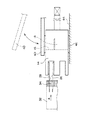
以下に本発明に係るサスペンションの保持用パレットに好適な具体的実施の形態を図面を参照して詳細に説明する。図1は、本実施の形態に係るサスペンションの保持用パレット10の使用形態を示す正面図である。同図に示すように本実施の形態に係る保持用パレット10は、平板形状からなるパレット本体12を基体としており、このパレット本体12上に種々の部材を搭載することで保持用パレット10を構成するようにしている。
Hereinafter, specific embodiments suitable for a suspension holding pallet according to the present invention will be described in detail with reference to the drawings. FIG. 1 is a front view showing a usage pattern of a
パレット本体12上は、サスペンションが取り付けられた2組のアクチュエータブロック14を並んで設置するだけの大きさを有しており、その中央部分には、前記アクチュエータブロック14に形成された取付穴16に嵌合する位置決めピン18が設けられている。なおアクチュエータブロック14に形成されている取付穴16はハードディスクへの組み付けの際、その内部にベアリングが挿入されるものであり内径は非常に精度良く加工されている。このため位置決めピン18を取付穴16に嵌合させることで、平面方向におけるパレット本体12に対するアクチュエータブロック14の取付位置を精度良く設定することができる。
The
そしてパレット本体12にアクチュエータブロック14を取り付けた後は、パレット本体12に設けられたレバー36を回転させれば、このレバー36の回転中心となるシャフト38に接続された押圧板40(図中、破線表示)がアクチュエータブロック14の上面に接触し、当該アクチュエータブロック14をパレット本体12に確実に固定することが可能になる。このようにレバー36、シャフト38、押圧板40とを有するブロック保持手段となるクランプ機構42を用いれば、簡単な構造でパレット本体12に形成されたブロック基準面44に、アクチュエータブロック14に形成された位置決め面46を密接させることが可能になる(図2を参照)。
After the
ところでアクチュエータブロック14には、コーム20と称されるクシ歯状の部材があらかじめ取り付けられている。そして当該コーム20は、アクチュエータブロック14に形成された孔部22に差し込み挿入可能な突起部24と、前記突起部24を回転中心としてアクチュエータブロック14に取り付けられた複数のサスペンション26、28(図2を参照)の間に挿入可能とし、前記サスペンション26、28の先端の接触防止をなす爪部30とを有しており、このコーム20をあらかじめアクチュエータブロック14に取り付けておくことで、サスペンション26、28の先端が接触するのを防止するようにしている。
By the way, a comb-like member called a
またパレット本体12には、アクチュエータブロック14の取付後方、且つ前記取付穴16とサスペンション26、28の先端とを結ぶ線上またはその近傍を回転(旋回)中心とする可動アーム32が設けられている。そしてこの可動アーム32の先端には、前記サスペンション26、28の間への挿入をなす挿入部材34が形成されており、可動アーム32の回転によりこの挿入部材34をサスペンションに対し出し入れ可能にしている。なお同図における左側のアクチュエータブロック14では、可動アーム32の位置は、挿入部材34がサスペンションから離れた際の状態を示し、一方同図における右側のアクチュエータブロック14では、可動アーム32の位置は、挿入部材34がサスペンション26、28の間に挿入された状態を示している。
The
なお、同図における右側のアクチュエータブロック14においては、可動アーム32は、挿入部材34がサスペンション26、28の間に差し込まれた位置にあるが、前記可動アーム32とパレット本体12との間には、外力が加わっても可動アーム32が回転し、挿入部材34がサスペンション26、28の間から外れるのを防止する構成を配置することが望ましい。
In the
さらに同図に示すように可動アーム32の回転により、挿入部材34の先端がコーム20の爪部30をサスペンション26、28の間から押し出すようにしているが可動アーム32にリンク機構等を形成しておき、挿入部材34がサスペンション26、28の間に挿入された際に、このリンク機構が矢印48に示す方向にコーム20を強制回転させるようにしてもよい。このような機構を追加すれば、コーム20の待避を可動アーム32の回転だけで行うことが可能になる。
Further, as shown in the figure, when the
図2は、アクチュエータブロックをパレット本体に装着した際の状態を示す側面図である。 FIG. 2 is a side view showing a state when the actuator block is mounted on the pallet body.
同図に示すようにアクチュエータブロック14の取付孔16を位置決めピン18に挿入するとともに、クランプ機構42を稼働させパレット本体12に形成されたブロック基準面44に、アクチュエータブロック14に形成された位置決め面46を密接させれば、アクチュエータブロック14をパレット本体12に固定することが可能になる。そしてアクチュエータブロック14をパレット本体12に固定した状態で、可動アーム32を回転させれば、可動アーム32の先端に形成された挿入部材34によってサスペンション26、28をあらかじめ設定された間隔で保持することができる。
As shown in the figure, the mounting
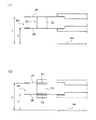
図3は、図2における挿入部材の矢視図Aであり、図4は、コームと挿入部材によるサスペンションの保持状態を示す説明図である。 FIG. 3 is an arrow A view of the insertion member in FIG. 2, and FIG. 4 is an explanatory view showing a suspension holding state by the comb and the insertion member.
サスペンション26は上方に曲げられており、対面するサスペンション28は下方(お互いが接触する向き)に取り付けられている。そしてこのサスペンション26、28の間隔を保つためにコーム20が取り付けられるのであるが、挿入部材34はコーム20が保持する取り付け高さ(図4における寸法B、寸法C)に対してさらにサスペンション26、28の間隔を正確な位置に保つようにしている(図4における寸法D、寸法E)。すなわちサスペンション26、28の先端の位置を正確に保持しないと、スライダの後付けをなすスライダチャック機構がサスペンション26、28の隙間54に入り込んだ際、スライダあるいはスライダチャック機構がサスペンション26、28に干渉したり、あるいはスライダが正確に実装できなくなるおそれがあるからである。
The
このため同図に示すように高精度に位置決めされた第1接触面50でサスペンション26の高さを設定し、また第1接触面50と同様、高精度に位置決めされた第2接触面52にてサスペンション28の高さを設定するようにしている。また第1接触面50および第2接触面52の対面側にはガイド板56、58が設けられており、スライダを実装する際にこれらサスペンション26、28が開き側にそらないように(逃げないように)反対側を受けるようになっている。
For this reason, as shown in the figure, the height of the
このため挿入部材34をサスペンション26、28の間に挿入した状態では、例えばスライダ取付対象となすサスペンション26と第1接触面50とは接触しているが、サスペンション26とガイド板56とはわずかな間隔を保っている。なお下方に設けられた他の挿入部材60は、サスペンションが4個取り付けられたアクチュエータブロック14を用いる場合を想定して設けられたものである。
Therefore, in a state where the
このような構成を有する保持用パレット10を用いれば、サスペンション先端の高さを正確に設定することができるので、スライダの後付けを確実に行うことができる。
If the holding
なお本実施の形態では、サスペンション26側のスライダの取付に対して説明を行うこととしたが、サスペンション28へのスライダの取付は、サスペンション28専用の保持用パレットを用いればよい。
In this embodiment, the description has been made with respect to the attachment of the slider on the
図5は、サスペンション28専用の保持用パレットの使用形態を示す正面図である。同図に示すように図1で述べた保持用パレット10に対し反転させた形態の保持用パレット62を形成すれば、サスペンション28に対してもサスペンション26と同様、スライダの後付けを容易に行うことが可能になる。なおクランプ機構42といったスライダの取付に寄与しない箇所は、保持用パレット10と同様の構造を適用すればよい。
FIG. 5 is a front view showing a usage pattern of the holding pallet dedicated to the
また本実施の形態では、可動アームにおける挿入部材が形成された側の反対側端部を中心として円運動をする方式にて説明を行ったが、この形態に限定されることもなく、対面したサスペンションの先端が接触しないよう前記サスペンションの間に差し込まれたコームを挿入部材に置き換えることができれば(さらに詳細には、サスペンションの先端の高さをあらかじめ設定した位置に保持できれば)、サスペンションに対する挿入部材の進入方向は設計上の都合等によって種々設定されればよい。具体的には、可動アームの端部を中心とした回転運動だけではなく、コームの爪部の延長方向に一致する直線運動であったり、あるいはカムやリンク機構等を用いて円運動と直線運動とを組み合わせた形態としてもよい。 Further, in the present embodiment, the description has been given by the method of performing a circular motion around the opposite end portion of the movable arm on the side where the insertion member is formed. If the comb inserted between the suspensions can be replaced with an insertion member so that the suspension tip does not come into contact (more specifically, if the height of the suspension tip can be maintained at a preset position), the insertion member for the suspension The approach direction may be set variously according to the design convenience. Specifically, it is not only a rotary motion centered on the end of the movable arm, but also a linear motion that matches the extension direction of the comb claw, or a circular motion and a linear motion using a cam or link mechanism, etc. And may be combined.
10………保持用パレット
12………パレット本体
14………アクチュエータブロック
16………取付孔
18………位置決めピン
20………コーム
22………孔部
24………突起部
26………サスペンション
28………サスペンション
30………爪部
32………可動アーム
34………挿入部材
36………レバー
38………シャフト
40………押圧板
42………クランプ機構
44………ブロック基準面
46………位置決め面
48………矢印
50………第1接触面
52………第2接触面
54………隙間
56………ガイド板
58………ガイド板
60………他の挿入部材
62………保持用パレット
10. Pallet for holding 12 ...
Claims (4)
パレット本体に前記アクチュエータブロックの位置決め面を前記パレット本体に形成されたブロック基準面に押圧するブロック保持手段を設けるとともに、前記パレット本体に可動アームを設け、この可動アームの先端に対面する複数の前記サスペンションの間に挿入可能とする挿入部材を形成し、前記スライダの取り付け対象となる前記サスペンションと接触する側に形成された第1接触面への前記サスペンションの接触により、前記スライダの取り付け対象となる前記サスペンションの先端を前記ブロック基準面からの規定高さに保持し、対面する前記サスペンションの間に隙間を形成するようにしたことを特徴とするサスペンションの保持用パレット。 A suspension holding pallet for holding the tip of the suspension attached to the actuator block at a preset height and attaching a slider constituting the magnetic head to the tip of the suspension,
The pallet body is provided with block holding means for pressing the positioning surface of the actuator block against a block reference surface formed on the pallet body, the pallet body is provided with a movable arm, and a plurality of the facing surfaces of the movable arm are opposed to each other. An insertion member that can be inserted between suspensions is formed, and the slider is attached by contact of the suspension with a first contact surface formed on a side that contacts the suspension to which the slider is attached. A suspension pallet for holding a suspension, wherein a tip of the suspension is held at a specified height from the block reference surface, and a gap is formed between the facing suspensions.
Priority Applications (3)
| Application Number | Priority Date | Filing Date | Title |
|---|---|---|---|
| JP2003402451A JP4137775B2 (en) | 2003-12-02 | 2003-12-02 | Suspension retention pallet |
| US10/997,901 US7453670B2 (en) | 2003-12-02 | 2004-11-29 | Suspension holder pallet |
| CNB2004100912920A CN1293537C (en) | 2003-12-02 | 2004-12-01 | Suspension holder pallet |
Applications Claiming Priority (1)
| Application Number | Priority Date | Filing Date | Title |
|---|---|---|---|
| JP2003402451A JP4137775B2 (en) | 2003-12-02 | 2003-12-02 | Suspension retention pallet |
Publications (2)
| Publication Number | Publication Date |
|---|---|
| JP2005166153A JP2005166153A (en) | 2005-06-23 |
| JP4137775B2 true JP4137775B2 (en) | 2008-08-20 |
Family
ID=34616745
Family Applications (1)
| Application Number | Title | Priority Date | Filing Date |
|---|---|---|---|
| JP2003402451A Expired - Fee Related JP4137775B2 (en) | 2003-12-02 | 2003-12-02 | Suspension retention pallet |
Country Status (3)
| Country | Link |
|---|---|
| US (1) | US7453670B2 (en) |
| JP (1) | JP4137775B2 (en) |
| CN (1) | CN1293537C (en) |
Cited By (2)
| Publication number | Priority date | Publication date | Assignee | Title |
|---|---|---|---|---|
| US7995638B2 (en) | 2005-10-28 | 2011-08-09 | Laserscope | High power, end pumped laser with off-peak pumping |
| US8897326B2 (en) | 2008-09-08 | 2014-11-25 | Ams Research Corporation | Pump energy wavelength stabilization |
Families Citing this family (6)
| Publication number | Priority date | Publication date | Assignee | Title |
|---|---|---|---|---|
| JP4486571B2 (en) * | 2005-09-08 | 2010-06-23 | 本田技研工業株式会社 | Suspension assembly positioning method |
| KR100734276B1 (en) * | 2005-10-10 | 2007-07-02 | 삼성전자주식회사 | HSA protecting member and method for installing HSA in hard disk drive using the same |
| US8089730B1 (en) * | 2009-10-28 | 2012-01-03 | Western Digital (Fremont), Llc | Suspension assembly having a read head clamp |
| US8514522B1 (en) | 2011-01-25 | 2013-08-20 | Western Digital (Fremont), Llc | Systems for interconnecting magnetic heads of storage devices in a test assembly |
| US20180240480A1 (en) * | 2017-02-23 | 2018-08-23 | Seagate Technology Llc | Slider test socket |
| US11105847B1 (en) | 2018-06-18 | 2021-08-31 | Seagate Technology Llc | Data storage component test socket opener |
Family Cites Families (16)
| Publication number | Priority date | Publication date | Assignee | Title |
|---|---|---|---|---|
| US4644429A (en) * | 1983-05-26 | 1987-02-17 | Applied Magnetics Corp. | Traversing apparatus for loading a magnetic head-loading arm assembly onto rotatable discs |
| US4956733A (en) * | 1985-07-29 | 1990-09-11 | Tandon Corporation | Storage media transducer loading/unloading and carriage lock mechanism |
| JP2751841B2 (en) | 1994-09-28 | 1998-05-18 | 日本電気株式会社 | Magnetic head insertion mechanism |
| CA2220304A1 (en) * | 1995-05-10 | 1996-11-14 | Iomega Corporation | Head loading mechanism for a disk drive |
| US5831795A (en) * | 1995-05-10 | 1998-11-03 | Iomega Corporation | Head loading mechanism for a disk drive |
| JP3344683B2 (en) * | 1995-06-07 | 2002-11-11 | インターナショナル・ビジネス・マシーンズ・コーポレーション | Actuator assembly and data storage system |
| GB9603508D0 (en) * | 1996-02-20 | 1996-04-17 | Myrica Uk Limited | Improvements in or relating to disk drives |
| US5826325A (en) * | 1997-07-10 | 1998-10-27 | International Business Machines Corporation | Method of merging heads |
| JPH1196528A (en) * | 1997-09-25 | 1999-04-09 | Internatl Business Mach Corp <Ibm> | Method for washing actuator arm assembly and actuator arm assembly |
| US6583963B2 (en) * | 1997-10-07 | 2003-06-24 | Seagate Technology Llc | Apparatus to improve shock capability of disc drives |
| JP2000163899A (en) * | 1998-11-30 | 2000-06-16 | Fujitsu Ltd | Driving device of recording disk |
| US6469872B1 (en) * | 1999-06-24 | 2002-10-22 | Seagate Technology Llc | Featherweight actuator for disc drives |
| US6452753B1 (en) * | 2001-08-06 | 2002-09-17 | Maxtor Corporation | Universal load/unload ramp |
| WO2003042996A1 (en) * | 2001-11-13 | 2003-05-22 | Sae Magnetics (H.K.) Ltd. | Universal fixture for hsa assembly and its testing process |
| US7159299B1 (en) * | 2002-12-10 | 2007-01-09 | Maxtor Corporation | Spring assisted head stack assembly comb |
| KR100585167B1 (en) * | 2004-12-07 | 2006-06-01 | 삼성전자주식회사 | Shipping comb for moving actuator of hard disk drive |
-
2003
- 2003-12-02 JP JP2003402451A patent/JP4137775B2/en not_active Expired - Fee Related
-
2004
- 2004-11-29 US US10/997,901 patent/US7453670B2/en not_active Expired - Fee Related
- 2004-12-01 CN CNB2004100912920A patent/CN1293537C/en not_active Expired - Fee Related
Cited By (3)
| Publication number | Priority date | Publication date | Assignee | Title |
|---|---|---|---|---|
| US7995638B2 (en) | 2005-10-28 | 2011-08-09 | Laserscope | High power, end pumped laser with off-peak pumping |
| US8897326B2 (en) | 2008-09-08 | 2014-11-25 | Ams Research Corporation | Pump energy wavelength stabilization |
| US9407058B2 (en) | 2008-09-08 | 2016-08-02 | Boston Scientific Scimed, Inc. | Pump energy wavelength stabilization |
Also Published As
| Publication number | Publication date |
|---|---|
| US7453670B2 (en) | 2008-11-18 |
| JP2005166153A (en) | 2005-06-23 |
| CN1624768A (en) | 2005-06-08 |
| CN1293537C (en) | 2007-01-03 |
| US20050117254A1 (en) | 2005-06-02 |
Similar Documents
| Publication | Publication Date | Title |
|---|---|---|
| JP4137775B2 (en) | Suspension retention pallet | |
| JP5239547B2 (en) | Chip holder, holder unit, scribe head, and scribe device | |
| US5347413A (en) | De-swaging technique for head gimbal assembly | |
| US7872830B2 (en) | Magnetic medium stack assembly for a data storage and retrieval system | |
| US6456463B1 (en) | Actuator assembly having an arm with a spring mount for mounting to an assembly spacer | |
| JP3913245B2 (en) | Disc chucking device for disc drive | |
| US11152022B2 (en) | Warp correction apparatus for plate-like workpiece and warp correction method | |
| US6790133B2 (en) | Suspension assembly for magnetic disk glide and burnish applications | |
| US5465477A (en) | Method of assembling a head arm stack for a magnetic disk drive | |
| CN115365856B (en) | Tool changer | |
| US9656367B2 (en) | Universal carrier device and adaptive components for the carrier device | |
| CN1315113C (en) | Method of manufacturing a magnetic head, and magnetic head manufacturing apparatus | |
| TWI765709B (en) | Cutting tool changing device and operating method for cutting tool changing device | |
| JP3832297B2 (en) | Electronic component assembly equipment | |
| US20080034580A1 (en) | Suspension-terminal connecting apparatus and method of manufacturing suspension assembly | |
| JP4180587B2 (en) | Cutting method of stick-shaped wafer | |
| JP3607587B2 (en) | Magnetic head manufacturing apparatus and transport system used for the apparatus | |
| JP2000011569A (en) | Servo writer | |
| JP6226204B2 (en) | Head stack assembly manufacturing equipment | |
| JP2006318609A (en) | Method for reworking magnetic head assembly with jogging actuator | |
| US9269402B1 (en) | BVCM hold down apparatus to prevent pivot bearing damage at TVCM installation in disk drive assembly | |
| JPH05217134A (en) | Clamping mechanism for magnetic head | |
| US20110286124A1 (en) | Magnetic recording medium and magnetic recording medium manufacturing method | |
| JPH08102003A (en) | Production of magnetic head | |
| JP2006116616A (en) | Polishing tool of slider, polishing device and polishing method |
Legal Events
| Date | Code | Title | Description |
|---|---|---|---|
| A621 | Written request for application examination |
Free format text: JAPANESE INTERMEDIATE CODE: A621 Effective date: 20050913 |
|
| A711 | Notification of change in applicant |
Free format text: JAPANESE INTERMEDIATE CODE: A711 Effective date: 20071015 |
|
| A521 | Request for written amendment filed |
Free format text: JAPANESE INTERMEDIATE CODE: A821 Effective date: 20071015 |
|
| A977 | Report on retrieval |
Free format text: JAPANESE INTERMEDIATE CODE: A971007 Effective date: 20071203 |
|
| A131 | Notification of reasons for refusal |
Free format text: JAPANESE INTERMEDIATE CODE: A131 Effective date: 20080116 |
|
| A521 | Request for written amendment filed |
Free format text: JAPANESE INTERMEDIATE CODE: A523 Effective date: 20080416 |
|
| TRDD | Decision of grant or rejection written | ||
| A01 | Written decision to grant a patent or to grant a registration (utility model) |
Free format text: JAPANESE INTERMEDIATE CODE: A01 Effective date: 20080602 |
|
| A01 | Written decision to grant a patent or to grant a registration (utility model) |
Free format text: JAPANESE INTERMEDIATE CODE: A01 |
|
| A61 | First payment of annual fees (during grant procedure) |
Free format text: JAPANESE INTERMEDIATE CODE: A61 Effective date: 20080604 |
|
| R150 | Certificate of patent or registration of utility model |
Ref document number: 4137775 Country of ref document: JP Free format text: JAPANESE INTERMEDIATE CODE: R150 Free format text: JAPANESE INTERMEDIATE CODE: R150 |
|
| FPAY | Renewal fee payment (event date is renewal date of database) |
Free format text: PAYMENT UNTIL: 20110613 Year of fee payment: 3 |
|
| FPAY | Renewal fee payment (event date is renewal date of database) |
Free format text: PAYMENT UNTIL: 20110613 Year of fee payment: 3 |
|
| FPAY | Renewal fee payment (event date is renewal date of database) |
Free format text: PAYMENT UNTIL: 20120613 Year of fee payment: 4 |
|
| R250 | Receipt of annual fees |
Free format text: JAPANESE INTERMEDIATE CODE: R250 |
|
| FPAY | Renewal fee payment (event date is renewal date of database) |
Free format text: PAYMENT UNTIL: 20120613 Year of fee payment: 4 |
|
| FPAY | Renewal fee payment (event date is renewal date of database) |
Free format text: PAYMENT UNTIL: 20130613 Year of fee payment: 5 |
|
| R250 | Receipt of annual fees |
Free format text: JAPANESE INTERMEDIATE CODE: R250 |
|
| R250 | Receipt of annual fees |
Free format text: JAPANESE INTERMEDIATE CODE: R250 |
|
| R250 | Receipt of annual fees |
Free format text: JAPANESE INTERMEDIATE CODE: R250 |
|
| R250 | Receipt of annual fees |
Free format text: JAPANESE INTERMEDIATE CODE: R250 |
|
| R250 | Receipt of annual fees |
Free format text: JAPANESE INTERMEDIATE CODE: R250 |
|
| R250 | Receipt of annual fees |
Free format text: JAPANESE INTERMEDIATE CODE: R250 |
|
| R250 | Receipt of annual fees |
Free format text: JAPANESE INTERMEDIATE CODE: R250 |
|
| R250 | Receipt of annual fees |
Free format text: JAPANESE INTERMEDIATE CODE: R250 |
|
| LAPS | Cancellation because of no payment of annual fees |