JP4136553B2 - Bag laying device - Google Patents
Bag laying device Download PDFInfo
- Publication number
- JP4136553B2 JP4136553B2 JP2002261035A JP2002261035A JP4136553B2 JP 4136553 B2 JP4136553 B2 JP 4136553B2 JP 2002261035 A JP2002261035 A JP 2002261035A JP 2002261035 A JP2002261035 A JP 2002261035A JP 4136553 B2 JP4136553 B2 JP 4136553B2
- Authority
- JP
- Japan
- Prior art keywords
- bag
- bag body
- container
- opening
- box
- Prior art date
- Legal status (The legal status is an assumption and is not a legal conclusion. Google has not performed a legal analysis and makes no representation as to the accuracy of the status listed.)
- Expired - Fee Related
Links
Images


Description
【0001】
【発明の属する技術分野】
この発明は、例えば段ボール紙製又は厚紙製の箱体、合成樹脂製又は金属製のコンテナケース等の容器内部に、合成樹脂や紙等の単一又は複合した材質で形成した袋体を敷設する作業に用いられる袋敷設装置に関する。
【0002】
【従来の技術】
従来、上述の袋体を敷設する装置としては、例えば箱体内部と略対応するサイズに分離した袋体の口部を、袋体搬送機構の上爪で保持して所定長さ引き出し、袋体拡開機構の吸着器で吸着保持して開口する。続いて、袋体の口部を、袋体下降機構の下爪で開口保持して引き下げ、上面側が開放された箱体の開放側周縁部に被覆すると共に、その袋体の底部側を、送風機から吹出されるエアーで表裏反転し、箱体内部に挿入及び敷設する袋敷設装置がある。
【0003】
【特許文献1】
特開平11−138664号公報。
【0004】
【発明が解決しようとする課題】
しかし、上述の装置は、袋体下降機構の下爪により開口保持された袋体を、送風機から吹出されるエアーの吐出力により表裏反転して箱体内部に挿入及び敷設するので、袋体と箱体との対向面間に空気が残留しやすく、袋体を、箱体の内側内壁面に沿った状態又は略密着した状態に装填することが難しい。且つ、様々なサイズを有する箱体に応じて専用の装置を設計しなければならず、製作コストが高くなる。
【0005】
この発明は上記問題に鑑み、袋体を容器内部と略対応する大きさに袋体拡張手段で拡張したまま、該袋体内部に挿入した袋拡張手段を容器の内側底部に対して近接される深さに挿入することにより、容器内部と略同等の容積率を確保する状態に敷設することができる袋敷設装置の提供を目的とする。
【0006】
【課題を解決するための手段】
この発明は、袋体の口部を外側に折り返して容器の開放側周縁部に被覆し、該袋体の底部を容器の内壁面に沿った状態に敷設する袋敷設装置であって、上記容器と略対応する大きさに形成された袋体の口部を開口する袋開口手段と、上記袋開口手段により開口された袋体の内側底部に対して近接される深さに挿入される挿入体と、上記挿入体を上記袋体への挿入が許容される近接状態と、該袋体の略全体を容器内部と略対応する大きさに拡張される離間状態とに拡縮動作する袋拡張手段と、上記袋開口手段により開口された袋体の口部を容器の開放側縁部に対して被覆が許容される大きさに開口し、該袋体の口部を外側に折り返して容器の開放側縁部に被覆する袋被せ手段と、上記袋体内部に挿入された袋拡張手段を、上記容器の内側底部に対して近接される深さに挿入する移動手段とを備えた袋敷設装置であることを特徴とする。
【0007】
上述の袋体は、例えば容器内部と略対応する大きさに形成した袋体、長さ方向に連続する略筒状のフィルム原反を容器内部と略対応する大きさに分離した袋体で構成することができる。且つ、その袋体は、例えば合成樹脂や紙等の材質を単一又は複合したもので構成することができる。また、容器は、例えば段ボール紙製や厚紙製の箱体、プラスチック製や金属製、木製のコンテナ等で構成することができる。また、袋開口手段及び袋被せ手段は、例えば吸着子や折返し板、アーム、チャック等で構成することができる。また、袋拡張手段は、例えば略棒状又は略板状の挿入体、挿入枠、挿入部材等で構成することができる。また、移動手段及び相対移動手段は、例えばエアーシリンダやソレノイド、チェーン、ネジ軸、レール、カム、モータ、クランク機構、リンク機構等で構成することができる。
【0008】
つまり、容器(例えば段ボール紙製の箱体)と略対応する大きさに形成した袋体の口部を袋開口手段で開口し、袋拡張手段の挿入体を袋体への挿入が許容される近接状態に近接して、袋開口手段により開口された袋体内部の内側底部に対して近接される深さに挿入した後、袋体に挿入された挿入体を、袋体の略全体が容器内部と略対応する大きさに拡張される離間状態に離間して、袋体を容器内部と略対応する大きさに拡張する。且つ、袋体内部に挿入した袋拡張手段を、容器の内側底部に対して近接される深さに移動手段により移動及び挿入し、袋体を容器の内壁面に沿った状態及び略密着した状態に装填する。且つ、袋体の口部を、容器の開放側縁部に対して被覆が許容される大きさに袋被せ手段で開口し、袋体の口部を外側に折り返して、容器の開放側縁部に対してダブル折り状態又はシングル折り状態に被覆する。
【0009】
実施の形態として、上記袋開口手段により開口される袋体と、該袋体内部に挿入される上記袋拡張手段とを、該袋体内部に対して袋拡張手段が挿入される方向(例えば上下方向や水平方向)に相対移動する相対移動手段を備えることができる。また、上記袋開口手段の前段に、長さ方向に連続する略筒状の包装体(例えばロール状に巻回又は扁平状態に折り畳まれた略筒状のフィルムや包装紙等)を、上記容器と略対応する大きさに分離して供給する袋分離手段(例えば切断刃及び加熱ヘッド、カッタやハサミ等の切断具)を備えることができる。また、上記袋被せ手段により開口及び保持された袋体の敷設が許容される位置に、上記容器を搬送する容器搬送手段(例えばチェーンコンベアやベルトコンベア、ローラコンベア等の搬送手段)を備えることができる。
【0010】
【作用及び効果】
この発明によれば、袋体を、容器内部と略対応する大きさに袋体拡張手段で拡張したまま、その袋体内部に挿入した袋拡張手段を、容器の内側底部に対して近接される深さに挿入するので、袋体と容器との対向面間に空気が残留せず、袋体を、容器内壁面に沿った状態及び略密着した状態に確実且つ正確に敷設することができ、容器内部と略同等の容積率を確保することができる。且つ、袋体を、様々なサイズを有する容器に対して敷設する作業が安定して行え、袋体の敷設精度の向上を図ることができる。
【0011】
【実施例】
この発明の一実施例を以下図面に基づいて詳述する。
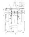
図面は、容器の一例である上面側が開放された箱体内部に袋体を敷設する作業に用いられる袋敷設装置を示し、図1に於いて、この袋敷設装置1は、ロール状に巻回されたフィルム原反fを供給する供給機構10と、フィルム原反fを箱体Bと略対応するサイズに熱シールするシール機構20と、フィルム原反fを箱体Bと略対応するサイズに分離する分離機構30と、フィルム原反f及び袋体Fを開口しながら所定高さに引上げる引上げ機構40と、袋体Fの口部Faを、上面側が開放された箱体Bに対して被覆及び装填する袋被せ機構50と、上述の箱体Bを袋被せ機構50下部に搬送する搬送コンベア70とで構成される。
【0012】
上述の供給機構10は、扁平状態(例えばガゼット折り状態又は平折り状態)に折り畳まれ、ロール状に巻回された透光性を有する合成樹脂製のフィルム原反fを、原反供給路の始端部に設けた装填部11に装填し、その装填部11から引き出されるフィルム原反fを、ガイドロール12と、送りロール13と、押えロール14と、ダンサーロール15とを介して、供給路上のシール位置aに配設したシール機構20と、分離位置bに配設した分離機構30とに供給する。また、フィルム原反fの代わりに、例えば所定サイズに形成した袋体Fを1枚ずつ供給するか、紙製又は合成樹脂を複合した袋体Fを供給してもよい。
【0013】
前述のシール機構20は、シール位置aに供給されるフィルム原反fの上下面を押え部材21及び受け部材22で押圧し、その押圧部後位を受け部材22及び加熱ヘッド23で押圧して、フィルム原反fを、箱体Bと略対応する長さ位置で幅方向に熱シールする。且つ、シール位置a後位の送りロール25及び押えロール26は、フィルム原反fを分離機構30に供給する方向に回転する。
【0014】
前述の分離機構30は、図5にも示すように、例えば吸気ブロワ又は真空ポンプ等の負圧発生装置(図示省略)に接続された一対の吸着子34を、分離位置b両側部に架設した側面から見て上下逆ハ字状のレール35に対して上下動可能に取付け、例えばクランク機構やリンク機構等の昇降手段により、分離位置bに供給されるフィルム原反fの開口側縁部を吸着保持する間隔に近接しながら降下位置に降下動作し、後述する引上げアーム44によりフィルム原反fの開口側縁部が保持される間隔に開口しながら上昇位置に上昇動作する。且つ、上昇時において、一方の吸着子34を先行して上昇させ、フィルム原反fの開口側縁部を一対の吸着子34により面方向にずらせて剥離及び開口を容易にする。
【0015】
且つ、フィルム原反fが引上げアーム44により箱体B内部と略対応する長さ引上げられ、そのフィルム原反fのシール部下位が一対の吸着子34で吸着保持されたとき、一方の吸着子34上部に取り付けられた切断刃32を、該吸着子34後部に取り付けた進退シリンダ33により前後移動又は左右移動して、引上げアーム44により引上げられたフィルム原反fのシール部と、一対の吸着子34で吸着保持されたフィルム原反fの開口側縁部との間を幅方向に切断し、一つの袋体Fに分離する。
【0016】
前述の引上げ機構40は、一対の引上げアーム44を、分離機構30両側部に立設した支持レール41に対して上下動可能に取付け、例えばチェーンやネジ軸等の昇降手段により、一対の吸着子34により開口されたフィルム原反fの開口側縁部を保持する降下位置と、後述する被せユニット53によりフィルム原反fの開口側縁部が保持される上昇位置とに上下動する。
【0017】
且つ、一対の引上げアーム44は、一対の吸着子34により開口されたフィルム原反fの開口側内縁部に挿入される挿入アーム45と、そのフィルム原反fの開口側外縁部に押圧される押圧アーム46とで構成される。一対の吸着子34が上昇動作するとき、例えばカムやギャ等の開閉手段により開閉動作される。また、例えばエアーシリンダやカム等の開閉手段により、上昇位置及び降下位置において、一対の吸着子34により開口されたフィルム原反fの開口側縁部を挟持する閉状態と、その挟持が解除される開状態とに開閉動作する。
【0018】
且つ、一対の引上げアーム44を、支持レール41側部に架設した案内レール42に沿って上下動させ、上昇時において、後述する被せユニット53によりフィルム原反fの開口側縁部が保持される間隔に離間し、降下時において、一対の吸着子34により開口したフィルム原反fの開口側縁部が挟持される間隔に近接する。
【0019】
前述の袋被せ機構50は、図2、図3、図4にも示すように、袋体Fの口部Faを、箱体Bの開放側縁部に連設されたフラップBa…に被覆する被せユニット53と、袋体F全体を箱体B内部と略対応する大きさに拡張して装填する装填ユニット54とを、上述の引上げ機構40上部に架設した下側昇降枠51及び上側昇降枠52に垂設している。
【0020】
且つ、下側昇降枠51の被せユニット53及び上側昇降枠52の装填ユニット54を、例えばサーボモータやエアーシリンダ等の移動手段により、一対の引上げアーム44により引上げられたフィルム原反f及び袋体Fの開口側縁部を保持する後退位置と、搬送コンベア70上の敷設位置cに搬送された箱体Bに対する袋体Fの装填が許容される前進位置とに前後動する。
【0021】
且つ、例えばチェーンやネジ軸等の昇降手段により、箱体B内部と略対応する大きさに袋体Fの拡張動作が許容される上昇位置と、敷設位置cに搬送された箱体B内部に対して袋体Fの装填が許容される降下位置とに昇降動作する。また、被せユニット53及び装填ユニット54は、箱体B及び袋体Fのサイズに略対応して拡縮調節される。
【0022】
上述の被せユニット53は、一つに分離された袋体Fの口部Faに挿入される側面から見て略爪状の折返し板53a…と、袋体Fの口部Faを保持する4組の折返しチャック53b,53bとで構成される。且つ、折返し板53a…は、例えばネジ軸やサーボモータ等の移動手段により、折返しチャック53b,53bと一緒に前後移動され、一対の引上げアーム44により引上げられるフィルム原反f及び袋体Fに対して挿入が許容される近接状態と、箱体Bの角隅部外壁面に沿って袋体Fが略垂直挿入される離間状態とに拡縮動作される。
【0023】
一方、折返しチャック53b,53bは、例えばエアーシリンダやソレノイド等の回動手段により、一対の引上げアーム44により引上げられるフィルム原反fの開口側縁部を保持する下向き姿勢と、箱体BのフラップBa…に対する袋体Fの口部Faが被覆許容される内向き姿勢とに揺動される。
【0024】
且つ、袋体Fの口部Faを折返し板53a…に対して押し付け、箱体BのフラップBaを略鉛直に起立する姿勢に矯正するガイド板53cを、折返し板53a外面と対向して複数取り付けている。
【0025】
前述の装填ユニット54は、上述の折返し板53a…よりも内側に垂設した側面から見て略棒状又は略板状の挿入体54a…を、一対の吸着子34で開口されるフィルム原反f内部に対して挿入許容され、袋体F全体を箱体B内部と略対応する大きさに拡張するのに適した長さ及び袋体Fの内側底部に達する長さに形成している。且つ、挿入体54aは、例えばネジ軸やサーボモータ等の移動手段により、折返し板53a…及び折返しチャック53b,53bと一緒に、一対の引上げアーム44により引上げられるフィルム原反f及び袋体Fに対して挿入が許容される近接状態と、箱体B内部と略対応する大きさに袋体Fの拡張及び箱体Bの角隅部内壁面に沿って袋体Fが略垂直挿入される離間状態とに拡縮動作する。
【0026】
前述の搬送コンベア70は、図1、図2に示すように、箱体Bが載置される間隔に隔てて搬送方向に平行して張架した送りベルト71…を、減速機付きモータ(図示省略)により搬送方向に同期回転して、製函工程(図示省略)から供給される上面側が開放された箱体Bを、前述の被せユニット53…により開口保持された袋体F下部であって、搬送路上に設定した装填位置cに対して1個ずつ搬送し、袋敷設済みの箱体Bを次工程(例えば箱詰め工程や袋詰め工程等)に搬送する。且つ、箱体Bを、例えばプッシャーやアーム、ガイド等の幅寄せ手段により基準位置側に幅寄せすることもできる。
【0027】
且つ、箱体Bが載置される昇降台72を、敷設位置cに張架した送りベルト71…の間に配設して、例えばネジ軸又はエアーシリンダ等の昇降手段により、送りベルト71…の搬送面上に突出する状態と、搬送面下に没入する状態とに上下動する。
【0028】
図示実施例は上記の如く構成するものにして、以下、袋敷設装置1による袋体Fの敷設動作を説明する。
先ず、図1、図2にも示すように、供給機構10を駆動して、装填部11から繰出されるフィルム原反fをシール機構20及び分離機構30に供給する。且つ、図5、図6、図7にも示すように、分離位置bに供給されるフィルム原反fの開口側縁部を、分離機構30を構成する一対の吸着子34で吸着保持して面方向に変位させて開口し、予め待機させた装填ユニット54の挿入体54a…をフィルム原反f内部に挿入する。且つ、フィルム原反fが箱体B内部と略対応する長さ繰出されたとき、シール位置aに供給されるフィルム原反fを、シール機構20の加熱ヘッド23で加熱して幅方向に熱シールする。
【0029】
次に、一対の吸着子34で開口したフィルム原反fの開口側縁部を、引上げ機構40を構成する一対の引上げアーム44で挾持して所定高さに引上げて、図8の(イ,ロ)にも示すように、上述の挿入体54a…の略全長を、フィルム原反fの内側底部に対して近接される深さに挿入する。この後、一対の吸着子34による吸着を解除して初期位置に復帰させる。
【0030】
次に、一対の引上げアーム44で引上げたフィルム原反fの開口側縁部を、袋被せ機構50を構成する被せユニット53の折返しチャック53b,53bで挟持し、折返し板53a…をフィルム原反fに挿入すると共に、袋体Fの口部Faを、ガイド板53c…で折返し板53a…に対して押し付ける。且つ、フィルム原反fが所定高さに引上げられたとき、フィルム原反fのシール部下位を分離機構30の切断刃32で切断し、一つの袋体Fに分離する。この後、一対の引上げアーム44による保持を解除して初期位置に復帰させる。
【0031】
次に、4組の折返しチャック53b,53bで挟持した袋体Fを、搬送コンベア70上の敷設位置cに搬送される箱体B上部に移動させる。且つ、図9の(ハ,ニ)及び図10にも示すように、袋体Fの口部Faを、4組の折返し板53a…及び折返しチャック53b,53bにより箱体BのフラップBa…に対して被覆許容される大きさに開口する。且つ、袋体F全体を、装填ユニット54の挿入体54a…により箱体B内部と略対応する大きさに拡張する。
【0032】
次に、図4、図11、図12にも示すように、袋体Fを、箱体B内部と略対応する大きさに拡張及び保持したまま、被せユニット53及び装填ユニット54を降下させ、被せユニット53の折返し板53a…及び装填ユニット54の挿入体54a…を箱体Bの角隅部内壁面に沿って垂直挿入すると共に、挿入体54a…を、箱体Bの内側底部に対して所定間隔に近接される深さまで降下して、袋体Fを、箱体B内壁面に沿った状態及び略密着した状態に装填する。且つ、袋体Fと箱体Bとの対向面間に残留する空気抜き取り、箱体B内部と略同等の容積率を確保する。
【0033】
且つ、箱体BのフラップBaを、ガイド板53c…により略鉛直に起立する姿勢に矯正し、ダブル折り可能な袋体Fの口部Faを、折返し板53a…により外側に折り返して、箱体BのフラップBa…外面に対してダブル折り状態に被覆し、箱体Bの内壁部及び角隅部に沿った状態に敷設(図13参照)する。また、シングル折り可能な袋体Fの口部Faを、箱体BのフラップBa…外面に対してシングル折り状態に被覆及び敷設(図14参照)することもできる。
【0034】
次に、折返しチャック53b,53bによる挟持を解除して、被せユニット53…及び装填ユニット54を初期位置に復帰させると共に、袋敷設済みの箱体Bを搬送コンベア70により次工程に搬送する。以下、上述と同様にして、機構10,20,30,40,50を動作して、袋体Fの敷設作業を継続して行う。
【0035】
以上のように、袋体Fを、箱体B内部と略対応する大きさに袋被せ機構50の折返し板53a…及び挿入体54a…で拡張したまま、その袋体F内部に挿入した挿入体54a…を、箱体Bの内側底部に対して近接される深さに挿入して装填するので、袋体Fと箱体Bとの対向面間に空気が残留せず、袋体Fを、箱体B内壁面に沿った状態及び略密着した状態に確実且つ正確に敷設することができ、箱体B内部と略同等の容積率を確保することができる。且つ、袋体Fを、様々なサイズを有する容器に対して敷設する作業が安定して行え、袋体Fの敷設精度の向上を図ることができる。
【0036】
且つ、袋被せ機構50の折返し板53a…及び挿入体54a…で保持した袋体Fを降下して箱体B内部に敷設するので、特定サイズを有する箱体B専用の装置を設計したり、オーダーによる設計変更が不要であり、袋体Fを、様々なサイズを有する箱体Bに敷設する作業が一つの装置で行える。
【0037】
且つ、長さ方向に連続するフィルム原反fを上方に引上げて一つの袋体Fに分離するので、装置の設置スペースが小さくて済み、シンプル且つコンパクトに設計することができると共に、構造及び構成が簡単であるため、低コストで製作することができる。
【0038】
図15は、袋体Fの口部Faを、折返し板53a…及び押付け板53d…で挟持して拡張する袋被せ機構50の他の方法を示し、被せユニット53の折返し板53a…を、一対の引上げアーム44により引上げられた袋体Fの口部Faに挿入し、折返し板53a…側部に枢着した押付け板53d…を、例えばエアーシリンダやソレノイド等の回動手段により折返し板53a…と対向する方向に回動して、袋体Fの口部Faを、接触抵抗の大きい押圧パッド53e…を介して、折返し板53a…及び押付け板53d…により挟持するので、袋体Fの口部Faを、箱体BのフラップBa…に対して被覆可能な大きさに開口することができ、上述の実施例と略同等の作用及び効果を奏することができる。
【図面の簡単な説明】
【図1】 袋敷設装置による袋体の敷設動作を示す正面図。
【図2】 袋被せ機構の被せ動作及び搬送コンベアの搬送動作を示す側面図。
【図3】 袋被せ機構による拡張動作及び被せ動作を示す平面図。
【図4】 袋体の装填動作及び折返し動作を示す正面図。
【図5】 一対の吸着子によるフィルム原反の吸着状態を示す側面図。
【図6】 一対の吸着子によるフィルム原反の開口動作を示す側面図。
【図7】 一対の引上げアームによるフィルム原反の挟持動作を示す側面図。
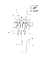
【図8】 袋体の引上げ動作及び挿入棒の挿入動作を示す斜視図。
【図9】 袋体の分離動作及び移動動作を示す斜視図。
【図10】 袋体の拡張動作を示す斜視図。
【図11】 袋体の挿入動作を示す斜視図。
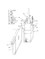
【図12】 袋体の口部をダブル折り状態に折返す動作を示す斜視図。
【図13】 袋体の口部をダブル折り状態に被せた状態を示す斜視図。
【図14】 袋体の口部をシングル折り状態に被せた状態を示す斜視図。
【図15】 袋被せ機構による他の被せ方法を示す側面図。
【符号の説明】
f…フィルム原反
F…袋体
Fa…口部
B…箱体
Ba…フラップ
1…袋敷設装置
30…分離機構
34…吸着子
40…引上げ機構
44…引上げアーム
50…袋被せ機構
53…被せユニット
53a…折返し板
53b…折返しチャック
53d…押付け板
54…装填ユニット
54a…挿入体
70…搬送コンベア[0001]
BACKGROUND OF THE INVENTION
In the present invention, for example, a bag formed of a single or composite material such as synthetic resin or paper is laid in a container such as a corrugated cardboard or cardboard box, or a synthetic resin or metal container case. The present invention relates to a bag laying device used for work.
[0002]
[Prior art]
Conventionally, as an apparatus for laying the above-described bag body, for example, the mouth portion of the bag body separated into a size substantially corresponding to the inside of the box body is held by the upper nail of the bag body transport mechanism and pulled out to a predetermined length. It opens by suction and holding with an adsorber of a spreading mechanism. Subsequently, the mouth portion of the bag body is held open by the lower claws of the bag body lowering mechanism and pulled down to cover the opening side peripheral edge portion of the box body whose upper surface side is opened, and the bottom side of the bag body is blown to the blower There is a bag laying device that reverses the front and back with air blown from and inserted and laid inside the box.
[0003]
[Patent Document 1]
JP-A-11-138664.
[0004]
[Problems to be solved by the invention]
However, the above-mentioned device inserts and lays the bag body, which is held open by the lower claws of the bag body lowering mechanism, into the box body by reversing the front and back by the discharge force of the air blown from the blower. Air tends to remain between the surfaces facing the box, and it is difficult to load the bag in a state along or substantially in close contact with the inner inner wall surface of the box. In addition, a dedicated device must be designed according to the box having various sizes, which increases the manufacturing cost.
[0005]
In view of the above problem, the present invention brings the bag expanding means inserted into the bag body close to the inner bottom of the container while the bag body is expanded to a size approximately corresponding to the inside of the container by the bag expanding means. It aims at providing the bag laying apparatus which can be laid in the state which ensures the volume ratio substantially equivalent to the inside of a container by inserting in depth.
[0006]
[Means for Solving the Problems]
The present invention is a bag laying device that folds the mouth portion of the bag body outward to cover the peripheral edge of the open side of the container, and lays the bottom portion of the bag body along the inner wall surface of the container. substantially a bag opening means for opening the mouth of the corresponding size which is formed in the bag body, the insert that will be inserted to a depth that is close to the inner bottom portion of the apertured bag by the bag opening means and And a bag expanding means that expands and contracts into a proximity state in which the insertion body is allowed to be inserted into the bag body, and a separated state in which substantially the entire bag body is expanded to a size substantially corresponding to the inside of the container. The opening of the bag body opened by the bag opening means is opened to a size that allows the covering to the opening side edge of the container, and the opening of the bag body is folded back to the outside. A bag covering means for covering the edge portion and a bag expanding means inserted into the bag body are provided on the inner bottom of the container. Characterized in that it is a bag laying apparatus and a moving means for inserting the depth is close to is.
[0007]
The above-mentioned bag body is constituted by, for example, a bag body formed in a size substantially corresponding to the inside of the container, and a bag body obtained by separating a substantially cylindrical film raw material continuous in the length direction into a size substantially corresponding to the inside of the container. can do. And the bag body can be comprised by what single or combined materials, such as a synthetic resin and paper, for example. Further, the container can be constituted by, for example, a box made of corrugated paper or cardboard, a plastic, metal, wooden container or the like. Moreover, the bag opening means and the bag covering means can be constituted by, for example, an adsorber, a folded plate, an arm, a chuck, or the like. Further, the bag expanding means can be constituted by, for example, a substantially rod-like or substantially plate-like insert, an insertion frame, an insertion member, or the like. Further, the moving means and the relative moving means can be constituted by, for example, an air cylinder, a solenoid, a chain, a screw shaft, a rail, a cam, a motor, a crank mechanism, a link mechanism, or the like.
[0008]
That is, the opening of the bag body formed in a size substantially corresponding to the container (for example, a box made of cardboard paper) is opened by the bag opening means, and the insertion body of the bag expanding means is allowed to be inserted into the bag body. Insert the inserted body inserted into the bag body after being inserted to a depth close to the inner bottom portion inside the bag body opened by the bag opening means in the vicinity of the proximity state. The bag body is expanded to a size substantially corresponding to the inside of the container by being separated into a separated state expanded to a size substantially corresponding to the inside. In addition, the bag expanding means inserted into the bag body is moved and inserted by the moving means to a depth close to the inner bottom of the container, and the bag body is in a state along and substantially in close contact with the inner wall surface of the container. To load. Further, the opening of the bag body is opened by the bag covering means to a size that allows the covering to the opening side edge of the container, and the opening of the bag body is folded back to the outside. Are covered in a double fold state or a single fold state.
[0009]
As an embodiment, a bag body opened by the bag opening means and the bag expanding means inserted into the bag body are arranged in the direction in which the bag expanding means is inserted into the bag body (for example, up and down Relative moving means for moving in the horizontal direction). In addition, a substantially cylindrical packaging body (for example, a substantially cylindrical film or wrapping paper wound in a roll shape or folded in a flat state) continuous in the length direction is placed in front of the bag opening means. And a bag separation means (for example, a cutting blade and a heating head, a cutting tool such as a cutter or scissors). In addition, a container conveying means (for example, a conveying means such as a chain conveyor, a belt conveyor, or a roller conveyor) that conveys the container is provided at a position where the laying of the bag body that is opened and held by the bag covering means is allowed. it can.
[0010]
[Action and effect]
According to the present invention, the bag expanding means inserted into the bag body is brought close to the inner bottom of the container while the bag body is expanded to a size substantially corresponding to the inside of the container by the bag expanding means. Since it is inserted at a depth, air does not remain between the facing surfaces of the bag body and the container, and the bag body can be reliably and accurately laid in a state along the inner wall surface of the container and in a substantially closely contacted state, A volume ratio substantially equal to the inside of the container can be ensured. And the operation | work which lays a bag with respect to the container which has various sizes can be performed stably, and the improvement of the laying accuracy of a bag can be aimed at.
[0011]
【Example】
An embodiment of the present invention will be described below in detail with reference to the drawings.
The drawing shows a bag laying device used for laying a bag body inside a box body whose upper surface side is an example of a container. In FIG. 1, this bag laying device 1 is wound in a roll shape.
[0012]
The
[0013]
The above-described
[0014]
As shown in FIG. 5, the above-described
[0015]
When the film original fabric f is pulled up to a length substantially corresponding to the inside of the box B by the pulling
[0016]
The above-described pulling
[0017]
The pair of pull-up
[0018]
In addition, the pair of pulling
[0019]
The above-described
[0020]
In addition, the film original film f and the bag body, which are pulled up by the pair of pulling
[0021]
In addition, for example, by an elevating means such as a chain or a screw shaft, the bag body F is allowed to expand to a size substantially corresponding to the inside of the box B, and inside the box B conveyed to the laying position c. On the other hand, the bag body F is moved up and down to the lowered position where the loading of the bag body F is allowed. In addition, the covering
[0022]
The above-described
[0023]
On the other hand, the folding chucks 53b and 53b are, for example, a downward posture for holding the opening side edge of the film original fabric f lifted by a pair of pulling
[0024]
In addition, a plurality of
[0025]
The
[0026]
As shown in FIGS. 1 and 2, the above-described
[0027]
In addition, the
[0028]
The illustrated embodiment is configured as described above, and the laying operation of the bag body F by the bag laying device 1 will be described below.
First, as shown in FIGS. 1 and 2, the
[0029]
Next, the opening side edge of the film original fabric f opened by the pair of
[0030]
Next, the opening side edge portion of the film original fabric f pulled up by the pair of pulling
[0031]
Next, the bag body F sandwiched between the four sets of folding chucks 53 b and 53 b is moved to the upper part of the box body B that is transported to the laying position c on the
[0032]
Next, as shown in FIGS. 4, 11, and 12, the covering
[0033]
In addition, the flap Ba of the box B is corrected to a posture that stands substantially vertically by the
[0034]
Next, the holding by the folding chucks 53b, 53b is released, the covering
[0035]
As described above, the insert body inserted into the bag body F with the bag body F expanded to the size substantially corresponding to the inside of the box body B with the
[0036]
And since the bag F held by the
[0037]
In addition, since the original film f continuous in the length direction is pulled upward and separated into one bag body F, the installation space for the apparatus can be reduced, and it can be designed to be simple and compact. Can be manufactured at low cost.
[0038]
FIG. 15 shows another method of the
[Brief description of the drawings]
FIG. 1 is a front view showing a bag laying operation by a bag laying device.
FIG. 2 is a side view showing the covering operation of the bag covering mechanism and the conveying operation of the conveyor.
FIG. 3 is a plan view showing an expanding operation and a covering operation by a bag covering mechanism.
FIG. 4 is a front view showing a bag loading operation and a folding operation.
FIG. 5 is a side view showing a state in which a film original is adsorbed by a pair of adsorbers.
FIG. 6 is a side view showing an opening operation of a film original with a pair of adsorbers.
FIG. 7 is a side view showing a film original film clamping operation by a pair of pulling arms.
FIG. 8 is a perspective view showing a bag body pulling operation and an insertion rod inserting operation.
FIG. 9 is a perspective view showing a bag body separation operation and a movement operation.
FIG. 10 is a perspective view showing an expansion operation of the bag body.
FIG. 11 is a perspective view showing the bag insertion operation.
FIG. 12 is a perspective view showing an operation of folding the mouth portion of the bag body into a double folded state.
FIG. 13 is a perspective view showing a state in which the mouth portion of the bag body is put in a double-folded state.
FIG. 14 is a perspective view showing a state in which the mouth portion of the bag body is covered in a single folded state.
FIG. 15 is a side view showing another covering method using a bag covering mechanism.
[Explanation of symbols]
f ... Original film F ... Bag body Fa ... Mouth part B ... Box body Ba ... Flap 1 ...
Claims (4)
上記容器と略対応する大きさに形成された袋体の口部を開口する袋開口手段と、
上記袋開口手段により開口された袋体の内側底部に対して近接される深さに挿入される挿入体と、
上記挿入体を上記袋体への挿入が許容される近接状態と、該袋体の略全体を容器内部と略対応する大きさに拡張される離間状態とに拡縮動作する袋拡張手段と、
上記袋開口手段により開口された袋体の口部を容器の開放側縁部に対して被覆が許容される大きさに開口し、該袋体の口部を外側に折り返して容器の開放側縁部に被覆する袋被せ手段と、
上記袋体内部に挿入された袋拡張手段を、上記容器の内側底部に対して近接される深さに挿入する移動手段とを備えた
袋敷設装置。A bag laying device that folds the mouth of the bag body outward and covers the peripheral edge of the open side of the container, and lays the bottom of the bag body along the inner wall surface of the container,
Bag opening means for opening the mouth of the bag formed in a size substantially corresponding to the container;
An insertion body to be inserted to a depth that is close to the inner bottom portion of the apertured bag by the bag opening means,
Bag expanding means that expands and contracts the inserted body into a proximity state in which insertion into the bag body is permitted and a separated state in which substantially the entire bag body is expanded to a size substantially corresponding to the inside of the container;
The opening of the bag body opened by the bag opening means is opened to a size that allows the covering of the opening side edge of the container, and the opening side edge of the container is folded back outward. Bag covering means for covering the part;
A bag laying apparatus comprising: bag expanding means inserted into the bag body and moving means for inserting the bag expanding means to a depth close to the inner bottom of the container.
請求項1記載の袋敷設装置。Relative moving means for relatively moving the bag body opened by the bag opening means and the bag expanding means inserted into the bag body in the direction in which the bag expanding means is inserted into the bag body. The bag laying device according to claim 1 provided.
請求項1記載の袋敷設装置。The bag laying apparatus according to claim 1, further comprising bag separating means for separating and supplying a substantially cylindrical package that is continuous in the lengthwise direction to a size substantially corresponding to the container, in front of the bag opening means. .
請求項1記載の袋敷設装置。The bag laying apparatus according to claim 1, further comprising container transport means for transporting the container at a position where the laying of the bag body opened and held by the bag covering means is allowed.
Priority Applications (1)
| Application Number | Priority Date | Filing Date | Title |
|---|---|---|---|
| JP2002261035A JP4136553B2 (en) | 2002-09-06 | 2002-09-06 | Bag laying device |
Applications Claiming Priority (1)
| Application Number | Priority Date | Filing Date | Title |
|---|---|---|---|
| JP2002261035A JP4136553B2 (en) | 2002-09-06 | 2002-09-06 | Bag laying device |
Publications (2)
| Publication Number | Publication Date |
|---|---|
| JP2004098370A JP2004098370A (en) | 2004-04-02 |
| JP4136553B2 true JP4136553B2 (en) | 2008-08-20 |
Family
ID=32261516
Family Applications (1)
| Application Number | Title | Priority Date | Filing Date |
|---|---|---|---|
| JP2002261035A Expired - Fee Related JP4136553B2 (en) | 2002-09-06 | 2002-09-06 | Bag laying device |
Country Status (1)
| Country | Link |
|---|---|
| JP (1) | JP4136553B2 (en) |
Families Citing this family (3)
| Publication number | Priority date | Publication date | Assignee | Title |
|---|---|---|---|---|
| JP6043177B2 (en) * | 2012-12-12 | 2016-12-14 | 金城機工株式会社 | Packing preparation device in boxing machine |
| JP2018039167A (en) * | 2016-09-06 | 2018-03-15 | 東罐興業株式会社 | Inner bag formation and attachment device, inner bag formation device, and inner bag formation method |
| CN112918783B (en) * | 2021-03-23 | 2022-12-09 | 广东三向智能科技股份有限公司 | Networked paper box packaging system and control method thereof |
-
2002
- 2002-09-06 JP JP2002261035A patent/JP4136553B2/en not_active Expired - Fee Related
Also Published As
| Publication number | Publication date |
|---|---|
| JP2004098370A (en) | 2004-04-02 |
Similar Documents
| Publication | Publication Date | Title |
|---|---|---|
| US7290382B2 (en) | Container packaging apparatus | |
| US6991592B2 (en) | Method of folding flat bottom bag | |
| JP2006069630A (en) | Inner bag machine | |
| JP4043689B2 (en) | Bag laying device | |
| JP4136553B2 (en) | Bag laying device | |
| JP4152794B2 (en) | Bag laying device | |
| JP4373701B2 (en) | Gusset packaging machine | |
| JP4693296B2 (en) | Bagging equipment | |
| EP0476273B1 (en) | Apparatus for filling and sealing bags | |
| JP4136290B2 (en) | Bag laying device | |
| JP4358047B2 (en) | Packaging equipment | |
| JP2005008215A (en) | Filling and packaging device | |
| JP3543849B2 (en) | Bag opening device | |
| JP3954768B2 (en) | Bag laying device | |
| JP2538833B2 (en) | Inner bag fitting device for dumbole case packaging | |
| JP2004074569A (en) | Bag laying apparatus | |
| JP2003112709A (en) | Bag laying equipment | |
| JPH1150U (en) | Bag laying equipment | |
| JP6378488B2 (en) | Pillow packaging equipment | |
| JP5440280B2 (en) | Bag loading device | |
| JP2599007Y2 (en) | Bag laying equipment | |
| JP2594444Y2 (en) | Bag laying equipment | |
| JPS59209505A (en) | Method and device for packing soft laminated sheet-shaped article | |
| JP3913818B2 (en) | Bag laying device | |
| JP3701711B2 (en) | Bag laying device |
Legal Events
| Date | Code | Title | Description |
|---|---|---|---|
| A621 | Written request for application examination |
Free format text: JAPANESE INTERMEDIATE CODE: A621 Effective date: 20050506 |
|
| A977 | Report on retrieval |
Free format text: JAPANESE INTERMEDIATE CODE: A971007 Effective date: 20070913 |
|
| A131 | Notification of reasons for refusal |
Free format text: JAPANESE INTERMEDIATE CODE: A131 Effective date: 20070925 |
|
| A521 | Request for written amendment filed |
Free format text: JAPANESE INTERMEDIATE CODE: A523 Effective date: 20071126 |
|
| TRDD | Decision of grant or rejection written | ||
| A01 | Written decision to grant a patent or to grant a registration (utility model) |
Free format text: JAPANESE INTERMEDIATE CODE: A01 Effective date: 20080603 |
|
| A01 | Written decision to grant a patent or to grant a registration (utility model) |
Free format text: JAPANESE INTERMEDIATE CODE: A01 |
|
| A61 | First payment of annual fees (during grant procedure) |
Free format text: JAPANESE INTERMEDIATE CODE: A61 Effective date: 20080603 |
|
| R150 | Certificate of patent or registration of utility model |
Ref document number: 4136553 Country of ref document: JP Free format text: JAPANESE INTERMEDIATE CODE: R150 Free format text: JAPANESE INTERMEDIATE CODE: R150 |
|
| FPAY | Renewal fee payment (event date is renewal date of database) |
Free format text: PAYMENT UNTIL: 20110613 Year of fee payment: 3 |
|
| FPAY | Renewal fee payment (event date is renewal date of database) |
Free format text: PAYMENT UNTIL: 20120613 Year of fee payment: 4 |
|
| FPAY | Renewal fee payment (event date is renewal date of database) |
Free format text: PAYMENT UNTIL: 20130613 Year of fee payment: 5 |
|
| LAPS | Cancellation because of no payment of annual fees |