JP4043689B2 - Bag laying device - Google Patents
Bag laying device Download PDFInfo
- Publication number
- JP4043689B2 JP4043689B2 JP2000115257A JP2000115257A JP4043689B2 JP 4043689 B2 JP4043689 B2 JP 4043689B2 JP 2000115257 A JP2000115257 A JP 2000115257A JP 2000115257 A JP2000115257 A JP 2000115257A JP 4043689 B2 JP4043689 B2 JP 4043689B2
- Authority
- JP
- Japan
- Prior art keywords
- bag
- opening
- covering
- bag body
- container
- Prior art date
- Legal status (The legal status is an assumption and is not a legal conclusion. Google has not performed a legal analysis and makes no representation as to the accuracy of the status listed.)
- Expired - Fee Related
Links
Images


Description
【0001】
【発明の属する技術分野】
この発明は、例えば段ボール紙や厚紙などで構成される箱体、合成樹脂や金属、木などで構成されるコンテナ等の容器内部に袋体を敷設する作業に用いられる袋敷設装置に関する。
【0002】
【従来の技術】
従来、上述の袋体を敷設する装置としては、例えばフィルムロールから引出した袋体を、袋体搬送機構の上爪で保持して所定長さ引出した後、袋体拡開機構の吸着器により袋体の口部を吸着保持して開口する。袋体下降機構の下爪で袋体の口部を開口保持したまま降下させ、上面側が開口された箱体の開口側周縁部に被覆すると共に、送風機から吹出されるエアーにより袋体を表裏反転して、箱体内部に挿入する袋敷設装置(特開平11−138664号公報)がある。
【0003】
【発明が解決しようとする課題】
しかし、上述の装置は、袋体搬送機構の上爪と、袋体降下機構の下爪とを周回移動して、袋体を、箱体に被覆及び敷設するので、上爪と下爪との周回タイミングを一致させることが難しく、上下爪の周回速度を速くすると、保持ミスが起きやすくなるため、袋体の敷設能力に限界がある。
【0004】
また、上爪で保持した袋体を定位置に移動した後、その袋体を、下爪で保持して箱体の開口側周縁部に被覆するので、上爪及び下爪が定位置に回帰移動するまで、次の袋体を開口する作業に即移行することができず、作業能率が悪い。且つ、袋体搬送機構及び袋体降下機構を連動する機構が複雑であるため、装置を製作するのに手間及び時間が掛かるという問題点を有している。
【0005】
この発明は上記問題に鑑み、袋引下げ手段により次に被覆される袋体を袋繰出し部から引下げる動作と、袋被覆手段による袋開口手段により保持されている先に引出された袋体を容器の開口側周縁部に被覆する動作とを略同時に行うことにより、袋体を敷設するときに要する時間が短縮され、作業の能率アップ及び処理能力の向上を図ることができる袋敷設装置の提供を目的とする。
【0006】
【課題を解決するための手段】
請求項1記載の発明は、袋体の口縁部を容器の開口側周縁部に被覆し、該袋体の底部側を容器内部に収容した状態に敷設する袋敷設装置であって、上記袋体を、該袋体が繰出される袋繰出し部から引下げる袋引下げ手段と、上記袋引下げ手段により引下げられて供給される袋体を保持し、容器の開口側周縁部に対して被覆可能な大きさに開口する袋開口手段と、上記袋開口手段により開口した袋体の口縁部を保持して容器の開口側周縁部に被覆する袋被覆手段を備えるとともに、上記袋引下げ手段と袋被覆手段とを備える袋引出し被覆手段として、上記袋被覆手段と、該袋被覆手段の上部に袋引下げ手段とを取付けて一体的に設けた昇降枠と、該昇降枠の昇降手段を備え、上記昇降枠を上限位置と下限位置とに昇降して、袋引下げ手段により次に被覆される袋体を袋繰出し部から引下げる動作と、袋被覆手段による袋開口手段により保持されている先に引出された袋体を容器の開口側周縁部に被覆する動作とを一回の昇降動作により略同時に行うことを特徴とする袋敷設装置である。
【0007】
請求項2記載の発明は、上記請求項1記載の構成と併せて、上記袋開口手段の前段に、該袋開口手段に供給される連続袋体を容器のサイズと略対応する大きさに分離する袋分離手段を独立して備えた袋敷設装置であることを特徴とする。
【0008】
請求項3記載の発明は、上記請求項1又は2記載の構成と併せて、上記袋開口手段と袋引出し被覆手段とを連動して駆動する連動駆動手段を備えた袋敷設装置であることを特徴とする。
【0009】
【作用及び効果】
請求項1記載の発明によると、袋開口手段に対して袋体を供給する袋引下げ手段により次に被覆される袋体を袋繰出し部から引下げる動作と、袋被覆手段による袋開口手段により保持されている先に引出された袋体を容器の開口側周縁部に被覆する動作とを略同時に行うので、袋体を敷設するときに要する時間が大幅に短縮され、装置全体の動作及び時間に無駄がなく、敷設作業が能率的に行えると共に、処理能力の向上を図ることができる。また、袋被覆手段により先に引出された袋体を開口保持して容器に被覆する際に、袋引下げ手段により次に被覆される袋体を予め引出し準備しておくので、次の袋体を開口及び被覆する作業に即移行することができ、作業能率が向上する。
【0010】
請求項2記載の発明によると、袋分離手段を独立駆動して、袋開口手段に供給される連続袋体を一つの袋体に分離するので、その連続袋体を分離するときのタイミングを可変調節するだけで、袋体のサイズを自由に変更することができる。
【0011】
請求項3記載の発明によると、袋開口手段と、袋引出し被覆手段とを一つの連動駆動機構により駆動するので、駆動手段を個々に設ける必要がなく、装置全体の構成及び構造を簡素化することができる。且つ、装置の製作が簡単且つ容易に行え、安価に製作することができる。
【0012】
【実施例】
この発明の一実施例を以下図面に基づいて詳述する。
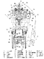
図面は容器の一例である上面側を開口した箱体内部に袋体を敷設する作業に用いられる袋敷設装置を示し、図1及び図2に於いて、この袋敷設装置1は、ロール状に巻回した筒状のフィルム原反fを、装置側部に設けた支持機構2により支持し、支持機構2から引出したフィルム原反fを、装置上部の分離位置aに設けた分離機構3により一つの袋体Fに分離する。
【0013】
且つ、分離機構3下部に設けた袋開口機構4により袋体Fの口縁部Faを開口し、袋開口機構4下部に設けた袋被覆機構5により袋体Fの口縁部Faを開口保持して、搬送コンベア6上の装填位置bに搬送した箱体Bの開口側周縁部に被覆する。袋被覆機構5上部に設けた袋引下げ機構7によりフィルム原反fを引下げ、袋長さ調節機構8によりフィルム原反fを所定長さに弛ませる。
【0014】
上述の支持機構2は、例えば合成樹脂又は紙のような材質等を複合した透光性を有するフィルム原反fを、扁平状態(例えばガゼット折り状態、平折り状態)に折畳んだまま巻回して引出し可能に支持する。また、モータ(図示省略)により引出し量に対応して繰出し方向に回転したり、巻取り方向に回転してもよい。
【0015】
フィルム原反fは、ダンサーロール11及びガイドロール12,13,14,15と、分離位置a上部に軸架した支持ロール16と押えロール17とに周回され、引出し側端部を、ローラ16,17下部に架設した繰出し板18,18の間に挿入して略垂直に引出しガイドする。また、ロール12〜17の何れか一つ又は複数を減速機付きモータ(図示省略)により送り方向に回転してもよい。
【0016】
前述の分離機構3は、図3、図4にも示すように、鋸刃状の切断刃24が出没許容される形状の受け部材25aを、繰出し板18,18下部に引出されるフィルム原反fの右側面と対向して支持枠19に取付け、切断刃24が接触回避される凹状の受け部材25bを、切断刃24と対向して支持枠20に取付けている。
【0017】
支持枠19背面に固定した進退シリンダ21は、切断刃24を、受け部材25a前面に突出する方向に前後動して、フィルム原反fを所定長さに切断する。
【0018】
一方、電源(図示省略)に接続した加熱ヘッド26を、フィルム原反fの切断部分よりも下位左側面と対向して支持枠20前面に取付け、耐熱性を有する受け部材27を、加熱ヘッド26と対向して支持枠19に取付けている。
【0019】
支持枠20背面に固定した進退シリンダ22は、加熱ヘッド26を、フィルム原反fの切断側下部が受け部材27に対して押圧される方向に前後動して、フィルム原反fを幅方向に熱シールする。また、切断刃24に代わる他の切断手段として、例えばカッタや回転刃等の刃を幅方向に移動させて切断してもよい。
【0020】
且つ、剥離部材28を、フィルム原反fの切断部分よりも上位側面と対向して支持枠19,20に取付け、移動シリンダ(図示省略)によりフィルム原反fの開口側縁部に沿って相反する方向に相対移動して、フィルム原反fの切断部分に近い部分を接触抵抗により幅方向に変位させ、フィルム原反fの開口側対向縁部を剥離する。
【0021】
また、剥離部材28を、後述する負圧発生手段(図示省略)に接続して、フィルム原反fの対向縁部を負圧により剥離してもよい。
【0022】
上述の支持枠19端部は、分離機構3の両側部に軸架したガイド軸29に対して前後移動可能に係合され、支持枠20の端部を、ガイド軸29の一端側に固定し、支持枠30の端部を、ガイド軸29の他端側を固定している。
【0023】
且つ、支持枠19の後方側枠部35に鉛直軸受した支持軸31と、支持枠19,30との間を、アーム32とリンク33とで連結して、枠部35に固定した進退シリンダ34により支持枠19を前後移動させ、支持枠19,20を、フィルム原反fと対向する方向に相対移動する。
【0024】
前述の袋長さ調節機構8は、高さ検知センサ(図示省略)による検知に基づいて駆動され、図5にも示すように、ロール36,36を、分離機構3下部に引出されるフィルム原反fの左側面と対向して支持枠38に取付け、ロール36の間に挿入されるロール37を、支持枠39に取付けている。
【0025】
且つ、支持枠38,39を、枠部35下面に取付けたガイド軸29と、支持枠30と、支持軸31と、アーム32と、リンク33とでフィルム原反fと対向する方向に相対移動して、袋引下げ機構7により引下げられたフィルム原反fをロール36,37により蛇行する状態に押圧して、フィルム原反fを、箱体Bのサイズに対応して所定長さに弛みを持たせる。
【0026】
前述の袋開口機構4は、図6にも示すように、吸着子40を、袋引下げ機構7により下限位置に引下げられたフィルム原反fの開口側両縁部と対向して支持枠41前面に取付け、相対向する吸着子40を幅方向に変位させて取付けると共に、例えばコイルスプリングや合成ゴム等の弾性体によりフィルム原反fに対して押圧される方向に付勢している。
【0027】
一方、側面から見て略L字状の挾持板42を、吸着子40と対向して支持枠41下面に取付けると共に、支持枠41端部に取付けた挾持シリンダ43により、吸着子40の吸着面に対してフィルム原反f又は袋体Fの開口側縁部を押圧する閉角度と、その押圧が解除される開角度とに回動する。
【0028】
且つ、支持枠41上端に固定した支軸44両端部を、分離機構3の両側部に交差して軸支した支持アーム45,45の下端部に固定し、支持アーム45,45の上端部を、分離機構3上部に軸架した支軸46,46の端部に固定して、支軸46,46の端部に固定したギャ47,47を互い歯合している。
【0029】
一方の支持アーム45下端部に連結したクランク棒48を、右側上部に軸支した回転板49の円周上に連結して、回転板49の回転により、支持アーム45,45を、左右の吸着子40がフィルム原反f又は袋体Fの開口側縁部に対して押圧される閉角度と、吸着子40で保持した袋体Fの開口側縁部が箱体Bの開口側周縁部に対して被覆可能な大きさに開口される開角度とに回動する。
【0030】
上述の吸着子40は、例えば吸気ブロワや真空ポンプ等の負圧発生手段(図示省略)に接続され、フィルム原反fの開口側縁部に対して押圧したとき、その吸着面に生じる負圧によりフィルム原反fの開口側縁部を吸着保持する。
【0031】
前述の袋引下げ機構7は、例えば合成ゴムや軟質樹脂等の接触抵抗の大きい部材を装着又は歯面や凹凸等を挾持面側に形成した一対のチャック7aを、フィルム原反fの両側縁部と対向して、搬送コンベア6を跨ぐ状態に架設した昇降枠50の短手側支持枠50aに取付け、支持枠50aに取付けた挾持シリンダ7bにより、チャック7a,7aを、フィルム原反fの両側縁部が挾持される閉角度と、その挾持が解除される開角度とに回動する。
【0032】
且つ、袋引下げ機構7の下部には、気体供給源(例えばコンプレッサーや送風ブロワー等)に接続した噴射ノズル51を、後述する袋保持体52で保持される袋体F底部に向けて取付けている。また、気体供給源から供給される気体を袋体Fに直接吹付けてもよい。その気体に代わる他の物として、例えばアルコールやエタノール等の蒸発気化するような液体又は液化気体を用いてもよい。
【0033】
前述の袋被覆機構5は、図7にも示すように、袋保持体52を、上述の吸着子40で開口するフィルム原反f又は袋体Fの開口側内縁部と対向して昇降枠50の長手側縁部に取付け、板状又は棒状に形成した袋保持体52の基端部を、搬送コンベア6と平行して昇降枠50の長手側縁部に取付けたロータリ式の保持シリンダ53に直結して、吸着子40により開口したフィルム原反f又は袋体Fの開口側内縁部が緊張状態に保持される略鉛直姿勢と、その保持が解除される略水平姿勢とに回動(略90度)する。
【0034】
且つ、保持シリンダ53の側部に取付けた回動シリンダ54は、保持シリンダ53全体を、吸着子40により開口したフィルム原反f又は袋体Fの開口縁部に対して袋保持体52が挿入される角度(又は開口縁部が緊張される斜め外向き角度)と、その挿入が回避される斜め下向き角度とに回動する。
【0035】
一方、昇降枠50の四隅部を、搬送コンベア6の両側部に立設したガイド軸55に対して上下移動可能に取付け、昇降枠50の両側端部に連結したクランク棒56を、搬送コンベア6の下部両側に軸支した回転板57の円周上に連結して、回転板57の回転により昇降枠50全体を上下動させ、袋引下げ機構7のチャック7aを、繰出し板18,18下部に引出したフィルム原反fの両側縁部が挾持される上限位置と、チャック7aで挾持したフィルム原反fの開口側両縁部が吸着子40により吸着される下限位置とに上下動する。
【0036】
且つ、袋被覆機構5の袋保持体52を、吸着子40により開口した袋体Fの開口側内縁部に対して挿入される上限位置と、袋保持体52で保持した袋体Fの口縁部Faが搬送コンベア6上の装填位置bに搬送された箱体Bの開口側縁部に被覆される下限位置とに上下動する。また、クランク棒48,56及び回転板49,57に代わる他の昇降手段として、例えばエアシリンダやソレノイド、チェーン、カム等を用いてもよい。
【0037】
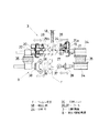
前述の搬送コンベア6は、図2にも示すように、送りチェーン58を、始端部及び終端部に軸支したスプロケット59の間に張架し、送り部材60(例えばアタッチメント)を、送りチェーン58全長に対して一個ずつ箱体Bが積載される間隔に隔てて取付け、送りチェーン58の両側部に、送りローラ61…を搬送方向に対して所定間隔に隔てて配列している。
【0038】
且つ、始端側下部に配設した減速機付きモータ62は、スプロケット63,64,65,66,67,68と、チェーン69,70,71と、変速機72とを介して、送り部材60を搬送方向に周回移動させ、送りチェーン58上に積載された箱体Bを装填位置bに確実搬送する。また、始端側の送りローラ61…を、モータ(図示省略)により回転駆動してもよい。
【0039】
且つ、スプロケット63の軸端部に連結したギャボックス75と、右側上部に設けたギャボックス76とを伝達軸77で連結し、ギャボックス76と回転板49とを伝達軸78で連結して、支持アーム45を連動して回動すると共に、スプロケット64,65の軸端部に固定した回転板57を回転して、昇降枠50を連動して上下動する。
【0040】
装填位置bに配設したストッパ73は、同位置下部に配設した出没シリンダ74により出没動作され、一つの箱体Bを装填位置bに一旦停止する。
【0041】
また、次の箱体Bを、出没式又は旋回式のストッパ(図示省略)により搬送コンベア6の始端部直前に一旦停止してもよい。加えて、装填位置bに停止された箱体Bを、例えばプッシャや幅寄せ板等の幅寄せ手段により基準位置に幅寄せしてもよい。
【0042】
図示実施例は上記の如く構成するものにして、以下、袋敷設装置1による袋体Fを箱体B内部に敷設する動作を説明する。
先ず、図1、図8に示すように、支持機構2から引出したフィルム原反fを、ロール16,17を介して、繰出し板18,18の間に挿入した後、袋被覆機構5の昇降枠50を上限位置に上昇して、繰出し板18下部に引出されたフィルム原反fの両側縁部を、袋引下げ機構7のチャック7a,7aで挾持する。
【0043】
次に、図9に示すように、昇降枠50を下限位置に降下して、フィルム原反fを開口可能に高さに引下げた後、袋長さ調節機構8のロール36,37によりフィルム原反fを押圧して、箱体Bのサイズに対応して弛ませ量を可変調節する。
【0044】
且つ、分離位置aに引出されたフィルム原反fの全幅を、分離機構3の切断刃24で切断し、その下位を加熱ヘッド26で熱シールして、一つの袋体Fに分離する。同時に、袋開口機構4の吸着子40…によりフィルム原反f又は袋体Fの開口側両縁部を吸着保持して、箱体Bの開口側周縁部に対して被覆可能な大きさに開口する。
【0045】
再び、昇降枠50を上昇して、吸着子40…で開口した袋体Fの口縁部Faを、略鉛直に回動した袋保持体52…により開口状態に保持する。この後、切断刃24及び加熱ヘッド26を初期位置に復帰させ、吸着子40…による吸着保持を解除する。
【0046】
一方、上面側を開口した箱体Bを、搬送コンベア6上の装填位置bに搬送停止した後、図7にも示すように、昇降枠50を下限位置に降下して、袋保持体52…で開口保持した袋体Fの口縁部Faを、箱体Bの開口側外周縁部(又はフラップ)に被覆する。
【0047】
被覆直前に於て、噴射ノズル51から吐出する気体を、袋保持体52…で保持した袋体Fの上面側に吹付け、その袋体Fを、箱体B内部に対して敷設される方向に表裏反転すると共に、箱体B内部と対応する大きさに拡張して挿入する。
【0048】
また、吸着子40又は袋保持体52で保持した袋体Fを表裏反転した後、箱体B側を上昇させて袋体Fを挿入したり、押込み部材(図示省略)により強制的に装填してもよい。
【0049】
次に、袋保持体52…を解除姿勢に回動して、箱体Bと袋体Fの間から抜取り、袋保持体52…による保持を解除した後、搬送コンベア6に載置された箱体Bを次工程(例えば袋詰工程、充填工程)に搬送する。
【0050】
上述と同様にして、昇降枠50を上限位置と下限位置とに昇降して、チャック7a,7aで挾持したフィルム原反f又は袋体Fを引下げる動作と、袋保持体52…で開口保持した袋体Fの口縁部Faを箱体Bに被覆する動作とを一回の昇降動作により略同時に行う。且つ、次の箱体Bを装填位置bに搬送して、袋体Fを、箱体B内部に敷設する作業を継続して行う。
【0051】
以上のように、袋開口機構4に対してフィルム原反f又は袋体Fを供給する動作と、袋開口機構4により開口した袋体Fの口縁部Faを箱体Bの開口側周縁部に被覆する動作とを略同時に行うので、袋体Fを敷設するときに要する時間が大幅に短縮され、装置全体の動作及び時間に無駄がなく、敷設作業が能率的に行えると共に、処理能力の向上を図ることができる。
【0052】
しかも、昇降枠50を上限位置と下限位置とに昇降して、先に引出された袋体Fを袋被覆機構5で開口保持して箱体Bに被覆するとき、次に被覆されるフィルム原反f又は袋体Fを袋引出し機構7により予め引出し準備しておくので、次の袋体Fを開口及び被覆する作業に即移行することができ、作業能率が向上する。
【0053】
さらに、分離機構3を独立駆動して、袋開口機構4に供給されるフィルム原反fを一つの袋体Fに分離するので、そのフィルム原反fを分離するときのタイミングを可変調節するだけで、袋体Fのサイズを自由に変更することができる。
【0054】
さらにまた、袋開口機構4と、袋被覆機構5及び袋引下げ機構7とを、モータ62と、ギャボックス75,76と、伝達軸77,78と、クランク棒48,56と、回転板49,57とで構成される一つの連動駆動機構により駆動するので、機構4,5,7に駆動手段を個々に設ける必要がなく、装置全体の構成及び構造を簡素化することができる。且つ、装置の製作が簡単且つ容易に行え、安価に製作することができる。
【0055】
この発明の構成と、上述の実施例との対応において、
この発明の容器は、実施例の箱体Bに対応し、
以下同様に、
連続袋体は、フィルム原反fに対応し、
袋繰出し部は、繰出し板18に対応し、
袋開口手段は、袋開口機構4に対応し、
袋引出し被覆手段は、袋被覆機構5(袋被覆手段)と、袋引下げ機構7(袋引下げ手段)とに対応し、
袋分離手段は、分離機構3に対応し、
連動駆動手段は、アーム45と、クランク棒48,56と、回転板49,57と、モータ62と、ギャボックス75,76と、伝達軸77,78又はチェーンやベルト、ネジ軸、カム等とに対応するも、
この発明は、上述の実施例の構成のみに限定されるものではない。
【0056】
上述の吸着子40に代わる他の開口方法として、例えばロール型の吸着子で開口したり、粘着剤や粘着テープ、チャックやアーム等により開口してもよく、さらに、所定サイズに形成した袋体Fを箱体B内部に敷設してもよい。
【0057】
また、実施例のシリンダは加圧エアー供給源に接続され、シリンダに代わる駆動手段として、例えばソレノイドやモータ等のアクチュエータを用いてもよい。
【図面の簡単な説明】
【図1】 袋敷設装置による袋体の敷設動作を示す側面図。
【図2】 フィルム原反の引出し動作及び箱体の搬送動作を示す正面図。
【図3】 分離機構による分離動作を示す側面図。
【図4】 分離機構の進退動作を示す平面図。
【図5】 袋長さ調節機構の進退動作を示す平面図。
【図6】 袋開口機構による袋体の開口動作を示す側面図。
【図7】 袋被覆機構による袋体の被覆動作を示す平面図。
【図8】 袋引下げ機構の挾持動作及び袋被覆機構の保持動作を示す側面図。
【図9】 フィルム原反の引下げ動作及び袋体の被覆動作を示す側面図。
【符号の説明】
f…フィルム原反
F…袋体
Fa…口縁部
B…箱体
1…袋敷設装置
3…分離機構
4…袋開口機構
5…袋被覆機構
6…搬送コンベア
7…袋引下げ機構
7a…チャック
8…袋長さ調節機構
18…繰出し板
24…切断刃
26…加熱ヘッド
36,37…ロール
40…吸着子
51…噴射ノズル
52…袋保持体[0001]
BACKGROUND OF THE INVENTION
The present invention relates to a bag laying apparatus used for laying a bag inside a container such as a box made of corrugated paper or cardboard, a container made of synthetic resin, metal, wood, or the like.
[0002]
[Prior art]
Conventionally, as an apparatus for laying the above-described bag body, for example, a bag body pulled out from a film roll is held by an upper nail of the bag body transport mechanism and pulled out for a predetermined length, and then the adsorber of the bag body expanding mechanism is used. The mouth of the bag body is opened by suction. The lower part of the bag body is lowered while holding the mouth part of the bag body with the lower nails to cover the opening side peripheral edge of the box body whose upper surface is opened, and the bag body is turned upside down by the air blown from the blower There is a bag laying device (Japanese Patent Laid-Open No. 11-138664) that is inserted into the box.
[0003]
[Problems to be solved by the invention]
However, the above-mentioned device orbits the upper nail of the bag body transport mechanism and the lower nail of the bag body lowering mechanism to cover and lay the bag body on the box body. It is difficult to match the circulation timing, and if the rotation speed of the upper and lower claws is increased, a holding error is likely to occur, so that there is a limit to the laying capacity of the bag body.
[0004]
In addition, after the bag body held by the upper nail is moved to a fixed position, the bag body is held by the lower nail and covers the opening side peripheral portion of the box body, so that the upper nail and the lower nail return to the predetermined position. Until it moves, it cannot immediately shift to the work of opening the next bag, and the work efficiency is poor. In addition, since the mechanism for interlocking the bag body transport mechanism and the bag body lowering mechanism is complicated, there is a problem that it takes time and labor to manufacture the apparatus.
[0005]
The present invention has been made in view of the above problems, the operation of lowering the bag feeding portion bag to be subsequently covered by a bag pulled means, bag drawn previously held by the bag opening means that by the bag covering means Of the bag laying device that can reduce the time required for laying the bag body and improve the work efficiency and the processing capacity by performing the operation of covering the peripheral edge of the opening side of the container substantially simultaneously. For the purpose of provision.
[0006]
[Means for Solving the Problems]
The invention according to
[0007]
The invention according to
[0008]
The invention described in
[0009]
[Action and effect]
According to the first aspect of the invention, the operation of lowering the bag feeding portion bag to be subsequently covered by the bag pulled means for supplying a bag against the bag opening means, bag opening means that by the bag covering means The operation of covering the opening side peripheral portion of the container held by the previously held bag body at substantially the same time is performed substantially simultaneously, so that the time required for laying the bag body is greatly reduced, and the operation of the entire apparatus and There is no waste of time, laying work can be performed efficiently, and processing capacity can be improved. In addition, when the bag body previously pulled out by the bag covering means is held open to cover the container, the bag body to be covered next by the bag lowering means is prepared in advance so that the next bag body can be The work can be immediately shifted to the opening and covering work, and the work efficiency is improved.
[0010]
According to the second aspect of the present invention, the bag separating means is independently driven to separate the continuous bag body supplied to the bag opening means into one bag body, so that the timing when separating the continuous bag body is variable. The size of the bag can be freely changed simply by adjusting.
[0011]
According to the third aspect of the present invention, the bag opening means and the bag withdrawal covering means are driven by a single interlocking drive mechanism, so that it is not necessary to provide the drive means individually, and the configuration and structure of the entire apparatus are simplified. be able to. In addition, the apparatus can be manufactured easily and easily, and can be manufactured at low cost.
[0012]
【Example】
An embodiment of the present invention will be described below in detail with reference to the drawings.
The drawings show a bag laying device used for laying a bag body inside a box body having an upper surface opened as an example of a container. In FIGS. 1 and 2, the
[0013]
Further, the opening edge Fa of the bag body F is opened by the
[0014]
The above-described
[0015]
The original film f is circulated by the dancer roll 11 and the guide rolls 12, 13, 14, 15 and the
[0016]
As shown in FIGS. 3 and 4, the
[0017]
The advancing / retracting
[0018]
On the other hand, the
[0019]
The advancing / retreating
[0020]
In addition, the peeling
[0021]
Further, the peeling
[0022]
The above-mentioned end portion of the
[0023]
Further, the
[0024]
The above-described bag
[0025]
In addition, the support frames 38 and 39 are relatively moved in a direction facing the original film f by the
[0026]
As shown in FIG. 6, the
[0027]
On the other hand, a substantially L-shaped
[0028]
In addition, both ends of the support shaft 44 fixed to the upper end of the
[0029]
A
[0030]
The
[0031]
The above-described
[0032]
In addition, an
[0033]
As shown in FIG. 7, the
[0034]
Further, the
[0035]
On the other hand, the four corners of the lifting
[0036]
In addition, the upper limit position at which the
[0037]
As shown in FIG. 2, the above-described
[0038]
Further, the
[0039]
In addition, the
[0040]
The
[0041]
Further, the next box B may be temporarily stopped immediately before the start end portion of the
[0042]
The illustrated embodiment is configured as described above, and the operation of laying the bag F by the
First, as shown in FIGS. 1 and 8, the original film f drawn from the
[0043]
Next, as shown in FIG. 9, the elevating
[0044]
In addition, the entire width of the original film f pulled out to the separation position a is cut by the
[0045]
The elevating
[0046]
On the other hand, after the box B having the upper surface opened is stopped at the loading position b on the
[0047]
Immediately before coating, the gas discharged from the
[0048]
Further, after the bag body F held by the
[0049]
Next, the
[0050]
In the same manner as described above, the lifting
[0051]
As described above, the operation of supplying the film original fabric f or the bag body F to the
[0052]
In addition, when the elevating
[0053]
Furthermore, the
[0054]
Furthermore, the
[0055]
In the correspondence between the configuration of the present invention and the above-described embodiment,
The container of the present invention corresponds to the box B of the embodiment,
Similarly,
The continuous bag corresponds to the original film f,
The bag feeding portion corresponds to the
The bag opening means corresponds to the
The bag withdrawal covering means corresponds to the bag covering mechanism 5 (bag covering means) and the bag pulling mechanism 7 (bag pulling means),
The bag separating means corresponds to the
The interlock driving means includes an
The present invention is not limited to the configuration of the above-described embodiment.
[0056]
As another opening method instead of the above-described
[0057]
Further, the cylinder of the embodiment may be connected to a pressurized air supply source, and an actuator such as a solenoid or a motor may be used as a driving means instead of the cylinder.
[Brief description of the drawings]
FIG. 1 is a side view showing a bag laying operation by a bag laying device.
FIG. 2 is a front view showing a film original drawing operation and a box conveying operation.
FIG. 3 is a side view showing a separation operation by a separation mechanism.
FIG. 4 is a plan view showing an advance / retreat operation of the separation mechanism.
FIG. 5 is a plan view showing the advance / retreat operation of the bag length adjusting mechanism.
FIG. 6 is a side view showing the opening operation of the bag body by the bag opening mechanism.
FIG. 7 is a plan view showing the covering operation of the bag body by the bag covering mechanism.
FIG. 8 is a side view showing the holding operation of the bag pulling mechanism and the holding operation of the bag covering mechanism.
FIG. 9 is a side view showing a film original fabric lowering operation and a bag covering operation.
[Explanation of symbols]
f ... Original film F ... Bag body Fa ... Mouth edge B ...
Claims (3)
上記袋体を、該袋体が繰出される袋繰出し部から引下げる袋引下げ手段と、
上記袋引下げ手段により引下げられて供給される袋体を保持し、容器の開口側周縁部に対して被覆可能な大きさに開口する袋開口手段と、
上記袋開口手段により開口した袋体の口縁部を保持して容器の開口側周縁部に被覆する袋被覆手段を備えるとともに、
上記袋引下げ手段と袋被覆手段とを備える袋引出し被覆手段として、上記袋被覆手段と、該袋被覆手段の上部に袋引下げ手段とを取付けて一体的に設けた昇降枠と、該昇降枠の昇降手段を備え、
上記昇降枠を上限位置と下限位置とに昇降して、袋引下げ手段により次に被覆される袋体を袋繰出し部から引下げる動作と、袋被覆手段による袋開口手段により保持されている先に引出された袋体を容器の開口側周縁部に被覆する動作とを一回の昇降動作により略同時に行うことを特徴とする
袋敷設装置。A bag laying device that covers the opening edge of the bag body on the peripheral edge of the opening of the container and lays the bottom of the bag body in a state of being accommodated inside the container,
A bag pulling means for pulling down the bag body from a bag feeding portion through which the bag body is drawn;
A bag opening means for holding the bag body supplied by being pulled down by the bag pulling means, and opening to a size capable of covering the peripheral edge of the opening side of the container;
While having a bag covering means for holding the mouth edge portion of the bag body opened by the bag opening means and covering the opening side peripheral edge portion of the container,
As the bag drawer covering means comprising the bag pulling means and the bag covering means, the bag covering means, a lifting frame integrally provided with a bag pulling means attached to the top of the bag covering means, With lifting means,
By lifting the lifting frame to the upper limit position and lower limit position, then the operation of lowering the bag feeding portion bag to be coated, is held by the bag opening means that by the bag covering means by bag cuts means A bag laying device characterized in that the operation of covering the opening-side periphery of the container with the previously drawn bag body is performed substantially simultaneously by a single lifting operation.
請求項1記載の袋敷設装置。The bag laying apparatus according to claim 1, further comprising a bag separating means for separating the continuous bag body supplied to the bag opening means into a size substantially corresponding to the size of the container, upstream of the bag opening means.
請求項1又は2記載の袋敷設装置。The bag laying apparatus according to claim 1 or 2, further comprising interlocking drive means for driving the bag opening means and the bag withdrawal covering means in conjunction with each other.
Priority Applications (1)
| Application Number | Priority Date | Filing Date | Title |
|---|---|---|---|
| JP2000115257A JP4043689B2 (en) | 2000-04-17 | 2000-04-17 | Bag laying device |
Applications Claiming Priority (1)
| Application Number | Priority Date | Filing Date | Title |
|---|---|---|---|
| JP2000115257A JP4043689B2 (en) | 2000-04-17 | 2000-04-17 | Bag laying device |
Publications (2)
| Publication Number | Publication Date |
|---|---|
| JP2001293796A JP2001293796A (en) | 2001-10-23 |
| JP4043689B2 true JP4043689B2 (en) | 2008-02-06 |
Family
ID=18626940
Family Applications (1)
| Application Number | Title | Priority Date | Filing Date |
|---|---|---|---|
| JP2000115257A Expired - Fee Related JP4043689B2 (en) | 2000-04-17 | 2000-04-17 | Bag laying device |
Country Status (1)
| Country | Link |
|---|---|
| JP (1) | JP4043689B2 (en) |
Cited By (5)
| Publication number | Priority date | Publication date | Assignee | Title |
|---|---|---|---|---|
| CN102849451A (en) * | 2012-04-23 | 2013-01-02 | 常熟三禾精工科技有限公司 | Swing type bag-holding conveying mechanical hand |
| CN102849453A (en) * | 2012-04-23 | 2013-01-02 | 常熟三禾精工科技有限公司 | Swing type bag-holding conveying mechanical hand |
| CN103448952A (en) * | 2013-08-06 | 2013-12-18 | 宋小雷 | Bag elevator |
| CN103991581A (en) * | 2014-05-30 | 2014-08-20 | 苏州优备精密电子有限公司 | Expanding device for paper bag opening |
| CN104648719A (en) * | 2015-01-31 | 2015-05-27 | 瑞安市智科包装机械有限公司 | Zipper bag opening device |
Families Citing this family (7)
| Publication number | Priority date | Publication date | Assignee | Title |
|---|---|---|---|---|
| CN201712829U (en) * | 2009-12-31 | 2011-01-19 | 深圳安吉尔饮水产业集团有限公司 | Static eliminating bag pre-opening device |
| CN102114921B (en) * | 2009-12-31 | 2012-12-05 | 深圳安吉尔饮水产业集团有限公司 | Liquid product bagging machine |
| CN102673833B (en) * | 2012-05-17 | 2014-01-08 | 江苏牧羊集团有限公司 | Automatic bagging mechanism |
| CN109398822B (en) * | 2018-12-29 | 2024-01-09 | 青岛同晋自动化科技有限公司 | Automatic tank opening machine |
| CN110422391B (en) * | 2019-08-23 | 2024-02-13 | 安徽永成电子机械技术有限公司 | Material bag bagging mechanism |
| CN111545407B (en) * | 2020-05-19 | 2021-06-22 | 威海劲变信息科技有限公司 | Production equipment of sandwich type structure insulation board |
| CN115057047B (en) * | 2022-08-03 | 2023-12-12 | 重庆文理学院 | Tea baling press and tealeaves picking robot thereof |
-
2000
- 2000-04-17 JP JP2000115257A patent/JP4043689B2/en not_active Expired - Fee Related
Cited By (7)
| Publication number | Priority date | Publication date | Assignee | Title |
|---|---|---|---|---|
| CN102849451A (en) * | 2012-04-23 | 2013-01-02 | 常熟三禾精工科技有限公司 | Swing type bag-holding conveying mechanical hand |
| CN102849453A (en) * | 2012-04-23 | 2013-01-02 | 常熟三禾精工科技有限公司 | Swing type bag-holding conveying mechanical hand |
| CN102849451B (en) * | 2012-04-23 | 2014-06-18 | 常熟三禾精工科技有限公司 | Swing type bag-holding conveying mechanical hand |
| CN102849453B (en) * | 2012-04-23 | 2014-06-18 | 常熟三禾精工科技有限公司 | Swing type bag-holding conveying mechanical hand |
| CN103448952A (en) * | 2013-08-06 | 2013-12-18 | 宋小雷 | Bag elevator |
| CN103991581A (en) * | 2014-05-30 | 2014-08-20 | 苏州优备精密电子有限公司 | Expanding device for paper bag opening |
| CN104648719A (en) * | 2015-01-31 | 2015-05-27 | 瑞安市智科包装机械有限公司 | Zipper bag opening device |
Also Published As
| Publication number | Publication date |
|---|---|
| JP2001293796A (en) | 2001-10-23 |
Similar Documents
| Publication | Publication Date | Title |
|---|---|---|
| JP4043689B2 (en) | Bag laying device | |
| JP5918942B2 (en) | Rotary packaging machine | |
| JPH06211210A (en) | Device for applying strip material to package of parallelepiped | |
| JP2006069630A (en) | Inner bag machine | |
| JP3543849B2 (en) | Bag opening device | |
| JP4644350B2 (en) | Folding box take-out supply device | |
| JP2620209B2 (en) | Equipment for automatic packaging of goods | |
| JP4136290B2 (en) | Bag laying device | |
| JP2003112709A (en) | Bag laying equipment | |
| JP3954768B2 (en) | Bag laying device | |
| JPH11292025A (en) | Suction conveyer, and method and machine for packaging using the same | |
| JP2607730Y2 (en) | Bag laying equipment | |
| JP2594444Y2 (en) | Bag laying equipment | |
| JP4136553B2 (en) | Bag laying device | |
| JP3701711B2 (en) | Bag laying device | |
| JPH08151019A (en) | Bag opening device | |
| JP2599007Y2 (en) | Bag laying equipment | |
| JP3913818B2 (en) | Bag laying device | |
| JPH10114316A (en) | Push-in type bag laying device | |
| JPH0754092Y2 (en) | Bag laying equipment | |
| JP2600935Y2 (en) | Bag laying equipment | |
| JP2004074569A (en) | Bag laying apparatus | |
| JPH1053221A (en) | Bag fold-in type laying device | |
| JP2000062051A (en) | Packaging body laying apparatus | |
| JPH06255628A (en) | Device for placing bag |
Legal Events
| Date | Code | Title | Description |
|---|---|---|---|
| A621 | Written request for application examination |
Free format text: JAPANESE INTERMEDIATE CODE: A621 Effective date: 20050124 |
|
| A977 | Report on retrieval |
Free format text: JAPANESE INTERMEDIATE CODE: A971007 Effective date: 20070510 |
|
| A131 | Notification of reasons for refusal |
Free format text: JAPANESE INTERMEDIATE CODE: A131 Effective date: 20070515 |
|
| A521 | Written amendment |
Free format text: JAPANESE INTERMEDIATE CODE: A523 Effective date: 20070717 |
|
| A131 | Notification of reasons for refusal |
Free format text: JAPANESE INTERMEDIATE CODE: A131 Effective date: 20070828 |
|
| A521 | Written amendment |
Free format text: JAPANESE INTERMEDIATE CODE: A523 Effective date: 20071019 |
|
| TRDD | Decision of grant or rejection written | ||
| A01 | Written decision to grant a patent or to grant a registration (utility model) |
Free format text: JAPANESE INTERMEDIATE CODE: A01 Effective date: 20071113 |
|
| A61 | First payment of annual fees (during grant procedure) |
Free format text: JAPANESE INTERMEDIATE CODE: A61 Effective date: 20071114 |
|
| R150 | Certificate of patent or registration of utility model |
Free format text: JAPANESE INTERMEDIATE CODE: R150 Ref document number: 4043689 Country of ref document: JP Free format text: JAPANESE INTERMEDIATE CODE: R150 |
|
| FPAY | Renewal fee payment (event date is renewal date of database) |
Free format text: PAYMENT UNTIL: 20101122 Year of fee payment: 3 |
|
| FPAY | Renewal fee payment (event date is renewal date of database) |
Free format text: PAYMENT UNTIL: 20111122 Year of fee payment: 4 |
|
| FPAY | Renewal fee payment (event date is renewal date of database) |
Free format text: PAYMENT UNTIL: 20111122 Year of fee payment: 4 |
|
| FPAY | Renewal fee payment (event date is renewal date of database) |
Free format text: PAYMENT UNTIL: 20121122 Year of fee payment: 5 |
|
| FPAY | Renewal fee payment (event date is renewal date of database) |
Free format text: PAYMENT UNTIL: 20131122 Year of fee payment: 6 |
|
| LAPS | Cancellation because of no payment of annual fees |