JP4133696B2 - Pushbutton switch structure - Google Patents
Pushbutton switch structure Download PDFInfo
- Publication number
- JP4133696B2 JP4133696B2 JP2003310629A JP2003310629A JP4133696B2 JP 4133696 B2 JP4133696 B2 JP 4133696B2 JP 2003310629 A JP2003310629 A JP 2003310629A JP 2003310629 A JP2003310629 A JP 2003310629A JP 4133696 B2 JP4133696 B2 JP 4133696B2
- Authority
- JP
- Japan
- Prior art keywords
- button
- switch
- bottom cap
- movable contact
- contact
- Prior art date
- Legal status (The legal status is an assumption and is not a legal conclusion. Google has not performed a legal analysis and makes no representation as to the accuracy of the status listed.)
- Expired - Fee Related
Links
Images


Description
本発明は、押ボタンスイッチ構造に関するものである。 The present invention relates to a pushbutton switch structure.
押ボタンスイッチは、ボタン部を押すことで操作を行うもので、一般的に、ボタン本体を有する操作機構と、接点部を有するコンタクト機構とからなり、例えば、自動車の自動変速機のシフトレバーに用いられる。 A push button switch is operated by pressing a button part, and generally comprises an operation mechanism having a button body and a contact mechanism having a contact part. For example, a push button switch is used as a shift lever of an automatic transmission of an automobile. Used.
従来の押ボタンスイッチ構造として、プッシュロックスイッチが知られている(例えば、特許文献1参照。)。
図10は、特許文献1の図1の再掲図である。
特許文献1のプッシュロックスイッチは、ケース1にスライド可能に嵌めた操作子3を移動させることで、可動盤5が移動して可動接片8を固定接点9に接触させる。
ケース1は、断面形状が略コ字形状で、開口側に基盤2を取り付けた構成である。
可動接片8は、可動盤5に嵌合するとともに、基盤2内面を弾性を有して摺接し、固定接点9と接離する。
FIG. 10 is a reproduction of FIG.
In the push lock switch of Patent Document 1, the
The case 1 has a substantially U-shaped cross-sectional shape and a base 2 attached to the opening side.
The
しかし、特許文献1のプッシュロックスイッチは、ケース1の横(図の左右)の開口側に基盤2を取り付けた構成であり、使用条件によっては、横の開口を底(図の下方)の開口に変えた仕様にしたいことがある。例えば、基盤2側への押し付け力が大きい場合、ケース1の横を一体に成形し、底の開口にボトムキャップを嵌めると、簡単な構成で剛性を確保しやすい。ただ、ボトムキャップを嵌める構造では、ボトムキャップを嵌める際に、ボトムキャップが可動接片8の先端に干渉することがあり、その点では、従来の横から可動接片8に抗して基盤2などの蓋材を嵌める構成が有利であった。
However, the push lock switch of Patent Document 1 has a configuration in which the base 2 is attached to the side of the case 1 on the side (left and right in the figure). There are times when I want to change the specifications. For example, when the pressing force to the base 2 side is large, if the side of the case 1 is integrally formed and a bottom cap is fitted into the bottom opening, it is easy to ensure rigidity with a simple configuration. However, in the structure in which the bottom cap is fitted, when the bottom cap is fitted, the bottom cap may interfere with the tip of the
本発明は、スイッチケースにボトムキャップを取り付ける際に、ボトムキャップと可動接触子との干渉を防止し、押ボタンスイッチの組立てを容易にすることを課題とする。 An object of the present invention is to prevent interference between the bottom cap and the movable contact when the bottom cap is attached to the switch case, and to facilitate the assembly of the push button switch.
請求項1に係る発明は、スイッチケースと、このスイッチケースに押込み動可能に設けるとともに可動接触子を備えるボタン部と、このボタン部の可動接触子に対応する固定接触子を備えスイッチケースのボトム部に取り付けるボトムキャップとを有する押ボタンスイッチ構造において、ボタン部のボトムキャップ側に、可動接触子の拡がりを規制するストッパ面と、ボトムキャップのボタン部側に、このボトムキャップをスイッチケースに取り付ける際、スイッチケースと可動接触子の端との間に押し込まれて、ストッパ面で規制された可動接触子の端をスイッチの中央に導く傾斜ガイド面と、ボタン部を待機位置に戻す復帰スプリングと、復帰スプリングとは別に設けられ、ボタン部の操作時にクリック感を付与するクリック片と、を備え、クリック片は、ボタン部に設けられ、ボトムキャップに設けられるクリック凸部に掛合することでボタン部の操作時にクリック感を付与することを特徴とする。
請求項2は、可動接触子と、クリック片とがボタン部に一体的、且つボタン部を中心軸とした円周上に別々に設けられ、復帰スプリングは、圧縮コイルばねであり、ボタン部の中心軸と同心に配置されていることを特徴とする。
請求項3では、固定接触子は、ボトムキャップの側面と下面に面一となるL字形状であり、可動接触子は、ボタン部を押圧した場合に、端を含む接点部側がL字形状の固定接触子の側面と下面との両方に接触することを特徴とする。
The invention according to claim 1 includes a switch case, a button portion that is provided so as to be able to be pushed into the switch case and includes a movable contact, and a fixed contact corresponding to the movable contact of the button portion. In a pushbutton switch structure having a bottom cap attached to the part, the bottom cap is attached to the switch case on the bottom cap side of the button part, a stopper surface for restricting the expansion of the movable contact, and the button part side of the bottom cap. An inclined guide surface that is pushed between the switch case and the end of the movable contact to guide the end of the movable contact restricted by the stopper surface to the center of the switch, and a return spring that returns the button portion to the standby position, A click piece that is provided separately from the return spring and that gives a click feeling when the button is operated. , Click pieces are provided on the button section, and wherein the applying click feeling when operating the button portion by engaging the click convex portion provided on the bottom cap.
According to a second aspect of the present invention, the movable contact and the click piece are provided integrally with the button portion and separately provided on the circumference with the button portion as a central axis, the return spring is a compression coil spring, It is arranged concentrically with the central axis.
According to a third aspect of the present invention , the fixed contact has an L shape that is flush with the side surface and the lower surface of the bottom cap, and the movable contact has an L shape on the contact portion side including the end when the button portion is pressed. It is characterized by contacting both the side surface and the lower surface of the fixed contact.
請求項1に係る発明では、ボタン部のボトムキャップ側に、可動接触子の拡がりを規制するストッパ面を備え、ボトムキャップのボタン部側に、このボトムキャップをスイッチケースに取り付ける際、ストッパ面で規制された可動接触子の端をスイッチの中央に導く傾斜ガイド面を備えたので、ボトムキャップをほぼ半部、押し込むと、傾斜ガイド面が可動接触子の端に当たり、傾斜ガイド面は、自身の傾斜で可動接触子の端をスイッチの中央に移動させる。移動する可動接触子は、傾斜ガイド面から離れてたわむ。従って、ボトムキャップと可動接触子との干渉を防止するという利点があるとともに、押ボタンスイッチの組立ては容易になるという利点がある。
また、ボタン部を待機位置に戻す復帰スプリングを備えているので、ボタン本体から手を離すと、復帰スプリングによって、ボタン本体を自動的に待機位置に戻すことができる。そして、復帰スプリングとは別に設けられ、ボタン部の操作時にクリック感を付与するクリック片を備えているので、押ボタンスイッチを押すと、クリック片はボトムキャップに掛合し、クリック感を付与することができる。その結果、押ボタンスイッチを押す感触とクリック感の感触とを各々設定することができる。
請求項1では、クリック片は、ボタン部に設けられ、ボトムキャップに設けられるクリック凸部に掛合することでボタン部の操作時にクリック感を付与するので、ボトムキャップにクリック凸部を設けるだけでよい。
請求項2では、可動接触子と、クリック片とがボタン部に一体的、且つボタン部を中心軸とした円周上に別々に設けられ、復帰スプリングは、圧縮コイルばねであり、ボタン部の中心軸と同心に配置されているので、押ボタンスイッチを小型化することができる。
請求項3では、固定接触子は、ボトムキャップの側面と下面に面一となるL字形状であり、可動接触子は、ボタン部を押圧した場合に、端を含む接点部側がL字形状の固定接触子の側面と下面との両方に接触するので、側面と下面との両方に接触することができる。
In the invention according to claim 1, the bottom cap side of the button part is provided with a stopper surface that restricts the expansion of the movable contact, and when the bottom cap is attached to the switch case on the button part side of the bottom cap, Because it has an inclined guide surface that guides the end of the regulated movable contact to the center of the switch, when the bottom cap is pushed almost half way, the inclined guide surface hits the end of the movable contact, and the inclined guide surface The end of the movable contact is moved to the center of the switch by tilting. The moving movable contact bends away from the inclined guide surface. Thus, with the advantage that that abolish proof interference between the bottom cap and the movable contact, there is an advantage that the assembly of the push button switch is facilitated.
Further, since the return spring for returning the button portion to the standby position is provided, the button main body can be automatically returned to the standby position by the return spring when the hand is released from the button main body. And it is provided separately from the return spring, and it has a click piece that gives a click feeling when operating the button part, so when the push button switch is pressed, the click piece engages with the bottom cap and gives a click feeling. Can do. As a result, it is possible to set the feeling of pressing the pushbutton switch and the feeling of clicking.
In claim 1 , since the click piece is provided on the button portion and is engaged with the click convex portion provided on the bottom cap to give a click feeling at the time of operation of the button portion, only the click convex portion is provided on the bottom cap. Good.
According to a second aspect of the present invention , the movable contact and the click piece are provided integrally with the button portion and separately on the circumference with the button portion as the central axis, the return spring is a compression coil spring, Since it is arranged concentrically with the central axis, the push button switch can be miniaturized.
According to a third aspect of the present invention , the fixed contact has an L shape that is flush with the side surface and the lower surface of the bottom cap, and the movable contact has an L shape on the contact portion side including the end when the button portion is pressed. Since it contacts both the side surface and the lower surface of the fixed contact, it can contact both the side surface and the lower surface.
本発明を実施するための最良の形態を添付図に基づいて以下に説明する。なお、図面は符号の向きに見るものとする。
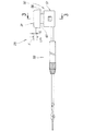
図1は、本発明の押ボタンスイッチを用いたシフトレバー構造及び車両室内を示す図であり、車両11は、オートマチック・トランスミッション車(AT車)、つまり、自動変速機を搭載した車両で、右に設けた運転席12と、この運転席12の前方に設けたインストルメントパネル13と、ステアリングホイール14と、インストルメントパネル13の中央に配置したシフトレバー装置15と、を備える。
The best mode for carrying out the present invention will be described below with reference to the accompanying drawings. The drawings are viewed in the direction of the reference numerals.
FIG. 1 is a diagram showing a shift lever structure using a pushbutton switch of the present invention and a vehicle interior. A
シフトレバー装置15は、予め決められた走行条件から所望の走行条件を選択し、設定するもので、走行条件をそれぞれ「P」、「R」、「N」、「D」、「2」の略語で表示するとともに、これらをこの順に並べた5ポジションとし、ゲート21を一直線に形成し、シフトレバー22のグリップ23を左手で握り、走行条件を表示したポジションへシフトレバー22をゲート21に沿って一直線に移動させる。その際、条件によってはノブ24を押しながら、移動させる。図1は「N」レンジを選択したシフトレバー22の状態を示す。25は押ボタンスイッチ、26はロック解除キー穴を示す。
The
Pは、パーキングレンジで、駐車専用のブレーキのレンジである。
Rは、リバース(後退)レンジで、バックギアで走行するレンジである。
Nは、ニュートラル(中立)レンジで、エンジンと駆動系との間で動力を切るレンジである。
Dは、ドライブレンジで、通常走行時、全ギアの自動変速を行うレンジである。
2は、セカンドレンジで、セカンドギアホールドで走行するレンジである。
P is a parking range, which is a parking-only brake range.
R is a reverse (reverse) range and a range in which the vehicle travels in the back gear.
N is a neutral (neutral) range in which the power is turned off between the engine and the drive train.
D is a drive range which performs automatic gear shifting of all gears during normal driving.
Reference numeral 2 denotes a second range which travels with the second gear hold.
図2は、本発明の押ボタンスイッチの正面図である。
押ボタンスイッチ25は、オーバードライブ(OD)ボタンとして用いたもので、円形のボタン部31と、このボタン部31を支持するコンタクト機構32と、コンタクト機構32に接続した電線部33とからなる。Fは待機位置、Sは動作(導通)を開始するまでのストロク量、Lmは最大ストロク量を示す。
FIG. 2 is a front view of the pushbutton switch of the present invention.
The
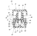
図3は、図2の3−3線断面図であり、押ボタンスイッチの待機状態を示す。
ボタン部31は、操作者が押すボタン本体34と、ボタン本体34の軸部35に嵌合してボタン本体34とともにスライドするスライダ36と、スライダ36に取り付けた可動接触子37並びにクリック片38と、からなる。
FIG. 3 is a cross-sectional view taken along line 3-3 of FIG. 2 and shows a standby state of the pushbutton switch.
The
可動接触子37は、断面U字形に成形したもので、スライダ36に固定する固定部41を形成し、固定部41に連ねてたわみ部42を距離L1だけ伸ばし、たわみ部42に連ねて接点部43を円弧状に成形したものである。44は可動接触子37の端を示す。
クリック片38は、断面U字形に成形したもので、スライダ36に固定する固定部45を形成し、固定部45に連ねてたわみ部46を距離L2だけ伸ばし、たわみ部46に連ねて凸部47を成形したもので、クリック感を付与する。
The
The
コンタクト機構32は、スイッチケース51と、スイッチケース51のボトム部52に取り付けるボトムキャップ53と、ボトムキャップ53に取り付けた図3及び図4の示されている構造で明らかな固定接触子54と、中央に設けた復帰スプリング55と、からなる。56はスイッチケース51の上部を示す。
スイッチケース51は、升形状のケース本体57の上(図の上方)にガイド筒61を成形し、底(図の下方)に開口62を成形したものである。
復帰スプリング55は、非操作時にスライダ36とともにボタン本体34を待機位置Fに戻す。
The
The
The
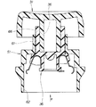
図4は、本発明の押ボタンスイッチの動作説明図であり、押ボタンスイッチの断面を示す。
押ボタンスイッチ25を最大ストロク量Lmだけ押すと、図4に示されているように可動接触子37の接点部43及び端44が固定接触子54に密着し、導通を維持する。
押ボタンスイッチ25をストロク量Sだけ押すと、可動接触子37が固定接触子54に接触し始め、互いに導通可能となる。
FIG. 4 is an operation explanatory view of the pushbutton switch of the present invention, and shows a cross section of the pushbutton switch.
When the
When the
また、押ボタンスイッチ25を最大ストロク量Lmだけ押すと、クリック片38の凸部47はボトムキャップ53のクリック凸部84に一旦掛合し、クリック感を付与する。ボタン本体34から手を離すと、復帰スプリング55によって、ボタン本体34は自動的に待機位置Fに戻る。
Further, when the
図5は、本発明の押ボタンスイッチのスライダの断面図である。
スライダ36は、可動接触子37の拡がり(矢印aの方向)を規制するストッパ面65を備える。具体的には、ボタン本体34を嵌めかつ、スイッチケース51のガイド筒61にスライド可能に嵌る筒状の嵌合部66を成形し、嵌合部66の端に可動接触子37を固定する第1固定部67を成形し、固定部67に連ねてストッパ面65を角度θ1で成形し、嵌合部66の端にクリック片38を固定する第2固定部71を成形し、第2固定部71に連ねてクリック片38の拡がり(矢印bの方向)を規制する規制面72を角度θ2で成形し、嵌合部66の端の中央にばね掛止部73を成形したものである。
つまり、ボタン部31のボトムキャップ側であるところの下部74に、可動接触子37の拡がりを規制するストッパ面65を備える。
FIG. 5 is a sectional view of the slider of the pushbutton switch of the present invention.
The
That is, the
図6は、本発明の押ボタンスイッチのボトムキャップの断面図である。
ボトムキャップ53は、傾斜ガイド面75を備える。具体的には、ボトムキャップ53は、スイッチケース51のケース本体57内に嵌合する本体76を升形状に成形し、ボトムキャップ53(本体76)のボタン部側であるところの上部77に、このボトムキャップ53をスイッチケース51に取り付ける際、ストッパ面65(図5参照)で規制された可動接触子37(図3参照)の端44(図3参照)をスイッチの中央78に導く(矢印dの方向)傾斜ガイド面75を角度θ3で形成し、ボトムキャップ53の隅81に固定接触子54をインサートし、固定接触子54に対向するボトムキャップ53の内面83にクリック凸部84を成形し、ボトムキャップ53の底中央にばね掛止部85を成形したものである。
FIG. 6 is a cross-sectional view of the bottom cap of the pushbutton switch of the present invention.
The
次に本発明の押ボタンスイッチの組立て要領及び作用を説明する。
図7は、本発明の押ボタンスイッチの組立て要領説明図(その1)である。
まず、スイッチケース51の開口62からスライダ36を入れ(矢印eの方向)、スイッチケース51のガイド筒61にスライダ36の嵌合部66を嵌めることで、スライダ36を組み込む。続けて、嵌合部66にボタン部31の軸部35を一体的に取り付ける。
Next, the assembly procedure and operation of the pushbutton switch of the present invention will be described.
FIG. 7 is an explanatory diagram (part 1) for assembling the push button switch of the present invention.
First, the
図8は、本発明の押ボタンスイッチの組立て要領説明図(その2)である。
引き続き、ボトムキャップ53のばね掛止部85に復帰スプリング55を載せ、復帰スプリング55を載せたボトムキャップ53をスイッチケース51の開口62から矢印fの如く入れ、押し込む。押し込むと、ボトムキャップ53の傾斜ガイド面75は可動接触子37に矢印gの如く当たり始める。
FIG. 8 is an explanatory diagram (part 2) for assembling the push button switch of the present invention.
Subsequently, the
図9は、本発明の押ボタンスイッチの組立て要領説明図(その3)である。
さらに押し込むことで、押ボタンスイッチの組立ては完了する。その際、ボトムキャップ53をほぼ半部、押し込むと、傾斜ガイド面75が可動接触子37の端44並びに円弧状の接点部43に当たるので、傾斜ガイド面75は、自身の傾斜で可動接触子37の端44並びに円弧状の接点部43を矢印hの如くスイッチの中央78に移動させるとともに、ストッパ面65から離れた可動接触子37の角度δ1を増加させ、可動接触子37のたわみ部42をたわませる。従って、ボトムキャップ53と可動接触子37との干渉を防止しするという利点があるとともに、押ボタンスイッチ25の組立ては容易になるという利点がある。
FIG. 9 is an explanatory diagram (part 3) for assembling the push button switch of the present invention.
By further pushing in, the assembly of the pushbutton switch is completed. At that time, when the
また、ボトムキャップ53をほぼ半部、押し込むと、クリック凸部84がクリック片38を矢印jの如くスイッチの中央78に移動させるとともに、規制面72から離れたクリック片38の角度δ2を増加させ、クリック片38のたわみ部46をたわませる。従って、ボトムキャップ53とクリック片38との干渉を防止しするという利点があるとともに、押ボタンスイッチ25の組立ては容易になるという利点がある。
When the
尚、本発明の押ボタンスイッチ構造は、実施の形態では四輪車に適用したが、三輪車、建設機械、農業機械、産業機械にも適用可能であり、一般の車両に適用することは差し支えない。 Although the push button switch structure of the present invention is applied to a four-wheeled vehicle in the embodiment, it can also be applied to a tricycle, a construction machine, an agricultural machine, and an industrial machine, and may be applied to a general vehicle. .
本発明の押ボタンスイッチ構造は、四輪車に好適である。 The push button switch structure of the present invention is suitable for a four-wheeled vehicle.
25…押ボタンスイッチ、31…ボタン部、37…可動接触子、44…可動接触子の端、51…スイッチケース、52…スイッチケースのボトム部、53…ボトムキャップ、54…固定接触子、65…ストッパ面、74…ボタン部のボトムキャップ側(ボタン部の下部)、75…傾斜ガイド面、77…ボトムキャップのボタン部側(ボトムキャップの上部)、78…スイッチの中央。 25 ... push button switch, 31 ... button part, 37 ... movable contact, 44 ... end of movable contact, 51 ... switch case, 52 ... bottom part of switch case, 53 ... bottom cap, 54 ... fixed contact, 65 ... stopper surface, 74 ... bottom cap side of button part (lower part of button part), 75 ... inclined guide surface, 77 ... button part side of bottom cap (upper part of bottom cap), 78 ... center of switch.
Claims (3)
前記ボタン部(31)の前記ボトムキャップ(53)側に、前記可動接触子(37)の拡がりを規制することで、前記スイッチケース(51)に前記可動接触子(37)の端(44)を触れないようにするストッパ面(65)と、
前記ボトムキャップ(53)の前記ボタン部(31)側に、このボトムキャップ(53)をスイッチケース(51)に取り付ける際、該スイッチケース(51)と前記可動接触子(37)の端(44)との間に押し込まれて、前記ストッパ面(65)で規制された可動接触子(37)の端(44)をスイッチ(25)の中央(78)に導く傾斜ガイド面(75)と、
前記ボタン部(31)を待機位置に戻す復帰スプリング(55)と、
前記復帰スプリング(55)とは別に設けられ、前記ボタン部(31)の操作時にクリック感を付与するクリック片(38)と、を備え、
前記クリック片(38)は、前記ボタン部(31)に設けられ、前記ボトムキャップ(53)に設けられるクリック凸部(84)に掛合することでボタン部(31)の操作時にクリック感を付与することを特徴とする押ボタンスイッチ構造。 Corresponding to a switch case (51), a button part (31) provided on the switch case (51) so as to be able to be pushed and provided with a movable contact (37), and a movable contact (37) of the button part (31) A pushbutton switch structure (25) having a bottom cap (53) attached to a bottom portion (52) of the switch case (51), and a fixed contact (54) that
Said bottom cap (53) side of the button part (31), by restricting the spread of said movable contact (37), an end of the movable contact (37) to said switch case (51) (44) a stopper surface (65) to prevent touch,
When the bottom cap (53) is attached to the switch case (51) on the button portion (31) side of the bottom cap (53), the end (44) of the switch case (51) and the movable contact (37) ) is pushed between the inclined guide surfaces for guiding the center (78) of the switch (25) the end (44) of said movable contactor which is regulated by the stopper surface (65) (37) and (75),
A return spring (55) for returning the button part (31) to the standby position;
A click piece (38) provided separately from the return spring (55) and imparting a click feeling when the button portion (31) is operated ;
The click piece (38) is provided on the button portion (31) and is engaged with a click convex portion (84) provided on the bottom cap (53) to give a click feeling when the button portion (31) is operated. push button switch structure according to claim to Rukoto.
前記復帰スプリング(55)は、圧縮コイルばねであり、前記ボタン部(31)の中心軸と同心に配置されていることを特徴とする請求項1に記載の押ボタンスイッチ構造。 The movable contact (37) and the click piece (38) are provided integrally with the button part (31) and separately on a circumference with the button part (31) as a central axis,
The push button switch structure according to claim 1, wherein the return spring (55) is a compression coil spring and is arranged concentrically with the central axis of the button portion (31).
前記可動接触子(37)は、前記ボタン部(31)を押圧した場合に、前記端(44)を含む接点部(43)側が前記L字形状の固定接触子(54)の側面と下面との両方に接触することを特徴とする請求項1に記載の押ボタンスイッチ構造。 The stationary contact (54) has an L shape that is flush with a side surface and a lower surface of the bottom cap (53),
When the button part (31) is pressed, the movable contactor (37) has a contact part (43) side including the end (44) on the side surface and lower surface of the L-shaped fixed contactor (54). The pushbutton switch structure according to claim 1, wherein both of them are touched.
Priority Applications (1)
| Application Number | Priority Date | Filing Date | Title |
|---|---|---|---|
| JP2003310629A JP4133696B2 (en) | 2003-09-02 | 2003-09-02 | Pushbutton switch structure |
Applications Claiming Priority (1)
| Application Number | Priority Date | Filing Date | Title |
|---|---|---|---|
| JP2003310629A JP4133696B2 (en) | 2003-09-02 | 2003-09-02 | Pushbutton switch structure |
Publications (2)
| Publication Number | Publication Date |
|---|---|
| JP2005079025A JP2005079025A (en) | 2005-03-24 |
| JP4133696B2 true JP4133696B2 (en) | 2008-08-13 |
Family
ID=34412447
Family Applications (1)
| Application Number | Title | Priority Date | Filing Date |
|---|---|---|---|
| JP2003310629A Expired - Fee Related JP4133696B2 (en) | 2003-09-02 | 2003-09-02 | Pushbutton switch structure |
Country Status (1)
| Country | Link |
|---|---|
| JP (1) | JP4133696B2 (en) |
Families Citing this family (5)
| Publication number | Priority date | Publication date | Assignee | Title |
|---|---|---|---|---|
| EP2041922B1 (en) * | 2006-07-14 | 2013-03-06 | Siemens Aktiengesellschaft | Method for generating an extended route request message and an extended route reply message for route discovery procedures |
| JP5256066B2 (en) * | 2009-02-02 | 2013-08-07 | 東京パーツ工業株式会社 | Push switch |
| EP2829027B1 (en) | 2012-03-20 | 2020-01-01 | Raytheon Company | Routing by selecting a routing table from a plurality of routing tables |
| JP2014203521A (en) * | 2013-04-01 | 2014-10-27 | 富士通コンポーネント株式会社 | Key switch device and input device |
| CN108422192B (en) * | 2018-04-16 | 2023-11-14 | 浙江佳龙电子有限公司 | Automatic button switch assembly equipment |
-
2003
- 2003-09-02 JP JP2003310629A patent/JP4133696B2/en not_active Expired - Fee Related
Also Published As
| Publication number | Publication date |
|---|---|
| JP2005079025A (en) | 2005-03-24 |
Similar Documents
| Publication | Publication Date | Title |
|---|---|---|
| JP3889951B2 (en) | Multistage automatic transmission operation device | |
| JPH08338513A (en) | Shift lock mechanism of shift lever device | |
| JP4133696B2 (en) | Pushbutton switch structure | |
| KR20130013960A (en) | Shifting device of mouse-shaped for automatic transmission vehicle | |
| JP4388342B2 (en) | Shift lever device for automatic transmission | |
| JP3751718B2 (en) | Shifting operation input device for automatic transmission | |
| JP3572818B2 (en) | Knob structure of gearshift operation lever | |
| JP4278785B2 (en) | Shift lever device | |
| JP2006210221A (en) | Return-to-center mechanism | |
| JPS6234324Y2 (en) | ||
| JP2005125811A (en) | Shift lever device, and attaching structure for shift lever device | |
| JPS6217855Y2 (en) | ||
| JPS6349764Y2 (en) | ||
| JP2000043600A (en) | Shift lever | |
| JPS6410367B2 (en) | ||
| CN117249237A (en) | Gear shifting device | |
| JP2600680Y2 (en) | Drive change switch mechanism for automatic transmission operating device | |
| JP2006256411A (en) | Transmission shift switch, shift device, and automobile | |
| JPH0315877Y2 (en) | ||
| JPH11170883A (en) | Shift device of automatic transmission for automobile | |
| JP3768651B2 (en) | Shifting operation input device for automatic transmission | |
| JP5178563B2 (en) | Shift lever device for vehicle | |
| JP2576558B2 (en) | Reverse device for automatic transmission | |
| JP2016203862A (en) | Shift lever unit | |
| JPS6349763Y2 (en) |
Legal Events
| Date | Code | Title | Description |
|---|---|---|---|
| A625 | Written request for application examination (by other person) |
Free format text: JAPANESE INTERMEDIATE CODE: A625 Effective date: 20050512 |
|
| A131 | Notification of reasons for refusal |
Free format text: JAPANESE INTERMEDIATE CODE: A131 Effective date: 20070911 |
|
| A521 | Written amendment |
Free format text: JAPANESE INTERMEDIATE CODE: A523 Effective date: 20071112 |
|
| A131 | Notification of reasons for refusal |
Free format text: JAPANESE INTERMEDIATE CODE: A131 Effective date: 20080205 |
|
| A521 | Written amendment |
Free format text: JAPANESE INTERMEDIATE CODE: A523 Effective date: 20080331 |
|
| TRDD | Decision of grant or rejection written | ||
| A01 | Written decision to grant a patent or to grant a registration (utility model) |
Free format text: JAPANESE INTERMEDIATE CODE: A01 Effective date: 20080507 |
|
| A01 | Written decision to grant a patent or to grant a registration (utility model) |
Free format text: JAPANESE INTERMEDIATE CODE: A01 |
|
| A61 | First payment of annual fees (during grant procedure) |
Free format text: JAPANESE INTERMEDIATE CODE: A61 Effective date: 20080602 |
|
| FPAY | Renewal fee payment (event date is renewal date of database) |
Free format text: PAYMENT UNTIL: 20110606 Year of fee payment: 3 |
|
| R150 | Certificate of patent or registration of utility model |
Free format text: JAPANESE INTERMEDIATE CODE: R150 |
|
| FPAY | Renewal fee payment (event date is renewal date of database) |
Free format text: PAYMENT UNTIL: 20110606 Year of fee payment: 3 |
|
| FPAY | Renewal fee payment (event date is renewal date of database) |
Free format text: PAYMENT UNTIL: 20130606 Year of fee payment: 5 |
|
| FPAY | Renewal fee payment (event date is renewal date of database) |
Free format text: PAYMENT UNTIL: 20130606 Year of fee payment: 5 |
|
| FPAY | Renewal fee payment (event date is renewal date of database) |
Free format text: PAYMENT UNTIL: 20140606 Year of fee payment: 6 |
|
| LAPS | Cancellation because of no payment of annual fees |