JP4132893B2 - Electrode material for chemical reactor - Google Patents
Electrode material for chemical reactor Download PDFInfo
- Publication number
- JP4132893B2 JP4132893B2 JP2002073437A JP2002073437A JP4132893B2 JP 4132893 B2 JP4132893 B2 JP 4132893B2 JP 2002073437 A JP2002073437 A JP 2002073437A JP 2002073437 A JP2002073437 A JP 2002073437A JP 4132893 B2 JP4132893 B2 JP 4132893B2
- Authority
- JP
- Japan
- Prior art keywords
- ion
- oxygen
- chemical
- layer
- oxide
- Prior art date
- Legal status (The legal status is an assumption and is not a legal conclusion. Google has not performed a legal analysis and makes no representation as to the accuracy of the status listed.)
- Expired - Lifetime
Links
Images
Description
【0001】
【発明の属する技術分野】
本発明は、特定の電極層を有する化学反応器に関するものであり、更に詳しくは、被処理物質の化学反応を行うための電気化学セル方式の化学反応器において、元素をイオン化するために電子を供給する経路とイオン化した元素を触媒反応表面から取り除くための経路の構造を最適化した化学反応器であって、例えば、酸素を含む燃焼排ガスから窒素酸化物を少ない消費電力で効率的に浄化することを可能とする化学反応器の構造に関するものである。
【0002】
【従来の技術】
ガソリンエンジンから発生する窒素酸化物の浄化は、現在、三元系触媒が主流となっている。しかし、燃費向上を可能とするリーンバーンエンジンやディーゼルエンジンにおいては、燃焼排ガス中に酸素が過剰に存在するため、三元系触媒表面への酸素の吸着による触媒活性の激減が問題となり、窒素酸化物を浄化することができない。
【0003】
このため、触媒表面から酸素を除去する方法として、炭化水素を間歇的に導入して酸素を反応により系外へ放出することが行われているが、燃料消費が増大する問題が避けられない。
【0004】
一方、酸素イオン伝導性を有する固体電解質膜を用いて、そこへ電流を流すことにより、排ガス中の酸素を触媒表面に吸着させることなく除去することも行われている。触媒反応器として提案されているものとして、電極に両面を挟まれた固体電解質に電圧を印加することにより、表面酸素を除去すると同時に窒素酸化物を酸素と窒素に分解するシステム(電気化学セル方式)が提案されている。
【0005】
ここで、先行文献を提示すると、(1)J.ElectrochemicalSoc.,122,869,(1975)には、酸化スカンジウムで安定化したジルコニアの両面に白金電極を形成し、電圧を印加することにより、窒素酸化物が窒素と酸素に分解することが示されている。また、(2)J.Chem.Soc.Faraday Trans.,91,1995,(1995)には、酸化イットリウムで安定化したジルコニアの両面にパラジウム電極を形成し、電圧を印加することにより、窒素酸化物と炭化水素、酸素の混合ガス中において、窒素酸化物が窒素と酸素に分解することが示されている。
【0006】
しかしながら、上記のような従来の方法では、燃焼排ガス中に過剰の酸素が存在する場合、電極部において、共存している酸素が優先的にイオン化し、固体電解質中を流れるため、窒素酸化物を分解するには多量の電流を流す必要があり、そのために、高電圧の印加が要求され、消費電力が増大するという問題点あり、実用化の上で大きな障害となっていた。
【0007】
【発明が解決しようとする課題】
本発明は、前記課題を解決するためになされたものであり、本発明者らは、化学反応器において、化学反応を司る部分の下部にイオン伝導体と電子伝導体の混合物よりなる電極層を設置し、化学反応層における、化学反応の活性点を占める酸素に対する電子の供給と、イオン化した酸素を移動除去する過程を効率的に行うことができるように、イオン伝導体と電子伝導体の混合比を最適化することにより少ない消費電力で高効率に被処理物質を処理することができ、所期の目的を達成し得ることを見出し、本発明に到達した。
【0008】
すなわち、本発明は、上記従来技術の問題点を抜本的に解決して、1)酸素をイオン化するために電子を供給する経路とイオン化した酸素が触媒反応表面から取り除くための経路の構造を最適化すること、2)それにより、電気化学セル方式で窒素酸化物を分解する際に必要な電力を減らし、少ない消費電力で高効率に窒素酸化物を浄化すること、等を可能とする新しい化学反応器を提供することを目的とする。
【0009】
【課題を解決するための手段】
上記課題を解決するための本発明は、以下の技術的手段から構成される。
(1)被処理物質の化学反応を行うための化学反応器において、
(a)前記被処理物質の化学反応を進行させる化学反応層、
(b)前記化学反応層に隣接した電極層、
(c)イオン化した酸素を電界の作用により電極層から移動除去させる固体電解質層、及び
(d)酸素イオンから電子を放出させて酸素に戻して系外に放出させるための酸化層、とからなる構造、を有し、
前記電極層が、前記化学反応層において前記被処理物質中に含まれる元素をイオン化するために与える電子を伝導する電子伝導相と、前記化学反応によりイオン化した元素を伝導するイオン伝導相とからなること、及び前記イオン伝導相と前記電子伝導相の混合比率におけるイオン伝導相の体積割合が50〜70%であること、を特徴とする化学反応器。
(2)前記電極層が、酸化物又は金属もしくは両者の混合物からなる前記(1)に記載の化学反応器。
(3)イオン伝導相及び電子伝導相を構成するイオン伝導性物質及び電子伝導性物質の粒子が互いに均一に分散されている前記(1)記載の化学反応器。
(4)前記被処理物質が、窒素酸化物であり、前記化学反応層において窒素酸化物を還元して酸素イオンを生成させ、前記電極層中のイオン伝導相において前記酸素イオンを伝導する前記(1)に記載の化学反応器。
【0010】
【発明の実施の形態】
次に、本発明について、更に詳細に説明する。
本発明の好適な一実施の形態としては、本発明は、例えば、窒素酸化物の除光システムに適用される。以下、本発明について、このシステムの構成を中心として説明するが、本発明は、これに制限されるものではない。
本発明に係る被処理物質の化学反応を行うための化学反応器は、前記被処理物質の前記化学反応を進行させる化学反応層、化学反応層中の酸素の除去を行う電極層、イオン化した酸素を電界の作用により電極層から移動除去させる固体電解質層、及び酸素イオンから電子を放出させて酸素に戻して系外に放出させるための酸化層、とからなる。この場合、前記固体電解質層及び酸化層は、各々、電極層とその機能を一体化又は部分的にその機能を付加することにより、その全部又は一部を省略することも可能である。
【0011】
被処理物質の化学反応を行う化学反応層は、好ましくは、被処理物質中に含まれる元素へ電子を供給してイオンを生成させる還元相と、還元相からのイオンを伝導するイオン伝導相とを備えている。好ましくは、被処理物質に酸素が含まれている場合、あるいは反応前もしくは反応により酸素が生成する場合は、化学反応層に被処理物質が到達するまでの経路に、被処理物質中に含まれる酸素の一部又は全部を除去するための酸素低減作用を有する任意の触媒を有することが望ましい。更に好ましくは、前記化学反応層の一部又は全部を被覆することが望ましい。
【0012】
好ましくは、被処理物質は、燃焼排ガス中の窒素酸化物であり、還元相において窒素酸化物を還元して酸素イオンを生成させ、イオン伝導相において酸素イオンを伝導させる。しかし、本発明における被処理物質は、窒素酸化物に限定されるものではなく、適宜の被処理物質が対象とされる。本発明の化学反応器によって、例えば、二酸化炭素を還元して一酸化炭素を生成することができ、メタンから水素と一酸化炭素との混合ガスを生成することができ、あるいは水から水素を生成することができる。したがって、前記化学反応器は、それらの被処理物質に応じて、任意に構成することができる。
【0013】
化学反応器の構造及び形態は、好適には、例えば、管状、平板状、ハニカム状等であることが好ましく、特に、管状、ハニカム状のように、一対の開口を有する貫通孔を一つ又は複数有しており、各貫通孔中に化学反応部が位置していることが好ましい。また、化学反応器の構成を有する、複合粉体等の微小構造体の集合体とすることも、反応効率向上の面からは好ましい。しかし、これらに制限されるものではない。
【0014】
本発明において、化学反応層を構成する還元相は、例えば、多孔質とし、反応の対象とする物質を選択的に吸着することが好ましい。還元相では、被処理物質中に含まれる元素へと電子を供給しイオンを生成させ、生成したイオンをイオン伝導相へ伝達するため、導電性物質からなることが好ましい。また、電子及びイオンの伝達を促進するために、電子伝導性とイオン伝導性の両特性を有する混合伝導性物質からなること、又は、電子伝導性物質とイオン伝導性物質の混合物からなることがより好ましい。還元相は、これらの物質を少なくとも二相以上積層した構造であってもよい。しかし、それらは制限されるものではない。
【0015】
還元相として用いられる導電性物質及びイオン導電性物質は、特に限定されるものではない。導電性物質としては、白金、パラジウム等の貴金属や、酸化ニッケル、酸化コバルト、酸化銅、ランタンマンガナイト、ランタンコバルタイト、ランタンクロマイト等の金属酸化物が用いられる。被処理物質を選択的に吸着するアルカリ土類含有酸化物やセオライト等も還元相として用いられる。前記物質の少なくとも1種類以上を、少なくとも1種類以上のイオン伝導性物質との混合質として用いることも好ましい。イオン伝導性物質としては、イットリア又は酸化スカンジウムで安定化したジルコニアや酸化ガドリニウム又は酸化サマリウムで安定化したセリア、ランタンガレイト等が用いられる。
【0016】
還元相が、前記物質を少なくとも二相以上積層した構造からなることも好ましい。より好ましくは、還元相は、白金等の貴金属からなる導電性物質相と酸化ニッケルとイットリア又は酸化スカンジウムで安定化したジルコニアの混合物相の二相を積層した構造からなる。本発明において、化学反応層を構成するイオン伝導相は、イオン伝導性を有する固体電解質からなる。好ましくは、イオン伝導相は、酸素イオン導電性を有する固体電解質からなる。酸素イオン伝導性を有する固体電解質としては、イットリア又は酸化スカンジウムで安定化したジルコニアや酸化ガドリニウム又は酸化サマリウムで安定化したセリア、ランタンガレイトが挙げられるが、特に限定されるものではない。好ましくは、高い導電性と強度を有し、長期安定性に優れたイットリア又は酸化スカンジウムで安定化したジルコニアが用いられる。
【0017】
次に、本発明において、電極層に用いられる電子伝導性物質としては、例えば、金、銀、白金、パラジウム、ニッケル等の金属、酸化コバルト、酸化ニッケル、酸化銅、ランタンクロマイト、ランタンマンガナイト、ランタンコバルタイト等の金属酸化物が例示される。また、イオン伝導性物質としては、酸素イオン伝導性物質が好ましく用いられる。酸素イオン伝導性物質としては、酸化イットリウム又は酸化スカンジウムで安定化したジルコニア、酸化ガドリニウム又は酸化サマリウムで安定化したセリア、ランタンガレイト等が用いられる。
【0018】
電極層は、上部の化学反応層に対して、酸素のイオン化に必要な電流を供給し、かつイオン化した酸素を下部に隣接する固体電解質層を通じてもしくは直接、系外に放出する機能を果たす必要から、これを構成する電子伝導相は、化学反応器作製時及び作動時の熱的安定性と、イオン伝導性物質と化学反応を起こさないこと、及び高電子伝導性を有することなどの理由から、白金を用いることが好ましい。イオン伝導性物質としては、電気的、化学的な長期安定性に優れた酸化イットリウム又は酸化スカンジウムで安定化したジルコニア、もしくは低抵抗特性を有するサマリウムまたはガドリニウムを加えた酸化セリウムを用いることが好ましい。
【0019】
電極層として用いられる電子伝導性物質とイオン伝導性物質の割合は、電子伝導性物質の体積割合として、30%以上かつ70%以下の割合とすることが、後記する実施例に示されるように、化学反応器により高効率に窒素酸化物の浄化を行うことができ、消費電力を低減できることから好ましい。また、電子伝導性物質の粒子とイオン伝導性物質の粒子は、互いに均一に分散していることが好ましい。電子伝導性物質の割合が30%未満の場合には、電子伝導性物質からなる粒子同士が接触することができず、孤立してしまうこととなり、電子伝導性が低下してしまう。
【0020】
電子伝導性物質の割合が70%を超える場合には、電子伝導性は十分確保できるが、イオン伝導性物質からなる粒子同士は互いに接触することができず孤立してしまうことから、イオン伝導性が低下してしまう。電子伝導性物質の割合が30%以上かつ70%以下であり、かつ互いの粒子が下部カソード中に均一に分散している場合には、電子伝導性物質からなる粒子同士が接触できると同時にイオン伝導性物質からなる粒子同士が接触できることから、電子伝導性、イオン伝導性が共に低下せず、高効率な窒素酸化物の分解が可能となり、それにより、消費電力が低減できることから好ましい。
【0021】
この電子伝導性物質とイオン伝導性物質の比率は、化学反応器の作動条件における各々の電気伝導度により、上述の30−70%の範囲でもより好ましい体積割合が存在する。多くの場合、イオン伝導性物質の体積割合が50%以上の場合に、化学反応器の抵抗が特に低下し、窒素酸化物の浄化に必要な電力を低減させることができる。このことから、イオン伝導性物質の体積割合は、50%以上かつ70%以下であることがより好ましい。
【0022】
電極層の層厚は、化学反応層に電子を供給し、かつイオンを伝導させるためには、スムーズな伝導経路を有することが可能な程度に薄いことが望ましい。このことにより、上述の電子伝導体とイオン伝導体の体積割合は、3次元的なネットワーク形成に適した比率である30−70%から、2次元的なネットワークを形成するために適した比率の50%−50%の近傍がより好ましい。
【0023】
次に、固体電解質層は、上記還元相で用いられるイオン伝導性物質と同様の材質を用いることが可能である。固体電解質は、イオン伝導性を有する物質であれば、いずれでも用いることができる。例えば、酸素イオン伝導性を有する固体電解質としては、酸化イットリウム又は酸化スカンジウムで安定化したジルコニア、酸化ガドリニウム又は酸化サマリウムで安定化したセリア、ランタンガレイト等が例示される。しかし、これらに制限されるものではなく、適宜の材料を用いることができる。化学反応器の作動に必要な電力を低減させる必要から、膜質は緻密でありかつ膜厚は可能な限り薄いことがより好ましい。
【0024】
次に、酸化層は、イオン伝導相からのイオンから電子を放出させるため、導電性物質を含有する。電子及びイオンの伝達を促進するため、電子伝導性とイオン伝導性の両特性を有する混合伝導性物質からなること、又は、電子伝導性物質とイオン伝導性物質の混合物からなることが好ましい。酸化層として用いられる導電性物質及びイオン伝導性物質は、特に限定されるものではない。導電性物質としては、白金、パラジウム等の貴金属や、酸化ニッケル、酸化コバルト、酸化銅、ランタンマンガナイト、ランタンコバルタイト、ランタンクロマイト等の金属酸化物が用いられる。イオン伝導性物質としては、イットリア又は酸化スカンジウムで安定化したジルコニアや酸化ガドリニウム又は酸化サマリウムで安定化したセリア、ランタンガレイトが用いられる。
【0025】
本発明では、前述のように、必要により、酸素低減触媒を形成することができる。酸素低減触媒の形態としては、粉末状、膜状等であってよい。ガスの出入り口を有する容器に粉末を充填することにより、触媒反応層を構成することができる。また、管状、ハニカム状の担体表面に酸化触媒の粉末を担持したり、担体表面に多孔性の膜として酸素低減触媒を形成したものを触媒反応層として用いることができる。より好ましくは、化学反応層を構成する還元相を被覆するように酸素低減触媒を多孔性の膜としたものが触媒反応部として用いられる。被処理物質との接触面積が広いほど触媒反応活性点が増加することから、酸化触媒相の比表面積は広いほど好ましく、酸化触媒粉末や酸化触媒膜を形成する粒子は細かいほど好ましい。
【0026】
本発明の化学反応器は、前記化学反応層と当該化学反応層に隣接した電極層を有することを特徴としているが、前述のように、これらに、固体電解質層、酸化層、及び酸素低減触媒部等を任意に形成し、例えば、電極層と酸化層にリード線を固定し、直流電源に接し、直流電圧を印加して電流を流すように構成することができる。これらの具体的な構成及びそれらの材質は、使用目的に応じて適宜選択し、設計すればよく、それらについては特に制限されるものではない。
また、前述のように、前記固体電解質層及び酸化層は、各々、電極層とその構成及び機能を一体化することが可能であり、それにより、これらの形成を任意に省略することができる。化学反応器は、化学反応器の作動に必要な電力を可能な限り低減させることが求められることから、膜厚を可能な限り薄くすることが重要であるが、上記により、それを実現することができる。
【0027】
【作用】
本発明は、被処理物質の化学反応を行うための化学反応器において、前記被処理物質の前記化学反応を進行させる化学反応層に隣接した電極層を有することを特徴とする化学反応器に係るものである。本発明では、上記電極層を、前記化学反応層において、前記被処理物質中に含まれる元素をイオン化するために、当該化学反応層に与える電子を伝導する機能を有する電子伝導相と、前記化学反応によりイオン化した元素を伝導する機能を有するイオン伝導相とから構成する。これにより、電極層は、前記電子伝導相を介して被処理物質中に含まれる元素へ電子を供給し、前記化学反応層で当該元素をイオン化してイオンを生成させると共に、当該イオンを前記イオン伝導相を介して系外に放出することを高効率に行うことが可能となる。
【0028】
すなわち、この電極層は、前記化学反応層における、化学反応の活性点を占める元素に対する電子の供給と、イオン化した元素を移動除去する過程を効率的に行うことを実現する機能を有する。これにより、化学反応器における内部抵抗を低下させ、少ない消費電力で高効率に被処理物質を処理することが可能となる。このように、本発明は、前記化学反応層において元素をイオン化するための電子を供給する経路と、イオン化した元素を触媒反応表面から取り除くための経路の構造を最適化することにより、電気化学セル方式の化学反応器で、例えば、窒素酸化物を分解する際に必要とされる消費電力を低減化し、少ない消費電力で高効率に窒素酸化物を浄化することができる化学反応器を提供することを可能にしたものである。
【0029】
本発明では、電極層を構成するイオン伝導相及び電子伝導相を構成する成分であるイオン伝導性物質及び電子伝導性物質の体積割合を、後記する実施例に示されるように、30−70%の特定の範囲に設定すること、また、それらの粒子を均一に分散させること、により、化学反応器の内部抵抗が特異的に低下し、例えば、窒素酸化物の浄化に必要とされる電力を顕著に低減させることが可能となる。本発明は、前記化学反応器の電極層において、そのイオン伝導体と電子伝導体の構成を最適化することで化学反応器の内部抵抗を顕著に低下させ、それにより、少ない消費電力で高効率に窒素酸化物を浄化することができることを実証したものであり、電気化学セル方式の化学反応器の実用化を可能にするものとして有用である。
【0030】
【実施例】
次に、本発明を実施例に基づいて具体的に説明するが、本発明は、以下の実施例によって何ら限定されるものではない。
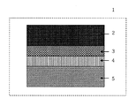
図1は、本発明の一実施形態に係る化学反応器1の構成図である。電極層3は、化学反応層2と固体電解質層4との間に、両者に接して構成される。固体電解質層4の電極層3に対する側の面には、酸化層5を有する。以下、被処理物質として、窒素酸化物とした場合について具体的に説明する。
実施例1
イオン伝導性を有する固体電解質層4として、酸化イットリウムで安定化したジルコニアを用い、その形状は、直径20mm、厚さ0.5mmの円板状とした。電極層3は、白金からなる電子伝導性物質と酸化イットリウムで安定化したジルコニアからなるイオン伝導性物質の混合比を体積比で40:60とした混合粉末に有機溶媒を加え、ペーストを作製し、固体電解質層4の片面に面積約1.8cm2となるようにスクリーン印刷した後、1200℃で熱処理することにより形成した。
【0031】
化学反応層2は、酸化ニッケルとニッケルからなる電子伝導性物質と酸化イットリウムで安定化したジルコニアからなるイオン伝導性物質の混合比を体積比で40:60とした混合粉末に有機溶媒を加えペーストを作製し、電極層3上に同一面積となるようにスクリーン印刷した後、1500℃で熱処理することにより形成した。
【0032】
酸化層5は、白金からなる電子伝導性物質と酸化イットリウムで安定化したジルコニアからなるイオン伝導性物質の混合比を体積比で60:40とした混合粉末に有機溶媒を加えペーストを作製し、化学反応層2と電極層3を形成した固体電解質層4の他方の面に面積約1.8cm2となるようにスクリーン印刷した後、1200℃で熱処理することにより形成し、化学反応器とした。
【0033】
このように形成した本発明に係る化学反応器による窒素酸化物の浄化方法の一例を、次に示す。被処理ガス中に化学反応器を配置し、電極層3と酸化層5に白金線をリード線として固定し、直流電源に接続、直流電圧を印加して電流を流した。窒素酸化物の分解、浄化特性の評価は、作動温度600℃から700℃の範囲で行った。
【0034】
被処理ガスとして、一酸化窒素1000ppm、酸素2%を含んだヘリウムバランスのモデル燃焼排ガスを流量50ml/minで流した。モデル燃焼排ガスが化学反応器を通過する前後における被処理ガス中の窒素酸化物濃度を化学発光式NOx計で、窒素及び酸素濃度をガスクロマトグラフィーで測定し、窒素酸化物の減少量から、窒素酸化物の浄化率を算出した。化学反応器を600℃に加熱した際、窒素酸化物浄化率50%を得るのに必要な電力は0.25Wであった。
【0035】
実施例2
電極層の電子伝導性物質とイオン伝導性物質の混合比を体積比で45.0:55.0とした以外は、実施例1と同様に化学反応器を作製した。この化学反応器の窒素酸化物の浄化特性を、実施例1と同様に評価した。その結果、窒素酸化物浄化率50%を得るのに必要な電力は0.21Wであった。
【0036】
実施例3
電極層の電子伝導性物質とイオン伝導性物質の混合比を体積比で31.5:68.5とした以外は、実施例1と同様に化学反応器を作製した。この化学反応器の窒素酸化物の浄化特性を、実施例1と同様に評価した。その結果、窒素酸化物浄化率50%を得るのに必要な電力は0.29Wであった。
【0037】
実施例4(参考実施例)
電極層の電子伝導性物質とイオン伝導性物質の混合比を体積比で67.5:32.5とした以外は、実施例1と同様に化学反応器を作製した。この化学反応器の窒素酸化物の浄化特性を、実施例1と同様に評価した。その結果、窒素酸化物浄化率50%を得るのに必要な電力は0.33Wであった。
【0038】
比較例1
電極層の電子伝導性物質とイオン伝導性物質の混合比を体積比で25.0:75.0とした以外は、実施例1と同様に化学反応器を作製した。この化学反応器の窒素酸化物の浄化特性を、実施例1と同様に評価した。その結果、窒素酸化物浄化率50%を得るのに必要な電力は0.45Wであった。
【0039】
比較例2
電極層の電子伝導性物質とイオン伝導性物質の混合比を体積比で80.0:20.0とした以外は、実施例1と同様に化学反応器を作製した。この化学反応器の窒素酸化物の浄化特性を、実施例1と同様に評価した。その結果、化学反応器の作動電力を0.8Wまで増大させても、窒素酸化物浄化率は35%以下にとどまった。
【0040】
【発明の効果】
以上詳述したように、本発明は、特定の電極層を有する化学反応器及び当該電極層を利用した化学反応システムに係るものであり、本発明によれば、以下のような格別の効果が奏される。
(1)少ない消費電力で高効率に被処理物質を処理できる化学反応器を提供することができる。
(2)電気化学セル方式の化学反応器において、元素をイオン化するための電子を供給する経路とイオン化した元素を触媒反応表面から取り除くための経路の構造を最適化することができる。
(3)電気化学セル方式の化学反応器において、その内部抵抗を十分に低下させることができる。
(4)高効率な窒素酸化物の分解が可能となり消費電力の低減化が可能となる。
(5)化学反応器の内部抵抗を低下させて窒素酸化物の浄化に必要な電力を顕著に低減させることができる。
(6)被処理物質の化学反応を妨害する酸素が過剰に存在する場合においても、高効率に被処理物質を処理できる化学反応器を提供することができる。
【図面の簡単な説明】
【図1】図1は、本発明の一実施形態に係る化学反応器の構成図である。
【符号の説明】
1 化学反応器
2 化学反応層
3 電極層
4 固体電解質層
5 酸化層[0001]
BACKGROUND OF THE INVENTION
The present invention relates to a chemical reactor having a specific electrode layer. More specifically, the present invention relates to an electrochemical cell type chemical reactor for performing a chemical reaction of a material to be treated. A chemical reactor that optimizes the structure of the supply path and the path for removing ionized elements from the catalytic reaction surface, for example, efficiently purifies nitrogen oxide from combustion exhaust gas containing oxygen with low power consumption It relates to the structure of a chemical reactor that makes it possible.
[0002]
[Prior art]
Currently, three-way catalysts are mainly used to purify nitrogen oxides generated from gasoline engines. However, in lean burn engines and diesel engines that can improve fuel efficiency, excessive oxygen is present in the combustion exhaust gas, so a drastic decrease in catalytic activity due to adsorption of oxygen on the surface of the three-way catalyst becomes a problem, and nitrogen oxidation I can't purify things.
[0003]
For this reason, as a method of removing oxygen from the catalyst surface, hydrocarbons are intermittently introduced and oxygen is released out of the system by reaction, but the problem of increased fuel consumption is unavoidable.
[0004]
On the other hand, by using a solid electrolyte membrane having oxygen ion conductivity and flowing current therethrough, oxygen in the exhaust gas is removed without being adsorbed on the catalyst surface. As a catalyst reactor, a system that removes surface oxygen and simultaneously decomposes nitrogen oxides into oxygen and nitrogen by applying a voltage to a solid electrolyte sandwiched between electrodes (electrochemical cell method) ) Has been proposed.
[0005]
Here, prior documents are presented as follows: Electrochemical Soc. , 122, 869, (1975) show that when a platinum electrode is formed on both sides of zirconia stabilized with scandium oxide and a voltage is applied, nitrogen oxide is decomposed into nitrogen and oxygen. . (2) J. Org. Chem. Soc. Faraday Trans. 91, 1995, (1995), palladium electrodes are formed on both sides of zirconia stabilized with yttrium oxide, and a voltage is applied to oxidize nitrogen in a mixed gas of nitrogen oxide, hydrocarbon, and oxygen. Has been shown to decompose into nitrogen and oxygen.
[0006]
However, in the conventional method as described above, when excess oxygen is present in the combustion exhaust gas, the coexisting oxygen is preferentially ionized and flows in the solid electrolyte in the electrode portion, so that nitrogen oxides are reduced. In order to decompose, it is necessary to pass a large amount of current. For this reason, application of a high voltage is required, and power consumption increases, which has been a major obstacle to practical use.
[0007]
[Problems to be solved by the invention]
The present invention has been made to solve the above-mentioned problems, and the present inventors have provided, in a chemical reactor, an electrode layer made of a mixture of an ion conductor and an electron conductor at a lower part of a portion that performs a chemical reaction. Install and mix ion conductor and electron conductor so that the process of efficiently supplying the electrons to the oxygen that occupies the active site of the chemical reaction in the chemical reaction layer and moving and removing the ionized oxygen can be performed. It has been found that by optimizing the ratio, the material to be treated can be treated with low power consumption and high efficiency, and the intended purpose can be achieved.
[0008]
That is, the present invention drastically solves the above-mentioned problems of the prior art, and 1) optimizes the structure of a path for supplying electrons to ionize oxygen and a path for removing ionized oxygen from the catalytic reaction surface. 2) A new chemistry that makes it possible to reduce the power required for decomposing nitrogen oxides in an electrochemical cell system and to purify nitrogen oxides with low power consumption and high efficiency. The object is to provide a reactor.
[0009]
[Means for Solving the Problems]
The present invention for solving the above-described problems comprises the following technical means.
(1) In a chemical reactor for performing a chemical reaction of a substance to be treated,
(A) a chemical reaction layer that promotes a chemical reaction of the substance to be treated;
(B) an electrode layer adjacent to the chemical reaction layer;
(C) a solid electrolyte layer that moves and removes ionized oxygen from the electrode layer by the action of an electric field, and (d) an oxide layer that releases electrons from the oxygen ions and returns them to the oxygen to be discharged out of the system. structure, has a,
The electrode layer includes an electron conductive phase that conducts electrons to ionize elements contained in the material to be treated in the chemical reaction layer, and an ion conductive phase that conducts elements ionized by the chemical reaction. it, and chemical reactors, characterized in, that the volume ratio of the ion-conducting phase is 50% to 70% in the mixing ratio of the electron-conducting phase and the ion-conducting phase.
(2) The chemical reactor according to (1), wherein the electrode layer is made of an oxide, a metal, or a mixture of both.
(3) The chemical reactor according to (1), wherein particles of the ion conductive material and the electron conductive material constituting the ion conductive phase and the electron conductive phase are uniformly dispersed.
(4) The substance to be treated is nitrogen oxide, the nitrogen oxide is reduced in the chemical reaction layer to generate oxygen ions, and the oxygen ions are conducted in the ion conduction phase in the electrode layer ( The chemical reactor according to 1).
[0010]
DETAILED DESCRIPTION OF THE INVENTION
Next, the present invention will be described in more detail.
As a preferred embodiment of the present invention, the present invention is applied to, for example, a nitrogen oxide light removal system. Hereinafter, the present invention will be described focusing on the configuration of this system, but the present invention is not limited to this.
A chemical reactor for performing a chemical reaction of a material to be treated according to the present invention includes a chemical reaction layer for advancing the chemical reaction of the material to be treated, an electrode layer for removing oxygen in the chemical reaction layer, and ionized oxygen A solid electrolyte layer that moves and removes from the electrode layer by the action of an electric field, and an oxide layer that releases electrons from oxygen ions, returns them to oxygen, and discharges them out of the system. In this case, all or part of the solid electrolyte layer and the oxide layer can be omitted by integrating or partially adding the function of the electrode layer and the function thereof.
[0011]
The chemical reaction layer that performs the chemical reaction of the target substance preferably includes a reduction phase that supplies electrons to the elements contained in the target substance to generate ions, and an ion conduction phase that conducts ions from the reduction phase. It has. Preferably, when oxygen is contained in the substance to be treated, or when oxygen is generated before or after the reaction, it is contained in the substance to be treated in the route until the substance to be treated reaches the chemical reaction layer. It is desirable to have an optional catalyst that has an oxygen reducing action to remove some or all of the oxygen. More preferably, it is desirable to cover a part or all of the chemical reaction layer.
[0012]
Preferably, the substance to be treated is nitrogen oxides in the combustion exhaust gas. The nitrogen oxides are reduced in the reduction phase to generate oxygen ions, and the oxygen ions are conducted in the ion conduction phase. However, the substance to be treated in the present invention is not limited to nitrogen oxides, and appropriate substances to be treated are targeted. With the chemical reactor of the present invention, for example, carbon monoxide can be reduced to produce carbon monoxide, a mixed gas of hydrogen and carbon monoxide can be produced from methane, or hydrogen can be produced from water. can do. Therefore, the said chemical reactor can be arbitrarily comprised according to those to-be-processed substances.
[0013]
The structure and form of the chemical reactor is preferably, for example, tubular, flat plate, honeycomb, etc. In particular, one or more through-holes having a pair of openings such as tubular or honeycomb are used. It is preferable that a plurality of the chemical reaction portions are located in each through hole. It is also preferable from the viewpoint of improving the reaction efficiency to have a structure of a microstructure such as a composite powder having a chemical reactor configuration. However, it is not limited to these.
[0014]
In the present invention, the reducing phase constituting the chemical reaction layer is preferably porous, for example, and selectively adsorbs a substance to be reacted. In the reduction phase, it is preferable that the reduction phase is made of a conductive substance in order to supply electrons to the elements contained in the material to be treated to generate ions and transmit the generated ions to the ion conduction phase. Further, in order to promote the transfer of electrons and ions, it may be composed of a mixed conductive material having both electron conductivity and ion conductivity characteristics, or may be composed of a mixture of an electron conductive material and an ion conductive material. More preferred. The reduced phase may have a structure in which at least two phases of these substances are laminated. However, they are not limited.
[0015]
The conductive substance and ionic conductive substance used as the reducing phase are not particularly limited. As the conductive substance, a noble metal such as platinum or palladium, or a metal oxide such as nickel oxide, cobalt oxide, copper oxide, lanthanum manganite, lanthanum cobaltite, or lanthanum chromite is used. Alkaline earth-containing oxides or theolite that selectively adsorb the substance to be treated are also used as the reducing phase. It is also preferable to use at least one kind of the substance as a mixture with at least one kind of ion conductive substance. As the ion conductive substance, zirconia stabilized with yttria or scandium oxide, ceria stabilized with gadolinium oxide or samarium oxide, lanthanum gallate and the like are used.
[0016]
It is also preferable that the reducing phase has a structure in which at least two phases of the above substances are laminated. More preferably, the reduction phase has a structure in which a conductive material phase made of a noble metal such as platinum and a mixture phase of nickel oxide and a mixed phase of zirconia stabilized with yttria or scandium oxide are laminated. In the present invention, the ion conductive phase constituting the chemical reaction layer is made of a solid electrolyte having ion conductivity. Preferably, the ion conductive phase is made of a solid electrolyte having oxygen ion conductivity. Examples of the solid electrolyte having oxygen ion conductivity include, but are not particularly limited to, zirconia stabilized with yttria or scandium oxide, ceria stabilized with gadolinium oxide or samarium oxide, and lanthanum gallate. Preferably, zirconia stabilized with yttria or scandium oxide having high conductivity and strength and excellent long-term stability is used.
[0017]
Next, in the present invention, examples of the electron conductive material used for the electrode layer include metals such as gold, silver, platinum, palladium, nickel, cobalt oxide, nickel oxide, copper oxide, lanthanum chromite, lanthanum manganite, Examples thereof include metal oxides such as lanthanum cobaltite. As the ion conductive substance, an oxygen ion conductive substance is preferably used. As the oxygen ion conductive substance, zirconia stabilized with yttrium oxide or scandium oxide, ceria stabilized with gadolinium oxide or samarium oxide, lanthanum gallate, or the like is used.
[0018]
The electrode layer needs to function to supply current necessary for ionization of oxygen to the upper chemical reaction layer and to release ionized oxygen to the outside of the system through the solid electrolyte layer adjacent to the lower portion or directly. The electronic conduction phase constituting this is because, for example, the thermal stability at the time of chemical reactor production and operation, the absence of a chemical reaction with the ion conductive material, and the high electron conductivity. It is preferable to use platinum. As the ion conductive material, it is preferable to use yttrium oxide or zirconia stabilized with scandium oxide having excellent electrical and chemical long-term stability, or cerium oxide added with samarium or gadolinium having low resistance characteristics.
[0019]
As shown in the examples described later, the ratio of the electron conductive material and the ion conductive material used as the electrode layer is 30% or more and 70% or less as the volume ratio of the electron conductive material. A chemical reactor is preferable because nitrogen oxides can be purified with high efficiency and power consumption can be reduced. Further, it is preferable that the particles of the electron conductive substance and the ion conductive substance are uniformly dispersed. When the proportion of the electron conductive material is less than 30%, the particles made of the electron conductive material cannot be contacted with each other and are isolated, and the electron conductivity is lowered.
[0020]
When the proportion of the electron conductive material exceeds 70%, sufficient electron conductivity can be ensured. However, since the particles made of the ion conductive material cannot contact each other and are isolated, the ion conductivity Will fall. When the ratio of the electron conductive material is 30% or more and 70% or less and the particles are uniformly dispersed in the lower cathode, the particles made of the electron conductive material can come into contact with each other at the same time. Since particles made of a conductive substance can be in contact with each other, both electron conductivity and ion conductivity are not lowered, and it is possible to decompose nitrogen oxide with high efficiency, thereby reducing power consumption, which is preferable.
[0021]
The ratio between the electron conductive material and the ion conductive material is more preferably in the above-mentioned range of 30-70% depending on the electric conductivity in the operating conditions of the chemical reactor. In many cases, when the volume ratio of the ion conductive material is 50% or more, the resistance of the chemical reactor is particularly lowered, and the electric power necessary for the purification of nitrogen oxides can be reduced. For this reason, the volume ratio of the ion conductive material is more preferably 50% or more and 70% or less.
[0022]
The thickness of the electrode layer is desirably thin enough to have a smooth conduction path in order to supply electrons to the chemical reaction layer and conduct ions. As a result, the volume ratio of the above-mentioned electron conductor and ion conductor is 30 to 70%, which is a ratio suitable for forming a three-dimensional network, and a ratio suitable for forming a two-dimensional network. The vicinity of 50% -50% is more preferable.
[0023]
Next, the solid electrolyte layer can be made of the same material as the ion conductive material used in the reduction phase. As the solid electrolyte, any substance having ion conductivity can be used. Examples of the solid electrolyte having oxygen ion conductivity include zirconia stabilized with yttrium oxide or scandium oxide, ceria stabilized with gadolinium oxide or samarium oxide, lanthanum gallate, and the like. However, it is not limited to these, and an appropriate material can be used. It is more preferable that the film quality is dense and the film thickness is as thin as possible because it is necessary to reduce the electric power required for the operation of the chemical reactor.
[0024]
Next, the oxide layer contains a conductive substance in order to emit electrons from ions from the ion conductive phase. In order to promote the transmission of electrons and ions, it is preferable that the material is composed of a mixed conductive material having both electron conductivity and ion conductivity properties, or a mixture of an electron conductive material and an ion conductive material. The conductive substance and ion conductive substance used as the oxide layer are not particularly limited. As the conductive substance, a noble metal such as platinum or palladium, or a metal oxide such as nickel oxide, cobalt oxide, copper oxide, lanthanum manganite, lanthanum cobaltite, or lanthanum chromite is used. As the ion conductive substance, zirconia stabilized with yttria or scandium oxide, ceria stabilized with gadolinium oxide or samarium oxide, and lanthanum gallate are used.
[0025]
In the present invention, as described above, an oxygen reduction catalyst can be formed as necessary. The form of the oxygen reducing catalyst may be powder, film, or the like. The catalyst reaction layer can be formed by filling a container having a gas inlet / outlet with powder. In addition, a catalyst reaction layer may be used in which a powder of an oxidation catalyst is supported on a tubular or honeycomb-shaped carrier surface or an oxygen-reducing catalyst is formed as a porous film on the carrier surface. More preferably, the catalyst reaction part is a porous membrane made of an oxygen reducing catalyst so as to cover the reduction phase constituting the chemical reaction layer. Since the catalytic reaction active point increases as the contact area with the substance to be treated increases, the specific surface area of the oxidation catalyst phase is preferably as large as possible, and the particles forming the oxidation catalyst powder and the oxidation catalyst film are as fine as possible.
[0026]
The chemical reactor of the present invention is characterized by having the chemical reaction layer and an electrode layer adjacent to the chemical reaction layer. As described above, these include a solid electrolyte layer, an oxidation layer, and an oxygen reduction catalyst. For example, a lead wire can be fixed to the electrode layer and the oxide layer, a DC power supply can be applied, and a DC voltage can be applied to flow current. These specific configurations and their materials may be appropriately selected and designed according to the purpose of use, and are not particularly limited.
Further, as described above, each of the solid electrolyte layer and the oxide layer can be integrated with the electrode layer and the configuration and function thereof, whereby the formation thereof can be arbitrarily omitted. Since chemical reactors are required to reduce the power required to operate the chemical reactors as much as possible, it is important to make the film thickness as thin as possible. Can do.
[0027]
[Action]
The present invention relates to a chemical reactor for carrying out a chemical reaction of a substance to be treated, comprising an electrode layer adjacent to the chemical reaction layer for advancing the chemical reaction of the substance to be treated. Is. In the present invention, in the chemical reaction layer, the electrode layer includes an electron conduction phase having a function of conducting electrons given to the chemical reaction layer in order to ionize an element contained in the substance to be treated; And an ion conducting phase having a function of conducting elements ionized by the reaction. Thereby, the electrode layer supplies electrons to the element contained in the material to be processed through the electron conduction phase, ionizes the element in the chemical reaction layer to generate ions, and converts the ions to the ions. It is possible to perform the discharge out of the system through the conductive phase with high efficiency.
[0028]
That is, the electrode layer has a function of realizing efficient supply of electrons to the element occupying the active point of the chemical reaction and efficient removal and movement of the ionized element in the chemical reaction layer. As a result, the internal resistance in the chemical reactor can be reduced, and the material to be treated can be processed with high efficiency and low power consumption. Thus, the present invention optimizes the structure of the path for supplying electrons for ionizing elements in the chemical reaction layer and the path for removing the ionized elements from the catalytic reaction surface. To provide a chemical reactor that can reduce the power consumption required when decomposing nitrogen oxides, for example, and can purify nitrogen oxides with low power consumption and high efficiency. Is made possible.
[0029]
In the present invention, the volume ratio of the ion conductive substance and the electron conductive substance, which are components constituting the ion conductive phase and the electron conductive phase constituting the electrode layer, is 30-70% as shown in the examples described later. The specific resistance of the chemical reactor is reduced specifically by setting the specific range of the particles and dispersing the particles uniformly, for example, the power required for the purification of nitrogen oxides is reduced. It can be significantly reduced. In the electrode layer of the chemical reactor, the present invention significantly reduces the internal resistance of the chemical reactor by optimizing the configuration of the ionic conductor and the electron conductor, thereby achieving high efficiency with low power consumption. In particular, it is proved that nitrogen oxides can be purified, and is useful for enabling practical use of an electrochemical cell type chemical reactor.
[0030]
【Example】
EXAMPLES Next, although this invention is demonstrated concretely based on an Example, this invention is not limited at all by the following Examples.
FIG. 1 is a configuration diagram of a
Example 1
As the solid electrolyte layer 4 having ion conductivity, zirconia stabilized with yttrium oxide was used, and the shape thereof was a disk shape having a diameter of 20 mm and a thickness of 0.5 mm. The electrode layer 3 is prepared by adding an organic solvent to a mixed powder in which the volume ratio of the electron conductive material made of platinum and the ion conductive material made of zirconia stabilized with yttrium oxide is 40:60. The solid electrolyte layer 4 was formed by subjecting one surface of the solid electrolyte layer 4 to screen printing so as to have an area of about 1.8 cm 2 , followed by heat treatment at 1200 ° C.
[0031]
The chemical reaction layer 2 is a paste in which an organic solvent is added to a mixed powder in which the mixing ratio of an electron conductive material composed of nickel oxide and nickel and an ion conductive material composed of zirconia stabilized with yttrium oxide is 40:60 by volume. Was formed and screen-printed on the electrode layer 3 so as to have the same area, followed by heat treatment at 1500 ° C.
[0032]
The oxide layer 5 is prepared by adding an organic solvent to a mixed powder in which the volume ratio of the electron conductive material made of platinum and the ion conductive material made of zirconia stabilized with yttrium oxide is 60:40 by volume, The chemical reaction layer 2 and the electrode layer 3 were formed on the other surface of the solid electrolyte layer 4 by screen printing so that the area was about 1.8 cm 2 and then heat treated at 1200 ° C. to form a chemical reactor. .
[0033]
An example of a method for purifying nitrogen oxides by the chemical reactor according to the present invention formed as described above will be described below. A chemical reactor was placed in the gas to be treated, a platinum wire was fixed as a lead wire to the electrode layer 3 and the oxide layer 5, connected to a DC power source, and a DC voltage was applied to pass a current. The decomposition and purification characteristics of nitrogen oxides were evaluated in the operating temperature range of 600 ° C to 700 ° C.
[0034]
As a gas to be treated, a model combustion exhaust gas of helium balance containing 1000 ppm of nitric oxide and 2% of oxygen was flowed at a flow rate of 50 ml / min. The nitrogen oxide concentration in the gas to be treated before and after the model combustion exhaust gas passes through the chemical reactor is measured with a chemiluminescent NOx meter, and the nitrogen and oxygen concentrations are measured with gas chromatography. The purification rate of oxide was calculated. When the chemical reactor was heated to 600 ° C., the electric power required to obtain a nitrogen oxide purification rate of 50% was 0.25 W.
[0035]
Example 2
A chemical reactor was prepared in the same manner as in Example 1 except that the mixing ratio of the electron conductive material and the ion conductive material in the electrode layer was set to 45.0: 55.0 by volume. The nitrogen oxide purification characteristics of this chemical reactor were evaluated in the same manner as in Example 1. As a result, the electric power necessary to obtain a nitrogen oxide purification rate of 50% was 0.21 W.
[0036]
Example 3
A chemical reactor was prepared in the same manner as in Example 1 except that the mixing ratio of the electron conductive material and the ion conductive material in the electrode layer was 31.5: 68.5 in volume ratio. The nitrogen oxide purification characteristics of this chemical reactor were evaluated in the same manner as in Example 1. As a result, the electric power necessary to obtain a nitrogen oxide purification rate of 50% was 0.29 W.
[0037]
Example 4 (Reference Example)
A chemical reactor was prepared in the same manner as in Example 1 except that the mixing ratio of the electron conductive material and the ion conductive material in the electrode layer was set to 67.5: 32.5 by volume. The nitrogen oxide purification characteristics of this chemical reactor were evaluated in the same manner as in Example 1. As a result, the electric power necessary to obtain a nitrogen oxide purification rate of 50% was 0.33 W.
[0038]
Comparative Example 1
A chemical reactor was prepared in the same manner as in Example 1 except that the mixing ratio of the electron conductive material and the ion conductive material in the electrode layer was 25.0: 75.0 in terms of volume ratio. The nitrogen oxide purification characteristics of this chemical reactor were evaluated in the same manner as in Example 1. As a result, the electric power necessary to obtain a nitrogen oxide purification rate of 50% was 0.45 W.
[0039]
Comparative Example 2
A chemical reactor was prepared in the same manner as in Example 1 except that the mixing ratio of the electron conductive material and the ion conductive material in the electrode layer was set to 80.0: 20.0 by volume. The nitrogen oxide purification characteristics of this chemical reactor were evaluated in the same manner as in Example 1. As a result, even if the operating power of the chemical reactor was increased to 0.8 W, the nitrogen oxide purification rate remained at 35% or less.
[0040]
【The invention's effect】
As described above in detail, the present invention relates to a chemical reactor having a specific electrode layer and a chemical reaction system using the electrode layer. According to the present invention, the following special effects are obtained. Played.
(1) It is possible to provide a chemical reactor capable of processing a material to be processed with low power consumption and high efficiency.
(2) In an electrochemical cell type chemical reactor, the structure of the path for supplying electrons for ionizing the element and the path for removing the ionized element from the catalytic reaction surface can be optimized.
(3) In an electrochemical cell type chemical reactor, the internal resistance can be sufficiently reduced.
(4) Nitrogen oxide can be decomposed with high efficiency and power consumption can be reduced.
(5) The internal resistance of the chemical reactor can be reduced to significantly reduce the power required for purifying nitrogen oxides.
(6) It is possible to provide a chemical reactor capable of treating a material to be treated with high efficiency even when oxygen that interferes with the chemical reaction of the material to be treated is excessively present.
[Brief description of the drawings]
FIG. 1 is a configuration diagram of a chemical reactor according to an embodiment of the present invention.
[Explanation of symbols]
DESCRIPTION OF
Claims (4)
(1)前記被処理物質の化学反応を進行させる化学反応層、
(2)前記化学反応層に隣接した電極層、
(3)イオン化した酸素を電界の作用により電極層から移動除去させる固体電解質層、及び
(4)酸素イオンから電子を放出させて酸素に戻して系外に放出させるための酸化層、とからなる構造、を有し、
前記電極層が、前記化学反応層において前記被処理物質中に含まれる元素をイオン化するために与える電子を伝導する電子伝導相と、前記化学反応によりイオン化した元素を伝導するイオン伝導相とからなること、及び前記イオン伝導相と前記電子伝導相の混合比率におけるイオン伝導相の体積割合が50〜70%であること、を特徴とする化学反応器。In chemical reactors for conducting chemical reactions of substances to be treated,
(1) a chemical reaction layer that promotes a chemical reaction of the substance to be treated;
(2) an electrode layer adjacent to the chemical reaction layer;
(3) a solid electrolyte layer that moves and removes ionized oxygen from the electrode layer by the action of an electric field; and (4) an oxide layer that releases electrons from oxygen ions to return them to oxygen and release them outside the system. structure, have,
The electrode layer includes an electron conductive phase that conducts electrons to ionize elements contained in the material to be treated in the chemical reaction layer, and an ion conductive phase that conducts elements ionized by the chemical reaction. it, and chemical reactors, characterized in, that the volume ratio of the ion-conducting phase is 50% to 70% in the mixing ratio of the electron-conducting phase and the ion-conducting phase.
Priority Applications (4)
| Application Number | Priority Date | Filing Date | Title |
|---|---|---|---|
| JP2002073437A JP4132893B2 (en) | 2002-03-18 | 2002-03-18 | Electrode material for chemical reactor |
| AU2003227181A AU2003227181A1 (en) | 2002-03-15 | 2003-03-17 | Chemical reactor for nitrogen oxide removal and method of removing nitrogen oxide |
| PCT/JP2003/003178 WO2003078031A1 (en) | 2002-03-15 | 2003-03-17 | Chemical reactor for nitrogen oxide removal and method of removing nitrogen oxide |
| US10/506,620 US20050167286A1 (en) | 2002-03-15 | 2003-03-17 | Chemical reactor for nitrogen oxide removal and method of removing nitrogen oxide |
Applications Claiming Priority (1)
| Application Number | Priority Date | Filing Date | Title |
|---|---|---|---|
| JP2002073437A JP4132893B2 (en) | 2002-03-18 | 2002-03-18 | Electrode material for chemical reactor |
Publications (2)
| Publication Number | Publication Date |
|---|---|
| JP2003265950A JP2003265950A (en) | 2003-09-24 |
| JP4132893B2 true JP4132893B2 (en) | 2008-08-13 |
Family
ID=29203101
Family Applications (1)
| Application Number | Title | Priority Date | Filing Date |
|---|---|---|---|
| JP2002073437A Expired - Lifetime JP4132893B2 (en) | 2002-03-15 | 2002-03-18 | Electrode material for chemical reactor |
Country Status (1)
| Country | Link |
|---|---|
| JP (1) | JP4132893B2 (en) |
Families Citing this family (2)
| Publication number | Priority date | Publication date | Assignee | Title |
|---|---|---|---|---|
| JP4822494B2 (en) * | 2004-10-29 | 2011-11-24 | 独立行政法人産業技術総合研究所 | Electrochemical cell type chemical reactor |
| JP5057018B2 (en) | 2006-06-30 | 2012-10-24 | 独立行政法人産業技術総合研究所 | Electrochemical cell type gas sensor |
-
2002
- 2002-03-18 JP JP2002073437A patent/JP4132893B2/en not_active Expired - Lifetime
Also Published As
| Publication number | Publication date |
|---|---|
| JP2003265950A (en) | 2003-09-24 |
Similar Documents
| Publication | Publication Date | Title |
|---|---|---|
| JP5614521B2 (en) | Solid carbon decomposition type ceramic chemical reactor | |
| JP3626971B2 (en) | Chemical reactor | |
| JP3657542B2 (en) | Chemical reactor | |
| JP4057823B2 (en) | Nitrogen oxide purification chemical reactor and nitrogen oxide purification method | |
| JP4395567B2 (en) | Electrochemical element and exhaust gas purification method | |
| JP5252362B2 (en) | Ceramic electrode | |
| JP4201319B2 (en) | Electrochemical cell type chemical reaction system | |
| JP4132893B2 (en) | Electrode material for chemical reactor | |
| JP2008307493A (en) | Self-organizing porous thin film type electrochemical reactor | |
| JP4193929B2 (en) | Energy saving electrochemical reaction system and activation method thereof | |
| CN100337739C (en) | Chemical reaction system of electrochemical cell type, method for activation thereof and method for reaction | |
| US20050167286A1 (en) | Chemical reactor for nitrogen oxide removal and method of removing nitrogen oxide | |
| JP6575924B2 (en) | NOx purification device and NOx purification method using the same | |
| JP4521515B2 (en) | Catalytic electrochemical reactor | |
| JP4822494B2 (en) | Electrochemical cell type chemical reactor | |
| JP4318281B2 (en) | Nitrogen oxide removal system | |
| JP4317683B2 (en) | Nitrogen oxide purification chemical reactor | |
| JP2008307492A (en) | Electrochemical reactor having electrode for stable and high efficient operation | |
| JP2009233618A (en) | Oxidation apparatus | |
| JP2008110277A (en) | Low-temperature operation type electrochemical reactor | |
| JP2004154657A (en) | Reaction method using oxidation-reduction reactor | |
| JP2006122847A (en) | Operation method of chemical reactor for performing catalyst action and electrochemical action | |
| JP2022189523A (en) | NOx PURIFICATION DEVICE AND NOx PURIFICATION METHOD WITH USE THEREOF | |
| JP2004223401A (en) | Element for purification of exhaust gas | |
| JPH04190830A (en) | Removal of nitrogen oxide |
Legal Events
| Date | Code | Title | Description |
|---|---|---|---|
| A711 | Notification of change in applicant |
Free format text: JAPANESE INTERMEDIATE CODE: A711 Effective date: 20041013 |
|
| RD02 | Notification of acceptance of power of attorney |
Free format text: JAPANESE INTERMEDIATE CODE: A7422 Effective date: 20041013 |
|
| A521 | Request for written amendment filed |
Free format text: JAPANESE INTERMEDIATE CODE: A821 Effective date: 20041014 |
|
| A131 | Notification of reasons for refusal |
Free format text: JAPANESE INTERMEDIATE CODE: A131 Effective date: 20070831 |
|
| A521 | Request for written amendment filed |
Free format text: JAPANESE INTERMEDIATE CODE: A523 Effective date: 20071030 |
|
| A131 | Notification of reasons for refusal |
Free format text: JAPANESE INTERMEDIATE CODE: A131 Effective date: 20071203 |
|
| A521 | Request for written amendment filed |
Free format text: JAPANESE INTERMEDIATE CODE: A523 Effective date: 20080131 |
|
| TRDD | Decision of grant or rejection written | ||
| A01 | Written decision to grant a patent or to grant a registration (utility model) |
Free format text: JAPANESE INTERMEDIATE CODE: A01 Effective date: 20080507 |
|
| A01 | Written decision to grant a patent or to grant a registration (utility model) |
Free format text: JAPANESE INTERMEDIATE CODE: A01 |
|
| A61 | First payment of annual fees (during grant procedure) |
Free format text: JAPANESE INTERMEDIATE CODE: A61 Effective date: 20080602 |
|
| FPAY | Renewal fee payment (event date is renewal date of database) |
Free format text: PAYMENT UNTIL: 20110606 Year of fee payment: 3 |
|
| R150 | Certificate of patent or registration of utility model |
Ref document number: 4132893 Country of ref document: JP Free format text: JAPANESE INTERMEDIATE CODE: R150 Free format text: JAPANESE INTERMEDIATE CODE: R150 |
|
| R250 | Receipt of annual fees |
Free format text: JAPANESE INTERMEDIATE CODE: R250 |
|
| FPAY | Renewal fee payment (event date is renewal date of database) |
Free format text: PAYMENT UNTIL: 20130606 Year of fee payment: 5 |
|
| R250 | Receipt of annual fees |
Free format text: JAPANESE INTERMEDIATE CODE: R250 |
|
| R250 | Receipt of annual fees |
Free format text: JAPANESE INTERMEDIATE CODE: R250 |
|
| R250 | Receipt of annual fees |
Free format text: JAPANESE INTERMEDIATE CODE: R250 |
|
| R250 | Receipt of annual fees |
Free format text: JAPANESE INTERMEDIATE CODE: R250 |
|
| S533 | Written request for registration of change of name |
Free format text: JAPANESE INTERMEDIATE CODE: R313533 |
|
| R350 | Written notification of registration of transfer |
Free format text: JAPANESE INTERMEDIATE CODE: R350 |
|
| R250 | Receipt of annual fees |
Free format text: JAPANESE INTERMEDIATE CODE: R250 |
|
| R250 | Receipt of annual fees |
Free format text: JAPANESE INTERMEDIATE CODE: R250 |
|
| R250 | Receipt of annual fees |
Free format text: JAPANESE INTERMEDIATE CODE: R250 |
|
| R250 | Receipt of annual fees |
Free format text: JAPANESE INTERMEDIATE CODE: R250 |
|
| R250 | Receipt of annual fees |
Free format text: JAPANESE INTERMEDIATE CODE: R250 |
|
| R250 | Receipt of annual fees |
Free format text: JAPANESE INTERMEDIATE CODE: R250 |
|
| EXPY | Cancellation because of completion of term |