JP4131045B2 - Moving body position detection device and industrial vehicle - Google Patents
Moving body position detection device and industrial vehicle Download PDFInfo
- Publication number
- JP4131045B2 JP4131045B2 JP22494698A JP22494698A JP4131045B2 JP 4131045 B2 JP4131045 B2 JP 4131045B2 JP 22494698 A JP22494698 A JP 22494698A JP 22494698 A JP22494698 A JP 22494698A JP 4131045 B2 JP4131045 B2 JP 4131045B2
- Authority
- JP
- Japan
- Prior art keywords
- piston
- reference position
- lift
- detected
- ultrasonic
- Prior art date
- Legal status (The legal status is an assumption and is not a legal conclusion. Google has not performed a legal analysis and makes no representation as to the accuracy of the status listed.)
- Expired - Fee Related
Links
Images


Landscapes
- Length Measuring Devices Characterised By Use Of Acoustic Means (AREA)
- Forklifts And Lifting Vehicles (AREA)
Abstract
Description
【0001】
【発明の属する技術分野】
本発明は、移動体の位置検出装置、及び産業車両に関するものである。
【0002】
【従来の技術】
フォークリフトとして、フォークを予め設定した揚高位置まで自動的に昇降動作させる自動制御装置を備えたものが提案されている。この種の自動制御装置では、フォークの揚高位置を連続的に検出する揚高検出センサが必要である。
【0003】
従来、揚高を連続的に検出可能な揚高検出センサとしては、ワイヤ巻き取り方式のリール式センサが知られている。リール式センサは、先端がインナマストに接続されたワイヤを巻き取る回転方向に付勢されたリールの回転変位量を、ポテンショメータ等の回転変位センサにて検出するものである。
【0004】
【発明が解決しようとする課題】
しかしながら、リール式センサは、構造上ワイヤ等の機能部分が外部に露出する。従って、荷役作業においてワイヤに障害物が当たったりし易く、ポテンショメータが損傷したり、ワイヤが切断されるといった可能性があり、信頼性が十分でない。
【0005】
そこで、このような問題を解消するため、本出願人は、リフトシリンダに内蔵した超音波センサを用いてリフトシリンダのピストン位置を検出し、検出したピストン位置から揚高位置を求める揚高検出装置を提案している。つまり、リフトシリンダのシリンダボディの下端内部に設けた超音波素子から超音波をピストンの端面に向かって送信し、ピストンの端面で反射した超音波を再び超音波素子で受信する。そして、超音波素子から超音波を送信した時点から反射波が受信された時点までの経過時間から、ピストンまでの距離、すなわち、ピストン位置を求める。さらに、求めたピストン位置からフォークの揚高位置を求める。このような揚高検出装置によれば、リール式センサと違って機能部分が損傷し難くなり、信頼性が向上する。
【0006】
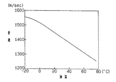
ところで、このようにシリンダボディの下端内部に設けた超音波センサからピストンまで超音波を送信する場合、超音波センサから送信された超音波は、油室内の作動油中を伝播することになる。ところが、超音波の伝播速度(音速)は、図6に示すように、媒体である作動油の温度によって変化する。その結果、超音波センサに検出されるピストン位置は、図7に示すように、作動油の温度に応じて変動する。一方、リフトシリンダの作動油の温度は、周囲の温度や、フォークリフトの使用開始からの荷役作業時間等によって大きく変化する。
【0007】
従って、リフトシリンダのピストン位置を、作動油の温度に基づく検出誤差を殆ど含まずに検出することができないため、正しい揚高位置を検出することができなかった。また、正しい揚高位置を検出できないため、検出した揚高位置に基づいて行う制御の精度を向上させることができなかった。
【0008】
本発明は、上記問題点を解決するためになされたものであって、その第1の目的は、流体圧シリンダ内の作動流体の温度に基づく検出誤差をできるだけ含まずに、移動体の位置を連続的に検出することができる移動体の位置検出装置を提供することにある。
【0010】
又、第2の目的は、搭載する流体圧シリンダにて連続的に移動される移動体の位置に基づいて行う制御の精度を向上することができる産業車両を提供することにある。
【0011】
【課題を解決するための手段】
上記第1の目的を達成するため、請求項1に記載の発明は、移動体を移動させる流体圧シリンダのピストンに向かって作動流体を媒介して超音波を送信するとともに前記ピストンからの反射波を受信し、前記超音波を送信した時点から前記反射波が受信された時点までの経過時間に比例する距離検出信号を生成する距離検出手段と、前記ピストンが予め設定された基準位置にあることを検出する基準位置検出手段と、前記基準位置検出手段にて前記ピストンが前記基準位置にあることが検出されたとき前記距離検出手段が生成する前記距離検出信号と、該基準位置に対応する基準量とを用いて、前記ピストンの各位置に対して前記距離検出手段が生成する前記距離検出信号から前記ピストンの位置に対応する位置検出信号を生成する位置信号生成手段とを備え、前記ピストンに向かって超音波を送信する超音波送信部と前記ピストンからの反射波を受信する超音波受信部は、前記流体圧シリンダのシリンダボディの長さ方向の一端の内部に設けられ、前記基準位置は、前記流体圧シリンダの長さ方向に移動する前記ピストンの移動範囲内に複数設定され、前記基準位置検出手段は、各基準位置をそれぞれ区別して検出し、前記位置信号生成手段は、前記基準位置検出手段にて各基準位置のうちの1つが検出されたとき前記距離検出手段が検出した前記距離検出信号と、検出された該基準位置との対応関係を用いて、前記距離検出信号から前記ピストンの位置に対応する前記位置検出信号を生成する。
【0012】
請求項2に記載の発明は、請求項1に記載の発明において、前記超音波送信部と超音波受信部は、前記流体圧シリンダのシリンダボディのボトムブロックに固定されており、該ボトムブロックには、前記作動流体を給排するためのポートが設けられている。
【0013】
請求項3に記載の発明は、請求項1又は請求項2に記載の発明において、前記流体圧シリンダは、荷役用アタッチメントを前記移動体として備えたフォークリフトのリフトシリンダであって、前記基準位置は、前記荷役用アタッチメントの全揚高範囲に対応する前記リフトシリンダのピストンの移動範囲内に設定されている。
【0015】
第2の目的を達成するため、請求項4に記載の発明は、産業車両は、請求項1〜請求項3のいずれか一項に記載の移動体の位置検出装置を備えている。
(作用)
請求項1に記載の発明によれば、ピストンに向かって送信された超音波は、ある温度の作動流体中を伝播してピストンで反射され、再び受信される。このとき、超音波の送信時点から受信時点までの経過時間に比例する距離検出値が距離検出手段によって検出されるが、この距離検出値には作動流体の温度に応じた検出誤差が含まれる。一方、基準位置検出手段によって流体圧シリンダが予め設定された基準位置となったことが検出されたとき、同基準位置に対して検出される距離検出値と、この基準位置との対応関係は、そのときの作動流体の温度が考慮された距離検出値と、その温度が考慮されていない距離検出値との対応関係を表わす。そして、基準位置が検出される毎に更新される、基準位置に対応する距離検出と同基準位置との対応関係を用いて、ピストンの各位置に対して検出される距離検出値から、作動流体の温度が考慮されたピストンの正しい位置に応じた位置検出信号が位置信号生成手段によって生成される。従って、基準位置が検出される毎に更新される、基準位置に対応する距離検出値を用いることにより、そのときの作動流体の温度に応じて補正された正しい移動体の位置が求められる。
【0016】
また、複数設けられた各基準位置のうちのいずれかが検出されると、検出された基準位置に応じた距離検出値と同基準位置との対応関係を用いて、ピストンの位置に対して検出される距離検出値から、作動流体の温度に基づく検出誤差が補正された位置検出信号が生成される。基準位置が複数設定されていることから、流体圧シリンダがピストンの全移動範囲のうちの限られた範囲で使用される場合であっても、少なくとも1つの基準位置が検出され易くなり、それだけ検出する位置の精度が向上する。
【0017】
請求項3に記載の発明によれば、フォークリフトにおいてフォークの揚高位置が、リフトシリンダ内の作動油の温度に基づく検出誤差が殆どない状態で検出される。
【0019】
請求項4に記載の発明によれば、産業車両に設けられた流体圧シリンダのストロークが、請求項1〜請求項3のいずれか一項に記載の発明の作用をなす移動体の位置検出装置にて検出される。
【0020】
【発明の実施の形態】
(第1の実施の形態)
以下、本発明をフォークリフトの揚高検出装置に具体化した第1の実施の形態を図1〜図3に従って説明する。
【0021】
図3に示すように、産業車両としてのフォークリフト10は、車体11の前部にマスト12を備えている。マスト12は、車体11に支持される左右アウタマスト13と、アウタマスト13の内側で昇降可能に支持されるインナマスト14とを備え、インナマスト14の内側には、荷役用アタッチメントとしてのフォーク15が支持されたリフトブラケット16が昇降可能に支持されている。リフトブラケット16は、アウタマスト13のクロスビーム17に一端が接続されインナマスト14の上端のスプロケット18に掛装されたチェーン19により吊り下げられている。
【0022】
マスト12の後方には流体圧シリンダとしての油圧式のリフトシリンダ20が設けられている。リフトシリンダ20は、シリンダボディ21がアウタマスト13に固定され、ピストンロッド22の先端がインナマスト14の上端に連結されている。
【0023】
図1に示すように、リフトシリンダ20のシリンダボディ21は、シリンダチューブ23、ボトムブロック24、ロッドカバー25を備え、シリンダチューブ23内にはピストンロッド22の下端が連結されたピストン26を備えている。
【0024】
シリンダボディ21内には、ピストン26の上側に空気室27が形成され、ピストン26の下側に油室28が形成されている。空気室27には外部に連通する排気孔29が設けられている。
【0025】
ボトムブロック24の上側にはピストン26の下面に当接して下方への移動を規制する規制段差部30が形成され、規制段差部30の下側には、超音波素子31が収容された室32が形成されている。室32の側方には、油室28に対して作動油を給排するためのポート33が設けられている。ポート33は、図示しないフローレギュレータバルブを介して、車体側に設けられ、図示しないリフトレバーにて操作される作動油制御弁に接続されている。
【0026】
また、アウタマスト13の左側部後面には、リミットスイッチ39が設けられている。一方、左右インナマスト14を連結するタイビーム40の後面には、リミットスイッチ39をスイッチ操作可能なドグ41が設けられている。本実施の形態では、リミットスイッチ39及びドグ41によって基準位置検出手段が構成されている。リミットスイッチ39は、フォーク15の揚高位置が、「0」から「Hmax」までの全揚高範囲のうちに予め設定された基準揚高位置HR になったとき、ドグ41によってスイッチ操作されるように設けられている。そして、フォーク15の揚高範囲に対応するリフトシリンダ20におけるピストン26の「0」から「Smax」までの全移動範囲において、基準揚高位置HR に対応するピストン26の基準位置SR が設定されている。基準位置SR は、例えば「0」であってもよいが、本実施の形態ではフォーク15の最大揚高「Hmax」の半分未満の揚高範囲に対応するピストン26の移動範囲内に設定されている。
【0027】
超音波素子31は、図2に示すように、ボトムブロック24に固定されるセンサボディ34と、センサボディ34の上端に固定されたバッキング材35と、バッキング材35の上面に固定された超音波振動子36と、超音波振動子36をバッキング材35と共に覆うキャップ37とを備えている。センサボディ34は、ボトムブロック24の底壁に螺合によって取り外し可能に固定されている。超音波振動子36には、センサボディ34の下面から一対の信号線38が接続されている。
【0028】
超音波振動子36は超音波の送信及び受信を兼ねたものであって、その送受信面はピストン26の下面に相対向されている。超音波振動子36は、外部から信号線38を介して所定の発振周波数の高周波信号が入力されるときは超音波振動し、送受信面からピストン26の下面に向けて超音波を送信する。また、超音波振動子36は、ピストン26の下面からの反射波を送受信面で受信し、受信した反射波の強さに応じた受信信号を信号線38を介して出力する。
【0029】
図1に示すように、超音波素子31 の信号線38は、車体側に設けられた、制御ユニット42に接続されている。制御ユニット42は、送受信回路43及び、位置信号生成手段としてのマイクロコンピュータ44を備えている。本実施の形態では、超音波素子31及びマイクロコンピュータ44によって距離検出手段が構成されている。信号線38は送受信回路43に接続され、送受信回路43にはマイクロコンピュータ44が接続されている。又、マイクロコンピュータ44の入力側には、リミットスイッチ39が接続されている。本実施の形態では、超音波素子31、リミットスイッチ39、ドグ41及び制御ユニット42にて、揚高検出装置が構成されている。
【0030】
送受信回路43は公知の回路構成であって、送信側が、発振回路、超音波駆動回路等で構成され、受信側が、増幅回路、バンドパス回路、検波回路、比較回路等で構成されている。送受信回路43は、マイクロコンピュータ44によって指令される送信タイミング及び送信時間で超音波素子31の超音波振動子36を所定の発振周波数で超音波振動させる。一方、送受信回路43は、超音波振動子36から所定レベル以上の受信信号を入力するときには、パルス信号からなる検知信号をマイクロコンピュータ44に出力する。
【0031】
マイクロコンピュータ44は、中央処理装置(CPU)45、読み込み専用メモリ(ROM)46、書き込み及び読み出し可能なメモリ(RAM)47、カウンタ48等を備えている。ROM46には、CPU45が実行する処理のプログラム、前記基準位置SR 等が記憶されている。
【0032】
CPU45は、送受信回路43を制御して、超音波素子31に所定の送信周期毎に所定時間継続して超音波を送信させる。この送信周期は、ピストン26が位置「Smax」にあるときに、超音波素子31から送信された超音波がピストン26の下面で反射して再び超音波素子31に受信されるまでに要する時間よりも長い時間に設定されている。CPU45は、各送信周期毎に、超音波を送信した送信タイミングから検知信号を入力した受信タイミングまでの経過時間をカウンタ48を用いて計測し、その計測時間をそのときのピストン26の位置に対応した経過時間tx(Temp)とする。
【0033】
また、CPU45は、リミットスイッチ39から検知信号を入力したときには、ピストン26の位置が、予め設定されている基準位置SR となったと判断し、このときに計測する経過時間tx(Temp)を、基準位置SR に対する基準経過時間tR(Temp)としてRAM47に保存する。そして、CPU45は、新たに計測する経過時間tx(Temp)と、保存している基準経過時間tR(Temp)と、基準位置SR とを用い、関係式(1)を用いてそのときのピストン26の位置SX を求める。
【0034】
SX =tx(Temp)・v(Temp)
×SR /(tR(Temp)・v(Temp))
=tx(Temp)×SR /tR(Temp) … (1)
なお、v(Temp)は、そのときの作動油の温度における作動油中の音速である。
【0035】
すなわち、関係式(1)では、作動油の温度がある値のときに、ピストン26が予め設定された基準位置SR にあるときに検出される経過時間tx(Temp)を基準経過時間tR(Temp)とし、その比SR /tR(Temp)を、ピストン26の位置SX を求めるために経過時間tx(Temp)に乗じる補正係数としている。従って、作動油の温度に応じた補正係数SR /tR(Temp)を用いることによって、そのときのピストン26の位置に対して検出される経過時間tx(Temp)から、作動油の温度に応じた補正が行われた正しい位置が演算される。
【0036】
そして、tx(Temp)・v(Temp)は距離検出値であり、tR(Temp)・v(Temp)は基準位置SR が検出されたときの距離検出値であって、SR /(tR(Temp)・v(Temp)は基準位置SR と同基準位置SR に対応する距離検出値との対応関係である。
【0037】
また、CPU45は、リミットスイッチ39から新たに検知信号を入力する毎に、基準位置に対してそのとき検出する経過時間tx(Temp)を新たな基準経過時間tR(Temp)としてRAM47に記憶し直す。つまり、作動油の温度が変化すると補正係数SR /tR(Temp)も変化するが、リミットスイッチ39にて基準位置SR が検出される度に、補正係数SR /tR(Temp)がそのときの作動油の温度に対応した値に逐次更新される。
【0038】
CPU45は、ピストン26の位置SX を演算すると、位置SX から所定の関係式を用いてフォーク15の揚高位置を演算する。
次に、以上のように構成された揚高検出装置の作用について説明する。
【0039】
フォークリフト10を始動させると、制御ユニット42のマイクロコンピュータ44が起動する。CPU45は、始動時には、基準経過時間tR(Temp)として予め設定された初期値tR(例えば、Temp=20℃のときの値)を使用し、逐次計測する経過時間tx(Temp)から位置SX を演算する。
【0040】
運転者がリフトレバーを操作して作動油制御弁が切り換えられると、リフトシリンダ20の油室28に作動油が供給、あるいは、油室28から作動油が排出され、ピストン26が上動あるいは下動する。そして、ピストン26の移動によってピストンロッド22が伸長あるいは収縮し、フォーク15が上昇あるいは下降して揚高が高くあるいは低くなる。
【0041】
CPU45が超音波素子31に超音波を送信させると、超音波素子31から送信された超音波は、油室28内の作動油中を伝播してピストン26の下面に達し、同下面で反射され再び作動油中を伝播して超音波素子31に受信される。このとき、超音波がピストン26の下面で反射されて再び超音波素子31に受信されるまでの所要時間は、そのときの作動油の温度によっても変化する。超音波素子31は、反射波を受信すると受信信号を送受信回路43に出力し、送受信回路43は受信信号に基づいて検知信号をマイクロコンピュータ44に出力する。CPU45は、超音波素子31の超音波を送信させた送信タイミングから、検知信号を入力した受信タイミングまでの経過時間をカウンタ48によって計測し、その計測値をそのときのピストン26の位置SX に対する経過時間tx(Temp)とする。
【0042】
荷役作業中にフォーク15が基準揚高位置HR を通過すると、リミットスイッチ39からマイクロコンピュータ44に検知信号が出力される。CPU45は、リミットスイッチ39から検知信号を入力すると、そのときに計測する経過時間tx(Temp)を基準位置SR に対する基準経過時間tR(Temp)としてRAM47に記憶する。そして、CPU45は、新たに計測する経過時間tx(Temp)に対し、基準位置SR 及び基準経過時間tR(Temp)とから関係式(1)を用いて、そのときのピストン26の位置を演算する。従って、更新されてから余り時間が経過しておらず、現在の作動油の温度にほぼ適した基準経過時間tR(Temp)と基準位置SR とが用いられるため、そのときの作動油の温度が考慮された正しいピストン26の位置が求められる。
【0043】
リフトシリンダ20が繰り返し伸縮されると作動油の温度が上昇する。しかし、基準位置SR が繰り返し検出されるため、CPU45は、リミットスイッチ39から新たに検知信号を入力するたびに、RAM47に記憶している基準経過時間tR(Temp)を更新する。そして、CPU45は、新たに計測する経過時間tx(Temp)に対し、基準位置SR と、逐次更新された最新の基準経過時間tR(Temp)とを用いて、関係式(1)を用いてピストン26の位置SX を求める。従って、作動油の温度が変化しても、そのときの作動油の温度が考慮されたピストン26の正しい位置が演算される。
【0044】
以上詳述したように、本実施の形態の揚高検出装置によれば、以下の効果を得ることができる。
(1)フォーク15が基準揚高位置HR を通過するごとに更新される基準経過時間tR(Temp)と基準位置SR とを用いて、経過時間tx(Temp)からピストン26の位置SX を演算するので、作動油の温度変化による検出誤差をほぼなくした正しいピストン26の位置を求めることができる。従って、フォーク15の揚高位置を、連続的にしかも高精度で検出することができる。
【0045】
(2)揚高位置の補正を作動油の温度に基づいて行わないので、作動油の温度を検出するための温度センサをリフトシリンダ20に組み込む必要がない。従って、従来のリフトシリンダ20をそのまま使用することができる。
【0046】
(3)リミットスイッチ39を、フォーク15の揚高範囲の半分未満の範囲内という、フォーク15が頻繁に通る高さに設けたので、基準経過時間tR(Temp)を更新する頻度を増やすことができる。その結果、揚高位置をより高い精度で検出することができる。
【0047】
(4)超音波の送受信を1つの超音波素子31で行うようにしたので、内径が小さいリフトシリンダ20に設けることができる。従って、内径が小さいリフトシリンダ20のピストン26の正しい位置SX を検出することができる。
【0048】
(5)フォークリフト10において油圧式のリフトシリンダ20を含む揚高検出装置に実施した。従って、フォーク15の揚高位置が作動油の温度に基づく検出誤差なく検出されるので、揚高位置に基づいて行う各種制御の信頼性を向上することができる。
【0049】
(6)基準位置SR を検知するだけでよいので、比較的安価なリミットスイッチ39を設けるだけですむ。
(第2の実施の形態)
次に、本発明をフォークリフトの揚高検出装置に具体化した第2の実施の形態を図4に従って説明する。尚、本実施の形態は、前記第1の実施の形態のリミットスイッチ39を複数のリミットスイッチ50〜52に変更したことと、制御ユニット42のマイクロコンピュータ44の処理内容を変更したことのみが第1の実施の形態と異なる。従って、第1の実施の形態と同じ構成については、符号を同じにしてその説明を省略し、リミットスイッチ50〜51及びマイクロコンピュータ44のみについて詳述する。
【0050】
アウタマスト13の一方の後面には、異なる揚高位置に予め複数設定されている各基準揚高位置HR 1,HR 2,HR 3に、ピストン26の位置SX が各基準位置SR 1,SR 2,SR 3となったことを検出するための複数のリミットスイッチ50,51,52が設けられている。基準揚高位置HR 1は低揚高範囲に、HR 2は中揚高範囲に、HR 3は高揚高範囲にそれぞれ設定されている。各リミットスイッチ50〜52は、タイビーム40の後面に設けられたドグ41によってスイッチ操作される。
【0051】
制御ユニット42のマイクロコンピュータ44の入力側には、各リミットスイッチ50〜52が接続されている。
CPU45は、第1の実施の形態と同様に、超音波素子31の超音波を送信させた送信タイミングから、検知信号が入力した受信タイミングまでに計測する時間を、そのときのピストン26の位置に対する経過時間tx(Temp)とする。
【0052】
一方、CPU45は、各リミットスイッチ50〜52のうちのいずれかから検知信号を入力すると、そのときに計測する経過時間tx(Temp)を、各基準位置SR 1〜SR 3のうち検知信号を出力したリミットスイッチ50〜52の高さに対応する1つのものに対する基準経過時間tR(Temp)としてRAM47に記憶する。そして、CPU45は、新たに計測する経過時間tx(Temp)に対し、記憶している基準経過時間tR(Temp)と、各基準位置SR 1〜SR 3のうち、記憶する経過時間tx(Temp)に対応するものとを用い、関係式(2)を使用して、そのときのピストン26の位置SX を演算する。
【0053】
SX =tx(Temp)・v(Temp)
×SR (N)/tR(Temp)・v(Temp)
=tx(Temp)×SR (N)/tR(Temp) … (2)
但し、SR (N)は、SR 1,SR 2,SR 3のうちのいずれか。
【0054】
関係式(2)は、第1の実施の形態における関係式(1)と基本的に同じであるが、関係式(1)における基準位置SR に代えて、複数の基準位置SR 1〜SR 3のうちから検出された基準位置SR (N)を用いることのみが異なっている。
【0055】
次に、以上のように構成された揚高検出装置の作用について説明する。
フォークリフト10が始動され、フォーク15が最下端位置から高揚高まで揚高されると、リミットスイッチ50,51,52によって各基準位置SR 1〜SR 3が順次検出される。CPU45は、各リミットスイッチ50〜52からの検知信号を入力すると、そのときに計測する経過時間tx(Temp)を各基準位置SR 1〜SR 3に対する基準経過時間tR(Temp)として更新する。そして、新たに計測する経過時間tx(Temp)に対し、各基準位置SR 1〜SR 3のうち記憶する基準経過時間tR(Temp)に対応するもとを用いて、関係式(1)からそのときのピストン26の位置SX を演算する。
【0056】
例えば、フォーク15を一旦高揚高としたままで荷役作業を行うと、リフトシリンダ20ではピストン26が全移動範囲のうちの上方の限られた範囲内を移動する。従って、リミットスイッチ50,51には各基準位置SR 1,SR 2が検出されないが、高揚高範囲にあるリミットスイッチ52にて基準位置SR 3が高い頻度で検出される。このため、前記第1の実施の形態のように、比較的低い位置に1つのリミットスイッチ39を取り付けた場合には、基準経過時間tR(Temp)が更新されないような高所作業を長時間を行っても、比較的高い頻度で基準揚高位置HR 3が繰り返し検出される。
【0057】
従って、荷役作業がフォーク15の全揚高範囲のうちの限られた範囲だけで長時間行われても、その基準位置SR 3に対して更新される基準経過時間tR(Temp)に基づいて、そのときの作動油の温度が考慮されたピストン26の正しい位置が求められる。
【0058】
以上詳述したように、本実施の形態の揚高検出装置によれば、前記第1の実施の形態における(1),(2),(4)〜(6)に記載の各効果の他に以下の効果を得ることができる。
【0059】
(7)複数の基準位置SR 1,SR 2,SR 3を低揚高範囲、中揚高範囲及び高揚高範囲にそれぞれ設定した。従って、荷役作業がフォーク15の全揚高範囲のうちの限られた揚高範囲内で長時間行われても、少なくとも1つの基準位置SR (N)が検出されて基準経過時間tR(Temp)が確実に更新されることになるため、揚高位置を高い精度で検出することができる。
【0060】
尚、実施の形態は上記各実施の形態に限らず、以下の別例のように変更してもよい。
○ 基準位置検出手段は、マスト12に設けたリミットスイッチ39及びドグ41に限らない。図5に示すように、リフトシリンダ20自体に設けてもよい。例えば、ピストン26に設けた磁石60をシリンダチューブ23に設けた磁気式近接センサ61で検出することにより基準位置SR を検出する。アウタマスト13に設けたリミットスイッチ39でインナマスト14に設けたドグ41を検出する場合には、インナマスト14のがたつきにより高い検出精度を得ることができないが、この構成では高い精度で検出することができる。また、リミットスイッチ39と異なり、磁気式近接センサ61が外部に大きく露出しないので、荷役作業時にものが当たっても壊れ難く、また、長期間の使用により摩耗する機械部分がないので、高い信頼性を得ることができる。
【0061】
○ 第1及び第2の実施の形態で、超音波素子31を送信用と受信用とで別々とする。この構成では、荷役作業がフォーク15の極めて低い揚高範囲で行われ、ピストン26と各超音波素子との距離が極めて短い場合にも、送信用の超音波素子の残響による受信信号が、反射波により受信用の超音波素子が出力する受信信号に乗ることがない。従って、低い揚高位置をも確実に検出することができる。
【0062】
○ 第1及び第2の実施の形態で、超音波素子31に代えて、超音波素子に送受信回路及びマイクロコンピュータを一体的に組み込んだ超音波センサを用いる。そして、超音波センサから直接に距離検出値が出力されるようにする。この構成では、車体側に設けられ、距離検出値に基づいてフォーク15の揚高を制御する制御装置のマイクロコンピュータが、超音波の送信を制御し、距離検出値を演算する必要がなく、処理の負担が軽減される。
【0063】
○ 第1及び第2の実施の形態で、各リミットスイッチ39,50〜52を非接触位置センサである近接スイッチあるいは光電スイッチとする。近接スイッチしては、例えば、磁気センサであるホール素子型近接スイッチ、磁気抵抗型近接スイッチ、高周波発振停止型近接スイッチを使用する。光電スイッチとしては、例えば、透過型光電スイッチ、反射型光電スイッチ、光ファイバ型光電スイッチを使用する。リミットスイッチ39,50〜52及びドグ41が長期間に渡って繰り返し使用されると、各部に摩耗が生じてスイッチ動作が確実に行われなくなる可能性がある。しかし、これら非接触位置センサを使用した場合には、摩耗する部分がないので、長期間に渡って揚高位置を確実に高い精度で検出することができる。
【0064】
○ フォークリフト10においてティルトシリンダのストロークを検出するストローク検出装置とする。この構成によれば、作動油の温度に拘らずティルトシリンダのピストン位置を検出し、マスト12の正しいティルト角を求めることができる。フォークリフト10においては、マスト12のティルト角に基づいて行う制御の精度を高くすることができる。
【0065】
○ 荷役用アタッチメントは、フォーク15に限らず、サイドシフトフォーク、ヒンジドフォーク、回転フォーク等のフォーク装置、ベールクランプ、ロールクランプ等のクランプ装置、ラム装置等であってもよい。
【0066】
○ フォークリフト10に限らず、その他の運搬車両、建設車両等の産業車両に備えられた油圧シリンダにて移動される移動体の位置検出装置に実施する。
○ 油圧シリンダ以外の液圧シリンダにて移動される移動体の位置検出装置にに実施する。
【0067】
また、液圧シリンダ以外の流体圧シリンダにて移動される移動体の位置検出装置に実施する。
以下、前述した各実施の形態及び別例から把握される技術的思想をその効果とともに記載する。
【0068】
(1)前記基準位置は、前記フォークの最大揚高位置の半分未満の揚高範囲に対応する前記ピストンの移動範囲内に少なくとも1つ設定されている。このような構成によれば、荷役作業が行われるときにフォークが確実に基準位置を通過するので、そのときの作動流体の温度に応じて正しい揚高位置を検出することができる。
【0069】
(2)移動体を移動させる流体圧シリンダのピストンに向かって作動流体を媒介して超音波を送信するとともに前記ピストンからの反射波を受信し、前記超音波を送信した時点から前記反射波が受信された時点までの経過時間に基づき、ピストンの位置に対応する位置検出信号を生成する位置検出手段(超音波素子31、マイクロコンピュータ44)と、前記ピストンが予め設定された基準位置にあることを検出する基準位置検出手段(リミットスイッチ39、ドグ41)と、前記基準位置検出手段にて前記ピストンが前記基準位置にあることが検出されたとき前記距離検出手段が生成する前記距離検出信号と、該基準位置に対応する基準量とを用い、該距離検出信号から該基準位置に対応する位置検出信号が生成されるように、前記ピストンの各位置に対して前記位置検出手段が生成する前記位置検出信号を補正する位置補正手段(マイクロコンピュータ44)とを備えた移動体の位置検出装置。
【0070】
このような構成によっても、流体圧シリンダ内の作動流体の温度に基づく検出誤差をなるべく含まずに、移動体の位置を連続的に検出することができる。
(3)前記産業車両はフォークリフトであって、前記流体圧シリンダは油圧式のリフトシリンダであり、前記移動体はフォークである。このような構成によれば、リフトシリンダにて連続的に制御されるフォークの揚高位置に基づいて行う制御の精度を向上することができる。
【0071】
(4)上記(3)において、前記基準位置検出手段は、インナマストに設けられた被検知体と、アウタマストに設けられ前記被検知体を検知するセンサである。この構成によれば、フォークリフトにおいて基準位置を容易に検出することができる。
【0072】
(5)上記(4)に記載の発明において、前記センサはスイッチ式検知器である。この構成によれば、安価に構成することができる。
(6)前記基準位置検出手段は、ピストンロッドあるいはピストンに設けられた被検知体と、シリンダボディに設けられ前記被検知体を検知するセンサである。この構成によれば、基準位置を高い精度で検出することができる。また、物が当たっても破損し難い。なお、センサは、前記別例で述べた磁気センサにて構成される。
【0073】
(7)前記流体圧シリンダは、油圧シリンダ(リフトシリンダ20)である。この構成によれば、油圧シリンダにより駆動される移動体の位置を精度良く検出することができる。また、作動流体が気体である場合に比較して移動体の位置を精確に検出することができる。
【0074】
(8)前記基準位置検出手段は、複数の異なる前記各基準位置をそれぞれ区別して検出する。このような構成によれば、流体圧シリンダがピストンの全移動範囲のうちの限られた範囲で長時間使用されても、各基準位置のうちの1つが確実に検出されるので、作動流体の温度に基づく検出誤差が殆ど含まれていないピストンの正しい位置を検出することができる。
【0075】
(9)請求項1に記載の発明において、前記基準位置検出手段が組み付けられた請求項3に記載の流体圧シリンダが使用されている。このような構成によれば、請求項1に記載の発明の効果に加えて、基準位置を高い精度で検出することができるので、移動体の位置を高い精度で検出することができる。
【0076】
【発明の効果】
請求項1〜請求項3に記載の発明によれば、流体圧シリンダ内の作動流体の温度に基づく検出誤差をなるべく含まずに、移動体の位置を連続的に検出することができる。
【0077】
また、流体圧シリンダがピストンの全移動範囲のうちの限られた範囲で使用されても、移動体の位置を確実に検出することができる。
【0078】
請求項3に記載の発明によれば、フォークの揚高位置を高い精度で検出することができる。
請求項4に記載の発明によれば、搭載する流体圧シリンダにて連続的に移動される移動体の位置に基づいて行う制御の精度を向上することができる。
【図面の簡単な説明】
【図1】 第1の実施の形態の揚高検出装置の模式構成図。
【図2】 リフトシリンダの要部模式断面図。
【図3】 フォークリフトの概略側面図。
【図4】 第2の実施の形態の揚高検出装置の模式構成図。
【図5】 別例の揚高検出装置の模式構成図。
【図6】 作動油中の音速の温度特性を示すグラフ。
【図7】 リフトシリンダのストロークの温度による変動を示すグラフ。
【符号の説明】
10…産業車両としてのフォークリフト、15…荷役用アタッチメントとしてのフォーク、20…流体圧シリンダとしてのリフトシリンダ、26…ピストン、31…距離検出手段を構成する超音波素子、39…基準位置検出手段を構成するリミットスイッチ、41…同じくドグ、42…距離検出手段を構成する位置信号生成手段としての制御ユニット、tx(Temp)…経過時間、SR …基準位置、SR 1〜SR 3…基準位置、SX …ピストンの位置。[0001]
BACKGROUND OF THE INVENTION
The present invention relates to a position detection device for a moving body. , And And industrial vehicles.
[0002]
[Prior art]
As a forklift, there has been proposed a forklift provided with an automatic control device that automatically moves the fork up and down to a preset lifting position. This type of automatic control device requires a lift detection sensor that continuously detects the lift position of the fork.
[0003]
2. Description of the Related Art Conventionally, a wire take-up reel type sensor is known as a lift detection sensor that can continuously detect a lift. The reel type sensor detects a rotational displacement amount of a reel biased in a rotational direction for winding a wire having a tip connected to an inner mast by a rotational displacement sensor such as a potentiometer.
[0004]
[Problems to be solved by the invention]
However, the reel type sensor has a functional part such as a wire exposed to the outside due to its structure. Therefore, it is easy for an obstacle to hit the wire in the cargo handling operation, the potentiometer may be damaged, or the wire may be cut, and the reliability is not sufficient.
[0005]
Therefore, in order to solve such a problem, the present applicant detects the piston position of the lift cylinder using an ultrasonic sensor built in the lift cylinder, and obtains the lift position from the detected piston position. Has proposed. That is, an ultrasonic wave is transmitted from the ultrasonic element provided in the lower end of the cylinder body of the lift cylinder toward the end face of the piston, and the ultrasonic wave reflected by the end face of the piston is received again by the ultrasonic element. Then, the distance to the piston, that is, the piston position, is obtained from the elapsed time from the time when the ultrasonic wave is transmitted from the ultrasonic element to the time when the reflected wave is received. Further, the lift position of the fork is obtained from the obtained piston position. According to such an elevation detection device, unlike the reel type sensor, the functional part is hardly damaged, and the reliability is improved.
[0006]
By the way, when transmitting an ultrasonic wave from the ultrasonic sensor provided in the lower end inside the cylinder body to the piston in this way, the ultrasonic wave transmitted from the ultrasonic sensor propagates in the working oil in the oil chamber. However, as shown in FIG. 6, the propagation speed (sound speed) of ultrasonic waves varies depending on the temperature of the hydraulic fluid that is a medium. As a result, the piston position detected by the ultrasonic sensor varies according to the temperature of the hydraulic oil as shown in FIG. On the other hand, the temperature of the hydraulic oil in the lift cylinder varies greatly depending on the ambient temperature, the cargo handling work time from the start of use of the forklift, and the like.
[0007]
Therefore, the piston position of the lift cylinder cannot be detected without almost including a detection error based on the temperature of the hydraulic oil, so that a correct lift height position cannot be detected. Moreover, since the correct lift position cannot be detected, the accuracy of the control performed based on the detected lift position cannot be improved.
[0008]
The present invention has been made to solve the above-described problems, and a first object of the present invention is to reduce the position of the moving body without including a detection error based on the temperature of the working fluid in the fluid pressure cylinder as much as possible. An object of the present invention is to provide a moving body position detection device capable of continuously detecting.
[0010]
The second 2 An object of the present invention is to provide an industrial vehicle capable of improving the accuracy of control performed based on the position of a moving body that is continuously moved by a mounted fluid pressure cylinder.
[0011]
[Means for Solving the Problems]
In order to achieve the first object, according to the first aspect of the present invention, an ultrasonic wave is transmitted via a working fluid toward a piston of a hydraulic cylinder that moves a moving body, and a reflected wave from the piston is transmitted. And a distance detection means for generating a distance detection signal proportional to an elapsed time from the time when the ultrasonic wave is transmitted to the time when the reflected wave is received, and the piston is at a preset reference position. Reference position detection means for detecting the distance detection signal generated by the distance detection means when the reference position detection means detects that the piston is at the reference position, and a reference corresponding to the reference position Position signal for generating a position detection signal corresponding to the position of the piston from the distance detection signal generated by the distance detection means for each position of the piston And a forming means An ultrasonic transmission unit that transmits ultrasonic waves toward the piston and an ultrasonic reception unit that receives a reflected wave from the piston are provided inside one end of the cylinder body of the fluid pressure cylinder in the length direction; A plurality of the reference positions are set within the moving range of the piston that moves in the length direction of the fluid pressure cylinder, the reference position detection means detects each reference position separately, and the position signal generation means The distance detection is performed using a correspondence relationship between the distance detection signal detected by the distance detection means and the detected reference position when one of the reference positions is detected by the reference position detection means. The position detection signal corresponding to the position of the piston is generated from the signal .
[0012]
The invention according to claim 2 is the invention according to claim 1, The ultrasonic transmitter and the ultrasonic receiver are fixed to a bottom block of a cylinder body of the fluid pressure cylinder, and the bottom block is provided with a port for supplying and discharging the working fluid. .
[0013]
According to a third aspect of the present invention, in the first or second aspect of the present invention, the fluid pressure cylinder is a lift cylinder of a forklift provided with a cargo handling attachment as the moving body, and the reference position is The lift cylinder has a piston movement range corresponding to the entire lift height range of the cargo handling attachment.
[0015]
First 2 In order to achieve the purpose of 4 As for invention described in this invention, the industrial vehicle is equipped with the position detection apparatus of the moving body as described in any one of Claims 1-3.
(Function)
According to the first aspect of the present invention, the ultrasonic wave transmitted toward the piston propagates through the working fluid at a certain temperature, is reflected by the piston, and is received again. At this time, a distance detection value that is proportional to the elapsed time from the transmission time point of the ultrasonic wave to the reception time point is detected by the distance detection means, and this distance detection value includes a detection error corresponding to the temperature of the working fluid. On the other hand, when it is detected by the reference position detection means that the fluid pressure cylinder has reached a preset reference position, the correspondence between the distance detection value detected for the reference position and the reference position is: The correspondence between the distance detection value in which the temperature of the working fluid at that time is taken into consideration and the distance detection value in which the temperature is not taken into consideration is represented. Then, using the correspondence relationship between the distance detection corresponding to the reference position and the reference position, which is updated each time the reference position is detected, the working fluid is detected from the distance detection value detected for each position of the piston. The position signal generating means generates a position detection signal corresponding to the correct position of the piston in consideration of the temperature. Therefore, by using the distance detection value corresponding to the reference position, which is updated each time the reference position is detected, the correct position of the movable body corrected according to the temperature of the working fluid at that time is obtained.
[0016]
Also When any one of the plurality of reference positions is detected, it is detected with respect to the position of the piston using the correspondence between the distance detection value corresponding to the detected reference position and the reference position. From the detected distance value, a position detection signal in which a detection error based on the temperature of the working fluid is corrected is generated. Since a plurality of reference positions are set, at least one reference position is easily detected even when the fluid pressure cylinder is used in a limited range of the entire movement range of the piston. The accuracy of the position to be improved.
[0017]
According to the third aspect of the present invention, the lifted position of the fork is detected in the forklift with almost no detection error based on the temperature of the hydraulic oil in the lift cylinder.
[0019]
Claim 4 According to the invention described in claim 3, the stroke of the fluid pressure cylinder provided in the industrial vehicle is detected by the position detection device for the moving body that operates as described in any one of claims 1 to 3. Is done.
[0020]
DETAILED DESCRIPTION OF THE INVENTION
(First embodiment)
Hereinafter, a first embodiment in which the present invention is embodied in a lift height detecting device for a forklift will be described with reference to FIGS.
[0021]
As shown in FIG. 3, a
[0022]
A
[0023]
As shown in FIG. 1, the
[0024]
In the
[0025]
On the upper side of the
[0026]
A
[0027]
As shown in FIG. 2, the
[0028]
The
[0029]
As shown in FIG. 1, the
[0030]
The transmission /
[0031]
The
[0032]
The
[0033]
In addition, when the detection signal is input from the
[0034]
SX = tx (Temp) · v (Temp)
× SR / (tR (Temp) · v (Temp))
= Tx (Temp) × SR / tR (Temp) (1)
Note that v (Temp) is the speed of sound in the hydraulic oil at the temperature of the hydraulic oil at that time.
[0035]
That is, in the relational expression (1), the elapsed time tx (Temp) detected when the
[0036]
Tx (Temp) · v (Temp) is a distance detection value, tR (Temp) · v (Temp) is a distance detection value when the reference position SR is detected, and SR / (tR (Temp) ) · V (Temp) is the correspondence between the reference position SR and the distance detection value corresponding to the reference position SR.
[0037]
Further, every time a detection signal is newly input from the
[0038]
When calculating the position SX of the
Next, the operation of the lift detection device configured as described above will be described.
[0039]
When the
[0040]
When the driver operates the lift lever to switch the hydraulic oil control valve, the hydraulic oil is supplied to the
[0041]
When the
[0042]
When the
[0043]
When the
[0044]
As described above in detail, according to the elevation detection apparatus of the present embodiment, the following effects can be obtained.
(1) The position SX of the
[0045]
(2) Since the lift position is not corrected based on the temperature of the hydraulic oil, it is not necessary to incorporate a temperature sensor for detecting the temperature of the hydraulic oil into the
[0046]
(3) Since the
[0047]
(4) Since transmission / reception of ultrasonic waves is performed by one
[0048]
(5) The
[0049]
(6) Since it is only necessary to detect the reference position SR, it is only necessary to provide a relatively
(Second Embodiment)
Next, a second embodiment in which the present invention is embodied in a lift height detecting device for a forklift will be described with reference to FIG. In the present embodiment, only the
[0050]
On one rear surface of the
[0051]
The limit switches 50 to 52 are connected to the input side of the
As in the first embodiment, the
[0052]
On the other hand, when the
[0053]
SX = tx (Temp) · v (Temp)
× SR (N) / tR (Temp) ・ v (Temp)
= Tx (Temp) × SR (N) / tR (Temp) (2)
However, SR (N) is any one of SR 1, SR 2 and SR 3.
[0054]
Relational expression (2) is basically the same as relational expression (1) in the first embodiment, but instead of reference position SR in relational expression (1), a plurality of reference positions SR1 to SR3 are used. The only difference is that the reference position SR (N) detected from among them is used.
[0055]
Next, the operation of the lift detection device configured as described above will be described.
When the
[0056]
For example, when the cargo handling operation is performed while the
[0057]
Therefore, even if the cargo handling operation is performed for a long time only in a limited range of the total lifting height range of the
[0058]
As described in detail above, according to the lift detection device of the present embodiment, in addition to the effects described in (1), (2), (4) to (6) in the first embodiment. The following effects can be obtained.
[0059]
(7) A plurality of reference positions SR1, SR2, SR3 are set in the low lift range, intermediate lift range, and high lift range, respectively. Therefore, even if the cargo handling operation is performed for a long time within a limited lift range of the total lift range of the
[0060]
The embodiment is not limited to the above-described embodiments, and may be modified as in the following other examples.
The reference position detection means is not limited to the
[0061]
In the first and second embodiments, the
[0062]
In the first and second embodiments, instead of the
[0063]
In the first and second embodiments, the limit switches 39 and 50 to 52 are proximity switches or photoelectric switches that are non-contact position sensors. As the proximity switch, for example, a Hall element proximity switch, a magnetoresistive proximity switch, or a high frequency oscillation stop proximity switch, which is a magnetic sensor, is used. As the photoelectric switch, for example, a transmissive photoelectric switch, a reflective photoelectric switch, or an optical fiber type photoelectric switch is used. When the limit switches 39, 50 to 52 and the
[0064]
A stroke detecting device for detecting the tilt cylinder stroke in the
[0065]
The attachment for cargo handling is not limited to the
[0066]
The present invention is not limited to the
○ Implemented in a position detection device for moving bodies that are moved by hydraulic cylinders other than hydraulic cylinders.
[0067]
Moreover, it implements to the position detection apparatus of the moving body moved with fluid pressure cylinders other than a hydraulic cylinder.
Less than ,in front The technical idea grasped from each of the above-described embodiments and other examples will be described together with the effects thereof.
[0068]
(1 )in front At least one reference position is set within the moving range of the piston corresponding to a lift range less than half of the maximum lift position of the fork. According to such a configuration, when the cargo handling operation is performed, the fork surely passes the reference position, so that the correct lift position can be detected according to the temperature of the working fluid at that time.
[0069]
(2) The ultrasonic wave is transmitted through the working fluid toward the piston of the fluid pressure cylinder that moves the moving body, the reflected wave from the piston is received, and the reflected wave is transmitted from the time when the ultrasonic wave is transmitted. Position detecting means (
[0070]
Even with such a configuration, it is possible to continuously detect the position of the moving body without including a detection error based on the temperature of the working fluid in the fluid pressure cylinder as much as possible.
(3 )in front The industrial vehicle is a forklift, the fluid pressure cylinder is a hydraulic lift cylinder, and the moving body is a fork. According to such a structure, the precision of the control performed based on the lifting height position of the fork continuously controlled by the lift cylinder can be improved.
[0071]
(4) In the above (3), the reference position detection means is a detected body provided on the inner mast and a sensor provided on the outer mast for detecting the detected body. According to this configuration, the reference position can be easily detected in the forklift.
[0072]
(5) In the invention according to (4), the sensor is a switch type detector. According to this structure, it can comprise at low cost.
(6 )in front The reference position detecting means is a sensor that is provided on the piston rod or the piston and a sensor that is provided on the cylinder body and detects the sensor. According to this configuration, the reference position can be detected with high accuracy. Moreover, even if it hits, it is hard to be damaged. The sensor is composed of the magnetic sensor described in the above-mentioned another example.
[0073]
(7 )in front The fluid pressure cylinder is a hydraulic cylinder (lift cylinder 20). According to this configuration, the position of the moving body driven by the hydraulic cylinder can be detected with high accuracy. Further, the position of the moving body can be accurately detected as compared with the case where the working fluid is a gas.
[0074]
(8 )in front The reference position detection means distinguishes and detects a plurality of different reference positions. According to such a configuration, even if the fluid pressure cylinder is used for a long time in a limited range of the total movement range of the piston, one of the reference positions is reliably detected. It is possible to detect the correct position of the piston with almost no detection error based on temperature.
[0075]
(9) In the invention according to claim 1, the fluid pressure cylinder according to claim 3 in which the reference position detecting means is assembled is used. According to such a configuration, in addition to the effect of the invention described in claim 1, since the reference position can be detected with high accuracy, the position of the moving body can be detected with high accuracy.
[0076]
【The invention's effect】
According to the first to third aspects of the present invention, the position of the moving body can be continuously detected without including a detection error based on the temperature of the working fluid in the fluid pressure cylinder as much as possible.
[0077]
Also Even if the fluid pressure cylinder is used in a limited range of the entire movement range of the piston, the position of the moving body can be reliably detected.
[0078]
According to the third aspect of the present invention, the lift position of the fork can be detected with high accuracy.
According to the invention of claim 4 , Tower The accuracy of the control performed based on the position of the moving body continuously moved by the fluid pressure cylinder to be mounted can be improved.
[Brief description of the drawings]
FIG. 1 is a schematic configuration diagram of a lift detection device according to a first embodiment.
FIG. 2 is a schematic cross-sectional view of a main part of a lift cylinder.
FIG. 3 is a schematic side view of a forklift.
FIG. 4 is a schematic configuration diagram of a lift detection device according to a second embodiment.
FIG. 5 is a schematic configuration diagram of another example of an elevation detection apparatus.
FIG. 6 is a graph showing temperature characteristics of sound speed in hydraulic oil.
FIG. 7 is a graph showing the variation of the lift cylinder stroke with temperature.
[Explanation of symbols]
DESCRIPTION OF
Claims (4)
前記ピストンが予め設定された基準位置にあることを検出する基準位置検出手段と、
前記基準位置検出手段にて前記ピストンが前記基準位置にあることが検出されたときに前記距離検出手段が検出する前記距離検出値と、該基準位置との対応関係を用いて、前記距離検出手段が検出する前記距離検出値から前記ピストンの位置に対応する位置検出信号を生成する位置信号生成手段とを備え、
前記ピストンに向かって超音波を送信する超音波送信部と前記ピストンからの反射波を受信する超音波受信部は、前記流体圧シリンダのシリンダボディの長さ方向の一端の内部に設けられ、
前記基準位置は、前記流体圧シリンダの長さ方向に移動する前記ピストンの移動範囲内に複数設定され、前記基準位置検出手段は、各基準位置をそれぞれ区別して検出し、前記位置信号生成手段は、前記基準位置検出手段にて各基準位置のうちの1つが検出されたとき前記距離検出手段が検出した前記距離検出信号と、検出された該基準位置との対応関係を用いて、前記距離検出信号から前記ピストンの位置に対応する前記位置検出信号を生成する移動体の位置検出装置。The ultrasonic wave is transmitted through the working fluid toward the piston of the fluid pressure cylinder that moves the moving body, the reflected wave from the piston is received, and the reflected wave is received from the time when the ultrasonic wave is transmitted. Distance detection means for obtaining a distance detection value proportional to the elapsed time up to the time point;
A reference position detecting means for detecting that the piston is at a preset reference position;
The distance detection means uses the correspondence between the distance detection value detected by the distance detection means and the reference position when the reference position detection means detects that the piston is at the reference position. There a position signal generating means for generating a position detection signal corresponding to the position of the piston from the distance detection value detected,
An ultrasonic transmission unit that transmits ultrasonic waves toward the piston and an ultrasonic reception unit that receives a reflected wave from the piston are provided inside one end of the cylinder body of the fluid pressure cylinder in the length direction,
A plurality of the reference positions are set within the moving range of the piston that moves in the length direction of the fluid pressure cylinder, the reference position detection means detects each reference position separately, and the position signal generation means The distance detection is performed using a correspondence relationship between the distance detection signal detected by the distance detection means and the detected reference position when one of the reference positions is detected by the reference position detection means. A position detection apparatus for a moving body that generates the position detection signal corresponding to the position of the piston from a signal .
前記基準位置は、前記荷役用アタッチメントの全揚高範囲に対応する前記リフトシリンダのピストンの移動範囲内に設定されている請求項1又は請求項2に記載の移動体の位置検出装置。The fluid pressure cylinder is a lift cylinder of a forklift equipped with a cargo handling attachment as the moving body,
The position detection device for a moving body according to claim 1 or 2, wherein the reference position is set within a moving range of a piston of the lift cylinder corresponding to a total lifting height range of the cargo handling attachment.
Priority Applications (9)
| Application Number | Priority Date | Filing Date | Title |
|---|---|---|---|
| JP22494698A JP4131045B2 (en) | 1998-08-07 | 1998-08-07 | Moving body position detection device and industrial vehicle |
| TW088113248A TW445235B (en) | 1998-08-07 | 1999-08-03 | Position detector for fluid cylinder |
| CA002279567A CA2279567C (en) | 1998-08-07 | 1999-08-03 | Position detector for fluid cylinder |
| US09/366,918 US6267042B1 (en) | 1998-08-07 | 1999-08-04 | Position detector for fluid cylinder |
| EP99115467A EP0978659B1 (en) | 1998-08-07 | 1999-08-05 | Position detector for fluid cylinder |
| DE69940185T DE69940185D1 (en) | 1998-08-07 | 1999-08-05 | Position transmitter of a pressure medium cylinder |
| CNB991176103A CN1183373C (en) | 1998-08-07 | 1999-08-06 | Position detecting device for hydraulic cylinder |
| KR10-1999-0032279A KR100378719B1 (en) | 1998-08-07 | 1999-08-06 | Position Detector for Fluid Cylinder |
| AU43438/99A AU738040B2 (en) | 1998-08-07 | 1999-08-06 | Position detector for fluid cylinder |
Applications Claiming Priority (1)
| Application Number | Priority Date | Filing Date | Title |
|---|---|---|---|
| JP22494698A JP4131045B2 (en) | 1998-08-07 | 1998-08-07 | Moving body position detection device and industrial vehicle |
Publications (2)
| Publication Number | Publication Date |
|---|---|
| JP2000053396A JP2000053396A (en) | 2000-02-22 |
| JP4131045B2 true JP4131045B2 (en) | 2008-08-13 |
Family
ID=16821680
Family Applications (1)
| Application Number | Title | Priority Date | Filing Date |
|---|---|---|---|
| JP22494698A Expired - Fee Related JP4131045B2 (en) | 1998-08-07 | 1998-08-07 | Moving body position detection device and industrial vehicle |
Country Status (1)
| Country | Link |
|---|---|
| JP (1) | JP4131045B2 (en) |
Families Citing this family (4)
| Publication number | Priority date | Publication date | Assignee | Title |
|---|---|---|---|---|
| JP2010142682A (en) * | 2008-12-16 | 2010-07-01 | Mitsubishi Heavy Ind Ltd | Slag jaw crusher |
| CN102515058A (en) * | 2011-12-17 | 2012-06-27 | 苏州先锋物流装备科技有限公司 | Height limiting device of piling car |
| CN102515059A (en) * | 2011-12-17 | 2012-06-27 | 苏州先锋物流装备科技有限公司 | Electric piling car |
| CN113200483A (en) * | 2021-05-21 | 2021-08-03 | 格力电器(武汉)有限公司 | Control system, control method and forklift |
-
1998
- 1998-08-07 JP JP22494698A patent/JP4131045B2/en not_active Expired - Fee Related
Also Published As
| Publication number | Publication date |
|---|---|
| JP2000053396A (en) | 2000-02-22 |
Similar Documents
| Publication | Publication Date | Title |
|---|---|---|
| KR100378719B1 (en) | Position Detector for Fluid Cylinder | |
| AU729633B2 (en) | Lift cylinder and mast assembly of forklift | |
| US6611746B1 (en) | Industrial vehicle with a device for measuring load weight moment and a method therefor | |
| JP2001264039A (en) | Position detector for movable body, and industrial vehicle | |
| US6549873B1 (en) | Position detecting device for hydraulic cylinder, and detecting method thereof | |
| JP4131045B2 (en) | Moving body position detection device and industrial vehicle | |
| US20040262085A1 (en) | Sensor arrangement for a measurement of the travel of a moving component of a mechanical device | |
| JPH10238513A (en) | Hydraulic cylinder, position detecting device for moving body, speed detecting device for moving body, and industrial vehicle | |
| JPH09323890A (en) | Crane cylinder stroke detecting device | |
| EP1078877B1 (en) | Position detecting device and industrial vehicle having the position detecting device | |
| JP3239791B2 (en) | Moving body position detecting device and industrial vehicle | |
| JP4120053B2 (en) | Fluid pressure cylinder, moving body position detection device, industrial vehicle and forklift | |
| JP3185705B2 (en) | Moving body position detecting device, fluid pressure cylinder, and industrial vehicle | |
| JP2509924Y2 (en) | Mounting structure of non-contact type working depth detector for cultivating section of tractor | |
| JP3156632B2 (en) | Fluid pressure cylinder and forklift | |
| JP4257954B2 (en) | Fluid pressure cylinder position detection device and position detection method | |
| KR100535572B1 (en) | Fuel gauge of fuel tank | |
| JP4837976B2 (en) | Agricultural work vehicle attitude control device | |
| JPS62121245A (en) | Measuring device for weight for conveyed object for loader | |
| JPS6117755B2 (en) | ||
| JP2007116979A (en) | Agricultural working vehicle | |
| JPH0367515A (en) | Reaping height controller of combine | |
| JPH10338492A (en) | Hydraulic cylinder and forklift | |
| JPH0370002A (en) | Control mechanism for working device | |
| KR20140143928A (en) | Hydraulic cylinder lift |
Legal Events
| Date | Code | Title | Description |
|---|---|---|---|
| A621 | Written request for application examination |
Free format text: JAPANESE INTERMEDIATE CODE: A621 Effective date: 20050113 |
|
| A977 | Report on retrieval |
Free format text: JAPANESE INTERMEDIATE CODE: A971007 Effective date: 20071214 |
|
| A131 | Notification of reasons for refusal |
Free format text: JAPANESE INTERMEDIATE CODE: A131 Effective date: 20071218 |
|
| A521 | Written amendment |
Free format text: JAPANESE INTERMEDIATE CODE: A523 Effective date: 20080215 |
|
| TRDD | Decision of grant or rejection written | ||
| A01 | Written decision to grant a patent or to grant a registration (utility model) |
Free format text: JAPANESE INTERMEDIATE CODE: A01 Effective date: 20080430 |
|
| A01 | Written decision to grant a patent or to grant a registration (utility model) |
Free format text: JAPANESE INTERMEDIATE CODE: A01 |
|
| A61 | First payment of annual fees (during grant procedure) |
Free format text: JAPANESE INTERMEDIATE CODE: A61 Effective date: 20080513 |
|
| FPAY | Renewal fee payment (event date is renewal date of database) |
Free format text: PAYMENT UNTIL: 20110606 Year of fee payment: 3 |
|
| FPAY | Renewal fee payment (event date is renewal date of database) |
Free format text: PAYMENT UNTIL: 20110606 Year of fee payment: 3 |
|
| FPAY | Renewal fee payment (event date is renewal date of database) |
Free format text: PAYMENT UNTIL: 20110606 Year of fee payment: 3 |
|
| FPAY | Renewal fee payment (event date is renewal date of database) |
Free format text: PAYMENT UNTIL: 20130606 Year of fee payment: 5 |
|
| FPAY | Renewal fee payment (event date is renewal date of database) |
Free format text: PAYMENT UNTIL: 20140606 Year of fee payment: 6 |
|
| LAPS | Cancellation because of no payment of annual fees |