JP4118626B2 - Spherical ball manufacturing equipment - Google Patents
Spherical ball manufacturing equipment Download PDFInfo
- Publication number
- JP4118626B2 JP4118626B2 JP2002217045A JP2002217045A JP4118626B2 JP 4118626 B2 JP4118626 B2 JP 4118626B2 JP 2002217045 A JP2002217045 A JP 2002217045A JP 2002217045 A JP2002217045 A JP 2002217045A JP 4118626 B2 JP4118626 B2 JP 4118626B2
- Authority
- JP
- Japan
- Prior art keywords
- ball
- balls
- inclined surface
- cooling tower
- orifice
- Prior art date
- Legal status (The legal status is an assumption and is not a legal conclusion. Google has not performed a legal analysis and makes no representation as to the accuracy of the status listed.)
- Expired - Fee Related
Links
Images


Classifications
-
- B—PERFORMING OPERATIONS; TRANSPORTING
- B01—PHYSICAL OR CHEMICAL PROCESSES OR APPARATUS IN GENERAL
- B01J—CHEMICAL OR PHYSICAL PROCESSES, e.g. CATALYSIS OR COLLOID CHEMISTRY; THEIR RELEVANT APPARATUS
- B01J2/00—Processes or devices for granulating materials, e.g. fertilisers in general; Rendering particulate materials free flowing in general, e.g. making them hydrophobic
- B01J2/02—Processes or devices for granulating materials, e.g. fertilisers in general; Rendering particulate materials free flowing in general, e.g. making them hydrophobic by dividing the liquid material into drops, e.g. by spraying, and solidifying the drops
- B01J2/04—Processes or devices for granulating materials, e.g. fertilisers in general; Rendering particulate materials free flowing in general, e.g. making them hydrophobic by dividing the liquid material into drops, e.g. by spraying, and solidifying the drops in a gaseous medium
-
- B—PERFORMING OPERATIONS; TRANSPORTING
- B01—PHYSICAL OR CHEMICAL PROCESSES OR APPARATUS IN GENERAL
- B01J—CHEMICAL OR PHYSICAL PROCESSES, e.g. CATALYSIS OR COLLOID CHEMISTRY; THEIR RELEVANT APPARATUS
- B01J2/00—Processes or devices for granulating materials, e.g. fertilisers in general; Rendering particulate materials free flowing in general, e.g. making them hydrophobic
- B01J2/18—Processes or devices for granulating materials, e.g. fertilisers in general; Rendering particulate materials free flowing in general, e.g. making them hydrophobic using a vibrating apparatus
-
- B—PERFORMING OPERATIONS; TRANSPORTING
- B07—SEPARATING SOLIDS FROM SOLIDS; SORTING
- B07B—SEPARATING SOLIDS FROM SOLIDS BY SIEVING, SCREENING, SIFTING OR BY USING GAS CURRENTS; SEPARATING BY OTHER DRY METHODS APPLICABLE TO BULK MATERIAL, e.g. LOOSE ARTICLES FIT TO BE HANDLED LIKE BULK MATERIAL
- B07B13/00—Grading or sorting solid materials by dry methods, not otherwise provided for; Sorting articles otherwise than by indirectly controlled devices
- B07B13/003—Separation of articles by differences in their geometrical form or by difference in their physical properties, e.g. elasticity, compressibility, hardness
-
- B—PERFORMING OPERATIONS; TRANSPORTING
- B07—SEPARATING SOLIDS FROM SOLIDS; SORTING
- B07B—SEPARATING SOLIDS FROM SOLIDS BY SIEVING, SCREENING, SIFTING OR BY USING GAS CURRENTS; SEPARATING BY OTHER DRY METHODS APPLICABLE TO BULK MATERIAL, e.g. LOOSE ARTICLES FIT TO BE HANDLED LIKE BULK MATERIAL
- B07B13/00—Grading or sorting solid materials by dry methods, not otherwise provided for; Sorting articles otherwise than by indirectly controlled devices
- B07B13/10—Grading or sorting solid materials by dry methods, not otherwise provided for; Sorting articles otherwise than by indirectly controlled devices using momentum effects
- B07B13/11—Grading or sorting solid materials by dry methods, not otherwise provided for; Sorting articles otherwise than by indirectly controlled devices using momentum effects involving travel of particles over surfaces which separate by centrifugal force or by relative friction between particles and such surfaces, e.g. helical sorters
-
- B—PERFORMING OPERATIONS; TRANSPORTING
- B07—SEPARATING SOLIDS FROM SOLIDS; SORTING
- B07B—SEPARATING SOLIDS FROM SOLIDS BY SIEVING, SCREENING, SIFTING OR BY USING GAS CURRENTS; SEPARATING BY OTHER DRY METHODS APPLICABLE TO BULK MATERIAL, e.g. LOOSE ARTICLES FIT TO BE HANDLED LIKE BULK MATERIAL
- B07B13/00—Grading or sorting solid materials by dry methods, not otherwise provided for; Sorting articles otherwise than by indirectly controlled devices
- B07B13/14—Details or accessories
- B07B13/16—Feed or discharge arrangements
-
- B—PERFORMING OPERATIONS; TRANSPORTING
- B22—CASTING; POWDER METALLURGY
- B22F—WORKING METALLIC POWDER; MANUFACTURE OF ARTICLES FROM METALLIC POWDER; MAKING METALLIC POWDER; APPARATUS OR DEVICES SPECIALLY ADAPTED FOR METALLIC POWDER
- B22F9/00—Making metallic powder or suspensions thereof
- B22F9/02—Making metallic powder or suspensions thereof using physical processes
- B22F9/06—Making metallic powder or suspensions thereof using physical processes starting from liquid material
- B22F9/08—Making metallic powder or suspensions thereof using physical processes starting from liquid material by casting, e.g. through sieves or in water, by atomising or spraying
- B22F9/082—Making metallic powder or suspensions thereof using physical processes starting from liquid material by casting, e.g. through sieves or in water, by atomising or spraying atomising using a fluid
- B22F2009/0896—Making metallic powder or suspensions thereof using physical processes starting from liquid material by casting, e.g. through sieves or in water, by atomising or spraying atomising using a fluid particle transport, separation: process and apparatus
-
- B—PERFORMING OPERATIONS; TRANSPORTING
- B22—CASTING; POWDER METALLURGY
- B22F—WORKING METALLIC POWDER; MANUFACTURE OF ARTICLES FROM METALLIC POWDER; MAKING METALLIC POWDER; APPARATUS OR DEVICES SPECIALLY ADAPTED FOR METALLIC POWDER
- B22F2999/00—Aspects linked to processes or compositions used in powder metallurgy
Landscapes
- Chemical & Material Sciences (AREA)
- Organic Chemistry (AREA)
- Chemical Kinetics & Catalysis (AREA)
- Manufacture Of Metal Powder And Suspensions Thereof (AREA)
- Combined Means For Separation Of Solids (AREA)
- Glanulating (AREA)
- Feeding, Discharge, Calcimining, Fusing, And Gas-Generation Devices (AREA)
- Joints Allowing Movement (AREA)
- Nonmetallic Welding Materials (AREA)
- Steroid Compounds (AREA)
- Friction Gearing (AREA)
- Electric Connection Of Electric Components To Printed Circuits (AREA)
- Powder Metallurgy (AREA)
Abstract
Description
【0001】
【発明の属する技術分野】
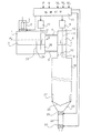
本発明は、ボールを形成しようとする材料を融合槽内に供給する手段と、溶解した材料を受け入れるために融合槽と通じている第2の槽と、第2の槽内に入っている溶解した材料から、少なくとも一つのオリフィスを通じて射出流を形成する手段と、射出流を小滴に変換するために、振動をオリフィスへ伝達する振動手段と、オリフィスの流出口に配置され、不活性ガスが充填されており、重力によって落下する小滴がボールを形成するように凝固する冷却塔と、冷却塔の下端部でボールを受ける手段とを備える球状ボールを製造する装置に関する。
【0002】
【従来の技術】
多くの産業界、例えば冶金、化学肥料、食品あるいは医薬業等に適用される多数の方法及び粒状化装置がある。それらは全て、大気中又は中性ガス下で、低粘度、良好な表面張力、良好なオリフィス中の流動性を有し、かつ冷却によって凝固しやすい、溶解した材料をボールに変換しようとするものである。
【0003】
具体的には、米国特許第4428894号に対応する、国際特許出願WO−A−8101811は、0.1〜5mmの直径の金属製粒状物を溶解金属槽で製造する方法及び装置について記載している。この既知の方法によれば、溶解した金属の射出流が形成され、それが、該射出流を個々の液滴に分割するために、振動するオリフィスを通過し、該液滴が、該液滴を冷却によって凝固させて粒状物にするために、重力により、不活性ガスの雰囲気を通って該射出流から落下する。
【0004】
しかし、実際には、例えば、良好な産出量で、非常に良好な表面状態を有する均一な大きさのボールを大規模に製造することができる方法及び口径測定粒状化装置はほとんどない。また、この種の技術によって粒状化されたどのような材料(有機生産物、金属等)であっても、一定の割合の生産物が、非常に変形したボール、あるいはダンベルと称される組のような、2つがくっついたボールからなることがたびたび起きる。
【0005】
さらに、ある用途の場合、表面欠陥がなく、非常に正確な粒度を有するボール、より具体的には微少ボールを製造することが必要である。これらの微少ボールは、好ましくは、均一な直径を有するだけでなく、完全に球状かつ分離されていなければならない。機械産業においては、ボールが、比較的高い硬度を有する材料から成る場合、一般に、ホッパー、ローラ等から成る選別装置又は分類装置が使用される。これは、特に、ベアリングやペン等のためのボールの場合である。従って、ボールは、その表面に傷などを付けることなく、衝撃や摩擦に耐えることになる。逆に、ある場合においては、球形度及びボールの表面状態は、上記選別装置によって変更されるべきではない。
【0006】
これは特に、例えばBGA(ボールグリッドアレイ)型のケーシングのための接続部を形成するために電子機器で使われる溶解合金ボールの場合である。さらに、溶解合金に用いられる金属は柔らかい金属であり、そのような金属から成るボールの表面状態は、容易に改変することができる。
【0007】
【発明が解決しようとする課題】
本発明の目的は、表面欠陥がないボールを得ることである。特に、ボールは、良好な表面状態で、酸化していない、完全に球状でなければならない。ボールの成分は、各製造バッチで非常に安定していなければならず、また許容誤差は、粒度測定に関して非常に狭くなる。
【0008】
【課題を解決するための手段】
本発明によれば、この目的は、上記装置が、融合槽内に流出チャンバを備え、かつ該流出チャンバ内に入っている溶解した材料を第2の槽内へ移送する前に超音波攪拌する手段を備え、冷却塔内の不活性ガスが予め設定された量の酸素を含有するということによって達成される。
【0009】
本発明の展開によれば、ボールを受ける手段は、衝撃吸収手段から成る。該衝撃吸収手段は、好ましくは、ポリアミドをベースとしたワイヤから成り、冷却塔内のボールの軌跡と略45°の角度を形成するブラシを備える。また、ブラシの上の、冷却塔の内壁の下部周辺に、クロスローラを配置することができる。
【0010】
好適な実施の形態によれば、上記装置は、冷却塔の出口に、ボールの周期的抜き取りのための手段と、ボールをそのサイズに関する3つの種類に分類する手段から成る口径測定手段とを備える。上記装置はまた、各抜き取りシーケンスにおいて得られた各種類のボールの組を計量する手段と、該計量手段によって与えられた情報に基づいて予め設定された基準内のボールの割合を計算する手段と、該割合に関連して振動手段の周波数を調整する手段とを備えてもよい。
【0011】
本発明の他の目的は、完全に球状でない全てのボールをはじくために、均一な径のボールを分類することが可能な球状ボールの選別装置を用いて、球状ボールを製造する装置を提供することである。
【0012】
本発明によれば、この目的は、選別装置が、予め設定された寸法の間隔で離間した、一連の傾斜面のうちの最初の傾斜面上にボールを供給する手段を備え、少なくとも最初の傾斜面が、ボールの移動方向に、その粗さが次に続く傾斜面の粗さよりも粗い表面を有するという事実によって達成される。
【0013】
好適な実施の形態によれば、最初の傾斜面上にボールを供給する手段は、回転面と、停止手段と、停止手段に載っているボールを回転面から急速にはね出すはね出し手段とを備える。
【0014】
上記はね出し手段は、好ましくは、横方向の往復動で動き、湾曲部に沿って均一に配置された複数の空気エジェクタを備えた中空の湾曲部から成る。
【0015】
本発明の他の特徴によれば、最初の傾斜面上にボールを供給する手段は、該傾斜面及び面上のボールの回転方向と反対の回転方向と同じ方向に傾斜面を有するコンベヤベルトを備える。
【0016】
本発明の別の目的は、くっついたボールの排除に関する。
【0017】
本発明の展開によれば、この別の目的は、選別装置が、傾斜面の下流側に、傾斜軸周りの回転動で動き、その大きさが、分離されたボールを回転できるようにし且つくっついた一組のボールが回転するのを防ぐ長手方向の溝を備える歯状突起のある車輪を備えるという事によって達成される。
【0018】
本発明の他の効果及び特徴は、それに限定されない、例示目的のために示す、添付図面に提示された、本発明の特定の実施の形態の以下の説明からより明白になるであろう。
【0019】
【発明の実施の形態】
図1に係る装置は、適当な手段(図示せず)によって加熱される槽又は溶解ポット1を備え、ボールにする予定の材料を、供給ロック2によって、固形の合金の形で投入することができる。ビレット、インゴット又は棒3の形で投入された材料は、融合槽内で溶解される。適当な手段(図示せず)によって加熱された第2の槽又は粒状化ポット4は、その底部において、少なくとも一つの移送管5によって溶解ポット1の底部に接続されている。連結管6は、溶解した材料の上部の上のガス状雰囲気の圧力Pが両ポット内で等しくなるように、溶解した材料のレベル7の上で、両ポット1、4の上部を接続する。さらに、ポット1、4内の溶解した材料のレベルを一定に維持するために、レベル検知器(図示せず)がインゴットの供給装置に接続されている。
【0020】
粒状化ポット4は、一般に、溶解した合金がその中を射出流の形で流れる、予め設定された径の少なくとも一つのオリフィス8をその下部に備えている。粒状化ポット4の蓋部に取付けられた振動器9は、垂直方向の上下動で動く振動パレット10によって振動をオリフィス8に伝達する。振動パレット10が、粒状化ポット4の蓋部12から狭い通路を貫通する金属製ロッド11によって、例えば電磁型の振動器9と接続されていることは既知である。振動器の周波数は、200Hz〜10,000Hz、好ましくは、200Hz〜6,000Hzの範囲である。
【0021】
材料、例えば融合する金属合金は、溶解ポット1内で溶解した後、液状で、移送管5によって粒状化ポット4内に移送される。溶解した材料の上部の上のガス状雰囲気(例えば窒素)の圧力Pは、予め設定された速度(好ましくは、オリフィスの口径にしたがって0.5〜5m/sの間)を、粒状化ポットの下部における各オリフィス8を通り抜ける溶解した材料の射出流に伝えるために、制御回路13により永続的かつ規則的に測定される。振動するパレット10の振動は、オリフィス8から層流の射出流14に伝えられる。そして、図2に示すように、射出流14は、その直径が主としてオリフィス8(好ましくは、80〜800μm)の直径Dによって決定される小滴15に分割される。該小滴は重力によって、小滴が球状ボールを形成するように凝固する不活性ガスが充填されている冷却塔16内に落下する。30〜100mbarsの範囲、好ましくは50mbars程度で±1mbarsに完璧に調整された圧力下でヘリウムを使用すると、例えば2〜3秒内にボールを急速に冷却することができる。冷却塔16の高さは、一般に数m、例えば7mである。その他の不活性も使用することができる。しかし、窒素又はアルゴンを使用すると、略2倍の高さの冷却塔が必要となる。
【0022】
円形で直径Dの一つ又は数個のオリフィス8は、好ましくは、オリフィスを通り抜け、その表面張力が粒状化される材料の表面張力を相殺する溶解した材料によって濡れ性がない材料で形成されている。具体例として、オリフィス8は、サファイア又はルビーで形成されている。図2、3に示した特定の実施の形態においては、粒状化ポット4の壁部17は、ステンレス鋼で形成され、かつその下部に、その中に少なくとも一つのオリフィス8が形成されている、サファイア又はルビーから成るインサート18を備えている。各オリフィス8は、直径D以下の高さHの垂直壁によって表わされている。好適な実施の形態においては、D=450μmでH=190μmである。図2及び図3の好適な実施の形態においては、オリフィス8は、インサート18の傾斜又は湾曲壁部19によって描かれているその下部においてじょうご状に開いている。
【0023】
本発明によれば、溶解ポット1は、溶解した材料が超音波攪拌される流出チャンバ20を備えている。この攪拌は、流出チャンバ20内に含まれている溶解した材料内に浸され、かつ振動装置22、例えば圧電型の振動装置によって垂直方向に往復動する棒21によって実現することができる。例えば20〜30kHzの範囲での超音波攪拌は、ボールの表面状態を実質的に改善できるようにする。この攪拌は、オリフィス8を通過する溶解した材料の流れを妨げるので、粒状化ポット4内では実行できない。この攪拌は、粒状化ポット4内に注入される前に、溶解した材料の均質化を本質的に引き起こす。この攪拌は、流出チャンバ20内のみ、例えば、粒状化ポット4への溶解した材料の出口の近傍に配置され、かつその中で材料全体がすでに溶解している溶解ポット1の一部においてのみ行われる。
【0024】
図4に示す好適な実施の形態においては、流出チャンバ20は、溶解ポット1の容積の約20%よりも小さい容積を有する。湾曲することができる壁部23は、溶解ポット1の内側で流出チャンバ20を表わす。該壁部23は、溶解した材料が流出チャンバに入ることができるようにするための数mm(例えば5mm)の通路24を、その下部に備えている。
【0025】
粒状化ポット4内への注入前の溶解した材料の均質化は、同時に、オリフィスを塞ぐことは言うまでもなく、溶解した材料の流れのオリフィス8の通過を妨げる、結晶化の兆しの分散及び溶解した材料内の微少不純物の浮遊を引き起こす。
【0026】
この超音波攪拌を含まない装置は、電子機器の使用において不適当な様々な大きさ及び深さのくぼみをその表面に備えたボールを形成してしまうことに注意すべきである。本発明に係る超音波攪拌は、このタイプの欠陥を大幅に少なくすることができるようにするだけでなく、通常、欠陥を完全に消滅させることができるようにする。超音波攪拌は、永続的に行うことができる。また、制御回路13によって断続的に行うことも可能である。溶解した材料は流出チャンバ20から粒状化ポット4へ継続的に移送することができるのに対して、均質化の効果は、溶解した材料がオリフィス8を通過する前に、一定時間、具体的には30mnまで、粒状化ポット4内で待機していなければならなくても、ボールの表面状態に反映される。
【0027】
得られたボールの表面状態を改善できるようにするその他の方法は、冷却塔16内に含まれるガスの性質に影響を及ぼすことである。実際に、該ガスの性質は、ボールの球形度、迅速な凝固及び表面状態にとって大変重要である。本発明の別の態様によれば、予め設定された量の酸素、好ましくは数ppm、例えば15〜150ppm程度の酸素が冷却塔16の不活性ガスに注入される。冷却塔の不活性ガスに酸素が含まれていない場合、ボールは、酸素が不活性ガスに注入されていない場合に消滅する微少切子面をその表面に呈する。しかし、酸素の量が多すぎる場合には、ボールは所要の球形度を有しない。
【0028】
溶解した材料の流出チャンバ内での超音波均質化と、冷却塔内への予め設定された量の酸素の注入との組合せは、球状ボール、特に融合する金属合金から形成された微少ボールの表面状態を強化できるようにする。
【0029】
冷却塔16の下端部でのボールの受け取りは、好ましくは、ボールの表面状態の変質を避けるように減衰される。多くの既知の装置においては、ボールは液状で受け取られる。このタイプの受け取りは、後の工程でボールの乾燥を要求されるという欠点を有する。
【0030】
図5、6に示した好適な実施の形態においては、ブラシ25によって衝撃が本質的に吸収される。このことは、受け取りゾーンにおけるいかなる液体も排除できるようにするので、プロセスの全ての段階が乾燥状態で実行される。各ブラシ25はポリアミドをベースとしたワイヤから成り、その一端は冷却塔の内壁部の下方垂直部と受け取り円錐体部26との接合部の近傍に固定されている。該ワイヤは冷却塔内のボールの軌跡と約45°、例えば、鉛直に対して実質的に45°の角度を形成する。特定の実施の形態においては、2つ一組で対向した、約10cm幅の4つのブラシ25が冷却塔の周囲に沿って配置されているので、2つの対向するブラシのワイヤの自由端は互いに接している。ワイヤの直径は、ボールの直径より小さい。ブラシの柔軟性は、ボールの表面状態を変質させることなく、一旦衝撃が吸収されると、ボールを通過させる。
【0031】
受け取り円錐体部26に到達する前の、ブラシ25によるボールの衝撃吸収は、ブラシの上の、冷却塔の内壁の下方周辺部に配置された、好ましくはポリアミドをベースとするクロスから成るローラ27を用いることによって完全なものとすることができる。ローラ27は垂直に配置することができ(図5、6)、ブラシのすぐ上に位置している領域を覆う。従って、ブラシ25に対して跳ね返るボールによって引き起こすことが可能な、冷却塔の内壁に対するボールのいかなる衝撃も減衰される。
【0032】
冷却塔の受け取り円錐体部26は、両方共制御回路13によって操作される流入弁29及び流出弁30を備えたロック28によって延長されている。該ロックは、受け取り円錐体部26内に集積したボールの周期的な抜き取りができるようにする。その後、ボールは口径測定装置へ移送される。
【0033】
図7の特定の実施の形態においては、(一般に100〜300g/mnの間で)抜き取られたボールは、予め設定された基準よりも大きなサイズのボールを保持するふるい31上に、重力によって落下する。上方のふるい31を通過したボールは、第1のじょうご部32を通って、小さすぎるボールを通過させる下方のふるい33上に落下する。そしてボールは、第2のじょうご部34を通って第1のタブ35内に落下する。基準に一致するボールは下方のふるい33内に保持されている。ふるい31及び33をひっくり返すことにより、大きすぎるボール及び基準を満たすボールは、それぞれ第3及び第4のじょうご部36、37を通って、それぞれ第2及び第3のタブ38、39内に落下する。従って、ボールは、そのサイズに関連して3つの種類、すなわち、タブ39内への基準を満たすボールと、第1のタブ35内への小さ過ぎるボールと、第2のタブ38内への大き過ぎるボールとに分類される。
【0034】
それぞれ第1、第2及び第3のタブ35、38及び39の下に配置された第1、第2及び第3の重量計40、41及び42は、それぞれ第1、第2及び第3のタブ内に集められたボールの重量を表わす信号M1、M2、M3を各抜き取りサイクルの間、制御回路13へ供給する。制御回路13は、この計量情報に基づいて、基準に従い、かつ産出物を100%近くに維持するための粒状化パラメータに基づいてふるまう抜き取ったボールの割合を計算する。好適な実施の形態においては、制御回路13は、振動器9の周波数を調節及び調整する。振動器9の周波数が増加すると、ボールのサイズが小さくなる。具体的には、振動器の定格周波数が500Hzの場合、振動は±5Hzになる。
【0035】
本発明はまた、完全な球形でない全てのボールをはじくために、均一な直径のボールを分類することができる球状ボールの選別装置を用いて球状ボールを製造する装置に関する。
【0036】
種々の直径から成り、重大な変形を呈する球状生産物が傾斜面を用いて分類され、ボールが、異なるボールによって到達する速度に関して分類されることは既に提案されてきた。
【0037】
この種の分類法は、分類操作の前に、全てのボールが狭い許容差内で既に同じ直径を有するが、その球形度が比較的狭い範囲で変化するボールの分類に適している。従って、分類操作の目的は、完全に球形でなく、かつその表面状態が完璧でない全てのボールを排除することである。
【0038】
図8に示した実施の形態においては、装置は、分類すべきボールが入っている、ホッパー43の形のタブを備える。このようなタブは、上述した球状ボールを製造する装置の流出口に配置されている。ボールは、一連の傾斜面44a、44b、44c、44d上を通過する。各傾斜面は、直前の傾斜面よりわずかに下に位置し、水平間隔e1は2つの連続する傾斜面を分離している。傾斜面間の隙間間隔は、連続する傾斜面の間に落ちることなく、次の傾斜面上へ通過するために十分な速度に達することなく、傾斜面の端部に達したボールを排除できるようにする。
【0039】
全ての傾斜面は、同じでない表面状態を有しており、その表面は、分類すべきボールの各直径に対して完全に制御されている。ボールの速度は、何種類かの負荷、重力、摩擦負荷、空気力学的負荷、回転面との相互作用等の影響の組合せによる。傾斜面は、好ましくは、その表面が、少なくとも最初の傾斜面がより大きな、ボールの移動方向に制御された粗さを有する金属シートから成る。最初の傾斜面44aの粗さは、表面欠陥を有するボールをより著しく減速させるために、次に続く傾斜面のそれよりも大きい。このようなボールの表面上での軌跡は、複雑な様相を呈するので、欠陥は明らかになくなり、ボールは減速しようとし、例えばボールを傾斜面44a、44b間に落下させる。制御された粗さの存在は、摩擦を増加させず、ボールの表面状態の劣化を引き起こすが、非平坦性に関してボールの軌跡を動揺させるかもしれない。このことは、申し分のない球状ボールがより直進的な軌跡をたどることができるようにし、その結果高速の流出速度に達することができるようにする。
【0040】
要求された粗さを得るためには、傾斜面の表面は、適当な手段、例えば研磨、ショットピーニング又は他の機械的および/または化学的手段によって処理され、あるいは適切なコーティングにより覆われる。好適な実施の形態においては、最初の傾斜面44a、44bは、2番目の傾斜面に対して小さくすることができる高い粗さを呈する。最後の傾斜面44d、あるいは傾斜面44c及び44d両者は、完全に平滑な表面を有していてもよい。ボールの表面欠陥と傾斜面の表面状態との間の相互作用は、欠陥のあるボールの速やかな排除を可能にする。
【0041】
各傾斜面の傾斜度及び連続する2つの傾斜面間の間隔は、良好な球形度を有するボールが、一つの傾斜面から次の傾斜面へ通過するのに十分な速度で傾斜面上を転がるように、ボールの直径に関連して決定される。各傾斜面は、その上流部に、傾斜面上でのボールの受け取り時に衝撃を減衰させ、ボールの跳返りを防ぐための上向きの湾曲部を備えている。
【0042】
具体例として、直径が一般に500μmよりも小さい、融合合金から成る微少ボールを選別するために、各傾斜面は、10〜15cm程度の長さLと、1m程度の幅とを水平方向に有する。連続する2つの傾斜面間の鉛直方向の間隔e2は、1cm以下にすることができるのに対して、水平方向の間隔e1は、1〜3cm程度にすることができる。傾斜面の数は、ボールのサイズに反比例し、好ましくは2〜5の範囲である。さらにボールは重ければ重いほど早く動く。従って、傾斜面の角度は、良好な選別ができるように小さくなければならない。
【0043】
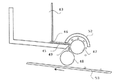
ホッパー43から来るボールは、ホッパー43の底部から伸びる、わずかに傾斜した回転面45によって最初の傾斜面44a上に供給される。ボールは、回転面上を転がる一層のボールを形成するために、重力の影響の下で、狭い通路46を通ってホッパー43の下部から出ていく。回転面45の自由端において、ボールはストッパ47に載っている。図8〜図9において、ストッパ47は、少なくとも回転面45の全幅を覆って、回転面45上のボールが流れる方向と直角に配置されたシリンダから成る。従って、ボールはストッパ47の手前で整列する。ボールの直径よりも小さい間隔が、回転面45の自由端をストッパ47から隔離している。
【0044】
ストッパ47の前で整列したボールは、回転面から急速にはね出される。このはね出しは、好ましくは、圧縮された乾燥空気又は不活性ガス(窒素、アルゴン等)の流れを継続的に循環させる中空管から成る湾曲部48によって実現される。湾曲部48は、回転面45の自由端の前方で、ストッパ47と平行に配置されている。該湾曲部は、回転面の自由端とストッパとの間に画定された間隔の方に向けられ、湾曲部48に沿って均一に配置され、ストッパ47の前に整列したボールの列を、好ましくは急速に浮揚させるために設けられたエジェクタを構成する複数のエアノズル49を備えている。
【0045】
ボールの急速なはね出しを確実にするために、湾曲部48は、回転面45上のボールの流れ(図10、12、13において左側から右側)の方向と直角な、横方向の往復動を有するジャッキ(図示せず)によって動く。湾曲部の往復動の間の2つの両端位置の場合の湾曲部48及び回転面45のそれぞれの位置をそれぞれ図12及び13に示す。回転面45は、少なくともその自由端に、均一な厚さで(図11)、上から見て三角形で、該回転面を幅が漸減する複数のレーン51に分割する障害物50を備えている。障害物50は、回転面の自由端において、ごくわずかにはみ出ている。回転面45の自由端と平行な、障害物50の三角形部分の底辺は、長さl1を有し、隣接する2つの障害物の頂点は距離l2(図12)だけ離れている。三角形の障害物50の底角は、湾曲部48の両端位置(図12及び13)におけるエアノズル49の移動の軌跡を描く。
【0046】
従って、湾曲部48が2つの両端位置のうちの一つにあるとき、道程の終端において、全てのエアノズル49は、障害物50の端部の下に配置されている。そして、エアノズル49を介して湾曲部48から出てきた空気の噴流は、障害物50の下に導かれ、回転面45上のレーン51内に配置されたボールをはね出すことができない。逆に、湾曲部48の移動の間、各レーンと関連してエアノズルから出てきた空気の噴流は、ストッパ47に載っているボールの列のはね出しを引き起こす。はね出しは、エアノズルの移動と歩調を合わせて漸進的である。両端部における湾曲部の休止時間は、断続的な急速なはね出しを得ることができるようにし、それによりボールの次の列のはね出しの前に、下流のスペースを完全に一掃し、かつボールの表面状態を変えそうなボール間の相互作用を制限する。従って、各回転ゾーン上にあるボールの量は規制かつ制限されている。
【0047】
好適な実施の形態8においては、上記障害物は、7つのレーン51で描かれている。障害物50の三角形の底辺の長さl1は、距離l2が130mm程度の場合、20〜30mm程度にすることができる。両端位置間の湾曲部の移動の継続時間は、例えば、1〜数秒(0.1〜1Hzの周波数)の範囲である。
【0048】
はね出されたボールは、コンベヤベルト53の傾斜面上のバッフル52によって方向付けられる。好ましくは湾曲したバッフル52は、ストッパ47と共に、回転面45、ストッパ47、湾曲部48及びバッフル52から成るアセンブリの下に配置されたコンベヤベルト53の傾斜面上に後に落下する、はね出されたボールのための通路を形成する。その上にはね出されたボールが落下するコンベヤベルトの表面は、傾斜面44a〜44dと同じ方向に傾斜している。コンベヤベルト53の回転方向は、コンベヤベルトの表面上のボールの回転方向の逆である(図8)。
【0049】
良好な球形度を有するボールは、コンベヤベルトの傾斜面上を第1の傾斜面44aの方へ転がる。コンベヤベルトの移動速度は、その傾斜面上をその移動の逆方向に転がる球状ボールが第1の傾斜面に達するように選択される。具体例として、コンベヤベルトの速度は、0.5〜5m/mn程度、好ましくは2m/mnにすることができる。コンベヤベルトは、最初の選別を行う。転がることができない、あるいはコンベヤベルトの傾斜面上を非常にゆっくりと転がる、大きな表面欠陥を有するボールあるいはくっついたボールは、コンベヤベルトによって後部へ排出されて第1のタブ54内に落下するのに対して、球形度を有するボールは、第1の傾斜面まで逆方向に転がる。
【0050】
最後の傾斜面44dの出口において、選別されたボールはホッパー55内に落下する。可動ストリップ56は、ホッパー内に収容される前のボールの最後の選別を行うために、最後の傾斜面44dとホッパー55との間に配置することができる。図8において、ストリップ56は、その一方がより速い速度のボールをホッパー56の方へ向け、その他方が、上方縁部の上流に落下するより速度の遅いボールを排出する、2つの壁部を連結する上方縁部を備える。
【0051】
上述した選別装置は、表面状態に関連して均一な直径の球状ボールを選別することができるようにする。完全な表面状態を有するボールのみがホッパー55に到達する。しかし、くっついたボールがホッパー55に到達することがあるかもしれない。実際に、約100万個のボールのうち2、3組のくっついたボールがホッパーに到達する。これは、特に、くっついたボールの組60がコンベヤベルト53上、そして複数の傾斜面上に落下し、ボールの組の回転が減速しない場合であり、例えば、ボールの組の対称の長軸S(図15)がボールの移動の方向と完全に直角である場合である。また、ホッパー55に到達するかもしれないくっついたボールを排除するために、上記選別装置は、好ましくは、意味のある直径、例えば30cm程度の直径から成る、傾斜面の下流側に配置された歯状突起のある車輪57を備えている。
【0052】
図8の特定の実施の形態においては、じょうごの形をしたホッパー55は、ボールが歯状突起のある車輪57の上部上に流れることができるようにする。該車輪は、傾斜軸58周りの回転の遅い動きで動き、その寸法が、分離したボールが転がることができるようにし、かつくっついたボールの組60が回転するのを防ぐことができる、長手方向の溝59を備える(図14、15)。欠陥のないボールは、歯状突起のある車輪の溝59内を転がり、歯状突起のある車輪の下流側に配置された第2のタブ61内に集められる。溝内でブロックされたくっついたボールの組60は、軸58周りに歯状突起のある車輪と共に回転し、歯状突起のある車輪が半回転してボールの組60が位置している溝が、第3のタブ上の、歯状突起のある車輪の下部に達したときに、重力によって第3のタブ62内に落下する。
【0053】
突起のある車輪57は、好ましくは、数百の溝を備えている。溝59の底部は、ボールの直径の約1.2〜1.5倍の径を有しているため、くっついたボールの組は、溝と直角に位置することができず、かつ該溝内を転がることができない。ボールをより速く溝59内に落下させるために、歯状突起のある車輪の歯部の頂点は、好ましくは、わずかに丸みの付いた先端を有する鋭さとなっている。
【0054】
歯状突起のある車輪の外径と一致する、円弧状のバッフル(図示せず)を、ホッパー55の出口における狭い通路の場合の障壁として作用させるために、溝59と直角に配置することができる。
【0055】
本発明は、提示した特定の実施の形態に限定されない。特に、オリフィス8の数及び配置は、図示したのと異ならせることができる。同様に、冷却塔の流出口におけるボールの分類及び計量は、基準を満たすボールをその他のボールと分離し、要求された情報を供給することができる他の適当な手段によっても実行することができる。ふるい、じょうご及びタブの数及び配置も提示したものと異ならせることができる。制御回路13は、好ましくは、上記装置によって製造されたボールに影響を与えそうな様々なパラメータを表わす信号を受け取り、該パラメータに影響を及ぼす様々な部材を制御する。従って、該制御回路は、適切な手段を介して、ポット1、4及び冷却塔16内の圧力P及び温度θの測定信号である、信号M1、M2及びM3を完全に掌握して受け取る。また該制御回路は、供給ロック2からの材料3の供給、ロック28によるボールの抜き取り、振動装置22、振動器9、ポット1、4の加熱、ポット及び冷却塔内部の気圧及び冷却塔内に含まれる酸素の量を制御する。
【0056】
選別装置の形状、大きさ、配置及び数は、選別すべきボールの大きさに適応させることができる。ストッパ47は円筒形である必要はない。鋭い縁部はボールの表面状態を損傷するかもしれないので、湾曲した形状がやはり有利である。
【図面の簡単な説明】
【図1】本発明に係る装置の特定の実施の形態の断面略図である。
【図2】図1に係る装置の粒状化ポットの底部の詳細を示す図である。
【図3】図2に係る粒状化ポットの流出オリフィスの特定の実施の形態の詳細を示す図である。
【図4】図1に係る溶解ポットの線A−Aについての断面図である。
【図5】図1に係る装置の冷却塔の底部に配置された衝撃吸収装置の特定の実施の形態を示す図である。
【図6】図5の衝撃吸収装置の線B−Bについての断面図である。
【図7】図1に係る装置の冷却塔の出口に配置された口径測定及び計量装置の特定の実施の形態の略図である。
【図8】本発明に係る装置の選別装置の特定の実施の形態の略図である。
【図9】図8に係る選別装置の傾斜面の上流側に配置された装置の部分の特定の実施の形態を詳細に示す側面図である。
【図10】図8に係る選別装置の傾斜面の上流側に配置された装置の部分の特定の実施の形態を詳細に示す底面図である。
【図11】回転面の自由端から見た、図10に係る装置のホッパの流出回転面の特定の実施の形態を示す図である。
【図12】湾曲部の2つの両端位置の場合の、可動湾曲部の位置及びホッパの流出回転面の位置を示す図である。
【図13】湾曲部の2つの両端位置の場合の、可動湾曲部の位置及びホッパの流出回転面の位置を示す図である。
【図14】図8に係る選別装置の歯状突起のある車輪の断面図である。
【図15】図14に係る歯状突起のある車輪の溝の内部にブロックされた一組のボールの位置を示す図である。
【符号の説明】
1 融解ポット
2 供給ロック
3 棒
4 粒状化ポット
5 移送管
6 連結管
7 材料のレベル
8 オリフィス
9、10、11 振動手段
12 蓋部
13 制御回路
16 冷却塔
20 流出チャンバ
21、22 超音波攪拌
23 壁部
24 通路
25 ブラシ
26 受け取り円錐体部
27 ローラ
28 ロック
29 流入弁
30 流出弁
M1、M2、M3 情報[0001]
BACKGROUND OF THE INVENTION
The present invention includes means for supplying a material into which the balls are to be formed into a fusion vessel, a second vessel communicating with the fusion vessel to receive the dissolved material, and a dissolution contained within the second vessel. Means for forming an injection flow from at least one orifice through the material, vibration means for transmitting vibration to the orifice to convert the injection flow into droplets, and an inert gas disposed at the outlet of the orifice. The present invention relates to an apparatus for producing a spherical ball comprising a cooling tower that is filled and solidifies so that droplets falling by gravity form a ball, and means for receiving the ball at the lower end of the cooling tower.
[0002]
[Prior art]
There are a number of methods and granulation equipment applied in many industries such as metallurgy, chemical fertilizer, food or pharmaceutical industry. They all attempt to convert dissolved materials into balls that have low viscosity, good surface tension, good orifice fluidity in air or neutral gas, and are easy to solidify on cooling It is.
[0003]
Specifically, international patent application WO-A-8101811, corresponding to US Pat. No. 4,428,894, describes a method and apparatus for producing 0.1-5 mm diameter metal granules in a molten metal bath. Yes. According to this known method, a molten metal injection stream is formed, which passes through an oscillating orifice to divide the injection stream into individual droplets, which droplets are In order to solidify by cooling into granules, it falls from the injection stream through the inert gas atmosphere by gravity.
[0004]
In practice, however, there are few methods and caliber granulation devices that can produce, for example, large-sized balls with a good yield and a very good surface condition. Also, whatever material (organic product, metal, etc.) granulated by this kind of technology, a certain percentage of the product is a highly deformed ball or a set of dumbbells. It often happens that the ball consists of two sticking balls.
[0005]
In addition, for certain applications, it is necessary to produce balls that are free of surface defects and have a very precise particle size, more specifically, microballs. These microballs should preferably not only have a uniform diameter but also be completely spherical and separated. In the machine industry, when a ball is made of a material having a relatively high hardness, a sorting device or a sorting device including a hopper, a roller, or the like is generally used. This is especially the case for balls for bearings, pens and the like. Therefore, the ball withstands impact and friction without damaging its surface. Conversely, in some cases, the sphericity and the surface condition of the ball should not be changed by the sorting device.
[0006]
This is particularly the case for molten alloy balls used in electronic equipment to form connections for eg BGA (ball grid array) type casings. Furthermore, the metal used for the molten alloy is a soft metal, and the surface state of a ball made of such a metal can be easily modified.
[0007]
[Problems to be solved by the invention]
The object of the present invention is to obtain a ball free of surface defects. In particular, the balls must be perfectly spherical, in good surface condition, not oxidized. The components of the ball must be very stable with each production batch and the tolerance is very narrow with respect to particle size measurement.
[0008]
[Means for Solving the Problems]
According to the invention, the object is that the device comprises an outflow chamber in the fusion tank and is ultrasonically agitated before transferring the dissolved material contained in the outflow chamber into the second tank. Means and is achieved by the fact that the inert gas in the cooling tower contains a preset amount of oxygen.
[0009]
According to a development of the invention, the means for receiving the ball comprises an impact absorbing means. The impact absorbing means is preferably made of a polyamide-based wire and includes a brush that forms an angle of approximately 45 ° with the trajectory of the ball in the cooling tower. Moreover, a cross roller can be arrange | positioned around the lower part of the inner wall of a cooling tower on a brush.
[0010]
According to a preferred embodiment, the device comprises at the outlet of the cooling tower a means for periodic withdrawal of the balls and a calibration means comprising means for classifying the balls into three types relating to their size. . The apparatus also includes means for weighing each type of ball set obtained in each sampling sequence, and means for calculating a proportion of balls within a preset reference based on information provided by the weighing means; And a means for adjusting the frequency of the vibration means in relation to the ratio.
[0011]
Another object of the present invention is to provide an apparatus for producing a spherical ball using a spherical ball sorting apparatus capable of classifying balls of uniform diameter in order to repel all balls that are not perfectly spherical. That is.
[0012]
According to the invention, the object is to provide that the sorting device comprises means for supplying a ball onto a first inclined surface of a series of inclined surfaces spaced apart by a predetermined dimension, at least the first inclined surface. The surface is achieved by the fact that in the direction of movement of the ball, its surface has a surface that is rougher than the roughness of the subsequent inclined surface.
[0013]
According to a preferred embodiment, the means for supplying the ball on the first inclined surface comprises a rotating surface, a stopping means, and a splashing means for rapidly ejecting the ball placed on the stopping means from the rotating surface. With.
[0014]
The spilling means preferably comprises a hollow bend with a plurality of air ejectors that move in a reciprocating motion in the lateral direction and are uniformly arranged along the bend.
[0015]
According to another feature of the invention, the means for supplying the ball on the first inclined surface comprises a conveyor belt having an inclined surface in the same direction as the rotating direction opposite to the rotating direction of the ball on the inclined surface and the surface. Prepare.
[0016]
Another object of the invention relates to the elimination of stuck balls.
[0017]
According to the development of the invention, this further object is that the sorting device moves on the downstream side of the inclined surface with a rotational movement around the inclined axis, the size of which allows the separated ball to rotate and sticks. This is accomplished by providing a toothed wheel with a longitudinal groove that prevents a set of balls from rotating.
[0018]
Other advantages and features of the present invention will become more apparent from the following description of specific embodiments of the invention presented in the accompanying drawings, which are given by way of illustration and not limitation.
[0019]
DETAILED DESCRIPTION OF THE INVENTION
The apparatus according to FIG. 1 comprises a bath or
[0020]
The
[0021]
The material, for example, the metal alloy to be fused, is melted in the
[0022]
One or
[0023]
According to the invention, the
[0024]
In the preferred embodiment shown in FIG. 4, the
[0025]
The homogenization of the melted material before pouring into the
[0026]
It should be noted that this apparatus that does not include ultrasonic agitation creates balls with various sizes and depth indentations that are inappropriate for use in electronic equipment. The ultrasonic agitation according to the invention not only makes it possible to greatly reduce this type of defect, but also usually makes it possible to eliminate the defect completely. Ultrasonic stirring can be performed permanently. It can also be performed intermittently by the
[0027]
Another way to be able to improve the surface condition of the balls obtained is to influence the nature of the gas contained in the
[0028]
The combination of ultrasonic homogenization in the outflow chamber of the melted material and the injection of a preset amount of oxygen into the cooling tower is the surface of a spherical ball, especially a microball formed from a fusing metal alloy. Allow to strengthen the state.
[0029]
The receipt of the ball at the lower end of the
[0030]
In the preferred embodiment shown in FIGS. 5 and 6, the shock is essentially absorbed by the
[0031]
The impact absorption of the ball by the
[0032]
The receiving
[0033]
In the particular embodiment of FIG. 7, the extracted ball (generally between 100-300 g / mn) falls by gravity onto a
[0034]
The first, second and third weigh scales 40, 41 and 42 respectively disposed under the first, second and
[0035]
The invention also relates to an apparatus for producing a spherical ball using a spherical ball sorting device that can classify balls of uniform diameter to repel all non-spherical balls.
[0036]
It has already been proposed that spherical products consisting of various diameters and exhibiting significant deformations are classified using inclined surfaces and the balls are classified in terms of the speed reached by the different balls.
[0037]
This type of classification is suitable for classification of balls where all balls already have the same diameter within a narrow tolerance, but their sphericity varies within a relatively narrow range, prior to the classification operation. The purpose of the classification operation is therefore to eliminate all balls that are not perfectly spherical and whose surface condition is not perfect.
[0038]
In the embodiment shown in FIG. 8, the device comprises a tab in the form of a
[0039]
All inclined surfaces have a surface state that is not the same, and the surface is completely controlled for each diameter of the ball to be classified. The speed of the ball depends on a combination of effects such as several types of loads, gravity, friction loads, aerodynamic loads, interaction with the rotating surface, and the like. The inclined surface preferably consists of a metal sheet whose surface has a controlled roughness in the direction of movement of the ball, at least with a larger initial inclined surface. The roughness of the first
[0040]
In order to obtain the required roughness, the surface of the inclined surface is treated by suitable means such as polishing, shot peening or other mechanical and / or chemical means, or covered with a suitable coating. In a preferred embodiment, the first
[0041]
The slope of each slope and the spacing between two successive slopes is such that a ball with good sphericity rolls on the slope at a speed sufficient to pass from one slope to the next. Thus, it is determined in relation to the diameter of the ball. Each inclined surface is provided with an upwardly curved portion at its upstream portion for attenuating an impact when the ball is received on the inclined surface and preventing the ball from rebounding.
[0042]
As a specific example, each inclined surface has a length L of about 10 to 15 cm and a width of about 1 m in the horizontal direction in order to select fine balls made of a fusion alloy whose diameter is generally smaller than 500 μm. The vertical interval e2 between two continuous inclined surfaces can be 1 cm or less, while the horizontal interval e1 can be about 1 to 3 cm. The number of inclined surfaces is inversely proportional to the size of the ball and is preferably in the range of 2-5. The heavier the ball, the faster it moves. Therefore, the angle of the inclined surface must be small so that good sorting is possible.
[0043]
Balls coming from the
[0044]
The balls aligned in front of the
[0045]
In order to ensure rapid splattering of the ball, the
[0046]
Accordingly, when the
[0047]
In the
[0048]
The ejected ball is directed by a
[0049]
Balls with good sphericity roll on the inclined surface of the conveyor belt towards the first
[0050]
The sorted balls fall into the
[0051]
The sorting device described above enables sorting of spherical balls of uniform diameter in relation to the surface condition. Only balls having a complete surface condition reach the
[0052]
In the particular embodiment of FIG. 8, a funnel-shaped
[0053]
The protruding
[0054]
An arcuate baffle (not shown) that matches the outer diameter of the toothed wheel may be placed at right angles to the
[0055]
The present invention is not limited to the specific embodiments presented. In particular, the number and arrangement of the
[0056]
The shape, size, arrangement and number of sorting devices can be adapted to the size of the balls to be sorted. The
[Brief description of the drawings]
FIG. 1 is a schematic cross-sectional view of a particular embodiment of an apparatus according to the present invention.
FIG. 2 shows details of the bottom of the granulation pot of the apparatus according to FIG.
3 shows details of a specific embodiment of the outlet orifice of the granulation pot according to FIG.
4 is a sectional view taken along line AA of the melting pot according to FIG. 1;
FIG. 5 is a diagram showing a specific embodiment of an impact absorbing device located at the bottom of the cooling tower of the apparatus according to FIG. 1;
6 is a cross-sectional view taken along line BB of the shock absorbing device of FIG.
7 is a schematic illustration of a particular embodiment of a calibration and metering device located at the outlet of the cooling tower of the apparatus according to FIG.
FIG. 8 is a schematic representation of a specific embodiment of a sorting device for a device according to the present invention.
9 is a side view showing in detail a specific embodiment of the part of the device arranged upstream of the inclined surface of the sorting device according to FIG. 8;
10 is a bottom view detailing a particular embodiment of the part of the device arranged upstream of the inclined surface of the sorting device according to FIG. 8;
11 shows a specific embodiment of the outflow rotation surface of the hopper of the device according to FIG. 10 as seen from the free end of the rotation surface.
FIG. 12 is a diagram showing the position of the movable bending portion and the position of the outflow rotation surface of the hopper in the case of two end positions of the bending portion.
FIG. 13 is a diagram showing the position of the movable bending portion and the position of the outflow rotation surface of the hopper in the case of two end positions of the bending portion.
14 is a sectional view of a wheel having a tooth-like projection of the sorting apparatus according to FIG. 8;
15 is a diagram showing the position of a set of balls blocked in the groove of the wheel having the tooth-like projections according to FIG. 14;
[Explanation of symbols]
1 Melting pot
2 Supply lock
3 sticks
4 Granulation pot
5 Transfer pipe
6 Connecting pipe
7 Material level
8 Orifice
9, 10, 11 Vibration means
12 Lid
13 Control circuit
16 Cooling tower
20 Outflow chamber
21, 22 Ultrasonic stirring
23 Wall
24 passage
25 brushes
26 Receiving cone
27 Laura
28 lock
29 Inlet valve
30 Outflow valve
M 1 , M 2 , M 3 information
Claims (19)
溶解した材料を受け入れるために融合槽(1)と通じている第2の槽(4)と、
第2の槽内に入っている溶解した材料から、少なくとも一つのオリフィス(8)を通じて射出流(14)を形成する手段と、
射出流(14)を小滴(15)に変換するために、振動をオリフィス(8)へ伝達する振動手段(9、10、11)と、
オリフィス(8)の流出口に配置され、不活性ガスが充填されており、重力によって落下する小滴(15)がボールを形成するように凝固する冷却塔(16)と、
冷却塔(16)の下端部でボールを受ける手段と、を備える球状ボールを製造する装置であって、
流出チャンバ(20)を融合槽(1)内に備え、かつ流出チャンバ(20)内に入っている溶解した材料を、第2の槽(4)へ送る前に超音波攪拌する手段(21、22)を備え、冷却塔(16)内に入っている不活性ガスが予め設定された量の酸素を含有していることを特徴とする装置。Means for feeding the material from which the balls are to be formed into the fusion vessel (1);
A second tank (4) in communication with the fusion tank (1) for receiving the dissolved material;
Means for forming an injection stream (14) from the dissolved material contained in the second tank through at least one orifice (8);
Vibration means (9, 10, 11) for transmitting vibrations to the orifice (8) to convert the injection stream (14) into droplets (15);
A cooling tower (16) disposed at the outlet of the orifice (8), filled with an inert gas, and solidified so that a drop (15) falling by gravity forms a ball;
Means for receiving a ball at the lower end of the cooling tower (16), and a device for producing a spherical ball comprising:
Means (21,) comprising an outflow chamber (20) in the fusion tank (1) and ultrasonically stirring the dissolved material contained in the outflow chamber (20) before being sent to the second tank (4) 22), characterized in that the inert gas contained in the cooling tower (16) contains a preset amount of oxygen.
Applications Claiming Priority (4)
| Application Number | Priority Date | Filing Date | Title |
|---|---|---|---|
| FR0110007A FR2827793B1 (en) | 2001-07-26 | 2001-07-26 | DEVICE FOR PRODUCING SPHERICAL BALLS |
| FR0110007 | 2001-07-26 | ||
| FR0110702 | 2001-08-10 | ||
| FR0110702A FR2828418B1 (en) | 2001-08-10 | 2001-08-10 | SPHERICAL BALL SELECTION DEVICE |
Publications (2)
| Publication Number | Publication Date |
|---|---|
| JP2003155505A JP2003155505A (en) | 2003-05-30 |
| JP4118626B2 true JP4118626B2 (en) | 2008-07-16 |
Family
ID=26213117
Family Applications (1)
| Application Number | Title | Priority Date | Filing Date |
|---|---|---|---|
| JP2002217045A Expired - Fee Related JP4118626B2 (en) | 2001-07-26 | 2002-07-25 | Spherical ball manufacturing equipment |
Country Status (11)
| Country | Link |
|---|---|
| US (1) | US6676890B2 (en) |
| EP (1) | EP1279450B1 (en) |
| JP (1) | JP4118626B2 (en) |
| KR (1) | KR100866294B1 (en) |
| CN (1) | CN1197674C (en) |
| AT (1) | ATE433815T1 (en) |
| CA (1) | CA2393862A1 (en) |
| DE (1) | DE60232622D1 (en) |
| MY (1) | MY127347A (en) |
| SG (1) | SG103876A1 (en) |
| TW (1) | TW577780B (en) |
Families Citing this family (24)
| Publication number | Priority date | Publication date | Assignee | Title |
|---|---|---|---|---|
| TW577780B (en) * | 2001-07-26 | 2004-03-01 | Ind Des Poudres Spheriques | Device for producing spherical balls |
| CN100395040C (en) * | 2005-12-08 | 2008-06-18 | 安徽精通科技有限公司 | Method for projecting and screening microelectronic-packed tin ball |
| WO2008044459A1 (en) * | 2006-10-11 | 2008-04-17 | Freund Corporation | Apparatus for manufacturing seamless capsule |
| JP5590501B2 (en) * | 2009-06-30 | 2014-09-17 | 日立金属株式会社 | Method for producing metal microspheres |
| ATE512189T1 (en) | 2009-09-30 | 2011-06-15 | Ems Patent Ag | METHOD FOR PRODUCING POLYMER PARTICLES |
| CN101844229B (en) * | 2010-03-24 | 2012-05-23 | 峨嵋半导体材料研究所 | Preparation method and production equipment of high-purity antimony particles |
| KR101745017B1 (en) * | 2011-12-05 | 2017-06-09 | 현대자동차주식회사 | Micro particle for thermal control material and, Device and method for manufacturing the same using ultrasonic high temperature vibration |
| US8486582B1 (en) * | 2012-09-24 | 2013-07-16 | Battelle Memorial Institute | Surface modification to prevent oxide scale spallation |
| CN105170022B (en) * | 2014-06-16 | 2017-11-10 | 新特能源股份有限公司 | Prilling granulator, the preparation method for preparing silicon tetrachloride catalytic hydrogenation catalyst and silicon tetrachloride catalytic hydrogenation method |
| DE102014110720A1 (en) * | 2014-07-29 | 2016-02-04 | Illinois Tool Works Inc. | soldering module |
| EP3000524A1 (en) * | 2014-09-29 | 2016-03-30 | Casale SA | Apparatus and method for prilling a liquid, preferably urea melt |
| TWI580509B (en) * | 2015-11-13 | 2017-05-01 | Spherical forming device | |
| CN105826207B (en) * | 2016-03-17 | 2018-05-04 | 大连理工大学 | A kind of core shell structure salient point preparation method and device |
| CN105655260B (en) * | 2016-03-17 | 2018-03-13 | 大连理工大学 | A kind of micro- interconnected salient points preparation method and device |
| JP6908706B2 (en) | 2016-08-24 | 2021-07-28 | 5エヌ プラス インコーポレイテッド | Low melting point metal or alloy powder atomizing manufacturing process |
| CN107570711A (en) * | 2017-07-11 | 2018-01-12 | 张家港创博金属科技有限公司 | A kind of pulse small hole gunite continuous high-efficient prepares the method and device of homogeneous spherical micro-particle |
| CN107377983A (en) * | 2017-08-04 | 2017-11-24 | 米亚索乐装备集成(福建)有限公司 | A kind of atomising device for preparing alloyed metal powder |
| CN110054396B (en) * | 2018-01-18 | 2021-10-15 | 宁波大学 | 2S2G chalcogenide glass microsphere manufacturing device |
| CN110090596B (en) * | 2018-01-30 | 2022-06-21 | 徐州市禾协肥业有限公司 | Inclined surface cooling granulation method and fertilizer granules thereof |
| KR102546750B1 (en) | 2018-02-15 | 2023-06-22 | 5엔 플러스 아이엔씨. | Method for producing atomization of high melting point metal or alloy powder |
| CN110465238B (en) * | 2019-08-27 | 2020-05-12 | 温州市阳安电子科技有限公司 | Carbide rotary atomizing granulator |
| CN111482615A (en) * | 2020-05-19 | 2020-08-04 | 郑州机械研究所有限公司 | Bottom leakage casting ultrasonic auxiliary system and bottom leakage casting system |
| CN114057487A (en) * | 2021-12-14 | 2022-02-18 | 中钢集团南京新材料研究院有限公司 | Isostatic pressing graphite preparation device and preparation method |
| CN116921231B (en) * | 2023-07-31 | 2024-01-23 | 苏州荣文西邻精密科技有限公司 | Sorting equipment |
Family Cites Families (15)
| Publication number | Priority date | Publication date | Assignee | Title |
|---|---|---|---|---|
| US171502A (en) | 1875-12-28 | Improvement in seed-separators | ||
| DE2253353A1 (en) | 1972-10-31 | 1974-07-11 | Knapsack Ag | SORTING DEVICE |
| FR2471827A1 (en) * | 1979-12-21 | 1981-06-26 | Extramet Sa | DEVICE FOR THE PRODUCTION OF UNIFORM METAL PELLETS |
| DE3538267A1 (en) | 1984-12-21 | 1986-06-26 | Rudolf Dipl.-Ing. 4048 Grevenbroich Koppatz | METHOD AND DEVICE FOR PRODUCING METAL GRANULES |
| JPS61221310A (en) * | 1985-03-26 | 1986-10-01 | Agency Of Ind Science & Technol | Method and apparatus for producing pulverous powder of metal or alloy or the like |
| FR2600000B1 (en) | 1986-06-13 | 1989-04-14 | Extramet Sa | PROCESS AND DEVICE FOR GRANULATING A MOLTEN METAL |
| US5229016A (en) * | 1991-08-08 | 1993-07-20 | Microfab Technologies, Inc. | Method and apparatus for dispensing spherical-shaped quantities of liquid solder |
| JPH11128845A (en) | 1997-10-30 | 1999-05-18 | Daizen:Kk | Sorter and sorting method |
| JP2000328111A (en) * | 1999-05-14 | 2000-11-28 | Nippon Steel Corp | Manufacture of small metal ball, and device therefor |
| JP2000328112A (en) | 1999-05-24 | 2000-11-28 | Sumitomo Metal Mining Co Ltd | Manufacture of solder ball and manufacturing device therefor |
| US6312498B1 (en) * | 1999-12-14 | 2001-11-06 | Mk Electron Co., Ltd. | Method of manufacturing solder balls |
| JP2001226706A (en) * | 2000-02-15 | 2001-08-21 | Hitachi Metals Ltd | Apparatus for manufacturing fine metallic ball |
| JP2001254108A (en) * | 2000-03-14 | 2001-09-18 | Hitachi Metals Ltd | Manufacturing method and manufacturing apparatus for fine metal ball |
| US6491737B2 (en) * | 2000-05-22 | 2002-12-10 | The Regents Of The University Of California | High-speed fabrication of highly uniform ultra-small metallic microspheres |
| TW577780B (en) * | 2001-07-26 | 2004-03-01 | Ind Des Poudres Spheriques | Device for producing spherical balls |
-
2002
- 2002-07-10 TW TW091115330A patent/TW577780B/en not_active IP Right Cessation
- 2002-07-12 SG SG200204286A patent/SG103876A1/en unknown
- 2002-07-15 US US10/194,011 patent/US6676890B2/en not_active Expired - Fee Related
- 2002-07-17 CA CA002393862A patent/CA2393862A1/en not_active Abandoned
- 2002-07-19 AT AT02354113T patent/ATE433815T1/en not_active IP Right Cessation
- 2002-07-19 MY MYPI20022736A patent/MY127347A/en unknown
- 2002-07-19 DE DE60232622T patent/DE60232622D1/en not_active Expired - Lifetime
- 2002-07-19 EP EP02354113A patent/EP1279450B1/en not_active Expired - Lifetime
- 2002-07-25 KR KR1020020043924A patent/KR100866294B1/en not_active IP Right Cessation
- 2002-07-25 JP JP2002217045A patent/JP4118626B2/en not_active Expired - Fee Related
- 2002-07-26 CN CNB021270422A patent/CN1197674C/en not_active Expired - Fee Related
Also Published As
| Publication number | Publication date |
|---|---|
| EP1279450B1 (en) | 2009-06-17 |
| KR100866294B1 (en) | 2008-10-31 |
| MY127347A (en) | 2006-11-30 |
| DE60232622D1 (en) | 2009-07-30 |
| JP2003155505A (en) | 2003-05-30 |
| ATE433815T1 (en) | 2009-07-15 |
| TW577780B (en) | 2004-03-01 |
| CN1400073A (en) | 2003-03-05 |
| US6676890B2 (en) | 2004-01-13 |
| SG103876A1 (en) | 2004-05-26 |
| US20030020213A1 (en) | 2003-01-30 |
| CN1197674C (en) | 2005-04-20 |
| EP1279450A1 (en) | 2003-01-29 |
| KR20030010532A (en) | 2003-02-05 |
| CA2393862A1 (en) | 2003-01-26 |
Similar Documents
| Publication | Publication Date | Title |
|---|---|---|
| JP4118626B2 (en) | Spherical ball manufacturing equipment | |
| US5183493A (en) | Method for manufacturing spherical particles out of liquid phase | |
| EP0996521B1 (en) | Apparatus and method for making uniformly sized and shaped spheres | |
| US3891730A (en) | Method for making metal powder | |
| CS238359B2 (en) | Melted material drops hardening acceleration method and equipment for execution of this method | |
| KR20170117530A (en) | Tundish arrangements and nozzles for granulation of molten material | |
| EP1707258A1 (en) | Fluid bed granulation process | |
| CN114160799B (en) | Metal powder manufacturing device and gas injector thereof | |
| US3054139A (en) | Method and apparatus for pelleting molten slag | |
| KR20030048132A (en) | Spheres and method of forming a plurality of spheres | |
| JP2703818B2 (en) | Method for spraying a melt and apparatus using the method | |
| JPS63503468A (en) | Molten material granulation equipment | |
| RU2020044C1 (en) | Method of producing metal granule from melted metal | |
| WO2013152946A1 (en) | A method for producing shot from melt, a device for carrying out same, a device for cooling melt fragments, and a die for producing shot from melt | |
| CN208482823U (en) | A kind of stainless steel pellet deformity product selecting equipment | |
| JP4546631B2 (en) | Method and apparatus for producing granular gel body | |
| JPH0426701A (en) | Manufacture of fine gold ball | |
| JP2000328111A (en) | Manufacture of small metal ball, and device therefor | |
| RU2113317C1 (en) | Apparatus for manufacturing metal granules | |
| US5188168A (en) | Chill block melt spinning apparatus | |
| JP2008110901A (en) | Method of and apparatus for producing globule | |
| US4488859A (en) | Apparatus for manufacturing powder by dividing a melt | |
| RU2232628C1 (en) | Method of granulation of liquid material and device for realization of this method | |
| PL109194B2 (en) | Process for producing homogeneous granules of alloy forming substances and apparatus for producing homogeneous granules of alloy forming substances | |
| FR2827793A1 (en) | Device for the production of spherical balls by passing droplets through a cooling tower incorporating an outlet chamber and an ultrasound generator to agitate the molten material prior to granulation |
Legal Events
| Date | Code | Title | Description |
|---|---|---|---|
| A621 | Written request for application examination |
Free format text: JAPANESE INTERMEDIATE CODE: A621 Effective date: 20050328 |
|
| A131 | Notification of reasons for refusal |
Free format text: JAPANESE INTERMEDIATE CODE: A131 Effective date: 20071207 |
|
| A521 | Request for written amendment filed |
Free format text: JAPANESE INTERMEDIATE CODE: A523 Effective date: 20080306 |
|
| TRDD | Decision of grant or rejection written | ||
| A01 | Written decision to grant a patent or to grant a registration (utility model) |
Free format text: JAPANESE INTERMEDIATE CODE: A01 Effective date: 20080328 |
|
| A61 | First payment of annual fees (during grant procedure) |
Free format text: JAPANESE INTERMEDIATE CODE: A61 Effective date: 20080423 |
|
| R150 | Certificate of patent or registration of utility model |
Free format text: JAPANESE INTERMEDIATE CODE: R150 |
|
| FPAY | Renewal fee payment (event date is renewal date of database) |
Free format text: PAYMENT UNTIL: 20110502 Year of fee payment: 3 |
|
| LAPS | Cancellation because of no payment of annual fees |