JP4116083B2 - Apparatus and method for applying a mixture of two or more liquid components to form a biocompatible material - Google Patents
Apparatus and method for applying a mixture of two or more liquid components to form a biocompatible material Download PDFInfo
- Publication number
- JP4116083B2 JP4116083B2 JP52279398A JP52279398A JP4116083B2 JP 4116083 B2 JP4116083 B2 JP 4116083B2 JP 52279398 A JP52279398 A JP 52279398A JP 52279398 A JP52279398 A JP 52279398A JP 4116083 B2 JP4116083 B2 JP 4116083B2
- Authority
- JP
- Japan
- Prior art keywords
- liquid
- opening
- applicator device
- diameter
- spray
- Prior art date
- Legal status (The legal status is an assumption and is not a legal conclusion. Google has not performed a legal analysis and makes no representation as to the accuracy of the status listed.)
- Expired - Fee Related
Links
Images


Classifications
-
- A—HUMAN NECESSITIES
- A61—MEDICAL OR VETERINARY SCIENCE; HYGIENE
- A61B—DIAGNOSIS; SURGERY; IDENTIFICATION
- A61B17/00—Surgical instruments, devices or methods, e.g. tourniquets
- A61B17/00491—Surgical glue applicators
-
- A—HUMAN NECESSITIES
- A61—MEDICAL OR VETERINARY SCIENCE; HYGIENE
- A61M—DEVICES FOR INTRODUCING MEDIA INTO, OR ONTO, THE BODY; DEVICES FOR TRANSDUCING BODY MEDIA OR FOR TAKING MEDIA FROM THE BODY; DEVICES FOR PRODUCING OR ENDING SLEEP OR STUPOR
- A61M35/00—Devices for applying media, e.g. remedies, on the human body
-
- B—PERFORMING OPERATIONS; TRANSPORTING
- B05—SPRAYING OR ATOMISING IN GENERAL; APPLYING FLUENT MATERIALS TO SURFACES, IN GENERAL
- B05B—SPRAYING APPARATUS; ATOMISING APPARATUS; NOZZLES
- B05B7/00—Spraying apparatus for discharge of liquids or other fluent materials from two or more sources, e.g. of liquid and air, of powder and gas
- B05B7/02—Spray pistols; Apparatus for discharge
- B05B7/08—Spray pistols; Apparatus for discharge with separate outlet orifices, e.g. to form parallel jets, i.e. the axis of the jets being parallel, to form intersecting jets, i.e. the axis of the jets converging but not necessarily intersecting at a point
- B05B7/0876—Spray pistols; Apparatus for discharge with separate outlet orifices, e.g. to form parallel jets, i.e. the axis of the jets being parallel, to form intersecting jets, i.e. the axis of the jets converging but not necessarily intersecting at a point to form parallel jets constituted by a liquid or a mixture containing a liquid
-
- A—HUMAN NECESSITIES
- A61—MEDICAL OR VETERINARY SCIENCE; HYGIENE
- A61B—DIAGNOSIS; SURGERY; IDENTIFICATION
- A61B17/00—Surgical instruments, devices or methods, e.g. tourniquets
- A61B17/00491—Surgical glue applicators
- A61B2017/00495—Surgical glue applicators for two-component glue
Abstract
Description
技術分野
本発明は、生体適合材料を形成する少なくとも二つの液体成分の混合物を所望の部位に塗布する方法に関し、より詳細には、外科用シーラント、例えばフィブリンシーラントを形成する少なくとも二つの成分の塗布に関する。
背景技術
例えばバイオポリマー(生体高分子)のような多数の生体適合材料が医学界において利用されている。これらの生体適合材料の多数は、二つ又はそれ以上の液体成分から形成されており、したがって、このような成分を共に塗布することによってその場で形成されることができる。こうした例が例えばフィブリンシーラントのような外科用シーラントであり、このフィブリンシーラントはフィブリノーゲン成分とトロンビン成分を共に塗布することによって形成されることができる。
レドル(Redl)の米国特許第4359049号はフィブリングルー又はフィブリンシーラントのような組織接着剤をそれを必要としているヒト又は動物に塗布するのに有用とされている二重バレルシリンジを開示している。記載されているフィブリンシーラントは、主として、それぞれ使用時には液体形態である、二つの主要成分、すなわち、フィブリノーゲン含有成分とトロンビン含有成分とを含む。基本的に、トロンビン及びフィブリノーゲンが混和されると、フィブリノーゲンのペプチド鎖が開裂させられ、生成するフィブリンが、止血及び組織を接合するために液体及び空気の漏れを密封するのに有用であるクロットへと重合する条件がもたらされる。早すぎるクロット形成を回避するために、二重バレルアプリケータが用いられるが、これは勿論、患者への塗布が必要とされるまで、二つの成分を隔離状態に保つ。米国特許第4359049号は、それぞれ一つの成分を含有する二つのカートリッジ内のピストンが共通作動されて、それぞれから同時に流体を分配することができることを開示している。
他の先行技術特許が、これらの外科用シーラント及び他の外科用シーラントにおいて使用される二つ又はそれ以上の成分を混和する各種の混和方法を記載している。例えば、ヒーマルディックス(Hemaldics)が譲受した米国特許第5116315号は混和ヘッドを記載しており、該混和ヘッドにおいては、成分カートリッジから通じる液体導管が混和室へ入り、該混和室は各成分が共通出口流路を介して出てくる前に各成分の渦巻き運動を付与するように形成されている。各成分の適切な混和としては、均一なフィブリンシーラントを形成するようにすることが望ましい。効率の悪い混和は、フィブリノーゲンとトロンビンを共に投与する結果となり、これは実際には小収量のシーラントしか生成しないであろう。フィブリンシーラントアプリケータに関するやっかいなことは、装置、特に各成分が混和ヘッド内で混和される装置及び/又は各成分が共通流路を通って出てくる装置内での早すぎるクロットの形成が挙げられる。シーラントの最初のスプレーの終了後、クロットが出口流路を塞いで、アプリケータを役に立たなくしたり、外科手術のシーラント使用部分を実行する際の外科医の融通性を大いに減少させる恐れがある。
イムノ(Immuno)の米国特許第4631055号は、各成分の放出中に針又は混和ヘッドにガスを吹き込むためのガス搬送流路を備える。しかしながら、解剖学的関心領域への材料の一定で均一な散布は、依然として達成されていない。実際に、相当量の各成分が無駄にされている。
米国特許第5605541号は、フィブリンシーラントの各成分を塗布する装置及び方法を開示している。該装置はガス源と各成分用貯槽とを備え、ガス源と前記成分のそれぞれが独立した開口を通して放出される。好適には、ガスが中央の開口から放出され、各成分を各フィブリンシーラント形成成分は環状に配置された開口のそれぞれを通して分離された状態で放出される。
エドワードソン(Edwardson)らの欧州特許第592242号は、初めての完全自己由来のフィブリンシーラントを開示している。この特許は、フィブリンモノマー溶液と、フィブリンモノマーの重合に寄与する緩衝溶液との同時の投与である共投与を提供し、このフィブリンモノマーが単一の血液源(好適にはシーラントを受容する患者の血液源)から30分以内で作成されることができる。この躍進的な技術は約140〜160mlの血液サンプルから決まった量のフィブリンモノマー溶液を供給する。この安全で効率的な自己由来シーラント生成物から利益を得るには、均一で効率的な混和がより一層重要であり、したがって、外科用シーラントを形成する二つ又はそれ以上の成分を塗布するための新規の装置及び方法が必要とされる。
フィブリンシーラントの理想的な塗布は、適用範囲及び有効使用量を最大とするために、各シーラント成分の効率的な利用を必要とする。効率的な利用は、とりわけ、各成分の十分な混和と、各成分の制御された均一な塗布と、断続的に各成分を塗布する能力と、エーロゾルの最少化とによって達成される。外科医が特定の方法に従って塗布速度を変化させ、スプレーされるべき組織から極めて近い領域、すなわち10cm以下、さらには5cm以下の領域で作動させることができることがさらに望ましい。
パラメータの中で、シーラントアプリケータの性能にとって最も破壊的となり得るのは、混和と詰まりである。不十分な混和は個々のシーラント成分を共に塗布することとなり、所望されるシーラントの量の一部分しか実際には形成されない。このことは無駄にすることになり、低いシーラント性能につながる。各シーラント成分は、互いの成分との混和時に、凝集サイクルを始める又は継続させるので、上述のヒーマルディックスの装置には限界があり、現在の殆どのシーラントアプリケータは詰まりを回避するために装置の外部で各成分を混和させるように設計されている。装置の内部ではなく、各成分が装置を出たときに各成分の重要な混和が起こると仮定すれば、適切な混和及び塗布を制御することは困難であることが当業者には分かるであろう。塗布されたシーラントフィルムの特性は、混和/スプレーのパラメータ及び各液体が装置先端又はノズルを出るときの二つの液体の流体動力学に大いに影響を受ける。詰まりは装置内での各シーラント成分の早すぎる接触の結果である場合が多いが、一般的には、プラスチック及び/又はガラスの管及び器具内での血液の取扱い及び移し替えが本質的には問題となり、特に装置/管の内部寸法が小さいと問題となる。
フクナガ(Fukunaga)らの米国特許第5582596号はフィブリンシーラントに適しているスプレーアプリケータを開示しており、このスプレーアプリケータはガス源に接続されることができる。二つの液体ノズルが二つのより大きなノズル内に同心で設けられている。米国特許第5582596号は、液体ノズルが約100μmから10mm分だけガスノズルから突出していることを記述している。米国特許第5582596号はさらに各液体ノズルが約1.0から約20mmまで離れていると記述している。米国特許第5582596号の実施形態であると思われる商業的に入手可能であるボルヒール(Bolheal)(登録商標)シーラント用のアプリケータは、実際には、ガス噴出口約600μm突出しており約625μmの内径を有する二つの液体ノズルを有し、各液体ノズルは中心間が3.0mmである又は約2.4mm離れている。製品及び米国特許第5582596号は、例えば0.75kg/cm2〜4.0kg/cm2といった低圧が使用され得ることを示唆しているが、空気流又はシーラント流量についての記述はなされていない。スプレー角度、エーロゾル、及びこの装置に適した作業距離には改善の余地が依然として残されている。
国際公開公報WO97/20585号は、空気(又は他のガス)及び各シーラント成分を放出するためのスプレー先端部において「直線上に並んだ」開口を利用したフィブリンシーラント用の新規のスプレーアプリケータを開示している。その装置は比較的低い空気流量、すなわち1.25リットル/分を用いており、シーラント流量は約2.0ml〜約5.0mlである。スプレー先端部の各開口は内径わずか約300μmであり、約200μm離れている、すなわち、中心間距離で約500μmである。本装置は、血液すなわちフィブリンシーラント塗布のためのノズル寸法においては最も小さなものの中の一つであると確信している。エーロゾルが大幅に低減され、スプレー角度及び混和が改善されているが、エーロゾルがより一層少なく各シーラント成分がより効率的に利用される、より緻密に制御されたスプレーは従来技術に有効な追加となるであろう。
発明の開示
本発明によれば、最少のエーロゾルを用いて生体適合材料を形成する二つの液体成分の混合及び塗布の向上が、空気流量対全液体流量の比を約150:1から約1500:1までとすると共に約1.25リットル/分以下の空気流量を使用して達成される。好適には、空気流量は約1リットル/分以下であり、空気流量と全液体流量の比は約200:1から約1200:1である。理想的には、例えばフィブリンシーラントといった外科用シーラントを形成する各成分のスプレー塗布に適するように、パラメータが合わせられる。さらに、本発明の一部は、例えば外科用シーラントのような生体適合材料を1.9ml/分以下の液体流量で塗布する新規の方法と、新規のスプレー先端部と、生体適合材料アプリケータ及びこのようなアプリケータを作成する方法とであり、該新規の塗布方法は、スプレー先端部又はノズルの出口表面でこのような成分を混和することを含む。
【図面の簡単な説明】
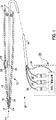
図1は本発明の塗布装置の一つの実施形態の側面図であり、同塗布装置が部分的に断面で示されている。
図2は本発明のスプレー先端部及びノズルの終端部の側面図である。
図3は、噴射ガスを伴わない液体混和及び液体の流れを示す、本発明のスプレー先端部又はノズルの終端部の側面図である。
図4は噴射ガスが組み込まれていることを除いて図3と類似の図である。
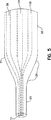
図5は本発明のスプレー先端部の側面図である。
図6A及び図6Bは本発明の先端部形成方法の図である。
図7〜図9は本発明の様々な先端部/開口/内孔の形状を示している。
好適な実施形態の詳細な説明
本発明は、例えば外科用シーラントのような生体適合材料を形成する二つ又はそれ以上の液体の塗布を向上させることに寄与する。本装置及び本方法は、低空気流量及び低液体流量での均一な混和を提供し、これによって空費及びエーロゾルを減らすと共に薄くてむらのないシーラントの層を塗布する能力を提供する。この新規の装置及び方法に適している適用の例はフィブリンシーラントであり、この適用例においては、エドワードソンらの欧州特許第592242号に示されるように、フィブリノーゲン溶液及びトロンビン溶液、又は、フィブリンモノマー溶液及びph10緩衝液のようなフィブリン重合化溶液とすることができる二つ又はそれ以上の液体成分を混和して塗布するのを助けるために、空気のようなガスが使用される。例えば、液体は、フィブリノーゲン溶液と、フィブリノーゲンからのフィブリノペプチドA及びBの一方又は両方の裂開を引き起こすことができる酵素の溶液とである。本願で使用されるように、用語「全液体/流量」又は「液体流量」又は「シーラント流量」はフィブリノーゲン溶液及びトロンビン溶液又はフィブリンモノマー溶液及びフィブリン重合化溶液の合わせられた液体の流量を指している。これらの液体成分に加えて、他の有用な液体又は薬品が添加されて、上述の液体成分の一つ又は両方と共に又は個別の経路を介してのいずれかで、共に塗布されてもよい。例えば、欧州特許第592242号において記述されているような又は技術的に公知であるような、制ガン剤、抗生物質、及び調合薬といった薬剤を共に塗布することができる。さらに、使用される特定の生体適合材料において有用となるであろう各種の細胞を共に塗布することができる。その上、塗布される生体適合材料の基本的構造又は特性を変動又は制御させることができる、液体、ポリマー、又は他の薬品、例えば親水コロイド、アルギン酸エステル、及び補助的に使用される他の物質をも共に塗布することができる。
塗布装置は技術的に公知のもののいずれでもよく、例えば従来技術において外科用シーラントの送達に有用であるとして知られている二重バレルシリンジであってもよい。本発明はさらに国際公開公報WO97/20585号に記載されており図1にも示されるものと幾つかの点で類似している塗布装置へ組み込むのに適している。従って、図1は全体を参照番号10で示される塗布装置を示しており、同塗布装置はスプレー先端部又はノズル14を有する自由選択の柄12と塗布を開始させるための選択自由な作動装置16とを有するアプリケータ11を含む。スプレーノズル又は先端部14は概略平坦な縁表面14′で終端しており、同縁表面14′は先端部14の長手方向に対してほぼ垂直であって、(図示されていない)出口開口を含んでおり、塗布時にこの出口開口を通してガス及び液体が分配される。アプリケータ11は管手段18を介して塗布される液体及びガスの供給源20と流体連通している。
本方法は150:1から1500:1までの空気流量対液体流量の比で合流させられる1.25リットル/分以下の低流量を使用する。好適には、空気流量は1.0リットル/分以下であり、空気流量対液体流量の比は約200:1から約1200:1までとなる。最も好適な比は400:1と1150:1の間である。これは、全液体流量が極めて低いこと、すなわち約3.0ml/分以下、好適には1.9ml/分以下で、0.5ml/分以下のことさえあるが、最も好適には0.5〜1.5ml/分の範囲であることを規定している。好適なガス流量は約500ml/分から約800ml/分である。これらの低空気流量及び低液体流量はシーラント塗布の優れた効率と制御とを提供するが、シーラント法が典型的には、手術において使用されるシーラントの量を固定して、すなわち、限定して行われることを考えると、このことが重要となる。好適には、例1の表1に示されるように、より高いガス流量にはより高い比が使用され、逆もまた同じである。シーラント成分のより効率的な利用に加えて、複数の薄い層のシーラントは、部分的にしか反応せずに最終的にシーラントを形成するであろう、厚くて、効率の劣る、不十分な混合状態のシーラント成分の集まりよりも効率が高いと思われる。
例えばシーラントのような生体適合材料を形成する液体成分の適切な混和及び塗布は、かなり小さな寸法であって互いのごく近傍にある液体開口及びガス開口を有するスプレーノズル又は先端部を有するアプリケータにおいて最も旨く達成されることがさらに分かっている。結果的に、それぞれが300μm以下の内径を有する少なくとも三つの開口を有するスプレー先端部が開発された。ここで、三つの開口において、二つの開口はシーラントを形成する液体成分のためのものであり、第三の開口はスプレーガスを供給する。このようなスプレー先端部14の側面図が図2に示されている。付加的な開口が第二ガス、付加物、又は内視鏡的な使用のための案内ワイヤのために設けられてもよい。好適には、液体成分のための開口は250μm以下の内径を有し、より好適には25μmと150μmの間の内径を有し、最も好適には約50μmと120μmの間の内径を有する。ガス開口は液体開口と同じ内径を有することができ、あるいは、好適には、本方法に使用されるときの液体開口よりも直径で20%から50%大きくなる。したがって、図2に示される一つの好適な実施形態においては、アプリケータのスプレー先端部表面14′は、直径で100μmの二つの液体開口13、15と、直径で約140〜150μmのガス開口17とを有する。好適には、開口は直線上にあって、ガス開口は国際公開公報WO97/20585号に示される通りその直線の一方の端部にくる。塗布される液体が1:1以外の比で供給されるのであれば、最も少ない量の液体がガス開口から最も遠くの開口から出るようにさせることが好ましい。好適な実施形態においては、フィブリンモノマー溶液(ph4)と緩衝溶液(ph10)とが欧州特許第592242号公報の方法で開示される通り7:1の比で塗布される。このような場合には、ph10の溶液が三つの直線上の開口の一方の端部にある第一開口、すなわち図2の開口13から出るようにさせ、フィブリンモノマー溶液が中央開口、すなわち開口15から出るようにさせることが望ましいことが分かっている。上記の構成は、本発明の装置及び方法を使用するときには、液体成分の混和能力を大いに高めることが分かっている。
本発明による液体成分の混和は、開口の大きさ、低液体流量、使用される生体適合材料形成液体の表面張力の特性、及び各開口間の間隔に関連している。したがって、全くガスを使用しない場合、約3.0ml/分以下の液体流量、好適には本願に記載された低液体流量の低い方の端の液体流量、例えば0.5ml/分〜0.7ml/分の液体流量においては、フィブリンシーラント形成液体は、概略的には、液滴が液体流の力によりスプレー先端部から離れる前に表面張力によりそれぞれがスプレー先端部14の表面14′で液滴を形成することが分かっている。その液滴は開口の直径よりも大きいものである。このことは低倍率で容易に観察することができ、表面でのこのおよその「液滴直径」が各種の液体に関して観察され得る。これらの液滴が所望の目標に向かってスプレー先端部から強制的に出される前に互いと部分的に重なる又は接触するように各液体開口の間の間隔がなっているときに、優れた混和が得られることが分かっている。図3は、空気を伴わず、低流量の二つの液体を使用しているスプレー先端部14を示している。二つの液体は、(その時に混和された)液体が目標に向かってスプレー先端部14から強制的に出される前に先端部表面で、結合された液滴19を形成する。この点に関して、フィブリンシーラント形成液体の場合には、各液体開口間の間隔は好適には一方の開口の直径の70%と120%の間であり、より好適には一方の開口の80%と90%の間であることが分かっている。すなわち、100μm液体開口を有するスプレー装置の場合には、それらの開口間の端部間距離は70μmと120μmの間であるべきであり、好適にはその間隔は80μmと100μmの間であるべきである。別の方向を見ると、本発明の好適な混和方法によれば、直径100μmの複数の液体開口を有するスプレー先端部は、理想的には、170μmと220μmの間の中心間距離でそれらの開口を有し、最適には180μmと200μmとの間の中心間距離でそれらの開口を有する。隣接する液体開口から離間されているガス開口は、好適には、上述された間隔と同じ範囲にあるが、使用されている液体開口間の間隔と全く同じでもよく、又はそれと異なってもよい。
スプレー塗布時、すなわち、本発明の空気流量対液体流量の前述の比での本発明の前述の流速において空気又はガスが使用されるとき、スプレー先端部の表面において混和する液滴は、それの液滴が空気流へ吸い込れてより小さな大きさの液滴に粉砕され所望の場所への供給時にさらに混和される前の、液体成分の予備混和として機能する。これが図4に示されており、図4においては、結合された液滴19が空気流へ吸い込れるのが見てとれる。基本的には、スプレー先端部又はノズルから塗布されるスプレー液滴は、所望の場所に接近すると円錐形状となる。本発明の装置及び方法のテーパ角度は選択された流量及びスプレー距離に従って適度に調節可能である。スプレーは約10°から約40°までの達成可能な角度範囲に進み、したがって、アプリケータが目標領域を横切って帯状に横方向に移動させられると、適度に再現可能である幅のシーラントが塗布される。
上述されるように、スプレー先端部又はノズルの開口の理想的な間隔はガス流なしで決定される。このことはさらに、本発明の一部分である新規のピンポイントシーラント塗布方法に道を与える。このことは図3を再度参照することによって分かる。上述されたように、各液体がスプレー先端部14の表面14′で結合された液滴19を形成して部分的に重なっている表面張力液滴を形成するように、二つの液体開口が離間されている。低液体流量、すなわち好適には1.0ml以下の流量においては、これらの結合された液滴が一度に一つか二つスプレー先端部から押し出されて、非常に均一に混和されて正確な位置に制御され、本質的には液滴式である外科用シーラントの塗布を提供する。例えばある特定の神経を使う修復手法といった、一点集中のアプリケータが必要とされ且つ広い領域を覆うことは必要とされない特定の場合には、この塗布が好ましいとされる。
本装置の開口が非常に小さいことから、各液体の小領域のみが互いに対して及び外部の環境に対して晒されることになる。したがって、本スプレー先端部が目詰まりする傾向は大きく低減させられる。さらに、本発明のスプレーアプリケータは、国際公開公報WO97/20585号に説明されているように、スプレーモード又は供給モードを中断するときに、各液体が実際に開口へ短い距離だけ引き戻されるようにされてもよい。各液体がピストン駆動されるシリンダから管手段を介してスプレー先端部へ供給されるとき、これはピストンを僅かに引き戻すことによってなされ得る。しかしながら、もし二つのシーラント形成液体が本発明によるスプレーアプリケータの先端部表面に残ると、そうして形成された結合された液滴は(重合を始めるかもしれないし始めないかもしれないが)、部分的にガス開口と重なっていて、又は、ガス開口の十分近くにあって、ガス流のみの継続又は開始が目詰まりさせる可能性のある物質を容易に除去することが分かっている。この先端部清浄化目的としてのみで使用されるガス流量は、本発明で使用される空気流量の範囲内又はそれを越える任意の好都合な流量とすることができる。好適には、この先端部清浄流量は液体スプレー供給に対して使用されるガス流量と同じ又は1.5〜2.5倍である。液体及びガスのアプリケータへの供給が例えば国際公開公報WO97/20585号に開示されているようにマイクロプロセッサによって制御されている装置においては、空気流量を手順の中にプログラムすることが有効であることが分かっており、この手順においては、液体成分の塗布の後に、一定の周期時間の間、例えば約30秒まで空気流が継続される。この「空気のみ」の清浄化ステップがさらに塗布サイクルの頭にプログラムされることができる。
当業者であれば分かるように、本発明によって規定された寸法のスプレー先端部又はノズルを形成することは高精度の作業である。スプレー先端部のように射出成形が可能である一方で、必要とされる寸法を考慮することは困難を伴う。本発明によれば、熱可塑性多内孔管を制御して加熱及び伸張することによって、スプレー先端部が形成されることができる。ここで、実際には、このような加熱/伸張の前の管の寸法は所望の先端部寸法の数倍の大きさである。例えば、低密度ポリエチレン管は、例えばプトナム社(Putnam Co.)から、同じ内径又は様々な内径の幾つかの内孔を有する多内孔管として商業的に入手可能である。意外なことであるが、これらのような非常に小さい直径の管は、全体の寸法を縮小することを除けば、内孔を閉鎖したり管の基本的な形状を破壊したりせずに、さらに引っ張られて縮小されることができる。図5は多内孔管21から形成された本発明のスプレー先端部14を示している。多内孔管21は遷移部分25と一体的になっている縮小された管23のまさしく端部にスプレー先端部14を有する。遷移部分25においては、外側の管と内部の内孔27、29、31の寸法とが縮小された管23の寸法から主要部管33の寸法へと遷移する。0.35mmの内孔を有する多内孔管は、寸法を縮小させるために、例えば100μmの内孔を提供するためには3.5倍まで、50μmの内孔を提供するためには7倍まで、25μmの内孔を提供するためには14倍にまで、注意深く加熱されて引っ張られることが分かっている。この注目すべき発見は、精度の良いスプレー先端部を作成する極めて費用効率のよい方法を提供するが、この精度の良いスプレー先端部を従来の熱可塑性材料の射出成形を使用して(任意の費用で)作成するのは事実上は不可能である。さらに、これらの寸法においては、早すぎるクロット生成又は目詰まりの問題なく、血液成分が容易に供給可能であることが驚くべきことに分かっている。
上述されており、図6A及び図6Bを参照して以下でより詳細に説明される方法が好ましいとされる一方で、これらのスプレー先端部を作製するのに適した任意の方法又は技術を使用することができる。スプレー先端部は上述されたような熱可塑性材料からなってもよければ、金属又はセラミック材料からなってもよい。選択された材料及び寸法によって、成形、レーザ穿孔放電加工(EDM)法又はスパーク浸食法のような公知の技術を本発明のスプレー先端部を作製するために使用することができる。
本発明の一部分である管及び先端部の構成の別な実施形態が図7〜図9に示されている。図7は、直線に並んだ複数の開口、すなわちガス開口17と液体開口13及び15を有する表面14′を有するスプレー先端部14を示している。付加的な液体又はガス用、付加的な試薬又は補形剤用、又は内視鏡的な目的の案内ワイヤ用として使用されることができる予備開口50がさらに示されている。さらに、予備開口50は管自体に所望の安定性又は可撓性を与えるためだけに存在することもある。三日月形開口52は、第二ガス開口、すなわち、ガス開口17に追加されたものであり、この三日月形開口52は以下で説明される先端部清浄方法において有効であることが分かっている。
図8Aは、一体となっているが分離することも可能な内孔30を有する管断面を示しており、この内孔30は図1に示されるように作動装置/圧力センサ管30として使用されることができる。図8Bは、分離可能な内孔30が主要部内孔からどのようにして分離されることができるかを示している側面図である。
図9は、三つの直線上に並んだ開口13と分離可能な内孔30と予備内孔54、56とを有する表面14′を有する先端部14を示しており、予備内孔54、56は、特別なガス、特別な液体、試薬又は補形剤、又は内視鏡案内ワイヤのため、又は単に管の安定性/可撓性を変更するために使用されることができるものである。
図6A及び図6Bは本発明の新規のスプレー先端部を形成するための方法をさらに示している。管18の一部分が、固定されたクランプ40とスライド可能なクランプ42との間に保持される。本願で説明される原理が任意の熱可塑性管と共に用いられることができるが、選択された管材料とその熱可塑性の特性とに関するある種の基本的な知識を必要とする。例として、プトナム社の低密度ポリエチレン4内孔管は、約2.5mmの外径を有し、350μmと500μmとの間の内径を有する四つの内孔を有する。図6Aから分かるように、熱源が両クランプ間の領域に加えられる。5〜10cmの長さ部分へ熱を加えることが有効であることが分かっているが、これは所望の形状にしたがって変動する。管18が非破壊的変形を始めて引っ張られることができるようになるまで、熱が加えられる。本願で述べられた典型的な管に対しては、約280℃が十分な熱源である。管が液体又は柔軟になると、スライド可能なクランプ42が予め設定された距離動かされる。例えば、もし図6Aの距離xが10cmであれば、図6Bに示されるように距離が3.5x又は35cmとなるように、クランプ42が引っ張られることができる。こうすることで寸法を約3.5倍まで縮小させることが分かっている。結果的に、縮小された管23の中心においては、図6Aの内孔内径がそれぞれ約350μm及び500μmから約100μm及び150μmまで縮小された。図6Bに示されるように、管18を切断して所望のスプレー先端部を形成するために、カッタ44が使用されることができる。さらに、図5を再度参照すると、先端部14に対して所望される開口の大きさにしたがって、縮小された管23又は遷移部分25の任意の場所において、先端部14を形成することができることが分かるであろう。主要部管33の内孔の直径と先端部14の内孔の直径との間の関係が所望されるスプレーの質に寄与することがさらに進行中の研究から明らかであり、先端部及び管が単一部品材料からなる場合には3:1から14:1の比が有効であることが分かっている。縮小された管23又は遷移位置25のいずれかに沿った所望の位置に先端部14を形成するための切断は、開口の直径のみならず主要部管33の内孔直径に対する開口直径の比を確立する役割をする。
図5及び図6Aを参照すると、(図示されていない)測定手段がさらに本願において説明された先端部形成方法において使用されることができる。このような測定手段は、光学的又は機械的方法のいずれかで内孔の内径又は管の外径を測定することによって、所望の大きさ又はスプレー先端部の所望の特性のいずれかを決定する目的を有している。こうして、先端部を形成するための切断が縮小された管23又は遷移部分25のいずれかに沿った精度の良い正確な位置で行われることが可能となる。代替的には、ガス又は液体が切断段階時に管18の中を流されて、所望の流れが感知されるまで測定手段が縮小された管23及び/又は遷移部分25を上流へ主要部管33に向かってカッタを動かし続けることができるようにする。
本発明による好適なスプレーアプリケータは、一体型の一つ部品の管とスプレー先端部を備える。すなわち、一方の端部において、多内孔管が上述のされたように縮小されたスプレー先端部を作るように変更され、多内孔管の本体は液体成分源からスプレー先端部まで流体連通させる管手段として機能する。再度図1を参照すると、本質的には、図5に示されるような多内孔管は管手段18として機能し、管手段18の第一端部は液体源22、24及びガス源26へ接続する。管の第二端部においては、管は、スプレー先端部又はノズル14へ接続されるというよりも、本願に記載されるようにスプレー先端部又はノズル14の中に接続されるように形成される。好適には作動装置16を有する選択自由な柄12は、管18に沿った任意の場所、例えば外科医による最大限の方向調節のためにノズル14の端部の近くに、又は、管18の長さ部分及びスプレー先端部14が例えば内視鏡目的のために有効となるよう柄12から外へ延びるように管18に沿ってさらに後方に、配置されることができる。
図1に示される作動装置16は国際公開公報WO/9720585号の開示内容の一部である。本質的には、感知用空気管又はガス管30に接続されている圧力スイッチ28が、例えばエラストマー材料の可撓性膜であってもよい作動装置16の下にある。感知用空気管又はガス管30の反対側の端部がガス源及び空気源20の制御/駆動装置に接続された状態でさらに示されている。作動装置16を押すと、圧力差が感知用空気管又はガス管30に生じ、この圧力差が制御/駆動装置において信号として検出される。この信号に応じて、液体源22及び24とガス源26の内容物が管手段18を通るそれぞれの内孔32、34、及び36で送られ、スプレー先端部14の(図1には示されていない)開口13、15、17から外へ出される。感知用管30は管手段18とは別個のものとされてもよく、図1に示されるように管手段18と一体であるが分離可能なものとされてもよい。図1の塗布装置10はさらに保持スリーブ32を含んでもよく、この保持スリーブ32は、熱可塑性材料又はエラストマー材料から作ることができ、縮小された管23と柄12のノズル端部34との間のすべりばめを提供する。さらに、グロメット36が柄12の後部分に含まれていてもよい。本発明の塗布装置10のアプリケータ11の取扱い及び使用の間、管18及び先端部14に安定性を与えるために、スリーブ32及びグロメット36が追加される。柄12は任意の半剛性材料又は剛性材料から作られることができ、医療装置分野で使用される塑性材料が、軽くて製造しやすいという点で、有効である。
国際公開公報WO97/20585号はさらに、本願の図1に示されるように、供給源、すなわち国際公開公報WO97/20585号で参照されているような放出手段は、液体成分源又はガス成分源が外科医の手に保持されないように、前記スプレーノズル又は先端部から好適には離れた位置に設けられる。このことにより、管手段/スプレー先端部は、柄があるかないかにかかわらず、このような塗布装置においてアプリケータとして機能するようになる。このように、従来技術と比較してずっと整然として取扱いやすいアプリケータが提供されることが分かる。本願の供給源又は放出手段はさらにマイクロプロセッサ制御が可能である。これらの特徴全ては本発明の好適な実施形態の一部である。本発明の一部である様々な流量及び比が供給源の制御/駆動装置にプログラムされることができ、外科医は特定の手法及びその時の外科的必要性に従って流量及び比を選択し、さらには変更することさえできるようになる。所望のスプレー/塗布特性を提供するためにガス又は空気が脈動させられ得ることが本発明の一部としてさらに企図されている。さらに、本発明によれば、作動装置を押すことによって以下のようにすることができる。
1)作動装置が次に押されるまで、液体及びガスの供給が「オン」になる。
2)作動装置が押されている間は液体及びガスの供給が「オン」になり、作動装置が放されると「オフ」になる。
3)作動装置が押される毎に計量された量の液体及びガスが分配される。
本発明は次の例によってさらに説明されるが、そこで説明される詳細に限定されるべきではない。
例1
混合
この例は、本発明の方法及び装置を使用した、フィブリンシーラントを形成するために塗布される二つの液体成分の混合を評価することを目的とされている。欧州特許第EP592242号においてエドワードソンらによって開示されているフィブリンシーラントの混合効率は、二つの液体が、pH4のフィブリンモノマー溶液と、混合された溶液を中性にして、フィブリンモノマーのフィブリンポリマー、すなわちフィブリンシーラントへの重合に寄与するpH10の緩衝液とであることから、容易に評価されることができる。したがって、これらの液体をpH紙にスプレーすることによって、混合を観察することができる。
本質的には図1、図4、及び図5に示されるようなスプレーアプリケータは、100μm直径の二つの液体開口と150μm直径のガス開口とを有するスプレー先端部を有する。各開口は直線上に配置されており、一方の端部にガス開口、中央にフィブリンモノマー溶液開口、直線上の各開口の他方の端部にpH10の緩衝溶液開口がある。開口は(端部間で)およそ90μm離れていた。
欧州特許第EP592242号においてエドワードソンらによって記載されているようにフィブリンモノマー溶液が準備され、pHは4であった。同様に欧州特許第EP592242号において記載されるように、これがpH10の炭酸塩/重炭酸塩緩衝溶液と共に、フィブリンモノマー溶液と緩衝溶液の比7:1で共に塗布された。
これらの液体が、以下の表1のパラメータに従って、ワットマン社(Whatman)から入手可能である全範囲(1〜14)pH紙の20cm2面積部分に塗布された。これらのスプレーパラメータが以下の例2においても使用された。

試験されたアプリケータはいずれも不完全混合を示さず、クロットは常にpH紙の緑色によって示される中性pHであった。この観察は、クロットがよく混合されていたことを示している。扱われた全てのサンプルはよく混合されており、最も密集したものは全てpH7であった。
例2
ここで記載された以外のものは、上の例1及び表1で示された同じ装置、液体、及びスプレーパラメータがこの実験で用いられた。この実験で使用されたフィブリンモノマー溶液は、フィブリンクロットの観察をより容易にさせるためにローダミンの1%水性液20μlを加えられる。
アプリケータが特別製作の用具内に水平に保持されて、20cm2のガラス板から5cm又は10cmの距離に直角になっている。塗布先端部とガラス板との間の直線上の点がガラス板上に描かれた。この点は塗布目標とされるべきものであった。
5秒間の間、スプレーが目標の前に配置された遮蔽物に塗布された。次に、遮蔽物が除去され、途切れることなく、さらに10秒間、ガラス板へのスプレーが続けられる。生成したクロットの直径と、さらに目標からクロットの距離とに注意が払われた。あらゆる漏れ、封鎖、又はスプレー性能の明らかな低下に注意が払われた。
この例2の目的は、例1に記載されたようなアプリケータによって生成された、スプレー直径、スプレー方向、及び円錐角を評価することである。ここに記載される実験を通して10個のアプリケータが使用され、結果が表2に編集されている。
The present invention relates to a method of applying a mixture of at least two liquid components forming a biocompatible material to a desired site, and more particularly to applying at least two components to form a surgical sealant, such as a fibrin sealant.
Background art
Many biocompatible materials, such as biopolymers (biopolymers), are used in the medical community. Many of these biocompatible materials are formed from two or more liquid components, and thus can be formed in situ by applying such components together. An example of this is a surgical sealant, such as a fibrin sealant, which can be formed by applying a fibrinogen component and a thrombin component together.
Redl, U.S. Pat. No. 4,359,049, discloses a double barrel syringe that is useful for applying a tissue adhesive such as fibrin glue or fibrin sealant to a human or animal in need thereof. . The described fibrin sealant mainly comprises two main components, each in liquid form when used: a fibrinogen-containing component and a thrombin-containing component. Basically, when thrombin and fibrinogen are mixed, the peptide chain of fibrinogen is cleaved and the resulting fibrin becomes a clot that is useful for sealing fluid and air leaks to join hemostasis and tissue. And conditions for polymerization. To avoid premature clot formation, a double barrel applicator is used, which, of course, keeps the two components in isolation until application to the patient is required. U.S. Pat. No. 4,359,049 discloses that pistons in two cartridges, each containing one component, can be commonly actuated to dispense fluid from each simultaneously.
Other prior art patents describe various blending methods for blending two or more components used in these surgical sealants and other surgical sealants. For example, U.S. Pat. No. 5,116,315, assigned to Hemaldics, describes a mixing head in which a liquid conduit leading from a component cartridge enters the mixing chamber, where each component is in a mixed chamber. It is formed so as to impart a spiral motion of each component before coming out through the common outlet flow path. For proper mixing of the components, it is desirable to form a uniform fibrin sealant. Inefficient mixing results in administration of fibrinogen and thrombin together, which will actually produce only a small yield of sealant. The trouble with the fibrin sealant applicator is the formation of premature clots in the device, in particular the device in which each component is mixed in the mixing head and / or the device in which each component exits through a common flow path. It is done. After the initial spray of sealant, the clot can block the outlet flow path, making the applicator useless or greatly reducing the surgeon's flexibility in performing the sealant application portion of the surgical procedure.
Immuno U.S. Pat. No. 4,631,055 includes a gas delivery channel for blowing gas into a needle or blending head during the release of each component. However, a uniform and uniform distribution of material to the anatomical region of interest has not yet been achieved. In fact, a considerable amount of each component is wasted.
U.S. Pat. No. 5,605,541 discloses an apparatus and method for applying the components of a fibrin sealant. The apparatus comprises a gas source and a reservoir for each component, and the gas source and each of the components are discharged through independent openings. Preferably, gas is released from the central opening and each component is released separately from each fibrin sealant forming component through each of the annularly arranged openings.
Edwardson et al. European Patent No. 592242 discloses the first fully self-derived fibrin sealant. This patent provides co-administration, which is the simultaneous administration of a fibrin monomer solution and a buffer solution that contributes to the polymerization of the fibrin monomer, where the fibrin monomer is a single blood source (preferably for patients receiving a sealant). It can be made within 30 minutes from the blood source). This breakthrough technique delivers a fixed amount of fibrin monomer solution from approximately 140-160 ml of blood sample. To benefit from this safe and efficient autologous sealant product, uniform and efficient blending is even more important, so to apply two or more components that form a surgical sealant New devices and methods are required.
The ideal application of fibrin sealant requires efficient utilization of each sealant component in order to maximize coverage and effective usage. Efficient utilization is achieved, among other things, by thorough mixing of each component, controlled and uniform application of each component, the ability to apply each component intermittently, and minimizing the aerosol. It is further desirable that the surgeon can vary the application speed according to a particular method and operate in an area very close to the tissue to be sprayed, i.e. 10 cm or less, or even 5 cm or less.
Among the parameters, mixing and clogging can be the most disruptive to the performance of the sealant applicator. Inadequate mixing results in the application of the individual sealant components together, and only a fraction of the desired amount of sealant is actually formed. This wastes and leads to poor sealant performance. As each sealant component begins or continues the agglomeration cycle when blended with each other component, the above-mentioned hemaldic devices are limited and most current sealant applicators are designed to avoid clogging. It is designed to mix each component outside. Those skilled in the art will recognize that it is difficult to control proper mixing and application, assuming that significant mixing of each component occurs as each component exits the device rather than inside the device. Let's go. The properties of the applied sealant film are greatly influenced by the mixing / spraying parameters and the fluid dynamics of the two liquids as each liquid exits the apparatus tip or nozzle. Clogging is often the result of premature contact of each sealant component within the device, but in general, the handling and transfer of blood within plastic and / or glass tubes and instruments is essentially essential. This is a problem, especially if the internal dimensions of the device / tube are small.
US Pat. No. 5,582,596 to Fukunaga et al. Discloses a spray applicator suitable for fibrin sealant, which can be connected to a gas source. Two liquid nozzles are provided concentrically within the two larger nozzles. US Pat. No. 5,582,596 describes that the liquid nozzle protrudes from the gas nozzle by about 100 μm to 10 mm. U.S. Pat. No. 5,582,596 further describes that each liquid nozzle is separated from about 1.0 to about 20 mm. A commercially available applicator for Bolheal® sealant, which appears to be an embodiment of US Pat. No. 5,582,596, actually protrudes about 600 μm from the gas spout and is about 625 μm. There are two liquid nozzles having an inner diameter, each liquid nozzle being 3.0 mm between the centers or about 2.4 mm apart. Product and US Pat. No. 5,582,596, for example, 0.75 kg / cm 2 ~ 4.0kg / cm 2 This suggests that low pressures can be used, but no mention is made of air flow or sealant flow. There remains room for improvement in spray angle, aerosol, and working distance suitable for this device.
International Publication No. WO 97/20585 describes a new spray applicator for fibrin sealants that utilizes "straight line" openings at the spray tip for releasing air (or other gases) and each sealant component. Disclosure. The device uses a relatively low air flow rate, i.e. 1.25 liters / minute, and the sealant flow rate is about 2.0 ml to about 5.0 ml. Each opening in the spray tip is only about 300 μm in inner diameter and about 200 μm apart, ie, about 500 μm in the center-to-center distance. The device is believed to be one of the smallest nozzle sizes for blood or fibrin sealant application. Although the aerosol is greatly reduced and the spray angle and blending are improved, a more precisely controlled spray, with less aerosol and more efficient use of each sealant component, is an effective addition to the prior art. It will be.
Disclosure of the invention
In accordance with the present invention, improved mixing and application of the two liquid components that form the biocompatible material with minimal aerosol results in a ratio of air flow to total liquid flow from about 150: 1 to about 1500: 1. And using an air flow rate of about 1.25 liters / minute or less. Preferably, the air flow rate is about 1 liter / min or less and the ratio of air flow to total liquid flow is from about 200: 1 to about 1200: 1. Ideally, the parameters are tailored to be suitable for spray application of each component that forms a surgical sealant, eg, a fibrin sealant. Further, some of the present invention provides a novel method for applying a biocompatible material such as a surgical sealant at a liquid flow rate of 1.9 ml / min, a novel spray tip, a biocompatible material applicator and A method for making such an applicator, the novel application method comprising mixing such ingredients at the spray tip or nozzle exit surface.
[Brief description of the drawings]
FIG. 1 is a side view of one embodiment of the coating apparatus of the present invention, the coating apparatus being partially shown in cross section.
FIG. 2 is a side view of the spray tip and nozzle end of the present invention.
FIG. 3 is a side view of the spray tip or nozzle end of the present invention showing liquid mixing and liquid flow without propellant gas.
FIG. 4 is a view similar to FIG. 3 except that the injection gas is incorporated.
FIG. 5 is a side view of the spray tip of the present invention.
6A and 6B are diagrams of the tip portion forming method of the present invention.
7-9 show various tip / opening / inner hole shapes of the present invention.
Detailed Description of the Preferred Embodiment
The present invention contributes to improving the application of two or more liquids to form a biocompatible material such as a surgical sealant. The apparatus and method provide uniform blending at low air and liquid flow rates, thereby reducing the expense and aerosol and providing the ability to apply a thin and even layer of sealant. An example of an application suitable for this new apparatus and method is a fibrin sealant, in which fibrinogen and thrombin solutions or fibrin monomers as shown in Edwardsson et al. A gas, such as air, is used to help mix and apply two or more liquid components, which can be a solution and a fibrin polymerization solution such as ph10 buffer. For example, the liquid is a fibrinogen solution and a solution of an enzyme that can cause cleavage of one or both of fibrinopeptides A and B from fibrinogen. As used herein, the term “total liquid / flow rate” or “liquid flow rate” or “sealant flow rate” refers to the combined liquid flow rate of fibrinogen solution and thrombin solution or fibrin monomer solution and fibrin polymerization solution. Yes. In addition to these liquid components, other useful liquids or chemicals may be added and applied together, either with one or both of the liquid components described above, or via separate routes. For example, agents such as anti-cancer agents, antibiotics, and pharmaceuticals can be applied together as described in European Patent No. 5,922,242 or as is known in the art. In addition, various cells that may be useful in the particular biocompatible material used can be applied together. In addition, liquids, polymers, or other drugs, such as hydrocolloids, alginates, and other substances used auxiliary, that can vary or control the basic structure or properties of the applied biocompatible material Can also be applied together.
The applicator device can be any known in the art, for example, a double barrel syringe known in the prior art to be useful for the delivery of surgical sealants. The present invention is further suitable for incorporation into a coating apparatus described in WO 97/20585 and similar in some respects to that shown in FIG. Accordingly, FIG. 1 shows an applicator device generally designated by the
The method uses a low flow rate of 1.25 liters / minute or less that is merged at a ratio of air flow to liquid flow from 150: 1 to 1500: 1. Preferably, the air flow rate is 1.0 liter / min or less and the ratio of air flow to liquid flow is from about 200: 1 to about 1200: 1. The most preferred ratio is between 400: 1 and 1150: 1. This is because the total liquid flow rate is very low, i.e. about 3.0 ml / min or less, preferably 1.9 ml / min or less and even 0.5 ml / min or less, most preferably 0.5 ml / min or less. It is specified to be in the range of ˜1.5 ml / min. A suitable gas flow rate is from about 500 ml / min to about 800 ml / min. Although these low air and liquid flow rates provide excellent efficiency and control of sealant application, sealant methods typically fix the amount of sealant used in surgery, i.e., limited. This is important considering what is done. Preferably, as shown in Table 1 of Example 1, higher ratios are used for higher gas flow rates and vice versa. In addition to more efficient use of sealant components, multiple thin layer sealants are thick, less efficient, and poorly mixed that will only partially react and eventually form a sealant It appears to be more efficient than a collection of state sealant components.
Appropriate blending and application of liquid components to form biocompatible materials such as sealants, for example, in applicators with spray nozzles or tips with liquid and gas openings that are fairly small in size and in close proximity to each other It is further known that it is best achieved. As a result, spray tips with at least three openings each having an inner diameter of 300 μm or less have been developed. Here, of the three openings, the two openings are for the liquid component forming the sealant, and the third opening supplies the spray gas. A side view of such a
The mixing of the liquid components according to the present invention is related to the size of the openings, the low liquid flow rate, the surface tension characteristics of the biomaterial forming liquid used, and the spacing between the openings. Thus, if no gas is used, the liquid flow rate is about 3.0 ml / min or less, preferably the lower end liquid flow rate of the low liquid flow described herein, eg 0.5 ml / min to 0.7 ml. At a liquid flow rate per minute, the fibrin sealant forming liquid generally drops on the surface 14 'of the
When spraying, i.e., when air or gas is used at the aforementioned flow rate of the present invention at the aforementioned ratio of air flow to liquid flow of the present invention, the miscible droplets on the surface of the spray tip It serves as a premixing of the liquid component before the droplets are drawn into the air stream and crushed into smaller sized droplets and further mixed when delivered to the desired location. This is illustrated in FIG. 4, where it can be seen that the combined
As mentioned above, the ideal spacing of the spray tip or nozzle opening is determined without gas flow. This further provides a way for the novel pinpoint sealant application method that is part of the present invention. This can be seen by referring again to FIG. As described above, the two liquid openings are spaced so that each liquid forms a
Since the opening of the device is very small, only a small area of each liquid will be exposed to each other and to the outside environment. Therefore, the tendency of the spray tip to be clogged is greatly reduced. Furthermore, the spray applicator of the present invention allows each liquid to actually be pulled back into the opening a short distance when interrupting the spray mode or supply mode, as described in WO 97/20585. May be. This can be done by slightly pulling back the piston as each liquid is supplied from the piston driven cylinder through the tube means to the spray tip. However, if two sealant forming liquids remain on the tip surface of the spray applicator according to the present invention, the combined droplets thus formed (although it may or may not begin to polymerize) It has been found that substances that partially overlap the gas openings or are sufficiently close to the gas openings to easily remove substances that can clog the continuation or initiation of the gas flow alone. The gas flow rate used solely for this tip cleaning purpose can be any convenient flow rate within or beyond the range of air flow used in the present invention. Preferably, the tip clean flow rate is the same or 1.5 to 2.5 times the gas flow rate used for liquid spray supply. In devices where the supply of liquid and gas to the applicator is controlled by a microprocessor, as disclosed for example in WO 97/20585, it is useful to program the air flow into the procedure. It has been found that in this procedure, air flow is continued for a certain period of time, for example about 30 seconds, after application of the liquid component. This “air only” cleaning step can be further programmed at the beginning of the application cycle.
As will be appreciated by those skilled in the art, forming a spray tip or nozzle of the dimensions defined by the present invention is a highly accurate operation. While injection molding is possible like a spray tip, it is difficult to consider the required dimensions. According to the present invention, the spray tip can be formed by controlling and heating and stretching the thermoplastic multi-bore tube. Here, in practice, the dimensions of the tube before such heating / elongation are several times the desired tip dimensions. For example, low density polyethylene tubing is commercially available as a multi-bore tubing having several bores of the same inner diameter or various inner diameters, for example from Putnam Co. Surprisingly, very small diameter tubes such as these, except for reducing the overall dimensions, without closing the bore or destroying the basic shape of the tube, It can be further reduced by pulling. FIG. 5 shows the
While the methods described above and described in more detail below with reference to FIGS. 6A and 6B are preferred, use any method or technique suitable for making these spray tips. can do. The spray tip may be made of a thermoplastic material as described above, or may be made of a metal or ceramic material. Depending on the materials and dimensions selected, known techniques such as molding, laser drilling electrical discharge machining (EDM) or spark erosion can be used to make the spray tip of the present invention.
Another embodiment of the tube and tip configuration that is part of the present invention is shown in FIGS. FIG. 7 shows a
FIG. 8A shows a tube cross-section with an
FIG. 9 shows the
6A and 6B further illustrate the method for forming the novel spray tip of the present invention. A portion of the
Referring to FIGS. 5 and 6A, measurement means (not shown) can be used in the tip formation method described further herein. Such measuring means determine either the desired size or the desired properties of the spray tip by measuring the inner diameter of the bore or the outer diameter of the tube in either an optical or mechanical manner. Has a purpose. Thus, the cut to form the tip can be made at a precise and precise location along either the reduced
A preferred spray applicator according to the present invention comprises an integral one-piece tube and spray tip. That is, at one end, the multi-bore tube is modified to create a reduced spray tip as described above, and the body of the multi-bore tube is in fluid communication from the liquid component source to the spray tip. Functions as a tube means. Referring again to FIG. 1, in essence, a multi-bore tube as shown in FIG. 5 functions as the tube means 18 with the first end of the tube means 18 leading to the
The
International Publication No. WO 97/20585 further includes a source of liquid, or a gas component source, as shown in FIG. 1 of the present application, ie the release means as referenced in International Publication No. WO 97/20585. In order not to be held by the surgeon's hand, it is preferably provided at a position away from the spray nozzle or tip. This allows the tube means / spray tip to function as an applicator in such an applicator device with or without a handle. Thus, it can be seen that an applicator is provided that is much more orderly and easier to handle than the prior art. The source or discharge means of the present application can be further microprocessor controlled. All of these features are part of the preferred embodiment of the present invention. Various flow rates and ratios that are part of the present invention can be programmed into the source control / drive device so that the surgeon selects the flow rates and ratios according to the particular technique and current surgical needs, and You can even change it. It is further contemplated as part of this invention that gas or air can be pulsed to provide the desired spray / application characteristics. Furthermore, according to the present invention, the operation device can be pushed as follows.
1) The liquid and gas supply is “on” until the actuator is next pushed.
2) The supply of liquid and gas is “on” while the actuator is pushed, and “off” when the actuator is released.
3) A metered amount of liquid and gas is dispensed each time the actuator is pushed.
The invention is further illustrated by the following examples, but should not be limited to the details described therein.
Example 1
mixture
This example is intended to evaluate the mixing of two liquid components applied to form a fibrin sealant using the method and apparatus of the present invention. The mixing efficiency of the fibrin sealant disclosed by Edwardson et al. In European Patent No. EP592242 is that the two liquids are a fibrin monomer solution of pH 4 and a fibrin polymer of fibrin monomer, i.e. neutralizing the mixed solution. Since it is a
Essentially, the spray applicator as shown in FIGS. 1, 4 and 5 has a spray tip with two liquid openings of 100 μm diameter and a gas opening of 150 μm diameter. Each opening is arranged on a straight line, with a gas opening at one end, a fibrin monomer solution opening at the center, and a buffer solution opening at
A fibrin monomer solution was prepared and the pH was 4 as described by Edwardson et al. In European Patent No. EP592242. This was also applied together with a
These liquids are available from Whatman according to the parameters in Table 1 below, the full range (1-14) of
None of the applicators tested showed incomplete mixing and the clot was always at a neutral pH indicated by the green color of the pH paper. This observation indicates that the clot was well mixed. All treated samples were well mixed, the most dense being all pH 7.
Example 2
Other than those described herein, the same equipment, liquid, and spray parameters shown in Example 1 and Table 1 above were used in this experiment. The fibrin monomer solution used in this experiment can be added with 20 μl of a 1% aqueous solution of rhodamine to make it easier to observe the fibrin clot.
The applicator is held horizontally in a specially made tool, 20cm 2 Is perpendicular to the distance of 5 cm or 10 cm from the glass plate. A point on a straight line between the coating tip and the glass plate was drawn on the glass plate. This point should have been a coating target.
Spray was applied to the shield placed in front of the target for 5 seconds. The shield is then removed and spraying on the glass plate continues for another 10 seconds without interruption. Attention was paid to the diameter of the generated clot and the distance from the target to the clot. Attention was paid to any leaks, blockages, or apparent degradation of spray performance.
The purpose of this Example 2 is to evaluate the spray diameter, spray direction, and cone angle produced by an applicator as described in Example 1. Ten applicators were used throughout the experiments described here and the results are compiled in Table 2.
Claims (11)
前記各液体のための個別の容器を備える前記各液体の供給源と、
第一端部において前記容器へ接続されており、前記各液体のための個別の流路又は内孔を含む、管手段と、
前記管手段の流れ方向にほぼ垂直な表面を有し、前記表面が前記各液体のための個別の開口を含み、前記開口は前記管手段の第二端部において前記個別の流路と流体連通している、スプレーノズル先端部と、
前記各液体の総流量を制御するための手段と、
を備え、
前記各液体の総流量を制御するための手段が前記液体の総流量を3.0ml/分以下に維持するようにプログラムされており、前記供給源が、前記生体適合材料の塗布の際に前記供給源を手に保持することを使用者に要求しないように、前記スプレーノズル先端部から離れた位置にあり、前記各液体開口がほぼ同じ直径であり、前記各液体の塗布時に、前記各液体が前記開口を出て、液体流れを継続させることにより先端部から所望の部位へ向かって押し出される前に、その表面張力によって前記スプレーノズル先端部の前記表面と互いとを同時に接触させ、それによって塗布される液体の混合を向上させるように、前記スプレーノズル先端部の前記表面の前記各開口間の間隔が前記各開口の一つの直径の約70%から約120%の範囲になっている、アプリケータ装置。An applicator device for applying to a desired site two or more liquids that form a biocompatible material when mixed;
A source of each liquid comprising a separate container for each liquid;
Tube means connected to the container at a first end and including a separate flow path or bore for each of the liquids;
A surface substantially perpendicular to the flow direction of the tube means, the surface including a separate opening for each of the liquids, the opening being in fluid communication with the individual flow path at a second end of the tube means. It is, and spray over Roh nozzle tip,
Means for controlling the total flow rate of each liquid;
With
Means for controlling the total flow rate of each liquid is programmed to maintain the total flow rate of the liquid at 3.0 ml / min or less, and the source is adapted to apply the biocompatible material during application of the biocompatible material. In order not to require the user to hold the supply in hand, the liquid nozzles are located at a position away from the tip of the spray nozzle, the liquid openings have substantially the same diameter, and the liquids are applied when the liquids are applied. There exits the opening, before being pushed towards the front end portion to the desired site by continuing liquid flow, at the same time contacting the said surface with each other of said spray nozzle tip by surface tension thereof, whereby as enhance mixing of the liquid to be applied, it ranges from about 70% to about 120% of one diameter spacing of each opening between the respective openings of said surface of said spray nozzle tip And it is, applicator device.
Applications Claiming Priority (4)
| Application Number | Priority Date | Filing Date | Title |
|---|---|---|---|
| US3094296P | 1996-11-15 | 1996-11-15 | |
| US60/030,942 | 1996-11-15 | ||
| US08/970,291 US6454786B1 (en) | 1996-11-15 | 1997-11-14 | Devices and methods for applying a mixture of two or more liquid components to form a biomaterial |
| PCT/US1997/020653 WO1998020931A1 (en) | 1996-11-15 | 1997-11-14 | Devices and methods for applying a mixture of two or more liquid components to form a biomaterial |
Related Child Applications (1)
| Application Number | Title | Priority Date | Filing Date |
|---|---|---|---|
| JP2007134424A Division JP2007307385A (en) | 1996-11-15 | 2007-05-21 | Apparatus and method for applying mixture of two or more liquid components to form biocompatible material |
Publications (3)
| Publication Number | Publication Date |
|---|---|
| JP2001505787A JP2001505787A (en) | 2001-05-08 |
| JP2001505787A5 JP2001505787A5 (en) | 2005-07-14 |
| JP4116083B2 true JP4116083B2 (en) | 2008-07-09 |
Family
ID=26706614
Family Applications (2)
| Application Number | Title | Priority Date | Filing Date |
|---|---|---|---|
| JP52279398A Expired - Fee Related JP4116083B2 (en) | 1996-11-15 | 1997-11-14 | Apparatus and method for applying a mixture of two or more liquid components to form a biocompatible material |
| JP2007134424A Withdrawn JP2007307385A (en) | 1996-11-15 | 2007-05-21 | Apparatus and method for applying mixture of two or more liquid components to form biocompatible material |
Family Applications After (1)
| Application Number | Title | Priority Date | Filing Date |
|---|---|---|---|
| JP2007134424A Withdrawn JP2007307385A (en) | 1996-11-15 | 2007-05-21 | Apparatus and method for applying mixture of two or more liquid components to form biocompatible material |
Country Status (15)
| Country | Link |
|---|---|
| US (2) | US6454786B1 (en) |
| EP (1) | EP0951311B1 (en) |
| JP (2) | JP4116083B2 (en) |
| AT (1) | ATE357946T1 (en) |
| AU (1) | AU721371B2 (en) |
| BR (1) | BR9713070A (en) |
| CA (2) | CA2271738C (en) |
| DE (1) | DE69737531T2 (en) |
| DK (1) | DK0951311T3 (en) |
| ES (1) | ES2284186T3 (en) |
| IL (1) | IL129916A0 (en) |
| NO (1) | NO992342L (en) |
| NZ (1) | NZ335751A (en) |
| PT (1) | PT951311E (en) |
| WO (1) | WO1998020931A1 (en) |
Families Citing this family (48)
| Publication number | Priority date | Publication date | Assignee | Title |
|---|---|---|---|---|
| WO2000062828A1 (en) | 1996-04-30 | 2000-10-26 | Medtronic, Inc. | Autologous fibrin sealant and method for making the same |
| DE19781869T1 (en) * | 1996-04-30 | 2000-03-16 | Medtronic Inc | Process for the production of an autologous fibrin hemostatic agent |
| WO2000015117A1 (en) * | 1998-09-17 | 2000-03-23 | Focal, Inc. | Self-cleaning fluid delivery device for medical applications |
| US6921380B1 (en) * | 1998-10-01 | 2005-07-26 | Baxter International Inc. | Component mixing catheter |
| ATE318608T1 (en) * | 1998-12-02 | 2006-03-15 | Bristol Myers Squibb Co | SPRAY ADMINISTRATION OF CELLS |
| CA2373738A1 (en) | 1999-06-01 | 2000-12-07 | Bristol-Myers Squibb Company | Fibrin polymer structure |
| CA2316554C (en) * | 1999-08-25 | 2007-10-23 | Bristol-Myers Squibb Company | Applicator and electro-mechanical applicator drive system |
| US7544177B2 (en) | 2002-01-24 | 2009-06-09 | The Regents Of The University Of California | Aerosol device to deliver bioactive agent |
| US7217254B2 (en) * | 2002-09-20 | 2007-05-15 | Genzyme Corporation | Multi-pressure biocompatible agent delivery device and method |
| US7077339B2 (en) * | 2003-02-03 | 2006-07-18 | Biomet, Inc. | Spray applicator |
| US20040254528A1 (en) * | 2003-06-12 | 2004-12-16 | Adams Daniel O. | Catheter with removable wire lumen segment |
| US7490738B2 (en) * | 2004-10-01 | 2009-02-17 | Angiotech Pharmaceuticals (Us), Inc. | Mixing and dispensing fluid components of a multicomponent composition |
| KR101225359B1 (en) * | 2005-01-12 | 2013-01-22 | 박스터 헬쓰케어 에스.에이. | Hand triggered tissue sealant spray apparatus and system |
| US7611494B2 (en) * | 2005-02-08 | 2009-11-03 | Confluent Surgical, Inc. | Spray for fluent materials |
| EP1848488B1 (en) | 2005-02-18 | 2012-01-04 | Tyco Healthcare Group LP | Rapid exchange catheter |
| US7766900B2 (en) * | 2005-02-21 | 2010-08-03 | Biomet Manufacturing Corp. | Method and apparatus for application of a fluid |
| US8603138B2 (en) * | 2006-10-04 | 2013-12-10 | Ethicon Endo-Surgery, Inc. | Use of an adhesive to treat intraluminal bleeding |
| US7914511B2 (en) * | 2006-10-18 | 2011-03-29 | Ethicon Endo-Surgery, Inc. | Use of biosurgical adhesive as bulking agent |
| US7749235B2 (en) * | 2006-10-20 | 2010-07-06 | Ethicon Endo-Surgery, Inc. | Stomach invagination method and apparatus |
| US7441973B2 (en) * | 2006-10-20 | 2008-10-28 | Ethicon Endo-Surgery, Inc. | Adhesive applicator |
| US7658305B2 (en) * | 2006-10-25 | 2010-02-09 | Ethicon Endo-Surgery, Inc. | Adhesive applier with articulating tip |
| US7892250B2 (en) | 2006-11-01 | 2011-02-22 | Ethicon Endo-Surgery, Inc. | Use of biosurgical adhesive on inflatable device for gastric restriction |
| US8876844B2 (en) * | 2006-11-01 | 2014-11-04 | Ethicon Endo-Surgery, Inc. | Anastomosis reinforcement using biosurgical adhesive and device |
| US7833216B2 (en) * | 2006-11-08 | 2010-11-16 | Ethicon Endo-Surgery, Inc. | Fluid plunger adhesive dispenser |
| WO2008102341A2 (en) * | 2007-02-20 | 2008-08-28 | Svip 3 Llc | Fecal incontinence device, kit and method |
| WO2008102340A2 (en) * | 2007-02-20 | 2008-08-28 | Svip 1 Llc | Kits and methods for determining colon cleanliness |
| US8287566B2 (en) * | 2007-10-26 | 2012-10-16 | Cohera Medical, Inc. | Spray devices and methods |
| US8518272B2 (en) | 2008-04-04 | 2013-08-27 | Biomet Biologics, Llc | Sterile blood separating system |
| US8182769B2 (en) | 2008-04-04 | 2012-05-22 | Biomet Biologics, Llc | Clean transportation system |
| WO2009137438A2 (en) | 2008-05-06 | 2009-11-12 | Wilson-Cook Medical Inc. | Apparatus and methods for delivering therapeutic agents |
| EP2375960B1 (en) | 2008-12-23 | 2018-10-31 | Cook Medical Technologies LLC | Apparatus for containing and delivering therapeutic agents |
| US9101744B2 (en) | 2009-05-29 | 2015-08-11 | Cook Medical Technologies Llc | Systems and methods for delivering therapeutic agents |
| US8118777B2 (en) | 2009-05-29 | 2012-02-21 | Cook Medical Technologies Llc | Systems and methods for delivering therapeutic agents |
| US8608642B2 (en) * | 2010-02-25 | 2013-12-17 | Ethicon Endo-Surgery, Inc. | Methods and devices for treating morbid obesity using hydrogel |
| US20120000935A1 (en) * | 2010-06-30 | 2012-01-05 | E. I. Du Pont De Nemours And Company | Self-contained hand held yoke-connected device for dispensng a two-part adhesive aerosol |
| US8678238B2 (en) * | 2010-06-30 | 2014-03-25 | Actamax Surgical Materials, Llc | Self-contained hand-held yoke-connected device for dispensing a two-part adhesive aerosol |
| US20130245576A1 (en) * | 2012-03-13 | 2013-09-19 | Nordson Corporation | Applicator spray nozzles with pressure relief |
| EP2722008B1 (en) | 2012-10-16 | 2018-01-17 | Erbe Elektromedizin GmbH | Nozzle for feeding of biological material, in particular cells, medical device having such a nozzle, use of a nozzle, method for mixing fluids and apparatus |
| US9867931B2 (en) | 2013-10-02 | 2018-01-16 | Cook Medical Technologies Llc | Therapeutic agents for delivery using a catheter and pressure source |
| US11931227B2 (en) | 2013-03-15 | 2024-03-19 | Cook Medical Technologies Llc | Bimodal treatment methods and compositions for gastrointestinal lesions with active bleeding |
| IL230151A0 (en) * | 2013-12-24 | 2014-09-30 | Omrix Biopharmaceuticals Ltd | One component fibrin glue comprising a polymerization inhibitor |
| PL2907582T3 (en) * | 2014-02-17 | 2018-02-28 | Erbe Elektromedizin Gmbh | Method and nozzle for mixing and spraying medical fluids |
| IL231792A0 (en) | 2014-03-27 | 2014-08-31 | Omrix Biopharmaceuticals Ltd | Device and method for preparing and administering one-component fibrin sealant |
| WO2015153828A1 (en) | 2014-04-04 | 2015-10-08 | Hyperbranch Medical Technology, Inc. | Extended tip spray applicator for two-component surgical selant, and methods of use thereof |
| US10912859B2 (en) | 2017-03-08 | 2021-02-09 | Baxter International Inc. | Additive able to provide underwater adhesion |
| US11202848B2 (en) | 2017-03-08 | 2021-12-21 | Baxter International Inc. | Surgical adhesive able to glue in wet conditions |
| BR102017008027B1 (en) * | 2017-04-18 | 2022-04-19 | Cristália Produtos Químicos Farmacêuticos Ltda | Process for obtaining fibrin biopolymer, means for applying said fibrin biopolymer, and process for applying said fibrin biopolymer |
| EP4337107A1 (en) * | 2021-05-10 | 2024-03-20 | Boston Scientific Scimed, Inc. | Agent delivery devices and methods of using the same |
Family Cites Families (35)
| Publication number | Priority date | Publication date | Assignee | Title |
|---|---|---|---|---|
| US3223083A (en) | 1960-09-09 | 1965-12-14 | President And Directors Of Geo | Method for adhesively securing together skin and other soft tissue and bone |
| GB1162790A (en) * | 1968-07-19 | 1969-08-27 | Andre Passe | Atomizing Apparatus for the Treatment of Wounds |
| US3577516A (en) | 1969-12-02 | 1971-05-04 | Nat Patent Dev Corp | Preparation of spray on bandage |
| JPS5413975U (en) * | 1977-06-30 | 1979-01-29 | ||
| US4381008A (en) * | 1978-09-08 | 1983-04-26 | Johnson & Johnson | Methods of improving surface characteristics of extruded thermoplastic tubing and products produced thereby |
| AT366916B (en) | 1980-04-02 | 1982-05-25 | Immuno Ag | DEVICE FOR APPLICATING A TISSUE ADHESIVE BASED ON HUMAN OR ANIMAL PROTEINS |
| AT379311B (en) * | 1984-03-29 | 1985-12-27 | Immuno Ag | DEVICE FOR APPLICATING A TISSUE ADHESIVE |
| JPS6135236A (en) * | 1984-07-27 | 1986-02-19 | Minoru Atake | Manufacture of tubular material having different diameter part |
| AT382783B (en) | 1985-06-20 | 1987-04-10 | Immuno Ag | DEVICE FOR APPLICATING A TISSUE ADHESIVE |
| JPH0430147Y2 (en) * | 1985-10-08 | 1992-07-21 | ||
| DE3725553A1 (en) | 1987-08-01 | 1989-02-09 | Hoechst Ag | SPRAY HEAD TO APPLY A MULTI-COMPONENT MATERIAL |
| US4978336A (en) | 1987-09-29 | 1990-12-18 | Hemaedics, Inc. | Biological syringe system |
| US4874368A (en) | 1988-07-25 | 1989-10-17 | Micromedics, Inc. | Fibrin glue delivery system |
| US4902281A (en) | 1988-08-16 | 1990-02-20 | Corus Medical Corporation | Fibrinogen dispensing kit |
| NZ233609A (en) * | 1989-05-17 | 1992-10-28 | Critikon Inc | Over-the-needle catheter assembly; restriction in catheter tube to limit liquid backflow |
| US5226877A (en) | 1989-06-23 | 1993-07-13 | Epstein Gordon H | Method and apparatus for preparing fibrinogen adhesive from whole blood |
| US5116315A (en) | 1989-10-03 | 1992-05-26 | Hemaedics, Inc. | Biological syringe system |
| US5368563A (en) * | 1991-12-18 | 1994-11-29 | Micromedics, Inc. | Sprayer assembly for physiologic glue |
| US5336170A (en) | 1992-07-29 | 1994-08-09 | Research Medical, Inc. | Surgical site visualization wand |
| ATE177613T1 (en) | 1992-09-26 | 1999-04-15 | Chemo Sero Therapeut Res Inst | TISSUE ADHESIVE APPLICATOR |
| CN1091315A (en) | 1992-10-08 | 1994-08-31 | E·R·斯奎布父子公司 | Fibrin sealant compositions and using method thereof |
| JP2741323B2 (en) * | 1992-12-21 | 1998-04-15 | 株式会社石川製作所 | Tube for applying biological tissue adhesive |
| JP3408295B2 (en) * | 1993-10-05 | 2003-05-19 | 日本炭酸瓦斯株式会社 | Automatic pressure spray supply device for treatment agent |
| CA2112093C (en) | 1993-12-21 | 1995-02-21 | John A. Burgener | Parallel path induction nebulizer |
| CA2185920A1 (en) * | 1994-03-18 | 1995-09-28 | Robert R. Andrews | Intra-aortic balloon catheters |
| WO1995031137A1 (en) | 1994-05-18 | 1995-11-23 | Omrix Biopharmaceuticals S.A. | Dispenser for a multi-component tissue adhesive |
| ATE206078T1 (en) | 1994-06-28 | 2001-10-15 | Aventis Behring Gmbh | DEVICE FOR SPRAYING A MIXTURE OF TWO COMPONENTS |
| JP2789298B2 (en) * | 1994-07-08 | 1998-08-20 | 株式会社石川製作所 | Tube for applying biological tissue adhesive |
| US5605541A (en) | 1994-12-07 | 1997-02-25 | E. R. Squibb And Sons, Inc. | Fibrin sealant applicatoor |
| ATE180154T1 (en) | 1994-12-28 | 1999-06-15 | Omrix Biopharm Sa | DEVICE FOR APPLYING ONE OR MORE LIQUIDS |
| AU708165B2 (en) * | 1995-06-06 | 1999-07-29 | Interpore International Inc. | Wound sealant preparation and application device and method |
| JP3024765U (en) * | 1995-11-17 | 1996-05-31 | 株式会社八光電機製作所 | Two chemical mixture spray nozzle |
| JP2000501982A (en) * | 1995-12-07 | 2000-02-22 | ブリストル―マイヤーズ スクイブ カンパニー | Method of applying a mixture of two liquid components |
| US5759169A (en) | 1996-03-13 | 1998-06-02 | New York Blood Center Inc. | Fibrin sealant glue-gun |
| US5759171A (en) | 1996-09-27 | 1998-06-02 | Thermogenesis Corp. | Sprayer for fibrin glue |
-
1997
- 1997-11-14 BR BR9713070-2A patent/BR9713070A/en not_active Application Discontinuation
- 1997-11-14 EP EP97946656A patent/EP0951311B1/en not_active Expired - Lifetime
- 1997-11-14 PT PT97946656T patent/PT951311E/en unknown
- 1997-11-14 CA CA002271738A patent/CA2271738C/en not_active Expired - Fee Related
- 1997-11-14 US US08/970,291 patent/US6454786B1/en not_active Expired - Lifetime
- 1997-11-14 DK DK97946656T patent/DK0951311T3/en active
- 1997-11-14 JP JP52279398A patent/JP4116083B2/en not_active Expired - Fee Related
- 1997-11-14 WO PCT/US1997/020653 patent/WO1998020931A1/en active IP Right Grant
- 1997-11-14 AT AT97946656T patent/ATE357946T1/en not_active IP Right Cessation
- 1997-11-14 CA CA002583144A patent/CA2583144C/en not_active Expired - Fee Related
- 1997-11-14 DE DE69737531T patent/DE69737531T2/en not_active Expired - Lifetime
- 1997-11-14 AU AU51782/98A patent/AU721371B2/en not_active Ceased
- 1997-11-14 ES ES97946656T patent/ES2284186T3/en not_active Expired - Lifetime
- 1997-11-14 NZ NZ335751A patent/NZ335751A/en unknown
- 1997-11-14 IL IL12991697A patent/IL129916A0/en unknown
-
1999
- 1999-05-14 NO NO19992342A patent/NO992342L/en not_active Application Discontinuation
- 1999-07-21 US US09/358,078 patent/US6206905B1/en not_active Expired - Fee Related
-
2007
- 2007-05-21 JP JP2007134424A patent/JP2007307385A/en not_active Withdrawn
Also Published As
| Publication number | Publication date |
|---|---|
| EP0951311A4 (en) | 2000-11-08 |
| JP2001505787A (en) | 2001-05-08 |
| CA2583144A1 (en) | 1998-05-22 |
| CA2271738A1 (en) | 1998-05-22 |
| NO992342D0 (en) | 1999-05-14 |
| NO992342L (en) | 1999-07-06 |
| CA2271738C (en) | 2008-06-03 |
| BR9713070A (en) | 2000-04-11 |
| JP2007307385A (en) | 2007-11-29 |
| WO1998020931A1 (en) | 1998-05-22 |
| PT951311E (en) | 2007-06-05 |
| DK0951311T3 (en) | 2007-07-09 |
| NZ335751A (en) | 2001-01-26 |
| AU721371B2 (en) | 2000-06-29 |
| EP0951311A1 (en) | 1999-10-27 |
| DE69737531T2 (en) | 2008-01-31 |
| AU5178298A (en) | 1998-06-03 |
| ATE357946T1 (en) | 2007-04-15 |
| DE69737531D1 (en) | 2007-05-10 |
| CA2583144C (en) | 2009-03-10 |
| US6206905B1 (en) | 2001-03-27 |
| ES2284186T3 (en) | 2007-11-01 |
| IL129916A0 (en) | 2000-02-29 |
| EP0951311B1 (en) | 2007-03-28 |
| US6454786B1 (en) | 2002-09-24 |
Similar Documents
| Publication | Publication Date | Title |
|---|---|---|
| JP4116083B2 (en) | Apparatus and method for applying a mixture of two or more liquid components to form a biocompatible material | |
| US5368563A (en) | Sprayer assembly for physiologic glue | |
| JP2007203294A (en) | System and apparatus for coating two or more liquid components | |
| JP4156196B2 (en) | Gas-driven spray of mixed sealant | |
| US6613020B1 (en) | Method of applying a mixture of two liquid components as well as a device for carrying out the method | |
| JP2923448B2 (en) | A device for spraying a two-component mixture | |
| US6063055A (en) | Turbulence mixing head for a tissue sealant applicator and spray head for same | |
| JPH07255729A (en) | Application device for multiple component tissue adhesive | |
| EP1059957B1 (en) | Turbulence mixing head for a tissue sealant applicator and spray head for same | |
| WO2001085355A2 (en) | Non-newtonian fluid spray applicator and method | |
| WO2001062333A1 (en) | Adhesive applicator | |
| MXPA99004524A (en) | Devices and methods for applying a mixture of two or more liquid components to form a biomaterial | |
| AU762956B2 (en) | A system of applying one or more liquid components | |
| AU745590B2 (en) | A system for applying a fibrin sealant | |
| AU4755802A (en) | Turbulence mixing head for a tissue sealant applicator and spray head for same | |
| MXPA97004223A (en) | Fibr sealer applicator |
Legal Events
| Date | Code | Title | Description |
|---|---|---|---|
| A521 | Request for written amendment filed |
Free format text: JAPANESE INTERMEDIATE CODE: A523 Effective date: 20041112 |
|
| A621 | Written request for application examination |
Free format text: JAPANESE INTERMEDIATE CODE: A621 Effective date: 20041112 |
|
| A131 | Notification of reasons for refusal |
Free format text: JAPANESE INTERMEDIATE CODE: A131 Effective date: 20061121 |
|
| A601 | Written request for extension of time |
Free format text: JAPANESE INTERMEDIATE CODE: A601 Effective date: 20070220 |
|
| A602 | Written permission of extension of time |
Free format text: JAPANESE INTERMEDIATE CODE: A602 Effective date: 20070409 |
|
| A521 | Request for written amendment filed |
Free format text: JAPANESE INTERMEDIATE CODE: A523 Effective date: 20070521 |
|
| A131 | Notification of reasons for refusal |
Free format text: JAPANESE INTERMEDIATE CODE: A131 Effective date: 20070731 |
|
| A601 | Written request for extension of time |
Free format text: JAPANESE INTERMEDIATE CODE: A601 Effective date: 20071030 |
|
| A602 | Written permission of extension of time |
Free format text: JAPANESE INTERMEDIATE CODE: A602 Effective date: 20071210 |
|
| A521 | Request for written amendment filed |
Free format text: JAPANESE INTERMEDIATE CODE: A523 Effective date: 20080128 |
|
| TRDD | Decision of grant or rejection written | ||
| A01 | Written decision to grant a patent or to grant a registration (utility model) |
Free format text: JAPANESE INTERMEDIATE CODE: A01 Effective date: 20080318 |
|
| A61 | First payment of annual fees (during grant procedure) |
Free format text: JAPANESE INTERMEDIATE CODE: A61 Effective date: 20080417 |
|
| FPAY | Renewal fee payment (event date is renewal date of database) |
Free format text: PAYMENT UNTIL: 20110425 Year of fee payment: 3 |
|
| R150 | Certificate of patent or registration of utility model |
Free format text: JAPANESE INTERMEDIATE CODE: R150 |
|
| FPAY | Renewal fee payment (event date is renewal date of database) |
Free format text: PAYMENT UNTIL: 20110425 Year of fee payment: 3 |
|
| S111 | Request for change of ownership or part of ownership |
Free format text: JAPANESE INTERMEDIATE CODE: R313113 |
|
| FPAY | Renewal fee payment (event date is renewal date of database) |
Free format text: PAYMENT UNTIL: 20110425 Year of fee payment: 3 |
|
| FPAY | Renewal fee payment (event date is renewal date of database) |
Free format text: PAYMENT UNTIL: 20110425 Year of fee payment: 3 |
|
| R350 | Written notification of registration of transfer |
Free format text: JAPANESE INTERMEDIATE CODE: R350 |
|
| LAPS | Cancellation because of no payment of annual fees |