JP4114876B2 - Electric motor with reduction mechanism - Google Patents
Electric motor with reduction mechanism Download PDFInfo
- Publication number
- JP4114876B2 JP4114876B2 JP2004338271A JP2004338271A JP4114876B2 JP 4114876 B2 JP4114876 B2 JP 4114876B2 JP 2004338271 A JP2004338271 A JP 2004338271A JP 2004338271 A JP2004338271 A JP 2004338271A JP 4114876 B2 JP4114876 B2 JP 4114876B2
- Authority
- JP
- Japan
- Prior art keywords
- gear
- output shaft
- speed reduction
- electric motor
- output
- Prior art date
- Legal status (The legal status is an assumption and is not a legal conclusion. Google has not performed a legal analysis and makes no representation as to the accuracy of the status listed.)
- Expired - Fee Related
Links
Images


Description
本発明は、例えば自動車のワイパアームの駆動や空気調整装置の流路調節弁を駆動するのに用いられるアクチュエータとしての減速機構付き電動モータに関する。 The present invention relates to an electric motor with a speed reduction mechanism as an actuator used to drive, for example, a wiper arm of an automobile or a flow path adjustment valve of an air conditioner.
自動車などの車両に用いられるワイパ装置や空気調整装置の気流調節弁の駆動源として、電動モータにより駆動されるアクチュエータが用いられている。そのアクチュエータはモータの回転を所要の回転数に減速して出力軸へ伝える減速機構が付いた減速機構付き電動モータとなっている。
このようなアクチュエータの減速機構は、モータの回転軸に取り付けられたウォームギヤから平歯車、ピニオンギヤにより減速され出力軸を駆動する構成が用いられる。出力軸にはワイパーアームを動作させるリンク機構や流路調節弁が取り付けられる。
このようなアクチュエータでは、ワイパアームや弁の揺動運動を行うにあたりより精度良く揺動運動を行うため、出力軸の回転位置を検出する必要がある。そのため、減速機構付き電動モータには、出力軸の回転角度を検出するためのセンサが設けられている。
An actuator driven by an electric motor is used as a drive source for a wind control valve of a wiper device or an air conditioning device used in a vehicle such as an automobile. The actuator is an electric motor with a speed reduction mechanism with a speed reduction mechanism that reduces the rotation of the motor to a required rotational speed and transmits it to the output shaft.
Such a reduction mechanism for the actuator uses a configuration in which the output shaft is driven by being decelerated by a spur gear and a pinion gear from a worm gear attached to a rotating shaft of the motor. A link mechanism for operating the wiper arm and a flow path control valve are attached to the output shaft.
In such an actuator, it is necessary to detect the rotational position of the output shaft in order to perform the swinging motion with higher accuracy when performing the swinging motion of the wiper arm and the valve. Therefore, the electric motor with a speed reduction mechanism is provided with a sensor for detecting the rotation angle of the output shaft.
これまで、出力軸の回転位置を検出するには、接触式センサとして出力軸と一体に回転する減速歯車にブラシを設け、そのブラシを減速歯車近傍に取り付けた印刷配線基板上に印刷形成された印刷抵抗等のパターンへ摺接させる構成が用いられている。
また、出力軸の回転位置を検出する構成として非接触式のセンサも用いられる。このような減速機構付き電動モータとしては、特開2002−262515号公報に示すような、出力軸の絶対位置を示すためのセンサを設けたものが知られている。
これは、モータ回転軸に設けられた多極着磁磁石の磁気をホールセンサにより検出することで出力軸の相対位置を検出し、出力軸と一体に設けられた減速用歯車に磁石を取付け、その磁石の磁気をホールセンサで検出して出力軸の絶対位置を検出するものである。
A non-contact sensor is also used as a configuration for detecting the rotational position of the output shaft. As such an electric motor with a speed reduction mechanism, there is known an electric motor provided with a sensor for indicating the absolute position of the output shaft as disclosed in JP-A-2002-262515.
This detects the relative position of the output shaft by detecting the magnetism of the multi-pole magnetized magnet provided on the motor rotation shaft with a Hall sensor, and attaches the magnet to the reduction gear provided integrally with the output shaft, The absolute position of the output shaft is detected by detecting the magnetism of the magnet with a hall sensor.
ところで、出力軸の回転位置を検出するには、その初期位置を精度良く設定する必要がある。また、同時にこれら装置においては長寿命、高信頼性、高精度および低価格が常に要求される。
ブラシを用いた構成では接触式であるために長寿命化、高信頼性化に限界があり、ブラシや印刷抵抗等のばらつきにより初期位置設定や位置検出の高精度化にも限界がある。
そのため、ホールセンサを用い非接触式で検出する構成が用いられる。この構成は非接触式であるため長寿命化や高信頼性といった面では有利だが、センサやマグネット、検出回路等が比較的高価になり低価格化について問題が残る。
By the way, in order to detect the rotational position of the output shaft, it is necessary to set the initial position with high accuracy. At the same time, these devices always require long life, high reliability, high accuracy and low price.
Since the configuration using the brush is a contact type, there is a limit in extending the life and reliability, and there is a limit in increasing the accuracy of initial position setting and position detection due to variations in the brush and printing resistance.
For this reason, a non-contact detection structure using a hall sensor is used. Since this configuration is a non-contact type, it is advantageous in terms of long life and high reliability. However, a sensor, a magnet, a detection circuit, and the like are relatively expensive, and there remains a problem with low price.
例えば特許文献1に示すような構成では相対位置検出用の構成と絶対位置検出用の構成が、同一基板上にセンサを配置したとはいえ小型化、低価格化に限界があり、検出精度も高くできにくいものである。
また、空気調整装置等では一つの装置に対しいくつかのアクチュエータが用いられる。駆動する弁により回転角制御が異なるが、アクチュエータとしてはできるだけ汎用性を保つことが要求される。
本願発明の目的は、これら課題を解決し長寿命、高信頼を有しつつ高精度に出力軸の初期設定や回転位置検出ができ、また小型化、低価格化可能な減速機構付き電動モータを提供するものである。
For example, in the configuration as shown in
Moreover, in an air conditioner or the like, several actuators are used for one device. Although the rotation angle control differs depending on the valve to be driven, it is required that the actuator be as versatile as possible.
The object of the present invention is to provide an electric motor with a speed reduction mechanism that solves these problems, can perform initial setting and rotation position detection of the output shaft with high accuracy while having long life and high reliability, and can be reduced in size and cost. It is to provide.
上述の課題を解決するため、本願発明では請求項1に示すよう、モータ回転軸から出力軸のあいだに複数段の減速歯車列を有する減速機構付き電動モータにおいて、一つの歯車と一体に回転しその回転円周上に等間隔で複数の磁極が着磁された環状磁石と、その環状磁石の磁気を同一周期の異なる位相で検出し検出に応じた信号を出力する2つの磁気センサを有し、前記2つの磁気センサの出力ラインで送られる同一周期、異なる位相の信号を、前記出力軸と一体に回転する操作手段で所定時間一定のレベルとし、前記一定レベルになったことを検出して前記出力軸の初期位置を設定することを特徴とする減速機構付き電動モータとする。
この構成によれば、2つのセンサで検出される同一周期、異なる位相の検出出力が操作手段によりレベルが切り換えられ、例えばセンサ信号の出力ラインを接地する等で所定時間ゼロとなる。すなわち、2つの出力ラインの信号レベルがゼロになることを検出し、出力軸の位置を初期位置と設定することができるアクチュエータの構成である。出力軸の初期位置を設定することにより、2つの磁気センサからの出力を利用して出力軸の絶対位置を検出することが可能となる。
In order to solve the above-mentioned problem, in the present invention, as shown in
According to this configuration, the levels of detection outputs of the same period and different phases detected by the two sensors are switched by the operating means, and become zero for a predetermined time, for example, by grounding the output line of the sensor signal. In other words, this is a configuration of an actuator that can detect that the signal levels of the two output lines become zero and set the position of the output shaft as the initial position. By setting the initial position of the output shaft, it is possible to detect the absolute position of the output shaft using the outputs from the two magnetic sensors.
さらに上記請求項1の構成を具体化したもので、請求項2あるいは請求項3に示すよう前記操作手段が凸状体であり、該凸状体により前記出力ラインを接地させるスイッチが操作されることを特徴とする請求項1記載の減速機構付き電動モータや、前記操作手段が磁石片であり、該磁石片の磁気を検出して所定レベルの信号を出力する他の磁気センサを有し、この磁気センサがダイオードを介して前記出力ラインに接続されていることを特徴とする請求項1記載の減速機構付き電動モータ、とする。
ここで、磁気センサとしては磁気に応じたアナログ信号を出力するホールセンサや、波形整形回路が組み込まれ矩形波のパルス信号を出力するホールIC等を用いることができる。また、信号レベルを切り換える手段としてはマイクロスイッチやバネ状接点のような機械的スイッチ、トランジスタ等の電気的スイッチを用いることができる。
さらに、操作部の構成は、切換手段を機械的スイッチとしたとき出力軸と一体に回転する凸状体としたり、電気的スイッチとしたとき出力軸と一体に回転する磁石片で構成する。凸状体でスイッチを操作したり、電気的スイッチをホールセンサとして磁石片により所定の信号を出力することで2つの出力ラインのレベルを切り換えるものである。
Further, the configuration of
Here, as the magnetic sensor, a Hall sensor that outputs an analog signal corresponding to magnetism, a Hall IC that incorporates a waveform shaping circuit and outputs a rectangular wave pulse signal, or the like can be used. As a means for switching the signal level, a mechanical switch such as a micro switch or a spring-like contact, or an electrical switch such as a transistor can be used.
Further, the configuration of the operation unit is a convex body that rotates integrally with the output shaft when the switching means is a mechanical switch, or a magnet piece that rotates integrally with the output shaft when it is an electrical switch. The level of two output lines is switched by operating a switch with a convex body or outputting a predetermined signal from a magnet piece using an electrical switch as a hall sensor.
さらには、請求項4に示すよう、前記複数段の減速歯車列間の一つの平歯車と、その一つの平歯車と回転軸が平行で前記出力軸と一体の他の平歯車との間に、これら平歯車と平行に印刷配線基板が配され、前記環状磁石は前記一つの平歯車に設けられ、前記2つの磁気センサは前記印刷配線板に配され、前記スイッチは前記印刷配線板に印刷形成された前記出力ライン各々に接続されていることを特徴とする請求項2記載の減速機構付き電動モータ、としたり、請求項5に示すよう、モータ回転軸から出力軸のあいだに平歯車による複数段の減速歯車列を有する減速機構付き電動モータにおいて、前記複数段の減速歯車列間の一つの平歯車と、その一つの平歯車と回転軸が平行で前記出力軸と一体の他の平歯車との間に、これら平歯車と平行に印刷配線基板が配され、前記環状磁石は前記一つの平歯車に設けられ、前記2つの磁気センサは前記印刷配線板に配され、前記他の磁気センサは前記印刷配線板に印刷形成された前記2つの磁気センサの出力ライン各々に接続されていることを特徴とする請求項3記載の減速機構付き電動モータ、とする。
Further, as shown in claim 4, between one spur gear between the plurality of reduction gear trains, and between the one spur gear and another spur gear integral with the output shaft, the rotation shaft being parallel to the rotation shaft. The printed wiring board is arranged in parallel with these spur gears, the annular magnet is provided on the one spur gear , the two magnetic sensors are arranged on the printed wiring board, and the switch is printed on the printed wiring board. An electric motor with a speed reduction mechanism according to
環状磁石が配置された平歯車と出力軸と一体の平歯車の間に印刷配線基板を配置することにより磁石、センサ、スイッチ、操作部等の配置が効率的となり装置の小型化が図れることになる。
また、操作部としての凸部や磁石片を出力軸と一体に設け、環状磁石を減速段の中間に設けることで、出力軸の位置が精度良く検出できるものである。
本願発明では、2つの磁気センサの出力ラインで送られる同一周期、異なる位相の信号を、出力軸と一体に回転する操作手段で所定時間一定のレベルとし、その一定レベルになったことを検出して出力軸の初期位置を設定する。各請求項の構成はそのために用いられる減速機構付き電動モータの構成を示すものである。
By arranging the printed wiring board between the spur gear in which the annular magnet is arranged and the spur gear integrated with the output shaft, the arrangement of the magnet, sensor, switch, operation unit, etc. can be made efficient and the device can be miniaturized. Become.
Moreover, the position of the output shaft can be detected with high accuracy by providing a convex portion or a magnet piece as an operation unit integrally with the output shaft and providing an annular magnet in the middle of the speed reduction stage.
In the present invention, signals having the same period and different phases sent by the output lines of the two magnetic sensors are set to a constant level for a predetermined time by the operating means that rotates integrally with the output shaft, and it is detected that the level has been reached. To set the initial position of the output shaft. The structure of each claim shows the structure of the electric motor with a speed reduction mechanism used for that purpose.
本願発明により、回転を検出するセンサーを用いて出力軸の位置を検出するための構成がアクチュエータの低価格化、小型化を図りつつ可能となる。
特に、位置検出のための新たな信号が不要なため、例えば制御用IC等の信号入力端子が不要であり、出力軸の位置検出が簡単な構成で可能となる。
According to the present invention, a configuration for detecting the position of the output shaft using a sensor for detecting rotation can be achieved while reducing the cost and size of the actuator.
In particular, since a new signal for position detection is not required, a signal input terminal such as a control IC is not required, and the position of the output shaft can be detected with a simple configuration.
以下、本発明を実施するための最良の形態を図を用いて説明する。
図1は減速機構付き電動モータとして、例えば車載用空調装置等に用いるアクチュエータの正面図を示し、ハウジングの一部の記載を省略して内部構成を示したものである。
図2は図1に示すアクチュエータの側面図で、要部断面をハッチングで示したものである。
図3は本願発明の特徴となる構成を抜き出し、(イ)にその正面図、(ロ)に側面図を示したものである。
図4は本願発明の構成による回路図を示し、(イ)に第一実施例、(ロ)に第二実施例を示す。
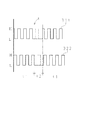
図5は図4に示す回路図の信号を示した図である。
Hereinafter, the best mode for carrying out the present invention will be described with reference to the drawings.
FIG. 1 shows a front view of an actuator used in an in-vehicle air conditioner, for example, as an electric motor with a speed reduction mechanism, and shows an internal configuration with a part of the housing omitted.
FIG. 2 is a side view of the actuator shown in FIG.
FIG. 3 shows a configuration that characterizes the present invention. FIG. 3A is a front view thereof, and FIG. 3B is a side view thereof.
FIG. 4 is a circuit diagram according to the configuration of the present invention. FIG. 4A shows a first embodiment, and FIG. 4B shows a second embodiment.
FIG. 5 is a diagram showing signals of the circuit diagram shown in FIG.
図1および図2によりアクチュエータ1の構成(第一実施例)を説明する。
アクチュエータ1は下ケース2と上ケース3により箱状に形成され、内部に駆動用モータ22、減速歯車列となるウオームギヤ11、第一中間ギヤ12、第二中間ギヤ13および出力軸14cを有する出力ギヤ14、そして印刷配線基板で形成された基板21が収容されている。基板21は減速ギヤの回転を検出するための回路を構成する。
下ケース2はケースの底面を構成する底板2aとその底板2aの外周に形成された外周壁2bにより浅いカップ状に形成され、外周壁2bにはこのアクチュエータ1を各種装置へ取り付けるための取付フランジ2dが設けられている。上ケース3は図を見やすくするため破線でその外形を示し、説明を省略する。
The configuration (first embodiment) of the
The
The
モータ22は取付板22bにより底板2aの所定位置に固定され、モータワイヤ22aにより基板21と電気的に接続される。
このアクチュエータ1の減速歯車列は、モータ22の回転軸22cに取り付けられたウオームギヤ11、第一中間ギヤ12、第二中間ギヤ13および出力ギヤ14で構成されている。第一中間ギヤ12、第二中間ギヤ13はそれぞれ底板2aに形成された支持ボス2i、2hに回転支持されている。
第一中間ギヤ12は大ギヤ12aと小ギヤ12bが一体に形成され、所定の減速比になるよう歯数が決定される。また、第二中間ギヤ13も同様に大ギヤ13aと小ギヤ13bで形成されている。
ウオームギヤ11は第一中間ギヤ12の大ギヤ12aと噛み合い、小ギヤ12bが第二中間ギヤ13の大ギヤ13aと噛み合う。さらに、第二中間ギヤ13は小ギヤ13bが出力ギヤ14の大ギヤ14aと噛み合う。第一中間ギヤ12から出力ギヤ14までは平歯車とピニオンギヤが用いられ、それらの回転軸は底板2aに対し垂直でそれぞれ平行している。
The
The reduction gear train of the
In the first
The
出力ギヤ14には大ギヤ14aと一体に出力軸14cがその回転中心に設けられ、底板2aに設けられた、開孔を有する出力軸ガイド2gにより下ハウジング2に回転支持されている。出力軸14cは開孔からハウジングの外部へ突出されている。出力ギヤ14の出力軸14cと反対側には円柱状の支持部14fが形成され、上ハウジング3により回転支持される。出力軸14cにはDあるいはIカットが設けられ、取り付けられる空気調整装置の弁等を回転駆動させる。
基板21は印刷配線板で、モータへ駆動電流を供給する回路パターンが形成され、また減速歯車や出力ギヤの回転を検出するホールIC31、32が搭載され、そのための回路も形成されている。基板21にはまた、このアクチュエータ1を制御する制御機器からの信号や電源等を接続するコネクタ21bが取り付けられ、下ハウジング2にはコネクタを固定する取付リブ2cが形成されている。
この基板21は、出力ギヤ14の大ギヤ14aと第二中間ギヤ13の大ギヤ13aの間に挟まれるよう配置され、基板取付軸2fにより底板2aに固定されている。磁気センサとしてのホールICが搭載される部分は第二中間ギヤ13が回転軸方向で重なる領域に配置される。
An output shaft 14c is provided at the center of rotation of the
The
The
次に、図3および図4(イ)により本願発明の特徴となる回転検出に関する構成を説明する。
第二中間ギヤ13は出力ギヤ14の大ギヤ14aと噛み合うために円柱状に形成された小ギヤ13bと、小ギヤ13bの片端部に円盤鍔状に形成されたフランジ部13dおよびフランジ部13dの外周に形成され、第一中間ギヤ12と噛み合う大ギヤ13aで形成されている。
フランジ部13dの基板21側には、回転軸と同心に円周方向で複数のNS極が形成された環状磁石16とヨーク板17が取り付けられている。ヨーク板17は環状磁石16とフランジ部13dの間に配置され、環状磁石16の磁束を後述のホールICに作用
させるためのバックヨークとして機能している。本実施例では磁極は24極とし、約15度の着磁開角で環状に磁石を構成している。
Next, a configuration relating to rotation detection, which is a feature of the present invention, will be described with reference to FIG. 3 and FIG.
The second
An
出力ギヤ14は、アクチュエータ1の外方へ突出する出力軸14cと、その出力軸14cに形成されたフランジ部14d、フランジ部14dの外周に形成され第二中間ギヤ13の小ギヤ13bと噛み合う大ギヤ14aおよび上ハウジング3に回転支持される支持部14fで形成されている。
フランジ部14dの第二中間ギヤ13側には、出力軸のDカットやIカットの位置に合わせた凸片18が形成されている。この凸片は樹脂製出力ギヤ14のフランジ部14dに矩形状に突出させて形成している。
基板21は軸方向に対して第二中間ギヤ13と出力ギヤ14の間に位置し、それぞれのフランジ部13d、14dと平行になるよう取り付けられる。軸方向から見て第二中間ギヤ13と出力ギヤ14が重畳する部分には第一開孔21cが設けられ、その近傍にさらに第二開孔21dが設けられている。
The
On the second
The
開孔21c、21dには環状磁石16の磁気を検出して波形整形されたパルス状の検出信号を出力する第一ホールIC31と第二ホールIC32が取り付けられる。このときホールICの位置は第二中間ギヤ13の回転軸を中心として37.5度の開角で、第二中間ギヤ13の回転軸に対し同心円周上に取り付けられる。この位置で、各ホールICは環状磁石16の磁気を同一周期、異なる位相で検出する。
また、基板21には、この突片18の旋回円周上で第二中間ギヤ13の外側に、凸片18により押圧されるスイッチ金具23が取り付けられている。スイッチ金具23はバネ性と導通性のある金属板で、頂部23aを有するほぼ二等辺の山形に形成されている。その一端部23bは基板上の接地パターン21gに接続され、半田付け、リベット等で基板21に固定される。
A
Further, a switch fitting 23 that is pressed by the
スイッチ金具23の他端部23cは接続パターン21e、21fと接触可能な位置に配置され、通常は両パターンより浮いた状態でスイッチ金具23が基板21に固定されている。
出力ギヤ14が回転して凸片18がスイッチ金具23の位置にきたとき、凸片18はスイッチ金具23の二等辺傾斜部から頂部23aを押圧して他端部23cを接続パターン21e、21fに接続させる。
ホールIC31、32は電源31c、32cにより駆動され内部にホール素子と波形整形回路を有するICで、同一周期、異なる位相で環状磁石16の磁極による磁気を検出し矩形波311、322を検出出信号として出力端子31a、32aから出力する。出力端子31a、32aは基板上の印刷配線(図示せず)を介して制御用IC33の入力端子33a、33bに接続されている。接続パターン21e、21fはホールIC31、32の出力端子31a、32aと制御用IC33の入力端子33a、33bの間に設けられている。
制御用ICでは入力された矩形波331、332により第二中間ギヤ13の回転(すなわち出力軸14c)の回転およびその回転方向を検出する。
なお、この制御用IC33は基板21上に配置しても良いし、アクチュエータ1の外部回路へ設け基板21とコネクタ21bを介して接続しても良い。
The
When the
The
In the control IC, the rotation of the second intermediate gear 13 (that is, the output shaft 14c) and the rotation direction thereof are detected by the input rectangular waves 331 and 332.
The
以上の構成による本願発明の減速機構付き電動モータの作用について説明する。図5は上述の実施例に用いられる回路上の信号を現す。
ここで、凸片18がスイッチ金具23の位置にないとき(範囲t1)、ホールIC31、32の出力波形331、332は同一周期で異なる位相の矩形波となる。
凸片18がスイッチ金具23の位置にきてスイッチ金具23を押圧し他端部23cが接続パターン21e、21fに接触すると、ホールICの出力端子31aと32aは接地パターン21gと短絡することになる(範囲t2)。そうすると、短絡した時点tでホールIC31、32の両出力が接地され制御用ICへはL信号が入力される。
凸片18がスイッチ金具23から離れると、他端部23cが接続パターン21e、21fから離れ、ホールIC31、32の両出力は再び矩形波として入力端子33a、33bから制御用IC33へ送られることになる。制御用ICにおいて、所定時間出力波形331、332の入力がLであるとき、その期間は凸片18がスイッチ金具23の位置にあると判断し、その位置を初期位置とするよう設定する。
The operation of the electric motor with a speed reduction mechanism of the present invention having the above configuration will be described. FIG. 5 shows the signals on the circuit used in the embodiment described above.
Here, when the
When the
When the
初期位置が設定された後は、出力波形331、332のパルス数をカウントする等して出力軸が初期位置に対しどのくらい回転したかを検出する。
この構成ではスイッチ金具23の取り付け位置を治具等で正確に位置決めしたり、また出力波形331、332の周波数を高くすることで初期位置を高精度化できる。そのため環状磁石は出力軸ギヤではなく回転数の高い中間ギヤやモータ軸に取り付けると良い。
また、出力ラインが接地される時間(範囲t2)は凸片18の形状で調整できる。例えば凸片18を矩形状にせず先端のとがった山形にすると時間(範囲t2)を短くできる。
After the initial position is set, the number of pulses of the output waveforms 331 and 332 is counted to detect how much the output shaft has rotated with respect to the initial position.
With this configuration, the initial position can be made highly accurate by accurately positioning the mounting position of the switch fitting 23 with a jig or the like, or by increasing the frequency of the output waveforms 331 and 332. For this reason, the annular magnet is preferably attached not to the output shaft gear but to the intermediate gear or motor shaft having a high rotational speed.
The time (range t 2 ) during which the output line is grounded can be adjusted by the shape of the
上述では、ホールIC31、32の出力端子31aと32aを接地させる構成として、スイッチ金具23を接続パターン21e、21fに接触させる機械的構成を示したが、接地させる構成として電気的に行う方法も考えられる。その構成を第二の実施例としてその回路図を図4(ロ)により説明する。
この構成では凸片18の代わりに磁石片を用い、スイッチ金具23のかわりにホールIC34を用いるものである。ホールIC34の取り付け位置はスイッチ金具23と同じ位置で、磁石片も凸片18と同じ位置に取り付ける。磁石片はギヤの回転軸方向にN、S一極ずつ着磁されている。
そして、このホールIC34では磁石片の磁気を検出したときL信号を出力するものとする。ホールICの出力端子34aはダイオードD1、D2を介してそれぞれ接続パターン21e、21fに接続される。
このような構成とすれば、磁石片がホールIC34の位置にきたとき(範囲t2)ホールIC34はL出力となり、制御用IC33へ入力される信号もその間L信号となる。
In the above description, a mechanical configuration in which the switch fitting 23 is brought into contact with the connection patterns 21e and 21f is shown as a configuration for grounding the output terminals 31a and 32a of the
In this configuration, a magnet piece is used instead of the
The
With such a configuration, when the magnet piece comes to the position of the Hall IC 34 (range t 2 ), the
本願発明は例えば上述の構成により制御用IC33の2つの入力(ホールIC31、32の両出力)が同時にLとなることを検出して出力ギヤ14の回転位置を検出し、それをもって出力軸の位置を検出するものである。そして、このような構成とした場合、出力軸14cの位置検出のための信号は従来用いられてきた2つのホールICからの出力だけで済むため、制御用ICに新たな入力端子を設けなくても良い。
また、例えば第一の実施例のように構成すれば、部品として接点金具のみ追加すれば良く、安価で簡単な構成により出力軸の初期位置設定が可能となり、出力軸の位置を検出することが可能となる。
The present invention detects the rotational position of the
Further, for example, if configured as in the first embodiment, it is only necessary to add a contact fitting as a component, the initial position of the output shaft can be set with an inexpensive and simple configuration, and the position of the output shaft can be detected. It becomes possible.
上記実施例は本願発明の構成例を示したもので、権利範囲は実施例に限定されることはない。例えばスイッチ金具は金属板以外でもマイクロスイッチのような既存のものを用いても良い。そして、スイッチを操作する凸片は、出力軸と一体に回転すればよく、例示した実施例のようにギヤのフランジ部に設けても良いし、出力軸に設けて小型のマイクロスイッチ等を操作しても良い。
また、ホールICはアナログ出力のホール素子でも、そのアナログ出力を接地してレベルを変えることが可能である。さらに制御用ICはアクチュエータ内に収納しても良いしアクチュエータ外部に設けても良いことはもちろんである。
The above embodiment shows a configuration example of the present invention, and the scope of right is not limited to the embodiment. For example, switch metal fittings other than metal plates may be used such as micro switches. The convex piece for operating the switch only needs to rotate integrally with the output shaft, and may be provided on the flange portion of the gear as in the illustrated embodiment, or provided on the output shaft to operate a small micro switch or the like. You may do it.
Further, even if the Hall IC is an analog output Hall element, the level can be changed by grounding the analog output. Furthermore, the control IC may be housed in the actuator or provided outside the actuator.
1 アクチュエータ
2 下ハウジング
13 第二中間ギヤ
14 出力ギヤ
14c 出力軸
16 環状磁石
18 凸片
21 基板
23 スイッチ金具
31 第一ホールIC
32 第二ホールIC
DESCRIPTION OF
32 Second Hall IC
Claims (5)
Priority Applications (1)
| Application Number | Priority Date | Filing Date | Title |
|---|---|---|---|
| JP2004338271A JP4114876B2 (en) | 2004-11-24 | 2004-11-24 | Electric motor with reduction mechanism |
Applications Claiming Priority (1)
| Application Number | Priority Date | Filing Date | Title |
|---|---|---|---|
| JP2004338271A JP4114876B2 (en) | 2004-11-24 | 2004-11-24 | Electric motor with reduction mechanism |
Publications (3)
| Publication Number | Publication Date |
|---|---|
| JP2006149134A JP2006149134A (en) | 2006-06-08 |
| JP2006149134A5 JP2006149134A5 (en) | 2007-12-27 |
| JP4114876B2 true JP4114876B2 (en) | 2008-07-09 |
Family
ID=36628170
Family Applications (1)
| Application Number | Title | Priority Date | Filing Date |
|---|---|---|---|
| JP2004338271A Expired - Fee Related JP4114876B2 (en) | 2004-11-24 | 2004-11-24 | Electric motor with reduction mechanism |
Country Status (1)
| Country | Link |
|---|---|
| JP (1) | JP4114876B2 (en) |
Families Citing this family (4)
| Publication number | Priority date | Publication date | Assignee | Title |
|---|---|---|---|---|
| KR101559117B1 (en) * | 2015-05-21 | 2015-10-08 | 디와이오토 주식회사 | Wiper motor apparatus for a vehicle |
| KR102611102B1 (en) * | 2018-11-19 | 2023-12-07 | 미네베아미츠미 가부시키가이샤 | Actuator and Method for controlling thereof and electronic device |
| KR102437290B1 (en) * | 2020-12-22 | 2022-08-30 | 인지컨트롤스 주식회사 | Actuator for vehicle coolant control valve |
| US11906073B2 (en) | 2022-06-21 | 2024-02-20 | Inzicontrols Co., Ltd. | Actuator for vehicle coolant control valve |
Family Cites Families (6)
| Publication number | Priority date | Publication date | Assignee | Title |
|---|---|---|---|---|
| JPH10248212A (en) * | 1997-02-28 | 1998-09-14 | Canon Precision Inc | Motor actuator |
| JP2000136885A (en) * | 1998-11-02 | 2000-05-16 | Matsushita Electric Works Ltd | Geared motor for hot water supply machine |
| JP2002136049A (en) * | 2000-10-19 | 2002-05-10 | Jidosha Denki Kogyo Co Ltd | Motor with position switch |
| JP2002136047A (en) * | 2000-10-19 | 2002-05-10 | Jidosha Denki Kogyo Co Ltd | Motor with position switch |
| JP2002262515A (en) * | 2001-03-02 | 2002-09-13 | Mitsuba Corp | Motor with reduction gear mechanism |
| JP4191509B2 (en) * | 2003-03-05 | 2008-12-03 | 株式会社ミツバ | Motor control method and motor control apparatus |
-
2004
- 2004-11-24 JP JP2004338271A patent/JP4114876B2/en not_active Expired - Fee Related
Also Published As
| Publication number | Publication date |
|---|---|
| JP2006149134A (en) | 2006-06-08 |
Similar Documents
| Publication | Publication Date | Title |
|---|---|---|
| JP4129875B2 (en) | Electric motor with reduction mechanism | |
| US6703732B2 (en) | Electromotor, especially wiper motor, wiping the glass surface of a motor vehicle | |
| RU2212087C2 (en) | Measuring converter | |
| JPWO2003016829A1 (en) | Magnetic micro encoder and micro motor | |
| KR20040030057A (en) | Gear drive unit with speed measurement | |
| US10951147B2 (en) | Actuating device and vehicle steering device comprising an electric engine and a rotor position sensor and a multiturn sensor | |
| WO2001063632A1 (en) | Rotary switch mechanism for operation panel | |
| JP4430110B2 (en) | Switching flap device | |
| JP4114876B2 (en) | Electric motor with reduction mechanism | |
| EP1342647A2 (en) | Rotation-angle detecting device capable of precisely detecting absolute angle | |
| JP2006029792A (en) | Anisotropic magnetoresistive element and turning angle detector using the same | |
| JP4111452B2 (en) | Electric motor with reduction mechanism | |
| JP4925389B2 (en) | Encoder | |
| JP2007230413A (en) | Torque sensor | |
| JP4690710B2 (en) | Electric motor with reduction mechanism | |
| KR100460423B1 (en) | detection apparatus for steering angle in vehicle | |
| JP2008186755A (en) | Input device | |
| WO2018173571A1 (en) | Power steering device | |
| JP2004266946A (en) | Motor actuator | |
| JP2006327254A (en) | Position initialization method of electric actuator | |
| JPH08285878A (en) | Speed sensor | |
| KR100458191B1 (en) | detection apparatus for steering angle in vehicle | |
| JP5006818B2 (en) | Position detecting device and actuator | |
| JP5026838B2 (en) | motor | |
| JP3829331B2 (en) | Angle detector |
Legal Events
| Date | Code | Title | Description |
|---|---|---|---|
| A521 | Written amendment |
Free format text: JAPANESE INTERMEDIATE CODE: A523 Effective date: 20071114 |
|
| A621 | Written request for application examination |
Free format text: JAPANESE INTERMEDIATE CODE: A621 Effective date: 20071114 |
|
| A871 | Explanation of circumstances concerning accelerated examination |
Free format text: JAPANESE INTERMEDIATE CODE: A871 Effective date: 20071114 |
|
| A975 | Report on accelerated examination |
Free format text: JAPANESE INTERMEDIATE CODE: A971005 Effective date: 20071206 |
|
| A131 | Notification of reasons for refusal |
Free format text: JAPANESE INTERMEDIATE CODE: A131 Effective date: 20071210 |
|
| A521 | Written amendment |
Free format text: JAPANESE INTERMEDIATE CODE: A523 Effective date: 20080122 |
|
| TRDD | Decision of grant or rejection written | ||
| A01 | Written decision to grant a patent or to grant a registration (utility model) |
Free format text: JAPANESE INTERMEDIATE CODE: A01 Effective date: 20080411 |
|
| A61 | First payment of annual fees (during grant procedure) |
Free format text: JAPANESE INTERMEDIATE CODE: A61 Effective date: 20080411 |
|
| FPAY | Renewal fee payment (event date is renewal date of database) |
Free format text: PAYMENT UNTIL: 20110425 Year of fee payment: 3 |
|
| R150 | Certificate of patent or registration of utility model |
Ref document number: 4114876 Country of ref document: JP Free format text: JAPANESE INTERMEDIATE CODE: R150 Free format text: JAPANESE INTERMEDIATE CODE: R150 |
|
| FPAY | Renewal fee payment (event date is renewal date of database) |
Free format text: PAYMENT UNTIL: 20110425 Year of fee payment: 3 |
|
| FPAY | Renewal fee payment (event date is renewal date of database) |
Free format text: PAYMENT UNTIL: 20120425 Year of fee payment: 4 |
|
| R250 | Receipt of annual fees |
Free format text: JAPANESE INTERMEDIATE CODE: R250 |
|
| FPAY | Renewal fee payment (event date is renewal date of database) |
Free format text: PAYMENT UNTIL: 20130425 Year of fee payment: 5 |
|
| R250 | Receipt of annual fees |
Free format text: JAPANESE INTERMEDIATE CODE: R250 |
|
| FPAY | Renewal fee payment (event date is renewal date of database) |
Free format text: PAYMENT UNTIL: 20140425 Year of fee payment: 6 |
|
| R250 | Receipt of annual fees |
Free format text: JAPANESE INTERMEDIATE CODE: R250 |
|
| R250 | Receipt of annual fees |
Free format text: JAPANESE INTERMEDIATE CODE: R250 |
|
| R250 | Receipt of annual fees |
Free format text: JAPANESE INTERMEDIATE CODE: R250 |
|
| R250 | Receipt of annual fees |
Free format text: JAPANESE INTERMEDIATE CODE: R250 |
|
| R250 | Receipt of annual fees |
Free format text: JAPANESE INTERMEDIATE CODE: R250 |
|
| R250 | Receipt of annual fees |
Free format text: JAPANESE INTERMEDIATE CODE: R250 |
|
| R250 | Receipt of annual fees |
Free format text: JAPANESE INTERMEDIATE CODE: R250 |
|
| LAPS | Cancellation because of no payment of annual fees |