JP4101812B2 - Molecular structure compound identification system - Google Patents
Molecular structure compound identification system Download PDFInfo
- Publication number
- JP4101812B2 JP4101812B2 JP2005032530A JP2005032530A JP4101812B2 JP 4101812 B2 JP4101812 B2 JP 4101812B2 JP 2005032530 A JP2005032530 A JP 2005032530A JP 2005032530 A JP2005032530 A JP 2005032530A JP 4101812 B2 JP4101812 B2 JP 4101812B2
- Authority
- JP
- Japan
- Prior art keywords
- test sample
- ray
- molecular structure
- structure composite
- identification apparatus
- Prior art date
- Legal status (The legal status is an assumption and is not a legal conclusion. Google has not performed a legal analysis and makes no representation as to the accuracy of the status listed.)
- Expired - Fee Related
Links
Images


Description
本発明は、医薬品結晶等の分子状態に関する物性評価をX線回折と赤外光・可視光・紫外光の何れにより行う分子構造複合同定装置に関する。 The present invention relates to a molecular structure composite identification apparatus that performs physical property evaluation on a molecular state of a pharmaceutical crystal or the like by any of X-ray diffraction and infrared light / visible light / ultraviolet light.
「医薬品結晶の分子状態に関する物性評価(12)」について、(PHARM TECH JAPAN ●Vol.18 No.10(2002) pp.81-96)において知られている。第92頁には、「図7に示したような96well上で結晶化した試料は、自動でBirefringence Stationに移動して、複屈折の正負から結晶か非晶質かの状態を判定し、確認することができるようになっている。そして、96well上で結晶が確認された試料については、図8に示すXRD Stationにてwell上のそれぞれの試料は自動アライメントされ、X線回折パターンの測定が行われる。例えば、図9に示されているようなフェニルブタゾンのX線回折パターンが、Well C8, Well B8, Well A9として確認される。同様に、Raman Stationにおいてはラマンスペクトルが測定され、図10は、図9に示されたフェニルブタゾンのスペクトルであり、Well A8, Well D5, Well F5, Well G11として示されている。また、Melting Point Stationにおいては、温度による結晶の相移転なども自動測定されるようになっている。」と記載されている。 “PHARM TECH JAPAN ● Vol.18 No.10 (2002) pp.81-96) is known for“ physical property evaluation on molecular state of pharmaceutical crystals (12) ”. On page 92, “A sample crystallized in 96 wells as shown in FIG. 7 automatically moves to Birefringence Station, and determines whether it is crystalline or amorphous based on the birefringence sign. For the samples whose crystals were confirmed on 96 wells, each sample on the wells was automatically aligned at the XRD Station shown in FIG. For example, the X-ray diffraction pattern of phenylbutazone as shown in Fig. 9 is confirmed as Well C8, Well B8, Well A9. Similarly, Raman spectrum is measured at Raman Station, Fig. 10 shows the spectrum of phenylbutazone shown in Fig. 9 and is shown as Well A8, Well D5, Well F5, Well G11, and at Melting Point Station, the phase transition of crystals with temperature, etc. Is also automatically measured "
また、X線回折装置を備えた化学反応処理装置としては、特開2001−219052号公報で知られている。 Moreover, as a chemical reaction processing apparatus provided with the X-ray diffraction apparatus, it is known by Unexamined-Japanese-Patent No. 2001-219052.
また、X線回折を用いる異なる物質のライブラリーを特徴つける装置及び方法としては、US 6,371,640 B1において知られている。 An apparatus and method for characterizing a library of different substances using X-ray diffraction is known from US 6,371,640 B1.
上述したように、上記非特許文献1では、XRD StationでX線回折パターンの測定が行われ、同様に、Raman Stationにおいてはラマンスペクトルが測定され、また、Melting Point Stationにおいては、温度による結晶の相移転なども自動測定されるようになっていると記載されている。このように非特許文献1に記載されているように別々のステーションでX線回折パターン測定、ラマンスペクトル測定、温度による結晶の相移転測定を行うのでは、試料数(再結晶化条件数の積)と測定数の積となり、データ数が増大しデータ管理が非常に複雑になると共にWellをその都度各ステーションにおいて繰り返して位置決め制御する必要が生じ位置決め制御が非常に複雑であった。
As described above, in Non-Patent
このように、上記非特許文献1、特許文献1および2にの何れにも、連続的或いは位置的に離れて多数の被検試料が形成された被検試料載置板をステージ上に保持した状態で、上記被検試料のX線回折分析と、ラマン散乱分析、反射赤外線分析、反射紫外線分析及び試料反射像による分析のいずれかあるいは複数を同時あるいは連続的に行って、測定数を減らすことによってデータ数を低減し、非破壊検査による検査・試験パスを単純化して、確実にしかも高速で行うことについては考慮されていなかった。
As described above, in both
本発明の目的は、上記課題を解決すべく、連続的或いは位置的に離れて多数の被検試料が形成された被検試料載置板をステージ上に保持した状態で、上記被検試料のX線回折分析と、試料反射像、ラマン散乱分析、反射赤外線分析及び反射紫外線分析による分析のいずれかあるいは複数を同時あるいは連続的に行うことによって非破壊検査による検査パスの短縮を図り例えば薬剤開発期間の短縮、しいては製造・品質の安定化を図った分子構造複合同定装置及びその方法を提供することにある。 The object of the present invention is to solve the above-mentioned problems, in a state where a test sample mounting plate on which a large number of test samples are formed on a stage is held on a stage. X-ray diffraction analysis, sample reflection image, Raman scattering analysis, reflected infrared analysis, and reflected ultraviolet analysis can be performed simultaneously or sequentially to shorten the inspection path by nondestructive inspection, for example, drug development An object of the present invention is to provide a molecular structure composite identification apparatus and method for shortening the period, and stabilizing production and quality.
上記目的を達成するために、本発明は、被検試料載置板に載置された同じ被検試料に対して0.5mm以下の直径に制限したX線ビームと赤外線・可視光・紫外線の何れか一つのあるいは複数の波長ビームを照射する照射光学系と、前記被検試料から得られるX線回折パターン及び前記被検試料から放出される反射光又は散乱光を検出する検出光学系とを備え、前記被検試料から同時または連続して少なくともX線回折パターンのデータ及び反射光学像のデータを取得することを特徴とする分子構造複合同定装置である。 In order to achieve the above object, the present invention provides an X-ray beam limited to a diameter of 0.5 mm or less and infrared / visible / ultraviolet light with respect to the same test sample placed on the test sample mounting plate. An irradiation optical system for irradiating any one or a plurality of wavelength beams, and an X-ray diffraction pattern obtained from the test sample and a detection optical system for detecting reflected light or scattered light emitted from the test sample A molecular structure composite identification apparatus characterized in that at least X-ray diffraction pattern data and reflection optical image data are acquired simultaneously or successively from the test sample.
また、本発明は、複数の被検試料を載置した被検試料載置板と、該被検試料載置板の位置を調整可能に保持する試料保持機構と、X線ビームを発生するX線発生部と、該X線発生部から発生したX線ビームの照射・非照射を制御するシャッター装置と、可視光の波長ビームを出射する照明光源と、前記シャッター装置を通して照射されるX線ビームを0.5mm以下の直径に制限して被検試料に照射するX線光学素子と、前記照明光源から出射された可視光の波長ビームを前記X線光学素子で照射する前記被検試料に集光して照射し、該被検試料から放出される反射光又は散乱光を集光する集光光学系と、前記被検試料を挟んで前記X線光学素子と相対して設置され、前記被検試料からのX線回折を検出するX線検出器と、前記集光光学系で集光された反射光又は散乱光を受光して信号として検出する受光装置を含む検出光学系とを備え、前記X線検出器から被検試料からのX線回折パターンのデータを取得し、前記検出光学系の受光装置から被検試料からの反射光学像のデータを前記X線回折パターンのデータ取得と同時若しくは連続して取得することを特徴とする分子構造複合同定装置である。 The present invention also provides a test sample mounting plate on which a plurality of test samples are mounted, a sample holding mechanism for holding the position of the test sample mounting plate in an adjustable manner, and an X-ray beam X A ray generator, a shutter device that controls irradiation / non-irradiation of an X-ray beam generated from the X-ray generator, an illumination light source that emits a wavelength beam of visible light, and an X-ray beam emitted through the shutter device The X-ray optical element that irradiates the test sample with a diameter of 0.5 mm or less and the test sample that irradiates the visible light wavelength beam emitted from the illumination light source with the X-ray optical element. A condensing optical system that irradiates and collects reflected or scattered light emitted from the test sample, and is placed opposite to the X-ray optical element with the test sample sandwiched therebetween. An X-ray detector for detecting X-ray diffraction from the specimen and the condensing optical system A detection optical system including a light receiving device that receives the reflected or scattered light and detects it as a signal, obtains data of an X-ray diffraction pattern from a sample to be detected from the X-ray detector, and performs the detection A molecular structure composite identification apparatus characterized in that data of a reflected optical image from a test sample is acquired simultaneously or successively with the acquisition of data of the X-ray diffraction pattern from a light receiving device of an optical system.
また、本発明は、複数の被検試料を載置した被検試料載置板と、該被検試料載置板の位置を調整可能に保持する試料保持機構と、X線ビームを発生するX線発生部と、該X線発生部から発生したX線ビームの照射・非照射を制御するシャッター装置と、赤外線・可視光・紫外線の何れか一つあるいは複数の波長ビームを出射する照明光源と、前記シャッター装置を通して照射されたX線ビームを0.5mm以下の直径に制限して被検試料に照射するX線光学素子と、前記照明光源から出射された前記一つあるいは複数の波長ビームを前記X線光学素子で照射する前記被検試料に集光して照射し、該被検試料から放出される反射光又は散乱光を集光する集光光学系と、前記被検試料を挟んで前記X線光学素子と相対して設置され、前記被検試料からのX線回折を検出するX線検出器と、前記集光光学系で集光された反射光又は散乱光を受光して信号として検出する受光装置を含む検出光学系とを備え、前記X線検出器から被検試料からのX線回折パターンのデータを取得し、前記検出光学系の受光装置から被検試料からの反射光学像、ラマン散乱スペクトル、反射赤外線スペクトル及び反射紫外線スペクトルのいずれか一つのあるいは複数のデータを前記X線回折パターンのデータ取得と同時若しくは連続して取得することを特徴とする分子構造複合同定装置である。 The present invention also provides a test sample mounting plate on which a plurality of test samples are mounted, a sample holding mechanism for holding the position of the test sample mounting plate in an adjustable manner, and an X-ray beam X A ray generator, a shutter device that controls irradiation / non-irradiation of the X-ray beam generated from the X-ray generator, and an illumination light source that emits one or a plurality of wavelength beams of infrared rays, visible light, and ultraviolet rays An X-ray optical element that irradiates a test sample with an X-ray beam irradiated through the shutter device limited to a diameter of 0.5 mm or less, and the one or more wavelength beams emitted from the illumination light source. A condensing optical system for condensing and irradiating the test sample irradiated by the X-ray optical element and collecting reflected light or scattered light emitted from the test sample, and the test sample sandwiched between The test sample is installed opposite to the X-ray optical element, An X-ray detector for detecting X-ray diffraction from the above and a detection optical system including a light receiving device that receives reflected light or scattered light collected by the condensing optical system and detects it as a signal. X-ray diffraction pattern data from the test sample is acquired from the line detector, and any one of the reflected optical image, Raman scattering spectrum, reflected infrared spectrum, and reflected ultraviolet spectrum from the test sample from the light receiving device of the detection optical system The molecular structure composite identification apparatus is characterized in that one or a plurality of data is acquired simultaneously or continuously with data acquisition of the X-ray diffraction pattern.
また、本発明は、前記分子構造複合同定装置において、前記被検試料載置板上に載置された各被検試料の溶解性(溶解点)を測定する手段を備え、該手段によって各被検試料の溶解性のデータを取得することを特徴とする。 In the molecular structure composite identification apparatus, the present invention further comprises means for measuring the solubility (dissolution point) of each test sample placed on the test sample placing plate. It is characterized by obtaining solubility data of a test sample.
また、本発明は、前記分子構造複合同定装置において、更に、前記被検試料載置板上に載置された被検試料の位置座標を連続的或いは離散的に制御して移動させる移動装置を備えたことを特徴とする。
また、本発明は、前記分子構造複合同定装置において、前記X線光学素子を、内径が0.5mm以下の管状の反射X線キャピラリで構成したことを特徴とする。
また、本発明は、前記分子構造複合同定装置において、前記X線光学素子を、反射されたX線が前記被検試料に収束するように表面形状を形成したX線反射鏡で構成したことを特徴とする。
また、本発明は、前記分子構造複合同定装置において、前記集光光学系を、X線ビームを通過させるための穴が設けられた反射鏡で構成したことを特徴とする。
また、本発明は、前記分子構造複合同定装置において、前記集光光学系を、X線ビームを通過させるための穴が設けられた光学レンズで構成したことを特徴とする。
また、本発明は、前記分子構造複合同定装置において、前記被検試料載置板は、多数の被検試料が連続的或いは位置的に離れて載置されて構成されることを特徴とする。
In the molecular structure composite identification apparatus, the present invention further includes a moving device that moves the position coordinates of the test sample placed on the test sample placing plate by controlling the position coordinates continuously or discretely. It is characterized by having.
In the molecular structure composite identification apparatus, the present invention is characterized in that the X-ray optical element is formed of a tubular reflective X-ray capillary having an inner diameter of 0.5 mm or less.
In the molecular structure composite identification apparatus according to the present invention, the X-ray optical element may be constituted by an X-ray reflecting mirror having a surface shape so that reflected X-rays converge on the test sample. Features.
Further, the present invention is characterized in that, in the molecular structure composite identification apparatus, the condensing optical system is configured by a reflecting mirror provided with a hole for allowing an X-ray beam to pass therethrough.
Further, the present invention is characterized in that, in the molecular structure composite identification apparatus, the condensing optical system is constituted by an optical lens provided with a hole for allowing an X-ray beam to pass therethrough.
In the molecular structure composite identification apparatus according to the present invention, the test sample mounting plate is configured by mounting a large number of test samples on a continuous or positional basis.
また、本発明は、前記分子構造複合同定装置において、前記被検試料のX線回折パターンの測定と反射光学像の測定の他に、ラマン散乱スペクトルの測定、反射赤外線スペクトルの測定及び反射赤外線スペクトルの測定を行う場合には、測定ユニットを交換することにより特定のあるいは複数のスペクトルのデータを取得できるように切り替えることを特徴とする。
また、本発明は、前記分子構造複合同定装置において、前記X線検出器を、直径20mm以上80mm以下の検出可能領域を持つX線検出デバイスと、該X線検出デバイスの試料側に被検試料を照射するX線ビームの延長線上の位置を中心として設置された円形スリットと、特定の回折線のみを前記X線検出デバイスに照射するように透過させるための直線移動型位置調整機構とを備えて構成したことを特徴とする。
また、本発明は、前記分子構造複合同定装置において、前記X線検出器として2次元のX線検出器を用い、被検試料を照射するX線ビームの延長線上の位置を中心とする円環状領域毎に積算した数値を求めることにより被検試料のX線回折パターンのデータを取得することを特徴とする。
Further, the present invention provides the molecular structure composite identification apparatus, in addition to the measurement of the X-ray diffraction pattern and the reflection optical image of the test sample, the measurement of the Raman scattering spectrum, the measurement of the reflected infrared spectrum, and the reflected infrared spectrum. When the measurement is performed, the measurement unit is switched so that data of a specific spectrum or a plurality of spectra can be acquired by exchanging the measurement unit.
In the molecular structure composite identification apparatus, the present invention may be configured such that the X-ray detector includes an X-ray detection device having a detectable region having a diameter of 20 mm to 80 mm, and a test sample on the sample side of the X-ray detection device. A circular slit installed around the position on the extended line of the X-ray beam, and a linear movement type position adjusting mechanism for transmitting only a specific diffraction line so as to irradiate the X-ray detection device. It is characterized by being configured.
In the molecular structure composite identification apparatus according to the present invention, a two-dimensional X-ray detector is used as the X-ray detector, and an annular shape centering on a position on an extended line of the X-ray beam that irradiates the test sample is used. The X-ray diffraction pattern data of the test sample is obtained by obtaining a numerical value integrated for each region.
また、本発明は、前記分子構造複合同定装置において、前記被検試料載置板には少なくとも個体識別用符号若しくは情報を付与して構成し、該付与された個体識別用符号若しくは情報を機械的・光学・電磁波・磁気の何れかあるいは複数の方法によって読み取る読み取り装置を備えたことを特徴とする。
また、本発明は、前記分子構造複合同定装置において、被検試料載置板に付与された個体識別用符号若しくは情報と、被検査試料載置板上における各被検試料の位置座標若しくは位置情報とを、各被検試料から取得されるデータに対応させて管理することを特徴とする。
また、本発明は、前記分子構造複合同定装置において、被検試料載置板上に載置された各被検試料の識別情報を、各被検試料から取得されるデータに対応させて記憶する記憶装置を備えたことを特徴とする。
また、本発明は、前記分子構造複合同定装置において、被検試料載置板上に載置された各被検試料の識別情報及び各被検試料の形成条件を、各被検試料から取得されるデータに対応させて記憶する記憶装置を備えたことを特徴とする。
Further, the present invention provides the molecular structure composite identification apparatus, wherein at least the individual identification code or information is assigned to the test sample mounting plate, and the assigned individual identification code or information is mechanically A reading device is provided that reads by any one of a plurality of methods such as optics, electromagnetic waves, and magnetism.
Further, the present invention provides the molecular structure composite identification apparatus, wherein the individual identification code or information given to the test sample mounting plate and the position coordinates or position information of each test sample on the test sample mounting plate Are managed in correspondence with data acquired from each test sample.
In the molecular structure composite identification apparatus, the present invention stores identification information of each test sample placed on the test sample placement plate in correspondence with data acquired from each test sample. A storage device is provided.
Further, in the molecular structure composite identification apparatus, the present invention acquires the identification information of each test sample placed on the test sample mounting plate and the formation conditions of each test sample from each test sample. And a storage device that stores data corresponding to the data.
また、本発明は、前記分子構造複合同定装置において、複数枚の被検試料載置板を保管する保管用試料ホルダーと、該保管用試料ホルダーと前記試料保持機構との間で前記被検試料載置板を自動的に交換する交換装置とを備え、一枚の被検試料載置板に対する測定が終了する毎に、保管用試料ホルダー中の被検試料載置板を前記交換装置により前記試料保持機構へと順次あるいは指定された順序で交換することを特徴とする。 In the molecular structure composite identification apparatus, the present invention provides a storage sample holder for storing a plurality of test sample mounting plates, and the test sample between the storage sample holder and the sample holding mechanism. An exchange device for automatically exchanging the placement plate, and each time the measurement for one test sample placement plate is completed, the test device placement plate in the storage sample holder is moved by the exchange device. It is characterized in that the sample holding mechanism is exchanged sequentially or in a designated order.
また、本発明は、前記分子構造複合同定装置において、各被検試料から取得されるデータとして、X線回折パターン、ラマン散乱スペクトル、反射赤外線スペクトル、反射紫外線スペクトル及び反射光学像の何れかあるいは複数のデータであることを特徴とする。 In the molecular structure composite identification apparatus, the present invention may be any one or more of an X-ray diffraction pattern, a Raman scattering spectrum, a reflected infrared spectrum, a reflected ultraviolet spectrum, and a reflected optical image as data acquired from each test sample. It is the data of this.
本発明によれば、多数の被検試料に対してX線回折と赤外光・可視光・紫外光・ラマン散乱の何れか一つあるいは複数とを同時又は連続的に行って間違いが生じることなく正確に且つ効率良く分子構造について複合同定を行うことができる。 According to the present invention, errors occur when X-ray diffraction and one or more of infrared light, visible light, ultraviolet light, and Raman scattering are performed simultaneously or sequentially on a large number of test samples. It is possible to perform complex identification of the molecular structure accurately and efficiently.
本発明に係る分子構造複合同定装置及びその方法の実施の形態について図面を用いて説明する。 Embodiments of a molecular structure composite identification apparatus and method according to the present invention will be described with reference to the drawings.
[第1の実施の形態]
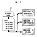
まず、本発明に係る分子構造複合同定装置の第1の実施の形態について図1及び図2を用いて説明する。16は、多数の被検試料17が連続的あるいは位置的に離れてセル又はウエルとして載置(形成)され、個体識別用符号若しくは情報(例えばID番号)18が付与された被検試料載置板(被検試料セル又はウエル付き試料プレート)で、試料保持機構(試料搭載台)13によって水平方向に向けて保持される。その結果、所定の被検試料17がビーム軸に位置合わせられるように移動装置(ステージ)14によって試料保持機構13を介して被検試料載置板16が移動させられる。多数の被検試料17としては、薬効成分を再結晶化条件(溶媒組成、溶媒濃度、溶媒温度、温度履歴、雰囲気、他)で再結晶化された試料が考えられる。その場合、図2に示す本発明に係る分子構造複合同定装置20が行う統合非破壊検査21としては、結晶形態、多形解析、結合解析などがある。結晶形態(針状結晶、板状結晶、その外の塊状結晶等)については、可視光の光学像によって検査することができる。多形解折(規則的な原子の配列構造が異なる多形などの結晶解析)については、X線回折スペクトルによって検査することができる。結合解析(官能基程度の大きさの基本構造解析)については、ラマン散乱・赤外線・紫外線スペクトル(主としてラマン散乱スペクトル)によって検査することが可能となる。
[First Embodiment]
First, a first embodiment of a molecular structure composite identification apparatus according to the present invention will be described with reference to FIGS.
また、被検試料載置板16に付与された個体識別用符号若しくは情報(例えばID番号)18は、機械的・光学・電磁波・磁気の何れかあるいは複数の方法によって、全体制御部15に有線若しくは無線で接続された読み取り装置19により読み取られ、この符号若しくは情報と移動装置(ステージ)14から検出される被検試料載置板16上の位置(位置座標)とから全体制御部15は被検試料17を識別できるよう構成される。
Further, an individual identification code or information (for example, an ID number) 18 assigned to the test
ところで、予め、被検試料載置板に付与された個体識別用符号若しくは情報(例えばID番号)と、被検試料載置板上の被検試料の位置座標若しくは位置情報と、被検試料を形成した被検試料形成条件とを入力手段(記録媒体やネットワークも含む)を用いて入力されて記憶装置15cには格納しておくものとする。
By the way, the individual identification code or information (for example, ID number) given to the test sample mounting plate in advance, the position coordinates or position information of the test sample on the test sample mounting plate, and the test sample The formed test sample forming conditions are input using an input means (including a recording medium and a network) and stored in the
分子構造複合同定装置30は、装置筐体の底面方向にX線を照射できるように装置上部に設置されたX線発生部1と、試料の可視光照明光源2と、可視光の光学像を取得する試料観察カメラ3と、被検試料17からの散乱光や反射光を集光する集光光学系11としての対物鏡(カセグレーン反射光学系)11aと、試料のラマン励起用レーザー光源22と、ハーフミラー4a、4cと、全反射ミラー4bと、該ミラー4a〜4cや対物鏡11a等を保持するマウント部4と、ラマン(赤外・紫外)光受光装置5と、X線ビームを被検試料17に対して照射・非照射するX線遮断装置(X線シャッター装置)6と、被検試料へ照射されるX線ビームを0.5mm程度以下の直径に制限するX線光学素子12としてのX線キャピラリ(内径が0.5mm程度以下であり、X線をほぼ全反射可能な表面状態に調整された管状の全反射X線キャピラリ)12aと、ラマン(赤外線・紫外線)光分光装置7と、X線発生部用電源装置8と、リングシャッタ10を有し、X線ビーム軸方向に位置調整可能なX線検出器9と、データ処理部15aを有する全体制御部15と、全体制御部15に接続された表示装置15bと、被検試料載置板16上にセル又はウエルとして載置された多数の被検試料17に対応させて統合非破壊検査結果が記憶される記憶装置15cと、被検試料載置板16に付与された個体識別用符号若しくは情報(例えばID番号)18を読み取る読み取り装置19とで構成される。なお、集光光学系11としての対物鏡11a及びミラー4bには、X線光学素子12としてのX線キャピラリ12aを設置するための穴が穿設されている。
The molecular structure
X線回折パターンを取得するX線検出器9は、前記被検試料からのX線回折検出に直径20mm程度以上80mm程度以下の検出可能領域を持つX線検出デバイス(X線シンチレーションカウンタ)9aと、該X線検出デバイスの試料側に被検試料を照射するX線ビームの延長線上の位置を中心として設置されたスリット9bと、特定の回折線のみを前記X線検出デバイス9aに照射するように透過させるための直線移動型位置調整機構21とを備えて構成される。
An
多数の被検試料17が設置された被検試料載置板16は、全体制御部15からの指令に基づいて、保持機構13を介して移動装置14によって移動して各被検試料がビーム軸に位置するように位置決めされる。その結果、全体制御部15は、被検試料載置板上の被検試料の位置座標が連続的或いは離散的に移動装置14から得られることになり、記憶装置15cに被検試料の位置座標若しくは位置情報として登録されることになる。同時にX線発生部用電源装置8によって供給された電源によってX線発生部1からはXビームが出射される。全体制御部15からの指令で、X線遮断装置6が開いてX線ビームがX線光学素子12としてのX線キャピラリ12aにより0.5mm程度以下の直径に絞られて被検試料に照射される。該被検試料17に照射されたX線は被検試料の結晶による回折により直進せず、スリットを通過してX線検出器9により検出される。即ち、被検試料17からの円錐状の特定のX線回折パターン20は、スリット9bとリングシャッタ10との隙間(円環状領域)を通してX線検出デバイス9aによって検出される。このように、特定のX線回折パターンのデータは、直線移動型位置調整機構21をX線ビーム軸方向に調整することによって取得される。また、前記X線検出器9として2次元の位置敏感型X線検出器を用い、例えばデータ処理部15aにおいて、2次元の位置敏感型X線検出器から検出される値の内、被検試料を照射するX線ビームの延長線上の位置を中心とする円環状領域(円周領域)毎に積算した数値を求めることによりX線回折パターンのデータを取得するも可能となる。
The test
全体制御部15からの指令に基づいて同時に又は連続してX線回折した同じ被検試料17には、可視光照明光源2及び/又はラマン(赤外線・紫外線)光照明光源22が点灯(シャッタを開閉させても良い。)されて可視光及び/又はラマン光が照射される。即ち、可視光照明光源2で発生する可視光は、マウント4内部に設置されたハーフミラー4aで反射され、全反射ミラー4b及び対物鏡11aを通して被検試料17を照射する。可視光照射による被検試料17からの反射光は対物鏡11aにより集光され、全反射ミラー4bにより全反射され、ハーフミラー4aを通過し、ハーフミラー4cで反射されて試料観察カメラ3により結晶形態を示す被検試料の反射光学像のデータを同時に又は連続して取得され、全体制御部15のデータ処理部15aに入力され、表示できる画像データとして蓄えられる。
A visible
さらに、ラマン励起用レーザー光源22で発生されたレーザー光は光ファイバー23を通してマウント4に導かれ、ハーフミラー4c及び4aを通過して、全反射ミラー4b及び対物鏡11aを通してX線回折した同じ被検試料17に照射される。レーザー光の照射により被検試料で生じたラマン散乱光は対物鏡11aで集光され、全反射ミラー4bで反射され、ハーフミラー4a及び4cを透過した後、ラマン(赤外・紫外)光受光装置5に導入され、その後ラマン(赤外・紫外)光分光装置7に導入され、結合解析(官能基程度の大きさの基本構造解析)を示すラマン散乱(赤外線・紫外線)スペクトルデータが同時に又は連続して取得され、全体制御部15のデータ処理部15aに入力され、表示できるスペクトルデータとして蓄えられる。
Furthermore, the laser beam generated by the Raman excitation
次に、物質のX線による同定方法について具体的に説明する。X線発生源1で発生したX線はX線キャピラリ12aを通して細束に整形され、被検試料17を照射する。被検試料が結晶の場合Braggの法則として知られる次の(1)式が成り立つときのみX線が回折する。
Next, a method for identifying a substance by X-ray will be specifically described. The X-rays generated by the
2dsin θ=λ (1)
ここで、λはX線発生源1で発生したX線の波長、dは被検試料の結晶の格子面の面間隔、θは被検試料に入射するX線と回折に関与する格子面の成す角度である。θは一般には入射角と言われる。回折線の方向は格子面で反射される形となるので、入射X線に対して2倍の入射角2θの方向に出て行く。微細な結晶がランダムな方向に向いている被検試料では、入射X線の進行方向に対して角度2θの円錐形状に回折X線が得られる。
2dsin θ = λ (1)
Here, λ is the wavelength of the X-ray generated by the
被検試料の結晶の原子配列により格子面が異なるため、一般的にこの2θと回折X線の強さのパターンを測定することにより、被検試料の物質特有の回折パターンを得ることが出来る。また、既知の物質の回折パターンと照合することで、被検試料の物質の同定が可能であり、ここで用いるX線回折手法である。 Since the lattice plane differs depending on the atomic arrangement of the crystal of the test sample, generally, a diffraction pattern peculiar to the substance of the test sample can be obtained by measuring the intensity pattern of 2θ and diffraction X-rays. In addition, it is possible to identify the substance of the test sample by collating with the diffraction pattern of the known substance, and this is the X-ray diffraction technique used here.
このX線回折パターンを効率よく測定するため、本発明では図6に示すような装置の構成とした。図6においてX線キャピラリ12aを通過したX線は被検試料17を照射する。被検試料から距離L離れた位置に半径Dの円形のX線通過部51を設けたスリット52(9b)を設置する。スリット52はタングステン(W)やタンタル(Ta)等の重金属を用いてX線通過部51以外の部位はX線を遮蔽する役目をもつ。これによりLとDと回折角度θとの関係は次の(2)式で表される。
In order to efficiently measure this X-ray diffraction pattern, the present invention is configured as shown in FIG. In FIG. 6, X-rays that have passed through the X-ray capillary 12 a irradiate the
tan 2θ=D/L (2)
ここで、スリット52の後方にシンチレーションカウンタ等のX線検出器53を設置する。Lを変化させながらX線検出器53の出力との関係をデータ処理部15aにおいて記録することにより、被検試料の結晶のX線回折パターンを測定することができる。
tan 2θ = D / L (2)
Here, an
図6ではX線ビームを水平に描いているが、本実施例では被検試料17を水平に載置する必要性からX線ビームを垂直としている。
In FIG. 6, the X-ray beam is drawn horizontally, but in this embodiment, the X-ray beam is set vertical because of the necessity of placing the
X線検出器をCCD等の2次元ピクセル検出器とし、スリット52を省略することが可能である。2次元ピクセル検出器では微細な検出素子が2次元に多数配置されるので、微小部分毎のX線を検出することができる。このため、X線回折パターンは図7に示すように入射X線の延長方向の2次元ピクセル検出器上位置を中心Cとした同心円状となる。
The X-ray detector can be a two-dimensional pixel detector such as a CCD, and the
2次元ピクセル検出器を用いる場合、X線回折強度I(2θ)は次の(3)式で表される範囲の各ピクセルの検出強度の和で求められる。 When a two-dimensional pixel detector is used, the X-ray diffraction intensity I (2θ) is obtained by the sum of the detection intensities of the respective pixels in the range represented by the following equation (3).
I(2θ)=ΣI(x,y):D−Δ<SQRT(x2+y2)<D+Δ (3)
ここで、DはC(0,0)を中心とした同心円の半径、I(x,y)はC(0,0)を原点としたときの座標(x,y)のピクセルの検出X線強度、Δは検出器の窓幅に想到するもので、2Δが回折X線の幅に相当する。
I (2θ) = ΣI (x, y): D−Δ <SQRT (x 2 + y 2 ) <D + Δ (3)
Here, D is the radius of a concentric circle centered on C (0,0), and I (x, y) is a detected X-ray of the pixel at coordinates (x, y) when C (0,0) is the origin. The intensity, Δ, corresponds to the detector window width, and 2Δ corresponds to the width of the diffracted X-ray.
実際の測定系では、被検試料17の結晶を透過した強度の大きいX線が検出器に入射しないように、Cの位置に重金属で構成されるビームストッパが設置される。図6のスリット+シンチレーションX線検出器と被検試料との間隔Lを走査させてX線回折パターンを測定するものであるのに対し、後者は2次元検出器上で一度の測定でX線回折パターンを測定できるという大きなメリットがある。一方、現在サイズの大きなCCD2次元X線ピクセル検出器は非常に高価であるため、X線回折パターンの角度分解能を確保することが困難である。被検試料の性状からX線回折パターンの角度分解能を確保する必要がある場合には、前者の間隔Lを走査する前者の方法を採用することが望ましい。
In an actual measurement system, a beam stopper made of heavy metal is installed at the position C so that high-intensity X-rays transmitted through the crystal of the
ここで採用しているX線の測定方法は上記(1)式に示す円錐状のX線回折の全てを捉えるもので、一般に使用されているX線回折装置より感度が非常に高い。一般のX線回折装置は角度の分解能を特に高く測定できるように考慮されたものであり、捉える回折X線は全体の多くても1%程度である。従って、本方式は被検試料の量が少なくても充分な感度の測定が可能である。 The X-ray measurement method employed here captures all of the conical X-ray diffraction shown in the above formula (1), and has a much higher sensitivity than a commonly used X-ray diffraction apparatus. A general X-ray diffractometer is designed so that the angle resolution can be measured particularly high, and the diffracted X-ray to be captured is about 1% at most. Therefore, this method can measure the sensitivity sufficiently even if the amount of the test sample is small.
次に、ラマン分光による物質同定について具体的に説明する。ラマン散乱光スペクトルは被検試料17にレーザー等による単色の光を照射したときに発生する入射光と異なる波長の光を測定することにより得られる。このラマン散乱光スペクトルは原子がその周囲の原子と結合している基本構造により変化し、X線回折パターンと同様に既知物質のラマンスペクトルを用いることにより、被検試料の物質の同定が可能である。
Next, substance identification by Raman spectroscopy will be specifically described. The Raman scattered light spectrum is obtained by measuring light having a wavelength different from that of incident light generated when the
X線回折による物質の同定とラマンスペクトルによる物質の同定には際立った特徴がある。X線回折では結晶による回折を利用するため、被検試料の結晶全体にわたって規則的に原子の配列した構造を区別する。従って、X線回折では、基本構造が同じでも配列の仕方が若干異なっていれば区別することが可能である。 There are distinctive features in the identification of substances by X-ray diffraction and the identification of substances by Raman spectra. Since X-ray diffraction utilizes diffraction by crystals, a structure in which atoms are regularly arranged is distinguished over the entire crystal of the test sample. Therefore, in X-ray diffraction, even if the basic structure is the same, it can be distinguished if the arrangement is slightly different.
一方、ラマンスペクトルはその原理から官能基程度の大きさの構造があれば捉えることが可能である。しかしながら、ラマンスペクトルでは、X線回折とは異なり基本構造が同じ場合、多少の配列の違いがあっても区別はできない。 On the other hand, the Raman spectrum can be captured if there is a structure about the size of a functional group from the principle. However, in the case of the Raman spectrum, when the basic structure is the same, unlike X-ray diffraction, it cannot be distinguished even if there is a slight difference in arrangement.
そこで、本発明のように2つの方法を同時に用いることにより、X線回折測定で結晶からの回折が測定できなくても、ラマンスペクトルから基本構造を同定・解析することが可能である。また、ラマンスペクトルで同じ基本構造であってもその配列が異なる多形などの結晶をX線回折測定で区別することが可能であり、装置としての同定・解析の能力を拡大することが可能である。 Therefore, by using the two methods simultaneously as in the present invention, it is possible to identify and analyze the basic structure from the Raman spectrum even if the diffraction from the crystal cannot be measured by the X-ray diffraction measurement. In addition, crystals with the same basic structure in the Raman spectrum, such as polymorphs with different arrangements, can be distinguished by X-ray diffraction measurement, and the capability of identification and analysis as an instrument can be expanded. is there.
実際には、ある原料から目的の構造の結晶体を作成するとき、様々な製造条件で確認する必要があるが、本装置を用いれば、(1)結晶化しないが基本構造ができる条件、(2)質は劣るが結晶化する条件、(3)目標とする結晶構造ができる条件を明確に捉えることができる。 Actually, when a crystal having a target structure is prepared from a certain raw material, it is necessary to confirm under various manufacturing conditions. However, if this apparatus is used, (1) the conditions for forming a basic structure without crystallization, ( 2) The quality is inferior but the conditions for crystallization can be clearly grasped, and (3) the conditions for forming the target crystal structure can be clearly understood.
以上説明したように、全体制御部15のデータ処理部15aは、同じ被検試料から同時に又は連続してX線検出器9で取得されたX線回折パターンのデータによって統合非破壊検査31の内多形解析を行うことが可能となり、同じ被検試料から同時に又は連続して試料観察カメラ(受光装置)3で取得された可視光による反射光学像のデータによって統合非破壊検査31の内結晶形態を解析することが可能となり、同じ被検試料から同時に又は連続してラマン(赤外線・紫外線)光分光装置7で取得されたラマン散乱(反射赤外線・反射紫外線)スペクトルのデータによって統合非破壊検査31の内結合解析を行うことが可能となる。即ち、全体制御部15のデータ処理部15aからは、各被検試料(例えば各再結晶化試料)から同時に統合された非破壊検査結果31が得られることになり、検査パスの短縮を果たすことが可能となる。
As described above, the
そして、全体制御部15のデータ処理部15aは、読み取り装置19で読み取られた被検試料載置板16に付与された個体識別用符号若しくは情報(例えばID番号)と該個体識別用符号若しくは情報に対応して決められる位置座標若しくは位置情報とで決められる同じ被検試料から同時に又は連続して、X線検出器9で取得されたX線回折パターンのデータに基づく多形解析、試料観察カメラ(受光装置)3で取得された可視光による反射光学像のデータに基づく結晶形態、およびラマン光分光装置7で取得されたラマン散乱スペクトルのデータに基づく結合解析の結果を表示装置15bに表示して提示することができると共に記憶装置15cに記憶することが可能となる。即ち、全体制御部15のデータ処理部15aは、読み取り装置19で読み取られる被検試料載置板16に付与された個体識別用符号若しくは情報18と、移動装置14から得られる被検査試料載置板上における各被検試料の位置座標若しくは位置情報とを、各被検試料から取得されるX線回折パターン、反射光学像及びラマン散乱スペクトル等のデータに対応させてデータセットとして記憶装置15cに記憶することによって被検試料の形成条件(例えば薬効成分・再結晶化条件)の管理をすることが可能となる。即ち、被検試料載置板16上にセル又はウエルとして載置された多数の被検試料の内、各被検試料17の識別情報としては、被検試料載置板16に付与された個体識別用符号若しくは情報18と、被検査試料載置板16上における各被検試料の位置座標若しくは位置情報とで構成される。
Then, the
更に、分子構造複合同定装置30には、複数枚の被検試料載置板を保管する保管用試料ホルダー(図示せず)と、該保管用試料ホルダーと試料保持機構13との間において被検試料載置板16を自動的に交換するハンドリング装置(図示せず)とが設けられ、全体制御部15からの指令に基づいて、一枚の被検試料載置板に対する測定が終了する毎に、保管用試料ホルダー中の被検試料載置板を上記ハンドリング装置を用いて順次あるいは指定された順序で試料保持機構13へと交換し、上記データセットを上記記憶装置15cに格納していくことにより、被検試料の形成条件と該形成条件で形成された被検試料のX線回折パターン、ラマン散乱スペクトル、反射赤外線スペクトル、反射紫外線スペクトル及び反射光学像の何れかあるいは複数のデータが上記記憶装置15cに格納されることになる。
Furthermore, the molecular structure
以上説明したように、第1の実施の形態によれば、記憶装置15cに記憶される一枚の被検試料載置板16当たりのデータ数は被検試料個数と大幅に低減し、しかも一つの被検試料に対して同時若しくは連続して非破壊検査31を実行して非破壊検査31の時間を短縮することが可能となる。さらに、図8に示す被検試料載置板16’を用いることによって、図2に示す破壊試験2(溶解特性測定)も引き続いて行うことができることになる。
As described above, according to the first embodiment, the number of data per test
その後、被検試料17は、図2に示すように、破壊試験1(熱物性測定)および破壊試験3(その他)が行われることになる。その結果、同時非破壊検査による検査・試験パスの短縮を図ることが可能となる。
Thereafter, as shown in FIG. 2, the
なお、ラマン光受光装置5で被検試料から放出されるラマン散乱光を受光し、ラマン光分光装置7でラマン散乱スペクトルを測定する場合について説明したが、反射赤外線スペクトル又は反射紫外線スペクトルを測定する場合には、ラマン光受光装置5及びラマン光分光装置7からなるラマン光測定ユニットを、反射赤外光受光装置及び反射赤外光分光装置からなる反射赤外光測定ユニット又は反射紫外光受光装置及び反射紫外光分光装置からなる反射紫外光測定ユニットに交換することによって特定あるいは複数のスペクトルを取得できるようになる。また、試料の照明光源22も赤外光又は紫外光が出射されるように交換する必要がある。いずれにしても、試料の照明光源を含めて測定ユニットを交換することによって、反射赤外線スペクトル又は反射紫外線スペクトルを測定することが可能となる。
In addition, although the case where the Raman scattered light emitted from the test sample is received by the Raman
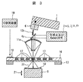
[第2の実施の形態]
次に、本発明に係る分子構造複合同定装置の第2の実施の形態について図3を用いて説明する。第2の実施の形態において、第1の実施の形態と相違する点は、X線光学素子12として、X線被照射面がX線をほぼ全反射可能なように表面状態が調整(制御)され、ほぼ全反射されたX線が0.5mm程度以下の直径に収束するように表面形状が形成されたX線反射鏡12bで構成したことにある。そのため、X線発生部(X線管)1を少し傾けて構成した。このようにX線光学素子12としてX線反射鏡12bで構成しても、X線ビームをX線反射鏡12bにより0.5mm程度以下の直径に絞られて、対物鏡(カセグレーン反射光学系)11aのX線ビーム軸に形成された穴を通して被検試料17に照射することが可能となる。
[Second Embodiment]
Next, a second embodiment of the molecular structure composite identification apparatus according to the present invention will be described with reference to FIG. The second embodiment is different from the first embodiment in that the surface state of the X-ray
[第3の実施の形態]
次に、本発明に係る分子構造複合同定装置の第3の実施の形態について図4を用いて説明する。第3の実施の形態において、第1の実施の形態と相違する点は、集光光学素子11としてX線キャピラリ12aが挿入できる穴明き対物レンズ11bで構成したことにある。このように、集光光学素子11として穴明き対物レンズ11bで構成しても、被検試料17に対して可視光及びラマン光を集光して照射でき、被検試料17からの散乱光及び反射光を集光して試料観察カメラ3で可視光の光学像を取得することが可能となると共に、ラマン光受光装置5でラマン光を受光することが可能となる。穴明き対物レンズ11bは対物鏡よりも製造し易いメリットを有する。
[Third Embodiment]
Next, a third embodiment of the molecular structure composite identification apparatus according to the present invention will be described with reference to FIG. The third embodiment is different from the first embodiment in that the condensing optical element 11 includes a perforated
[第4の実施の形態]
次に、本発明に係る分子構造複合同定装置の第4の実施の形態について図5を用いて説明する。第4の実施の形態において、第1の実施の形態と相違する点は、X線光学素子12としてX線反射鏡12bで構成したことにある。そのため、X線発生部(X線管)1を少し傾けて構成した。第4の実施の形態において、さらに、第2の実施の形態と相違する点は、集光光学素子11としてX線ビームを通す穴明き対物レンズ11bで構成したことにある。このようにX線光学素子12としてX線反射鏡12bで構成しても、X線ビームをX線反射鏡12bにより0.5mm程度以下の直径に絞られて、穴明き対物レンズ11bのX線ビーム軸に形成された穴を通して被検試料17に照射することが可能となる。さらに、集光光学素子11として穴明き対物レンズ11bで構成しても、被検試料17に対して可視光及びラマン光を集光して照射でき、被検試料17からの散乱光及び反射光を集光して試料観察カメラ3で可視光の光学像を取得することが可能となると共に、ラマン光受光装置5でラマン光を受光することが可能となる。穴明き対物レンズ11bは製造し易いメリットを有する。
[Fourth Embodiment]
Next, a fourth embodiment of the molecular structure composite identification apparatus according to the present invention will be described with reference to FIG. The fourth embodiment is different from the first embodiment in that the X-ray
[第5の実施の形態]
次に、本発明に係る分子構造複合同定装置の第5の実施の形態について図8を用いて説明する。第5の実施の形態は、被検試料載置板として各被検試料の溶解性(融点)を測定する手段を備えたものである。図8は、被検試料載置板16’としてガラス(又はプラスチック)サブストレート161と機能性ボトムフィルム162bとで構成される場合を示す側面断面図である。なお、図8においては、ガラス(又はプラスチック)サブストレート161と機能性ボトムフィルム162bとを離した状態で示す。機能性ボトムフィルム162bとしては、ポリイミドフィルム(厚さ12.5〜25μm程度)1621の表面側には各被検試料を個別に加熱できるパターン化された個別加熱用非晶質抵抗膜(例えば非晶質のCr−Si−O系)1623を形成し、その上にガラス(又はプラスチック)が被覆され、ポリイミドフィルム1621の裏側には各被検試料の温度を検出するためのパターン化された温度検出用非晶質半導体膜(例えば非晶質のa−Si系)1622を形成し、その上にガラス(又はプラスチック)が被覆されて形成される。このようにボトムフィルムを機能性ボトムフィルム162bで構成することによって、個別加熱用非晶質抵抗膜1623を個別に温度制御して各被検試料を加熱していって各被検試料の溶解性(融点)を温度検出用非晶質半導体膜1622で個別に検出することが可能となる。個別温度検出用非晶質半導体膜1622および個別加熱用非晶質抵抗膜1623は、配線により被検試料載置板16の端部のコネクタ部(図示せず)まで引き出され、該コネクタ部から全体制御部15及びデータ処理部15aに接続されることになる。このように、被検試料載置板16’を構成することによって、被検試料載置板16’上にセル又はウエルとして載置された各被検試料17について結晶形態を示す可視光の光学像を観察し、多形解析が可能なX線回折スペクトルおよび結合解析が可能な例えばラマン散乱スペクトルを取得した後、各被検試料17を加熱して各被検試料の溶解性(融点)を測定してデータ処理部15aに入力して記憶装置15cに蓄積できることになる。
[Fifth Embodiment]
Next, a fifth embodiment of the molecular structure composite identification apparatus according to the present invention will be described with reference to FIG. The fifth embodiment is provided with means for measuring the solubility (melting point) of each test sample as the test sample mounting plate. FIG. 8 is a side cross-sectional view showing a case where the test
各被検試料の溶融した時点は、例えばラマン散乱光のスペクトルの変化を見ていれば、検出することが可能である。また、測定される温度の変化を見ていれば、各被検試料の溶融した時点を検出することが可能である。従って、各被検試料の溶融した時点における温度(融点)を個別の半導体膜1622によって測定できることになる。
The time at which each test sample is melted can be detected, for example, by looking at the change in the spectrum of the Raman scattered light. Moreover, if the change of the measured temperature is observed, it is possible to detect the time when each test sample is melted. Therefore, the temperature (melting point) at the time when each test sample is melted can be measured by the
なお、各被検試料の溶解性(融点)が測定できれば、ポリイミドフィルム1621の表側にパターン化された個別温度検出用非晶質半導体膜1622を形成し,ポリイミドフィルム1621の裏側にパターン化された個別加熱用非晶質抵抗膜1623を形成しても良い。また、半導体膜1622及び抵抗膜1623を非晶質にしたのは各被検試料17からX線回折スペクトルを検出することができるためである。
If the solubility (melting point) of each test sample can be measured, an
[被検試料載置板の実施例]
次に、本発明に係る分子構造複合同定装置に用いられる被検試料載置板16の実施例について図9を用いて説明する。
[Example of test sample mounting plate]
Next, an embodiment of the test
図9(a)は、16×16ウェル・アレイ・サブストレートの実施例を示す上面図である。また、図9(b)は、RFID(radiofrequency identification)18aを装着したウェル・アレイ・サブストレートを示す斜視図である。このように、RFID18aには、被検試料載置板16に付与された個体識別用符号若しくは情報18、被検査試料載置板上における各被検試料の位置座標若しくは位置情報及び各被検試料の形成条件を記録させることは可能となる。その結果、RFID18aに記録された情報を読み取ることによって、全体制御部15は入力手段15bで入力することなく、取得できることになる。
FIG. 9A is a top view showing an embodiment of a 16 × 16 well array substrate. FIG. 9B is a perspective view showing a well array substrate equipped with an RFID (radiofrequency identification) 18a. As described above, the
また、図9(c)は、被検試料載置板16としてガラス(又はプラスチック)サブストレート161とポリイミドフィルム1621からなるボトムフィルム162aとで構成される場合を示す側面断面図である。なお、図9(c)においては、ガラス(又はプラスチック)サブストレート161とボトムフィルム162aとを離した状態で示す。
FIG. 9C is a side sectional view showing a case where the test
以上説明したように、本発明に係る分子構造複合同定装置の実施の形態によれば、多数の被検試料に対してX線回折と赤外光・可視光・紫外光・ラマン散乱の何れか一つあるいは複数とを同時又は連続的に行って間違いが生じることなく正確に且つ効率良く短時間で分子構造(結晶形態、多形解析、結合解析等)について複合同定を行うことができる。さらに図2に破壊試験2で示すように、各被検試料の溶解性についても同定することが可能となる。
As described above, according to the embodiment of the molecular structure composite identification apparatus of the present invention, any one of X-ray diffraction and infrared light / visible light / ultraviolet light / Raman scattering is applied to a large number of test samples. Complex identification can be performed on molecular structures (crystal morphology, polymorphism analysis, binding analysis, etc.) accurately and efficiently in a short time without making errors by performing one or more simultaneously or sequentially. Further, as shown in the
また、本発明の実施の形態によれば、可視光による被検試料の光学像の取得と同一部位のラマン散乱スペクトル、反射赤外線スペクトル、反射紫外線スペクトル及びX線回折パターンが同時あるいは時間間隔をあけることなく取得することが可能となる。物質中の分子構造の非破壊測定及び同定は、結合解析(官能基の存在や短距離秩序構造である基本構造)については、ラマン散乱・赤外線・紫外線スペクトルによる測定解析が優れ、結晶化した被検試料の多形解析(結晶構造や長距離の秩序構造)についてはX線回折による測定解析が優れている。 Further, according to the embodiment of the present invention, the Raman scattering spectrum, the reflected infrared spectrum, the reflected ultraviolet spectrum, and the X-ray diffraction pattern at the same site as the acquisition of the optical image of the test sample by visible light are simultaneously or spaced apart. It becomes possible to acquire without. For nondestructive measurement and identification of molecular structure in materials, bond analysis (the existence of functional groups and basic structures that are short-range ordered structures) is excellent in measurement analysis by Raman scattering, infrared and ultraviolet spectra, Measurement analysis by X-ray diffraction is excellent for polymorphic analysis (crystal structure and long-range ordered structure) of the specimen.
従って、本発明に係る複合分子構造同定装置を用いることにより、光学像で捉えた被検試料の結晶形態や官能基の有無といった分子構造が容易に測定解析し、同定することが可能となる。また、作成条件を多岐にわたって変更した被検試料についても迅速に光学像と分子構造の同定が可能であり、これらの被検試料の作成条件、測定条件、光学像、測定スペクトルや回折パターンと、解析・同定結果を順次自動的にコンピュータの記録装置に蓄積することが可能となる。 Therefore, by using the complex molecular structure identification apparatus according to the present invention, it is possible to easily measure and analyze the molecular structure such as the crystal form of the test sample captured by an optical image and the presence or absence of a functional group, and identify the molecular structure. In addition, it is possible to quickly identify the optical image and molecular structure of the test sample with various preparation conditions, and the preparation conditions, measurement conditions, optical image, measurement spectrum and diffraction pattern of these test samples, Analysis / identification results can be automatically and sequentially stored in a computer recording device.
蓄積されたデータを、被検試料の作成条件と測定・解析。同定結果とにより整理することにより、コンピュータ画面上で、容易に目的とする被検試料の分子構造状態の作成条件を表示することが可能であり、作成条件探索の自動化・短時間化が可能となる。また、作成の条件や被検試料の取り扱いについても試料搭載プレート(被検試料載置板)に取り付けた識別用の情報を読み取ることにより人為的な誤りを極小にした高信頼システムを形成している。従って、これらの作成条件については、何時でも再現できるシステムであり、トレーサブルな材料形成システムを構成することが可能である。 The accumulated data is used to create the test sample and measure / analyze it. By organizing according to the identification results, it is possible to easily display the creation conditions of the molecular structure state of the target sample on the computer screen, making it possible to automate and shorten the creation condition search. Become. In addition, with regard to the preparation conditions and the handling of the test sample, a highly reliable system that minimizes human error is formed by reading the identification information attached to the sample mounting plate (test sample mounting plate). Yes. Therefore, these production conditions can be reproduced at any time, and a traceable material forming system can be configured.
1…X線発生部(X線管)、2…試料照明光源(可視光又はラマン(赤外線・紫外線)光照明光源)、3…試料観察カメラ(受光装置)、4…マウント部、4a…全反射ミラー、4b…ハーフミラー、4c…ハーフミラー、5…ラマン(赤外線・紫外線)光受光装置、6…X線遮断装置(X線シャッター装置)、7…ラマン(赤外線・紫外線)光分光装置、8…X線発生部用電源装置、9、53…X線検出器(X線シンチレーションカウンタ)、9b、52…スリット、10…リングシャッタ、11…集光光学素子、11a…対物鏡(カセグレーン反射光学系)、11b…対物レンズ、12…X線光学素子、12a…X線キャピラリ、12b…X線反射鏡、13…試料保持機構(試料搭載台)、14…移動装置(ステージ)、15…全体制御部、15a…データ処理部、15b…表示装置、15c…記憶装置、16、16’…被検試料載置板(被検試料セル又はウエル付き試料プレート)、17…被検試料、18…個体識別用符号若しくは情報(例えばID番号)、18a…RFID、19…読み取り装置、20…X線回折、21…直線移動型位置調整機構、22…ラマン励起用レーザー光源(ラマン光照明光源)、23…光ファイバー、30…分子構造複合同定装置、31…統合非破壊検査、51…X線通過部、161…ガラス(又はプラスチック)サブストレート、162a…ボトムフィルム、162b…機能性ボトムフィルム、1621…ポリイミドフィルム、1622…個別温度検出用非晶質半導体膜、1623…個別加熱用非晶質抵抗体膜。
DESCRIPTION OF
Claims (15)
X線ビームを発生するX線発生部と、
該X線発生部から発生したX線ビームの照射・非照射を制御するシャッター装置と、
該シャッター装置を通して照射されたX線ビームを0.5mm以下の直径に制限して前記ビーム軸上に位置する前記被検試料に対して照射するX線光学素子と、
ラマン光の波長ビームを出射する照明光源と、
該照明光源から出射された前記波長ビームを前記ビーム軸上に位置する前記被検試料に対して集光して照射し、該被検試料から放出されるラマン散乱光を集光する集光光学系と、
前記被検試料を挟んで前記X線光学素子と相対峙して設置され、前記X線ビームが照射された被検試料からのX線回折パターンを検出するX線検出器と、
前記集光光学系で集光されたラマン散乱光を受光して検出する受光装置を含む検出光学系とを備え、
前記集光光学系において前記X線光学素子を配置する穴又は前記X線光学素子から照射されるX線ビームを通過させる穴を前記ビーム軸上に設けることによって、前記ビーム軸上に位置する前記被検試料に対して前記X線光学素子によるX線ビームの照射と前記集光光学系による波長ビームの集光照射とを同時若しくは連続して行い、前記X線検出器で検出されるX線回折パターンのデータと前記検出光学系で検出されるラマン散乱スペクトルのデータとを前記ビーム軸上に位置する前記被検試料から同時若しくは連続して取得することを特徴とする分子構造複合同定装置。 A moving device that moves a sample holding mechanism for holding a test sample mounting plate to sequentially position each of a plurality of test samples mounted as cells or wells on the test sample mounting plate on a beam axis; ,
An X-ray generator for generating an X-ray beam;
A shutter device for controlling irradiation / non-irradiation of the X-ray beam generated from the X-ray generation unit;
An X-ray optical element that irradiates the test sample positioned on the beam axis by limiting the X-ray beam irradiated through the shutter device to a diameter of 0.5 mm or less;
An illumination light source that emits a wavelength beam of Raman light;
Condensing optics for condensing and irradiating the test sample located on the beam axis with the wavelength beam emitted from the illumination light source, and condensing the Raman scattered light emitted from the test sample The system,
An X-ray detector that is installed relative to the X-ray optical element across the test sample and detects an X-ray diffraction pattern from the test sample irradiated with the X-ray beam;
A detection optical system including a light receiving device that receives and detects Raman scattered light collected by the light collecting optical system;
In the condensing optical system , a hole for arranging the X-ray optical element or a hole for allowing the X-ray beam irradiated from the X-ray optical element to pass through is provided on the beam axis, whereby the position located on the beam axis is set. X-rays detected by the X-ray detector by performing X-ray beam irradiation by the X-ray optical element and wavelength beam condensing irradiation by the condensing optical system simultaneously or successively on the test sample A molecular structure composite identification apparatus characterized in that diffraction pattern data and Raman scattering spectrum data detected by the detection optical system are acquired simultaneously or successively from the test sample located on the beam axis.
更に、前記被検試料載置板は、ポリイミドフィルムの表面側に形成されたパターン化された個別加熱用非晶質抵抗膜と前記ポリイミドフィルムの裏側に形成されたパターン化された個別温度検出用非晶質半導体膜とで構成された機能性ボトムフィルム上にガラス又はプラスチックサブストレートを設けて構成し、該ガラス又はプラスチックサブストレート上にセル又はウエルとして載置された各被検試料を前記個別加熱用非晶質抵抗膜により個別に加熱して前記個別温度検出用非晶質半導体膜により各被検試料の温度を測定して各被検試料の溶解性を個別に測定する手段を備え、該手段によって各被検試料の溶解性のデータを取得することを特徴とする分子構造複合同定装置。 In the molecular structure composite identification apparatus according to claim 1,
Further, the test sample mounting plate includes a patterned individual heating amorphous resistance film formed on the surface side of the polyimide film and a patterned individual temperature detection formed on the back side of the polyimide film. A glass or plastic substrate is provided on a functional bottom film composed of an amorphous semiconductor film, and each test sample placed as a cell or well on the glass or plastic substrate is individually A means for individually measuring the solubility of each test sample by individually heating by the amorphous resistance film for heating and measuring the temperature of each test sample by the amorphous semiconductor film for individual temperature detection; A molecular structure composite identification apparatus characterized in that solubility data of each test sample is acquired by the means.
前記移動装置は、前記被検試料載置板上にセル又はウエルとして載置された被検試料の位置座標が前記ビーム軸に対して連続的或いは離散的に制御されるように構成したことを特徴とする分子構造複合同定装置。 In the molecular structure composite identification apparatus according to claim 1,
The moving device is configured such that the position coordinates of a test sample placed as a cell or well on the test sample mounting plate are controlled continuously or discretely with respect to the beam axis. Characteristic molecular structure composite identification device.
前記X線光学素子を、内径が0.5mm以下の管状の反射X線キャピラリで構成したことを特徴とする分子構造複合同定装置。 In the molecular structure composite identification apparatus according to claim 1,
A molecular structure composite identification apparatus, wherein the X-ray optical element comprises a tubular reflective X-ray capillary having an inner diameter of 0.5 mm or less.
前記X線光学素子を、反射されたX線が前記被検試料に収束するように表面形状を形成したX線反射鏡で構成したことを特徴とする分子構造複合同定装置。 In the molecular structure composite identification apparatus according to claim 1,
A molecular structure composite identification apparatus, wherein the X-ray optical element is composed of an X-ray reflecting mirror having a surface shape so that reflected X-rays converge on the test sample.
前記集光光学系を、前記X線光学素子から照射されるX線ビームを通過させる穴を前記ビーム軸上に設けた反射鏡で構成したことを特徴とする分子構造複合同定装置。 In the molecular structure composite identification apparatus according to claim 1,
The molecular structure composite identification apparatus, wherein the condensing optical system is constituted by a reflecting mirror provided on the beam axis with a hole through which an X-ray beam irradiated from the X-ray optical element passes.
前記集光光学系を、前記X線光学素子から照射されるX線ビームを通過させる穴を前記ビーム軸上に設けた光学レンズで構成したことを特徴とする分子構造複合同定装置。 In the molecular structure composite identification apparatus according to claim 1,
The molecular structure composite identification apparatus, wherein the condensing optical system is composed of an optical lens provided on the beam axis with a hole through which the X-ray beam irradiated from the X-ray optical element passes.
前記X線検出器を、直径20mm以上80mm以下の検出可能領域を持つX線検出デバイスと、該X線検出デバイスの試料側に被検試料を照射するX線ビームの延長線上の位置を中心として設置された円形スリットと、特定の回折線のみを前記X線検出デバイスに照射するように透過させるための直線移動型位置調整機構とを備えて構成したことを特徴とする分子構造複合同定装置。 In the molecular structure composite identification apparatus according to claim 1,
The X-ray detector is centered on an X-ray detection device having a detectable region with a diameter of 20 mm or more and 80 mm or less, and a position on the extended line of the X-ray beam that irradiates the sample to the sample side of the X-ray detection device. A molecular structure composite identification apparatus comprising: an installed circular slit; and a linear movement type position adjusting mechanism for transmitting only a specific diffraction line so as to irradiate the X-ray detection device.
前記X線検出器として2次元のX線検出器を用い、被検試料を照射するX線ビームの延長線上の位置を中心とする円環状領域毎に積算した数値を求めることにより被検試料のX線回折パターンのデータを取得することを特徴とする分子構造複合同定装置。 In the molecular structure composite identification apparatus according to claim 1,
A two-dimensional X-ray detector is used as the X-ray detector, and a numerical value integrated for each annular region centering on a position on an extended line of the X-ray beam irradiating the test sample is obtained. A molecular structure composite identification apparatus characterized by acquiring X-ray diffraction pattern data.
前記被検試料載置板には少なくとも個体識別用符号若しくは情報を付与して構成し、
該付与された個体識別用符号若しくは情報を機械的・光学・電磁波・磁気の何れかあるいは複数の方法によって読み取る読み取り装置を備えたことを特徴とする分子構造複合同定装置。 In the molecular structure composite identification apparatus according to claim 1,
The test sample mounting plate is configured with at least an individual identification code or information,
A molecular structure composite identification apparatus comprising a reader for reading the assigned individual identification code or information by any one of mechanical, optical, electromagnetic, and magnetic methods or a plurality of methods.
更に、前記被検試料載置板に付与された個体識別用符号若しくは情報と、前記被検査試料載置板上にセル又はウエルとして載置された各被検試料の位置座標若しくは位置情報とを、前記各被検試料から取得されるデータに対応させて管理する管理手段を備えたことを特徴とする分子構造複合同定装置。 In the molecular structure composite identification apparatus according to claim 1,
Furthermore, the individual identification code or information given to the test sample mounting plate, and the position coordinates or position information of each test sample mounted as a cell or well on the test sample mounting plate A molecular structure composite identification apparatus comprising management means for managing data corresponding to data acquired from each test sample.
更に、前記被検試料載置板上にセル又はウエルとして載置された各被検試料の識別情報を、前記各被検試料から取得されるデータに対応させて記憶する記憶装置を備えたことを特徴とする分子構造複合同定装置。 In the molecular structure composite identification apparatus according to claim 1,
And a storage device for storing the identification information of each test sample placed as a cell or well on the test sample mounting plate in correspondence with the data acquired from each test sample. Molecular structure composite identification device characterized by
更に、前記被検試料載置板上にセル又はウエルとして載置された各被検試料の識別情報及び該各被検試料の形成条件を、前記各被検試料から取得されるデータに対応させて記憶する記憶装置を備えたことを特徴とする分子構造複合同定装置。 In the molecular structure composite identification apparatus according to claim 1,
Further, the identification information of each test sample placed as a cell or well on the test sample mounting plate and the formation conditions of each test sample are made to correspond to the data acquired from each test sample. A molecular structure composite identification device comprising a storage device for storing information.
複数枚の被検試料載置板を保管する保管用試料ホルダーと、該保管用試料ホルダーと前記試料保持機構との間で前記被検試料載置板を自動的に交換する交換装置とを備え、一枚の被検試料載置板に対する測定が終了する毎に、保管用試料ホルダー中の被検試料載置板を前記交換装置により前記試料保持機構へと順次あるいは指定された順序で交換することを特徴とする分子構造複合同定装置。 In the molecular structure composite identification apparatus according to claim 1,
A storage sample holder for storing a plurality of test sample mounting plates; and an exchange device for automatically replacing the test sample mounting plate between the storage sample holder and the sample holding mechanism. Each time the measurement on a single test sample mounting plate is completed, the test sample mounting plate in the storage sample holder is replaced with the sample holding mechanism sequentially or in a designated order by the replacement device. Molecular structure composite identification apparatus characterized by the above.
更に、前記被検試料載置板上にセル又はウエルとして載置された各被検試料の識別情報及び該各被検試料の形成条件を、前記各被検試料から取得されるデータに対応させて記憶する記憶装置を備えたことを特徴とする分子構造複合同定装置。 In the molecular structure composite identification apparatus according to claim 14,
Further, the identification information of each test sample placed as a cell or well on the test sample mounting plate and the formation conditions of each test sample are made to correspond to the data acquired from each test sample. A molecular structure composite identification device comprising a storage device for storing information.
Priority Applications (1)
| Application Number | Priority Date | Filing Date | Title |
|---|---|---|---|
| JP2005032530A JP4101812B2 (en) | 2005-02-09 | 2005-02-09 | Molecular structure compound identification system |
Applications Claiming Priority (1)
| Application Number | Priority Date | Filing Date | Title |
|---|---|---|---|
| JP2005032530A JP4101812B2 (en) | 2005-02-09 | 2005-02-09 | Molecular structure compound identification system |
Publications (2)
| Publication Number | Publication Date |
|---|---|
| JP2006220467A JP2006220467A (en) | 2006-08-24 |
| JP4101812B2 true JP4101812B2 (en) | 2008-06-18 |
Family
ID=36982897
Family Applications (1)
| Application Number | Title | Priority Date | Filing Date |
|---|---|---|---|
| JP2005032530A Expired - Fee Related JP4101812B2 (en) | 2005-02-09 | 2005-02-09 | Molecular structure compound identification system |
Country Status (1)
| Country | Link |
|---|---|
| JP (1) | JP4101812B2 (en) |
Families Citing this family (9)
| Publication number | Priority date | Publication date | Assignee | Title |
|---|---|---|---|---|
| JP4674910B2 (en) * | 2007-03-29 | 2011-04-20 | セキテクノトロン株式会社 | Crystal polymorph automatic determination method and apparatus by Raman spectroscopy |
| WO2010024397A1 (en) * | 2008-08-28 | 2010-03-04 | 独立行政法人理化学研究所 | Raman scattering measurement device |
| US8106360B2 (en) * | 2009-06-22 | 2012-01-31 | Uchicago Argonne, Llc | Microscopic infrared analysis by X-ray or electron radiation |
| JP5589555B2 (en) * | 2010-05-20 | 2014-09-17 | 日亜化学工業株式会社 | X-ray analyzer |
| JP5704630B2 (en) * | 2010-06-24 | 2015-04-22 | 日本電信電話株式会社 | Crystallization process control method and apparatus |
| JP5707213B2 (en) * | 2011-04-20 | 2015-04-22 | ブルカー・オプティクス株式会社 | Infrared transmission spectrum measuring device |
| EP2824445B1 (en) * | 2013-07-08 | 2016-03-02 | Fei Company | Charged-particle microscopy combined with raman spectroscopy |
| JP2018115921A (en) * | 2017-01-17 | 2018-07-26 | 東芝Itコントロールシステム株式会社 | X-ray inspection device |
| JP2021081277A (en) * | 2019-11-18 | 2021-05-27 | パルステック工業株式会社 | X-ray diffraction measurement device |
-
2005
- 2005-02-09 JP JP2005032530A patent/JP4101812B2/en not_active Expired - Fee Related
Also Published As
| Publication number | Publication date |
|---|---|
| JP2006220467A (en) | 2006-08-24 |
Similar Documents
| Publication | Publication Date | Title |
|---|---|---|
| JP4101812B2 (en) | Molecular structure compound identification system | |
| US6707548B2 (en) | Systems and methods for filter based spectrographic analysis | |
| AU2001246447B2 (en) | Spr sensor system | |
| WO2002057763A2 (en) | Apparatus and method for identification of crystals by in-situ x-ray diffraction | |
| US20060023837A1 (en) | Combinatorial screening system with X-ray diffraction and Raman spectroscopy | |
| JP2005164615A (en) | Processing method and device for optical examination | |
| JP2006208294A (en) | Device and method for concurrently imaging plasmon resonance and fluorescence | |
| US20060124443A1 (en) | Control and monitoring of non-resonant radiation-induced nucleation, crystallization, and polymorph formation | |
| JP2010525334A (en) | Methods of using biosensors to detect small molecules that bind directly to an immobilized target | |
| JP5713357B2 (en) | X-ray stress measurement method and apparatus | |
| WO2001082659A1 (en) | System and methods for the high throughput screening of polymorphs | |
| JP2009002805A (en) | Small angle/wide angle x-ray measuring device | |
| JP2006284210A (en) | X-ray monocrystal evaluator | |
| JP4674910B2 (en) | Crystal polymorph automatic determination method and apparatus by Raman spectroscopy | |
| JP2007178442A6 (en) | Imaging apparatus and method | |
| CN110274895A (en) | The discrete fluorescence spectrum of multi-detector and fluorescence lifetime detection method and device | |
| Klink et al. | A newly designed microspectrofluorometer for kinetic studies on protein crystals in combination with x-ray diffraction | |
| CN101454650A (en) | Lens system | |
| IL162965A (en) | Apparatus and method for imaging | |
| JP2006250642A (en) | X-ray diffraction analyzing method and x-ray diffraction analyzer | |
| JP3736361B2 (en) | Foreign matter identification method, foreign matter identification device, and dust generation source identification method | |
| JP2002529699A (en) | X-ray diffractometer with x-ray optical reference channel | |
| JP7057349B2 (en) | Methods and equipment for detecting process parameters in liquid media | |
| JP6717201B2 (en) | Detection method and detection device | |
| JP2006300808A (en) | Raman spectrometry system |
Legal Events
| Date | Code | Title | Description |
|---|---|---|---|
| A977 | Report on retrieval |
Free format text: JAPANESE INTERMEDIATE CODE: A971007 Effective date: 20070824 |
|
| A131 | Notification of reasons for refusal |
Free format text: JAPANESE INTERMEDIATE CODE: A131 Effective date: 20070904 |
|
| A521 | Written amendment |
Free format text: JAPANESE INTERMEDIATE CODE: A523 Effective date: 20071105 |
|
| RD02 | Notification of acceptance of power of attorney |
Free format text: JAPANESE INTERMEDIATE CODE: A7422 Effective date: 20071105 |
|
| A131 | Notification of reasons for refusal |
Free format text: JAPANESE INTERMEDIATE CODE: A131 Effective date: 20071204 |
|
| A521 | Written amendment |
Free format text: JAPANESE INTERMEDIATE CODE: A523 Effective date: 20080130 |
|
| TRDD | Decision of grant or rejection written | ||
| A01 | Written decision to grant a patent or to grant a registration (utility model) |
Free format text: JAPANESE INTERMEDIATE CODE: A01 Effective date: 20080226 |
|
| A61 | First payment of annual fees (during grant procedure) |
Free format text: JAPANESE INTERMEDIATE CODE: A61 Effective date: 20080319 |
|
| FPAY | Renewal fee payment (event date is renewal date of database) |
Free format text: PAYMENT UNTIL: 20110328 Year of fee payment: 3 |
|
| R150 | Certificate of patent or registration of utility model |
Ref document number: 4101812 Country of ref document: JP Free format text: JAPANESE INTERMEDIATE CODE: R150 Free format text: JAPANESE INTERMEDIATE CODE: R150 |
|
| FPAY | Renewal fee payment (event date is renewal date of database) |
Free format text: PAYMENT UNTIL: 20110328 Year of fee payment: 3 |
|
| FPAY | Renewal fee payment (event date is renewal date of database) |
Free format text: PAYMENT UNTIL: 20120328 Year of fee payment: 4 |
|
| FPAY | Renewal fee payment (event date is renewal date of database) |
Free format text: PAYMENT UNTIL: 20130328 Year of fee payment: 5 |
|
| FPAY | Renewal fee payment (event date is renewal date of database) |
Free format text: PAYMENT UNTIL: 20130328 Year of fee payment: 5 |
|
| FPAY | Renewal fee payment (event date is renewal date of database) |
Free format text: PAYMENT UNTIL: 20140328 Year of fee payment: 6 |
|
| R250 | Receipt of annual fees |
Free format text: JAPANESE INTERMEDIATE CODE: R250 |
|
| R250 | Receipt of annual fees |
Free format text: JAPANESE INTERMEDIATE CODE: R250 |
|
| R250 | Receipt of annual fees |
Free format text: JAPANESE INTERMEDIATE CODE: R250 |
|
| R250 | Receipt of annual fees |
Free format text: JAPANESE INTERMEDIATE CODE: R250 |
|
| R250 | Receipt of annual fees |
Free format text: JAPANESE INTERMEDIATE CODE: R250 |
|
| LAPS | Cancellation because of no payment of annual fees |