WO2010024397A1 - Raman scattering measurement device - Google Patents
Raman scattering measurement device Download PDFInfo
- Publication number
- WO2010024397A1 WO2010024397A1 PCT/JP2009/065090 JP2009065090W WO2010024397A1 WO 2010024397 A1 WO2010024397 A1 WO 2010024397A1 JP 2009065090 W JP2009065090 W JP 2009065090W WO 2010024397 A1 WO2010024397 A1 WO 2010024397A1
- Authority
- WO
- WIPO (PCT)
- Prior art keywords
- light
- raman
- filter
- wavelength
- measurement
- Prior art date
Links
Images


Classifications
-
- G—PHYSICS
- G01—MEASURING; TESTING
- G01N—INVESTIGATING OR ANALYSING MATERIALS BY DETERMINING THEIR CHEMICAL OR PHYSICAL PROPERTIES
- G01N21/00—Investigating or analysing materials by the use of optical means, i.e. using sub-millimetre waves, infrared, visible or ultraviolet light
- G01N21/62—Systems in which the material investigated is excited whereby it emits light or causes a change in wavelength of the incident light
- G01N21/63—Systems in which the material investigated is excited whereby it emits light or causes a change in wavelength of the incident light optically excited
- G01N21/65—Raman scattering
- G01N2021/653—Coherent methods [CARS]
- G01N2021/656—Raman microprobe
Definitions
- the present invention relates to a Raman scattering measurement device, and more particularly to a Raman scattering measurement device capable of measuring Raman scattering under white light illumination.
- Raman scattering is a phenomenon in which when a material is irradiated with light, the scattered light includes light having a wavelength different from the wavelength of the incident light.
- the difference (Raman shift) between the frequency of Raman scattered light and incident light corresponds to the frequency of the natural vibration mode of the molecule and takes a value specific to the structure of the substance. Therefore, the substance can be identified from the Raman spectrum obtained by irradiating the substance with laser light, which is monochromatic light, and detecting the generated Raman scattered light with the spectroscope.
- the intensity of Raman scattered light is very weak and is only about 1 / 100,000 to 100 million of the excitation light.
- the observation light white light
- it is necessary to turn off the observation light for example, Patent Document 1.
- Patent Document 2 there is known a micro-Raman apparatus that enables Raman measurement while observing with an optical microscope by using laser light having a wavelength different from the wavelength of the excitation laser as observation light.
- Non-patent Document 1 an endoscope for Raman measurement of tissue in a living body
- Raman measurement is performed by inserting a Raman probe (Patent Documents 3 and 4) into a channel of an endoscope.
- a Raman measurement By performing a Raman measurement on the living tissue, for example, it is possible to diagnose whether the affected area is cancer.
- the Raman measurement using the endoscope it is necessary to perform the Raman measurement with the illumination for observation (white light) turned off.
- JP 2007-292704 A Japanese Patent Laid-Open No. 10-90064 Japanese Patent No. 4041421 JP 2004-294099 A
- the measurement site can be observed with a monochromatic light laser having a wavelength different from the wavelength of the excitation laser, color information cannot be obtained because it is monochromatic light. There is also a problem that monochromatic light makes it very difficult to see an image due to speckles. In particular, since color information is very important in the observation of living tissue, observation with white light is desired.
- the present invention has been made in consideration of such problems, and an object thereof is to provide a technique capable of performing Raman measurement while observing a measurement site with white light.
- the Raman scattering measurement apparatus is A white light source that emits white light for observation to irradiate the measurement site; A laser light source that emits an excitation laser for irradiating the measurement site; A spectroscope for measuring Raman scattered light generated from the measurement site; Have The white light source is provided with an interference light removal filter that removes light near the wavelength of the excitation laser, The light receiving portion of the spectroscope is provided with a high-order diffracted light removing filter that removes light having a wavelength corresponding to the high-order diffracted light of the spectroscope.
- the excitation laser is preferably near infrared light.
- near-infrared light not only can interference of fluorescence be avoided, but even if light in this frequency region is removed from white light for observation, the whiteness of the light is not significantly impaired.
- Both the interference light removal filter and the high-order diffracted light removal filter in the present invention are preferably interference filters.
- the interference filter is a filter that transmits or reflects light in a predetermined wavelength region by using the light interference action of the thin film or its multilayer film. In Raman measurement, it is necessary to block interference light with high accuracy (optical density of 6 to 8 or more), so it is preferable to use an interference filter.
- the interference light removal filter provided on the white light source side may be a band cut filter that can remove light in the vicinity of the wavelength of the excitation laser, but a long cut filter (short pass filter) that removes wavelengths greater than the wavelength of the excitation laser. ).
- the high-order diffracted light removal filter provided in the light receiving section of the spectroscope may be a band cut filter that removes only the high-order diffracted light, but a long-pass filter (shortcut filter) that transmits only light having a wavelength longer than the wavelength of the second-order diffracted light. ).
- the high-order diffracted light removing filter does not need to remove all the high-order diffracted light components, and only removes the high-order diffracted light detected by the spectrometer as the high-order diffracted light. For example, if third-order or higher-order diffracted light is not detected by the spectroscope, the high-order diffracted light removal filter only needs to remove the second-order diffracted light.
- the present invention can also be understood as a Raman scattering measurement device that performs Raman measurement inside a living body in combination with an endoscope. That is, the present invention A laser light source emitting an excitation laser; A spectroscope for measuring Raman scattered light; A Raman probe having an excitation-side light guide for guiding light from the laser light source to a measurement site, and a light-receiving side light guide for guiding signal light from the measurement site to the spectrometer; An endoscope having a light source that emits white light for observation for irradiating the measurement site, and an endoscope into which the Raman probe can be inserted, A Raman scattering measuring device for measuring Raman scattering of in vivo tissue composed of: The white light source is provided with an interference light removal filter that removes light near the wavelength of the excitation laser, The light receiving portion of the spectroscope is provided with a high-order diffracted light removal filter that removes light having a wavelength corresponding to the high-order diffracted light
- the Raman scattering measurement apparatus According to the Raman scattering measurement apparatus according to the present invention, it is possible to perform Raman measurement while observing the measurement site with white light.
- FIG. 1 is a diagram illustrating a configuration of an endoscope system using the Raman scattering measurement apparatus according to the first embodiment.
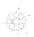
- FIG. 2 is a diagram showing an end portion on the excitation light emission side of the Raman probe.
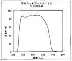
- FIG. 3 is a diagram showing the filter characteristics of (A) a Raman edge filter and (B) a short wavelength cut filter.
- FIG. 4 is a diagram illustrating filter characteristics of the infrared cut filter.
- 5A and 5B are diagrams showing the influence of observation light in a conventional apparatus, FIG. 5A is a diagram showing a measurement signal without observation light, and FIG. 5B is a diagram showing a measurement signal with observation light. .
- FIG. 6 is a diagram for explaining the effect when an infrared cut filter is provided in a white light source
- FIG. 6A is a measurement signal obtained when measurement is performed with observation light without providing an infrared cut filter.
- FIG. 6B is a diagram illustrating a measurement signal when measurement is performed with observation light provided with an infrared cut filter.
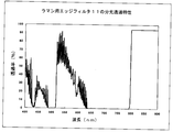
- FIG. 7 is a diagram showing the filter characteristics of the Raman edge filter in a wider wavelength region than that in FIG.
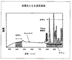
- FIG. 8 is a diagram illustrating a wavelength range that interferes with Raman measurement among the wavelength components included in the observation light.
- FIG. 9 is a diagram illustrating a measurement result when the Raman scattering measurement apparatus according to the first embodiment is used and measurement is performed with observation light and without a sample.
- FIG. 9 is a diagram illustrating a measurement result when the Raman scattering measurement apparatus according to the first embodiment is used and measurement is performed with observation light and without a sample.
- FIG. 10 is a diagram showing a result of measuring the Raman shift of calcium carbonate using the Raman scattering measurement apparatus according to the first embodiment, and compares the case of no observation light (A) and the case of observation light (B). It is a figure to do.
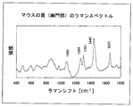
- FIG. 11 is a diagram showing a result of measuring a Raman shift of the pyloric part of a rat while irradiating observation light using the Raman measuring apparatus according to the first embodiment.
- FIG. 12 is a diagram showing a configuration when a white LED light source is used as a light source for observation illumination.
- FIG. 13 is a diagram illustrating a configuration of a micro Raman apparatus according to the second embodiment.
- FIG. 1 is a diagram illustrating a configuration of a Raman scattering measurement apparatus according to the present embodiment.
- a Raman probe and an endoscope are combined to perform Raman measurement inside the living body.
- the Raman scattering measurement apparatus according to this embodiment is characterized in that Raman measurement can be performed while irradiating a measurement site with a white light source and performing observation.
- This Raman scattering measurement apparatus includes an excitation laser light source 1, a Raman spectrometer 2, and a Raman probe 3 that connects a measured object to the excitation laser light source 1 and the Raman spectrometer 2.
- a CW Raman spectroscopy semiconductor laser (EnWave Optronics, ESL-785-400MSF type) having a wavelength of 785 nm was used as the excitation laser light source 1.
- ESL-785-400MSF type CW Raman spectroscopy semiconductor laser
- fluorescence that interferes with Raman scattering may be generated. Therefore, it is necessary to use near infrared rays that are less likely to generate fluorescence.
- a Raman spectrometer (Kaiser Optical Systems, HoloSpec F / 1.8) 2 includes a pre-filter 2a, a transmission diffraction grating 2b, and a CCD detector 2c provided in the light receiving unit.
- the prefilter 2a will be described later.
- the width of the entrance slit as 110 [mu] m (corresponding to the spectral resolution of 5 cm -1), CCD detector 2c so as to measure the 50cm -1 -2000cm -1 wave number range of Raman shift (Andor Technology Co., DU401A-BR- DD) is arranged.
- the signal detected by the CCD detector 2c is sent to the computer 4 for analysis, display, recording, and the like.
- FIG. 2 is a view of the Raman probe 3 as viewed from the excitation light exit end.
- one excitation-side optical fiber 31 located at the center and eight light-receiving-side optical fibers 32 arranged so as to surround it are provided.
- a band-pass filter 33 that allows only the excitation light emitted from the laser light source 1 to pass is attached to the tip of the excitation-side optical fiber 31, and the excitation wavelength does not pass through the tip of the light-receiving-side optical fiber 32, and Raman scattering generated from the sample.
- An edge filter (long wavelength transmission filter) 34 that allows light to pass through is mounted.
- a stainless steel pipe 35 is attached to the tip of the excitation-side optical fiber 31 to shield between the excitation-side optical fiber 31 and the light-receiving side optical fiber 32 so that the excitation light emitted from the excitation-side optical fiber 31 does not enter the light-receiving side optical fiber 32 directly.
- the endoscope 8 is provided with a light guide that guides light from a xenon lamp light source 5 that is a white light source to a measurement site, an image guide that guides observation light to the camera 6, and a working channel that passes the Raman probe 3.
- the state of the measurement site photographed by the camera 6 is displayed on the monitor 7.
- the pre-filter 2a provided on the light receiving unit side of the Raman spectrometer 2 includes a Raman edge filter (long pass filter) 11 and a short wavelength cut filter 12, as shown in the enlarged view of FIG.
- the Raman edge filter 11 is for preventing strong Rayleigh scattered light from entering the spectrometer. As shown in FIG. 3A, the filter characteristics of the edge filter 11 are such that the wavelength of excitation light of 785 nm is cut and Raman scattered light is transmitted. Note that the Raman scattered light is very weak and is about 1 / 1,000,000 or less of the excitation light, so it is necessary to use the edge filter 11 that can sufficiently block the Rayleigh scattered light.
- the short wavelength cut filter 12 is used to block light having a wavelength range of 390 nm to 460 nm which is the second order diffracted light of the Raman spectrometer 2.
- a short wavelength cut filter for blocking light with a wavelength of 460 nm or less is mounted.
- the infrared cut filter 13 used in the xenon lamp light source 5 is a filter that blocks light having a wavelength of 785 nm or more, which is the wavelength of the excitation laser, from the observation light. When light in this wavelength range is irradiated onto the measurement object, it becomes interference light for Raman measurement, and therefore it is necessary to remove the wavelength component.
- a band cut filter that removes only a wavelength around 785 nm may be employed, but light having a wavelength of 785 nm or more is unnecessary for observation, and as shown in FIG.
- a long cut filter short pass filter that removes a wavelength of 700 nm or more is employed.
- the Raman edge filter 11 has been conventionally used.
- the feature of this embodiment is that the wavelength cut filter 12 is employed.
- the disturbing light for Raman measurement is light in the vicinity of the wavelength of the excitation laser. Therefore, if light in this wavelength range is removed from the light emitted from the xenon lamp light source 5, the observation light is considered to be able to perform correct measurement without adversely affecting the Raman measurement. Therefore, a configuration in which the infrared cut filter 13 is applied to a conventional apparatus (that is, a configuration in which the short wavelength cut filter 12 is excluded from the configuration of the present embodiment) was tried.
- FIG. 6 shows the results of measurement without placing a sample.
- FIG. 6 (A) shows the results of measurement by a conventional device
- FIG. 6 (B) shows the results of measurement by a device in which an infrared cut filter is applied to the conventional device. Results are shown. Since no sample is placed, there should be no peaks in the measurement signal without the influence of noise.
- FIG. 6A shows the measurement result when the infrared cut filter 13 is not applied, the influence of light contained in the xenon lamp appears.
- FIG. 6B to which the infrared cut filter 13 is applied, it was expected that no peak appears in the measurement signal by eliminating the influence of the observation light, but the noise could be removed by a shift amount of 1000 cm ⁇ 1 or less. Thus, it was found that noise could not be removed within a shift amount of 1000 cm ⁇ 1 or more.
- the signal observed in FIG. 6B is light having a wavelength range of 390 nm to 460 nm corresponding to the second-order diffracted light of the spectrometer 2. Further, light in this wavelength range is not removed by the Raman edge filter 11 that cuts light having a wavelength of 785 nm or less.
- the edge filter 11 uses an interference filter because it requires a high cutoff rate (optical density) and a sharp rise in the cutoff rate at the shielding wavelength, and a long pass filter that blocks the short wavelength side with a high optical density over a wide range in design. Is very difficult to realize.
- the cutoff characteristic of the edge filter 11 is as shown in FIG. 3A near the wavelength of 785 nm, but actually, part of the light in the short wavelength region is transmitted as shown in FIG.
- the short wavelength cut filter 12 (the cutoff characteristic is FIG. 3B) is adopted as the prefilter 2a of the spectrometer 2. Even if this short wavelength cut filter 12 is provided on the xenon lamp light source 5 side, the influence of the interference light can be eliminated. However, the whiteness of the observation light is lost and it is difficult to observe with correct color information. It becomes. By providing the short wavelength cut filter 12 on the spectroscope 2 side, the whiteness of the observation light is not lost, and Raman measurement can be performed while observing with correct color information.
- FIG. 9 shows a measurement signal when measurement is performed while irradiating observation light without placing a sample. It can be seen that no peak is observed in the measurement signal and no noise due to the observation light appears.
- FIG. 10 shows measurement (A) without observation light and measurement (B) with observation light when calcium carbonate is used as a sample. As shown in the figure, it can be seen that similar results can be obtained with or without observation light. At this time, it is understood that not only is not affected by noise, but even if a filter is provided, the intensity of the Raman spectrum is hardly affected.
- FIG. 11 shows the result of measuring the pyloric part of a rat while observing with white light using the Raman scattering measurement apparatus according to the present embodiment.
- the Raman scattered light emitted from the living body is very weak, it can be seen that the Raman spectrum of the living body can be measured without being influenced by the observation light.
- an endoscope system capable of performing Raman measurement while observing with white light can be realized. Since observation is performed with white light, not only the shape of the measurement site but also color information can be correctly observed. In the measurement inside the living body, for example, whether there is a cancerous part or the like, the color information is important, so the Raman measurement using the endoscope system according to the present embodiment is very effective. Further, when measuring the inside of the living body, it is necessary to follow the Raman probe in accordance with the movement of the measurement site, but this can be easily performed because the observation is being performed.
- a laser with a wavelength of 785 nm is used, but of course, Raman measurement may be performed using lasers with other wavelengths. For example, measurement may be performed using a longer wavelength 1.06 ⁇ m YAG laser.
- the filter for removing the interference light is separated from the other filters, it can be dealt with only by changing the infrared cut filter applied to the white light source and the short wavelength cut filter applied to the spectroscope.
- a xenon lamp light source is used as a light source for observation light.
- observation and Raman measurement can be performed in the same manner.
- a halogen lamp light source may be used instead of a xenon lamp light source.
- a white LED light source 10 may be used as a light source for observation light. In this configuration, after the near-infrared component is removed from the light emitted from the white LED light source 10 by the infrared cut filter 13, the light is incident on the light guide of the endoscope 8.
- the CCD detector 2c only the second-order diffracted light of the transmission diffraction grating 2b is detected by the CCD detector 2c, and therefore only the light corresponding to the second-order diffracted light is blocked by the short wavelength cut filter 12.
- higher-order diffracted light of the third or higher order it is required to block light having a wavelength corresponding to the higher-order diffracted light by the prefilter 2a.
- the edge filter 11 may be a short pass filter that does not pass the excitation wavelength and transmits light having a wavelength shorter than the excitation wavelength.
- the indoor lamp is turned off or light having a single wavelength different from the excitation wavelength is used.
- the Raman scattering measurement apparatus is a microscopic Raman apparatus.
- FIG. 13 shows the configuration.
- a microscope image is obtained by irradiating the sample with light emitted from the illumination light source 25, detecting the light from the sample with the camera 27 and displaying it on the monitor 28.
- Raman measurement can be performed by irradiating the sample with light emitted from the excitation laser 21 and detecting the light intensity in the wavelength region of the Raman shift by the spectrometer 22.
- an infrared cut filter 26 is provided in the illumination light source 25 to remove light near the excitation wavelength from the observation illumination.
- a short wavelength cut filter 23 is provided in front of the spectroscope 22 to block light in a wavelength region detected as high-order diffracted light by the spectroscope. An edge filter that blocks the excitation laser from entering the spectroscope is not shown.
Abstract
In an endoscope system, to which Raman probe (3) is applied, a xenon lamp light source (5), i.e., a light source used for observation illumination is provided with an infrared cut filter (13) for cutting light with an exciting wavelength or more and a pre-filter (2a) of a Raman spectroscope (2) is provided with a short wavelength cut filter (12) for cutting light with a length corresponding to high order (secondary) diffraction light of a transmission type diffraction grating (2b) in addition to an edge filter (11) for cutting Rayleigh scattering light. Thus, Raman measurement can be carried out with a measuring portion observed by the application of white light.
Description
本発明は、ラマン散乱測定装置に関し、特に白色光照明下においてラマン散乱を測定可能なラマン散乱測定装置に関する。
The present invention relates to a Raman scattering measurement device, and more particularly to a Raman scattering measurement device capable of measuring Raman scattering under white light illumination.
ラマン散乱とは、物質に光を照射したときに、散乱光の中に、入射した光の波長とは異なる波長の光が含まれる現象である。ラマン散乱光と入射光の振動数の差(ラマンシフト)は、分子の固有振動モードの振動数に対応し、物質の構造に特有の値をとる。したがって、単色光であるレーザ光を物質に照射し、発生したラマン散乱光を分光器で検出して得たラマンスペクトルから、物質を同定できる。
Raman scattering is a phenomenon in which when a material is irradiated with light, the scattered light includes light having a wavelength different from the wavelength of the incident light. The difference (Raman shift) between the frequency of Raman scattered light and incident light corresponds to the frequency of the natural vibration mode of the molecule and takes a value specific to the structure of the substance. Therefore, the substance can be identified from the Raman spectrum obtained by irradiating the substance with laser light, which is monochromatic light, and detecting the generated Raman scattered light with the spectroscope.
なお、ラマン散乱光の強度は非常に微弱であり、励起光の100万分の1から1億分の1程度の強度しかない。ラマン測定を行う際には、観察光(白色光)は妨害光となるので、観察光を消灯する必要がある(たとえば、特許文献1)。また、励起レーザの波長とは異なる波長のレーザ光を観察光として用いることで、光学顕微鏡観察を行いながらラマン測定を可能とする顕微ラマン装置が知られている(特許文献2)。
It should be noted that the intensity of Raman scattered light is very weak and is only about 1 / 100,000 to 100 million of the excitation light. When the Raman measurement is performed, the observation light (white light) becomes interference light, and thus it is necessary to turn off the observation light (for example, Patent Document 1). Further, there is known a micro-Raman apparatus that enables Raman measurement while observing with an optical microscope by using laser light having a wavelength different from the wavelength of the excitation laser as observation light (Patent Document 2).
ところで、発明者らは、生体内組織をラマン計測するための内視鏡を開発している(非特許文献1)。ラマン計測は、内視鏡のチャンネルにラマンプローブ(特許文献3,4)を挿入して行う。生体組織をラマン計測することで、たとえば、患部が癌であるかないかを診断することが可能である。なお、この内視鏡を利用したラマン計測においても、観察用の照明(白色光)を消灯してラマン計測をする必要があった。
Incidentally, the inventors have developed an endoscope for Raman measurement of tissue in a living body (Non-patent Document 1). Raman measurement is performed by inserting a Raman probe (Patent Documents 3 and 4) into a channel of an endoscope. By performing a Raman measurement on the living tissue, for example, it is possible to diagnose whether the affected area is cancer. In the Raman measurement using the endoscope, it is necessary to perform the Raman measurement with the illumination for observation (white light) turned off.
上記従来技術によるラマン計測では、観察光を消灯してラマン計測を行う必要があるため、測定部位の確認ができないという問題がある。特に生体を対象としてラマン測定をする場合には、測定部の位置を認識する必要があるだけでなく、動きのある測定部位にプローブの先端の位置をできるだけ追随させる必要がある。したがって、観察を行いながらラマン計測できることが望まれる。
In the above-described conventional Raman measurement, there is a problem that the measurement site cannot be confirmed because it is necessary to turn off the observation light and perform the Raman measurement. In particular, when performing a Raman measurement on a living body, it is necessary not only to recognize the position of the measurement unit, but also to follow the position of the tip of the probe as much as possible to a moving measurement site. Therefore, it is desired that Raman measurement can be performed while observing.
また励起レーザの波長と異なる波長の単色光レーザによって測定部位を観察することはできるが、単色光であるため色情報が得られない。また、単色光ではスペックルの発生により画像が非常に見づらいという問題もある。特に、生体組織の観察において色情報は非常に重要であるため、白色光での観察が望まれる。
Further, although the measurement site can be observed with a monochromatic light laser having a wavelength different from the wavelength of the excitation laser, color information cannot be obtained because it is monochromatic light. There is also a problem that monochromatic light makes it very difficult to see an image due to speckles. In particular, since color information is very important in the observation of living tissue, observation with white light is desired.
本発明はこのような問題点を考慮してなされたものであり、その目的は、白色光で測定部位を観察しつつラマン測定を行える技術を提供することにある。
The present invention has been made in consideration of such problems, and an object thereof is to provide a technique capable of performing Raman measurement while observing a measurement site with white light.
本発明に係るラマン散乱計測装置は、
測定部位に照射するための観察用の白色光を発する白色光源と、
測定部位に照射するための励起レーザを発するレーザ光源と、
測定部位から発生したラマン散乱光を計測する分光器と、
を有し、
前記白色光源には、前記励起レーザの波長付近の光を除去する妨害光除去フィルタが設けられ、
前記分光器の受光部には、該分光器の高次回折光に相当する波長の光を除去する高次回折光除去フィルタが設けられている
ことを特徴とする。 The Raman scattering measurement apparatus according to the present invention is
A white light source that emits white light for observation to irradiate the measurement site;
A laser light source that emits an excitation laser for irradiating the measurement site;
A spectroscope for measuring Raman scattered light generated from the measurement site;
Have
The white light source is provided with an interference light removal filter that removes light near the wavelength of the excitation laser,
The light receiving portion of the spectroscope is provided with a high-order diffracted light removing filter that removes light having a wavelength corresponding to the high-order diffracted light of the spectroscope.
観察用の白色光による影響を排除するためには、白色光から励起レーザの波長付近の成分を除外すればよいと考えられる。しかしながら、発明者らが、白色光源にフィルタを設けて実際に試したみたところ、このフィルタだけでは正しくラマン計測が行えないことが分かった。その理由は、白色光に含まれる、フィルタで除外した波長よりも短い波長の光が、高次回折光として分光器で検出されるためだと判明した。そこで、分光器の受光部に、この高次回折光を除去するフィルタを設けることで、白色光で観察しながらであっても、精度良くラマン計測を行えるようになる。なお、白色光源側に高次回折光除去フィルタを設けてもラマン計測は正しく行えるが、分光器側にこのフィルタを設けることで、観察光の白色性を損なわないようにすることができる。
In order to eliminate the influence of the white light for observation, it is considered that the component near the wavelength of the excitation laser should be excluded from the white light. However, when the inventors actually tried by providing a filter in a white light source, it was found that Raman measurement cannot be performed correctly with this filter alone. The reason is that light with a wavelength shorter than the wavelength excluded by the filter contained in white light is detected by the spectrometer as high-order diffracted light. Therefore, by providing a filter for removing the higher-order diffracted light in the light receiving portion of the spectroscope, Raman measurement can be performed accurately even while observing with white light. Although the Raman measurement can be performed correctly even if a high-order diffracted light removal filter is provided on the white light source side, the whiteness of the observation light can be prevented from being impaired by providing this filter on the spectroscope side.
本発明において、励起レーザは近赤外光であることが好適である。近赤外光を用いることで、蛍光の妨害を回避できるだけでなく、観察用の白色光からこの周波数領域の光を除去しても光の白色性があまり損なわれないからである。
In the present invention, the excitation laser is preferably near infrared light. By using near-infrared light, not only can interference of fluorescence be avoided, but even if light in this frequency region is removed from white light for observation, the whiteness of the light is not significantly impaired.
本発明における妨害光除去フィルタおよび高次回折光除去フィルタは、いずれも干渉フィルタであることが好適である。なお、干渉フィルタとは、薄膜またはその多重層膜の光の干渉作用を用いて、所要の波長領域の光を透過または反射させるフィルタである。ラマン計測においては妨害光を高精度に遮断する必要がある(光学濃度6~8以上)ので、干渉フィルタを使用することが好適である。
Both the interference light removal filter and the high-order diffracted light removal filter in the present invention are preferably interference filters. The interference filter is a filter that transmits or reflects light in a predetermined wavelength region by using the light interference action of the thin film or its multilayer film. In Raman measurement, it is necessary to block interference light with high accuracy (optical density of 6 to 8 or more), so it is preferable to use an interference filter.
本発明において、白色光源側に設けられる妨害光除去フィルタは、励起レーザの波長付近の光を除去できるバンドカットフィルタでもよいが、励起レーザの波長以上の波長を除去するロングカットフィルタ(ショートパスフィルタ)としても良い。また、分光器の受光部に設けられる高次回折光除去フィルタも、高次回折光のみを除去するバンドカットフィルタでもよいが、2次回折光の波長より長い波長の光のみを透過するロングパスフィルタ(ショートカットフィルタ)としても良い。
In the present invention, the interference light removal filter provided on the white light source side may be a band cut filter that can remove light in the vicinity of the wavelength of the excitation laser, but a long cut filter (short pass filter) that removes wavelengths greater than the wavelength of the excitation laser. ). The high-order diffracted light removal filter provided in the light receiving section of the spectroscope may be a band cut filter that removes only the high-order diffracted light, but a long-pass filter (shortcut filter) that transmits only light having a wavelength longer than the wavelength of the second-order diffracted light. ).
また、高次回折光除去フィルタは、全ての高次回折光成分を除去する必要はなく、高次回折光として分光器で検出される高次回折光のみを除去すればよい。たとえば、3次以上の回折光が分光器で検出されないのであれば、高次回折光除去フィルタは2次回折光のみを除去すればよい。
Further, the high-order diffracted light removing filter does not need to remove all the high-order diffracted light components, and only removes the high-order diffracted light detected by the spectrometer as the high-order diffracted light. For example, if third-order or higher-order diffracted light is not detected by the spectroscope, the high-order diffracted light removal filter only needs to remove the second-order diffracted light.
また、本発明は内視鏡と組み合わせて生体内部のラマン計測を行うラマン散乱計測装置として捉えることもできる。すなわち、本発明は、
励起レーザを発するレーザ光源と、
ラマン散乱光を計測する分光器と、
前記レーザ光源からの光を測定部位に導く励起側導光路と、測定部位からの信号光を前記分光器に導く受光側導光路とを有するラマンプローブと、
測定部位に照射するための観察用の白色光を発する光源を有するとともに、前記ラマンプローブを挿入可能な内視鏡と、
から構成される生体内組織のラマン散乱を計測するためのラマン散乱計測装置であって、
前記白色光源には、前記励起レーザの波長付近の光を除去する妨害光除去フィルタが設けられ、
前記分光器の受光部には、該分光器の高次回折光に相当する波長の光を除去する高次回折光除去フィルタが設けられている
ことを特徴とするラマン散乱計測装置として捉えることも可能である。 Further, the present invention can also be understood as a Raman scattering measurement device that performs Raman measurement inside a living body in combination with an endoscope. That is, the present invention
A laser light source emitting an excitation laser;
A spectroscope for measuring Raman scattered light;
A Raman probe having an excitation-side light guide for guiding light from the laser light source to a measurement site, and a light-receiving side light guide for guiding signal light from the measurement site to the spectrometer;
An endoscope having a light source that emits white light for observation for irradiating the measurement site, and an endoscope into which the Raman probe can be inserted,
A Raman scattering measuring device for measuring Raman scattering of in vivo tissue composed of:
The white light source is provided with an interference light removal filter that removes light near the wavelength of the excitation laser,
The light receiving portion of the spectroscope is provided with a high-order diffracted light removal filter that removes light having a wavelength corresponding to the high-order diffracted light of the spectroscope. is there.
本発明に係るラマン散乱計測装置によれば、白色光によって測定部位を観察しつつラマン測定を行うことが可能となる。
According to the Raman scattering measurement apparatus according to the present invention, it is possible to perform Raman measurement while observing the measurement site with white light.
以下に図面を参照して、この発明の好適な実施の形態を例示的に詳しく説明する。
Hereinafter, exemplary embodiments of the present invention will be described in detail with reference to the drawings.
(第1の実施形態)
図1は、本実施形態に係るラマン散乱計測装置の構成を示す図である。本実施形態は、ラマンプローブと内視鏡を組み合わせて、生体の内部をラマン計測する。本実施形態にかかるラマン散乱計測装置は、白色光源を測定部位に照射して観察を行いつつ、ラマン計測を行えるようにしたことを特徴とする。 (First embodiment)
FIG. 1 is a diagram illustrating a configuration of a Raman scattering measurement apparatus according to the present embodiment. In this embodiment, a Raman probe and an endoscope are combined to perform Raman measurement inside the living body. The Raman scattering measurement apparatus according to this embodiment is characterized in that Raman measurement can be performed while irradiating a measurement site with a white light source and performing observation.
[構成]
このラマン散乱計測装置は、励起用レーザ光源1、ラマン分光器2、測定物と励起用レーザ光源1およびラマン分光器2の間を結ぶラマンプローブ3を備える。 [Constitution]
This Raman scattering measurement apparatus includes an excitationlaser light source 1, a Raman spectrometer 2, and a Raman probe 3 that connects a measured object to the excitation laser light source 1 and the Raman spectrometer 2.
このラマン散乱計測装置は、励起用レーザ光源1、ラマン分光器2、測定物と励起用レーザ光源1およびラマン分光器2の間を結ぶラマンプローブ3を備える。 [Constitution]
This Raman scattering measurement apparatus includes an excitation
励起用レーザ光源1として、本実施形態では、波長785nmのCWラマン分光用半導体レーザ(EnWave Optronics社、ESL-785-400MSF型)を利用した。ラマン散乱測定においては、励起光の波長によってはラマン散乱を妨害する蛍光が発生することがあるので、蛍光が発生しにくい近赤外線を用いる必要がある。
In this embodiment, a CW Raman spectroscopy semiconductor laser (EnWave Optronics, ESL-785-400MSF type) having a wavelength of 785 nm was used as the excitation laser light source 1. In the Raman scattering measurement, depending on the wavelength of the excitation light, fluorescence that interferes with Raman scattering may be generated. Therefore, it is necessary to use near infrared rays that are less likely to generate fluorescence.
ラマン分光器(Kaiser Optical Systems社、HoloSpec F/1.8)2は、受光部に設けられるプレフィルタ2a、透過型回折格子2b、及びCCD検出器2cから構成される。プレフィルタ2aについては後ほど説明する。入射スリットの幅を110μm(5cm-1のスペクトル解像度に対応)として、ラマンシフトの波数範囲である50cm-1-2000cm-1を測定できるようにCCD検出器2c(Andor Technology社、DU401A-BR-DD)を配置している。CCD検出器2cにより検出された信号は、コンピュータ4に送られ、解析・表示・記録などがされる。
A Raman spectrometer (Kaiser Optical Systems, HoloSpec F / 1.8) 2 includes a pre-filter 2a, a transmission diffraction grating 2b, and a CCD detector 2c provided in the light receiving unit. The prefilter 2a will be described later. The width of the entrance slit as 110 [mu] m (corresponding to the spectral resolution of 5 cm -1), CCD detector 2c so as to measure the 50cm -1 -2000cm -1 wave number range of Raman shift (Andor Technology Co., DU401A-BR- DD) is arranged. The signal detected by the CCD detector 2c is sent to the computer 4 for analysis, display, recording, and the like.
図2は、ラマンプローブ3を、励起光射出端から見た図である。図に示すように、中心に位置する1本の励起側光ファイバー31と、それを取り囲むように配置された8本の受光側光ファイバー32を備える。励起側光ファイバー31の先端にはレーザ光源1から射出された励起光のみを通過させるバンドパスフィルタ33が装着され、受光側光ファイバー32の先端には励起波長を通さず、試料から発生されたラマン散乱光を通過させるエッジフィルタ(長波長透過フィルタ)34が装着されている。励起側光ファイバー31の先端にはステンレス製のパイプ35が装着され、励起側光ファイバー31と受光側光ファイバー32の間を遮光し、励起側光ファイバー31から射出した励起光が直接受光側光ファイバー32に入射しないように設計されている。なお、ラマンプローブ3の詳しい構成や製造方法については、特許文献3(日本国特許第4041421号)に詳しく記されているので、ここでの説明は省略する。
FIG. 2 is a view of the Raman probe 3 as viewed from the excitation light exit end. As shown in the figure, one excitation-side optical fiber 31 located at the center and eight light-receiving-side optical fibers 32 arranged so as to surround it are provided. A band-pass filter 33 that allows only the excitation light emitted from the laser light source 1 to pass is attached to the tip of the excitation-side optical fiber 31, and the excitation wavelength does not pass through the tip of the light-receiving-side optical fiber 32, and Raman scattering generated from the sample. An edge filter (long wavelength transmission filter) 34 that allows light to pass through is mounted. A stainless steel pipe 35 is attached to the tip of the excitation-side optical fiber 31 to shield between the excitation-side optical fiber 31 and the light-receiving side optical fiber 32 so that the excitation light emitted from the excitation-side optical fiber 31 does not enter the light-receiving side optical fiber 32 directly. Designed to be In addition, since the detailed structure and manufacturing method of the Raman probe 3 are described in detail in Patent Document 3 (Japanese Patent No. 4041421), description thereof is omitted here.
内視鏡8は、白色光源であるキセノンランプ光源5から光を測定部位に導くライトガイド、観察光をカメラ6に導くイメージガイド、およびラマンプローブ3を通すワーキングチャネルが設けられている。カメラ6によって撮影された測定部位の様子は、モニタ7に映し出される。
The endoscope 8 is provided with a light guide that guides light from a xenon lamp light source 5 that is a white light source to a measurement site, an image guide that guides observation light to the camera 6, and a working channel that passes the Raman probe 3. The state of the measurement site photographed by the camera 6 is displayed on the monitor 7.
[フィルタ特性]
次に、ラマン分光器2およびキセノンランプ光源5に用いられるフィルタについて説明する。ラマン分光器2の受光部側に設けられたプレフィルタ2aは、図1中の拡大図に示されるように、ラマン用エッジフィルタ(ロングパスフィルタ)11と短波長カットフィルタ12を備える。 [Filter characteristics]
Next, filters used for theRaman spectrometer 2 and the xenon lamp light source 5 will be described. The pre-filter 2a provided on the light receiving unit side of the Raman spectrometer 2 includes a Raman edge filter (long pass filter) 11 and a short wavelength cut filter 12, as shown in the enlarged view of FIG.
次に、ラマン分光器2およびキセノンランプ光源5に用いられるフィルタについて説明する。ラマン分光器2の受光部側に設けられたプレフィルタ2aは、図1中の拡大図に示されるように、ラマン用エッジフィルタ(ロングパスフィルタ)11と短波長カットフィルタ12を備える。 [Filter characteristics]
Next, filters used for the
ラマン用エッジフィルタ11は、強いレイリー散乱光が分光器内に入らないようにするためのものである。このエッジフィルタ11のフィルタ特性は、図3(A)に示すように励起光の波長である785nmをカットし、ラマン散乱光を透過させる特性を有する。なお、ラマン散乱光は非常に微弱であり励起光の100万分の1程度またはそれ以下であるため、レイリー散乱光を十分に遮断できるエッジフィルタ11を使用する必要がある。
The Raman edge filter 11 is for preventing strong Rayleigh scattered light from entering the spectrometer. As shown in FIG. 3A, the filter characteristics of the edge filter 11 are such that the wavelength of excitation light of 785 nm is cut and Raman scattered light is transmitted. Note that the Raman scattered light is very weak and is about 1 / 1,000,000 or less of the excitation light, so it is necessary to use the edge filter 11 that can sufficiently block the Rayleigh scattered light.
短波長カットフィルタ12は、ラマン分光器2の2次回折光となる波長範囲390nm-460nmの光を遮断するために用いられる。なお、ここでは図3(B)に示すように、波長460nm以下の光を遮断する短波長カットフィルタを搭載している。
The short wavelength cut filter 12 is used to block light having a wavelength range of 390 nm to 460 nm which is the second order diffracted light of the Raman spectrometer 2. Here, as shown in FIG. 3B, a short wavelength cut filter for blocking light with a wavelength of 460 nm or less is mounted.
キセノンランプ光源5に用いられる赤外カットフィルタ13は、観察光から励起レーザの波長である785nm以上の波長の光を遮断するフィルタである。この波長範囲の光が測定対象に照射されると、ラマン計測の妨害光となるためその波長成分を除去する必要がある。なお、この目的のためには、785nm付近の波長のみを除去するバンドカットフィルタを採用しても良いが、785nm以上の波長の光は観察のためには不要であるため、図4に示すように700nm以上の波長を除去するロングカットフィルタ(ショートパスフィルタ)を採用している。
The infrared cut filter 13 used in the xenon lamp light source 5 is a filter that blocks light having a wavelength of 785 nm or more, which is the wavelength of the excitation laser, from the observation light. When light in this wavelength range is irradiated onto the measurement object, it becomes interference light for Raman measurement, and therefore it is necessary to remove the wavelength component. For this purpose, a band cut filter that removes only a wavelength around 785 nm may be employed, but light having a wavelength of 785 nm or more is unnecessary for observation, and as shown in FIG. In addition, a long cut filter (short pass filter) that removes a wavelength of 700 nm or more is employed.
なお、ここで説明した、ラマン用エッジフィルタ11、短波長カットフィルタ12および赤外カットフィルタ13のうち、ラマン用エッジフィルタ11は従来から使用されていたものであり、赤外カットフィルタ13および短波長カットフィルタ12を採用した点が本実施形態の特徴である。
Of the Raman edge filter 11, the short wavelength cut filter 12, and the infrared cut filter 13 described here, the Raman edge filter 11 has been conventionally used. The feature of this embodiment is that the wavelength cut filter 12 is employed.
〈観察光を使用したラマン計測の問題点〉
前述したように、観察光を照射して測定部位を観察しながらラマン計測を行うことが望まれている。 <Problems of Raman measurement using observation light>
As described above, it is desired to perform Raman measurement while observing a measurement site by irradiating observation light.
前述したように、観察光を照射して測定部位を観察しながらラマン計測を行うことが望まれている。 <Problems of Raman measurement using observation light>
As described above, it is desired to perform Raman measurement while observing a measurement site by irradiating observation light.
ここで、従来の装置、すなわち、上述のラマン散乱計測装置から赤外カットフィルタ13および短波長カットフィルタ12を除いた構成の装置によってラマン計測をする場合を説明する。たとえば、炭酸カルシウムをサンプルとした場合は、図5(A)に示すようなラマンスペクトルが得られる。これに対して、従来の装置を用いて観察光を照射しつつラマン計測を行った場合の計測信号は図5(B)に示すようになる。なお、図5(A)と(B)の縦軸はそれぞれ正規化されており、スケールが異なっている。図5(B)に示すように、観察光を点灯した場合は観察光が妨害光となって、ラマンスペクトルの計測が行えないことが分かる。
Here, a case where Raman measurement is performed by a conventional apparatus, that is, an apparatus having a configuration in which the infrared cut filter 13 and the short wavelength cut filter 12 are removed from the above-described Raman scattering measurement apparatus will be described. For example, when calcium carbonate is used as a sample, a Raman spectrum as shown in FIG. On the other hand, a measurement signal when Raman measurement is performed while irradiating observation light using a conventional apparatus is as shown in FIG. In addition, the vertical axis | shaft of FIG. 5 (A) and (B) is each normalized, and the scale differs. As shown in FIG. 5B, it is understood that when the observation light is turned on, the observation light becomes interference light and the Raman spectrum cannot be measured.
〈参考例:赤外カットフィルタのみ適用〉
ここで、ラマン計測の妨害光となるのは、励起レーザの波長付近の光である。したがって、キセノンランプ光源5から照射される光から、この波長範囲の光を除去すれば、観察光はラマン計測に悪影響を与えず、正しい計測が行えるものと考えられる。そこで、従来の装置に赤外カットフィルタ13を適用した構成(すなわち、本実施形態の構成から短波長カットフィルタ12を除いた構成)を試した。図6は、サンプルを置かずに計測した場合の結果であり、図6(A)は従来の装置による計測結果、図6(B)は従来の装置に赤外カットフィルタを適用した装置による計測結果を示す。サンプルを置いていないので、ノイズによる影響がなければ計測信号にピークが見られないはずである。 <Reference example: Applicable only to infrared cut filter>
Here, the disturbing light for Raman measurement is light in the vicinity of the wavelength of the excitation laser. Therefore, if light in this wavelength range is removed from the light emitted from the xenon lamp light source 5, the observation light is considered to be able to perform correct measurement without adversely affecting the Raman measurement. Therefore, a configuration in which the infrared cut filter 13 is applied to a conventional apparatus (that is, a configuration in which the short wavelength cut filter 12 is excluded from the configuration of the present embodiment) was tried. FIG. 6 shows the results of measurement without placing a sample. FIG. 6 (A) shows the results of measurement by a conventional device, and FIG. 6 (B) shows the results of measurement by a device in which an infrared cut filter is applied to the conventional device. Results are shown. Since no sample is placed, there should be no peaks in the measurement signal without the influence of noise.
図6(A)は赤外カットフィルタ13を適用しない場合の計測結果であるため、キセノンランプに含まれる光の影響が現れている。赤外カットフィルタ13を適用した図6(B)では、観察光による影響を排除して計測信号にピークが現れないことが期待されたが、ノイズを除去できたのはシフト量1000cm-1以下であり、シフト量1000cm-1以上の範囲でノイズを除去できていないことが分かった。
Since FIG. 6A shows the measurement result when the infrared cut filter 13 is not applied, the influence of light contained in the xenon lamp appears. In FIG. 6B to which the infrared cut filter 13 is applied, it was expected that no peak appears in the measurement signal by eliminating the influence of the observation light, but the noise could be removed by a shift amount of 1000 cm −1 or less. Thus, it was found that noise could not be removed within a shift amount of 1000 cm −1 or more.
〈本実施形態:赤外カットフィルタおよび短波長カットフィルタの併用〉
本発明者らはこの原因を検討したところ、図6(B)で観測されている信号は、分光器2の2次回折光に相当する波長範囲390nm~460nmの光であることが判明した。また、この波長範囲の光は、785nm以下の波長の光をカットするラマン用エッジフィルタ11によっては除去されないものである。エッジフィルタ11は高い遮断率(光学濃度)と遮蔽波長における遮断率の鋭い立ち上がりを要するために干渉フィルタを利用しており、設計上広範囲に渡って短波長側を高い光学濃度でブロックするロングパスフィルタは実現が非常に難しい。エッジフィルタ11の遮断特性は、波長785nm付近では図3(A)に示すようになるが、実際には図7に示すように短波長領域の光を一部透過させてしまう。 <This embodiment: Combined use of an infrared cut filter and a short wavelength cut filter>
The present inventors examined this cause, and it was found that the signal observed in FIG. 6B is light having a wavelength range of 390 nm to 460 nm corresponding to the second-order diffracted light of thespectrometer 2. Further, light in this wavelength range is not removed by the Raman edge filter 11 that cuts light having a wavelength of 785 nm or less. The edge filter 11 uses an interference filter because it requires a high cutoff rate (optical density) and a sharp rise in the cutoff rate at the shielding wavelength, and a long pass filter that blocks the short wavelength side with a high optical density over a wide range in design. Is very difficult to realize. The cutoff characteristic of the edge filter 11 is as shown in FIG. 3A near the wavelength of 785 nm, but actually, part of the light in the short wavelength region is transmitted as shown in FIG.
本発明者らはこの原因を検討したところ、図6(B)で観測されている信号は、分光器2の2次回折光に相当する波長範囲390nm~460nmの光であることが判明した。また、この波長範囲の光は、785nm以下の波長の光をカットするラマン用エッジフィルタ11によっては除去されないものである。エッジフィルタ11は高い遮断率(光学濃度)と遮蔽波長における遮断率の鋭い立ち上がりを要するために干渉フィルタを利用しており、設計上広範囲に渡って短波長側を高い光学濃度でブロックするロングパスフィルタは実現が非常に難しい。エッジフィルタ11の遮断特性は、波長785nm付近では図3(A)に示すようになるが、実際には図7に示すように短波長領域の光を一部透過させてしまう。 <This embodiment: Combined use of an infrared cut filter and a short wavelength cut filter>
The present inventors examined this cause, and it was found that the signal observed in FIG. 6B is light having a wavelength range of 390 nm to 460 nm corresponding to the second-order diffracted light of the
このように、分光器の高次回折およびエッジフィルタ11の特性を考慮すると、図8に示すように、キセノンランプのうち波長が785nm以上の光だけでなく、390nm~460nmの光も除去する必要があることが分かる。そこで、本実施形態では、分光器2のプレフィルタ2aに、短波長カットフィルタ12(遮断特性は図3(B))を採用している。なお、この短波長カットフィルタ12は、キセノンランプ光源5側に設けても妨害光による影響を排除することができるが、そうすると観察光の白色性が失われてしまい正しい色情報での観察が困難となる。短波長カットフィルタ12を分光器2側に設けることで、観察光の白色性が失われず正しい色情報で観察を行いながらラマン計測が行えるようになる。
Thus, considering the high-order diffraction of the spectroscope and the characteristics of the edge filter 11, as shown in FIG. 8, it is necessary to remove not only light with a wavelength of 785 nm or more but also light with a wavelength of 390 nm to 460 nm from the xenon lamp. I understand that there is. Therefore, in the present embodiment, the short wavelength cut filter 12 (the cutoff characteristic is FIG. 3B) is adopted as the prefilter 2a of the spectrometer 2. Even if this short wavelength cut filter 12 is provided on the xenon lamp light source 5 side, the influence of the interference light can be eliminated. However, the whiteness of the observation light is lost and it is difficult to observe with correct color information. It becomes. By providing the short wavelength cut filter 12 on the spectroscope 2 side, the whiteness of the observation light is not lost, and Raman measurement can be performed while observing with correct color information.
〈本実施形態の作用・効果〉
本実施形態によるラマン散乱計測装置を用いて、観察光を照射しつつラマン計測をしたときの計測結果を図9~図11に示す。 <Operation and effect of this embodiment>
9 to 11 show measurement results when Raman measurement is performed while irradiating observation light using the Raman scattering measurement apparatus according to the present embodiment.
本実施形態によるラマン散乱計測装置を用いて、観察光を照射しつつラマン計測をしたときの計測結果を図9~図11に示す。 <Operation and effect of this embodiment>
9 to 11 show measurement results when Raman measurement is performed while irradiating observation light using the Raman scattering measurement apparatus according to the present embodiment.
図9は、サンプルを置かずに、観察光を照射しつつ計測を行った場合の計測信号を示している。計測信号にピークが見られず、観察光によるノイズが現れていないことが分かる。また、図10は、炭酸カルシウムをサンプルとした時に、観察光なしでの計測(A)と観察光有りでの計測(B)を示したものである。図に示すように、観察光があってもなくても同様の結果が得られることが分かる。この際、ノイズによる影響を受けないだけでなく、フィルタを設けてもラマンスペクトルの強度にはほとんど影響がないことも分かる。
FIG. 9 shows a measurement signal when measurement is performed while irradiating observation light without placing a sample. It can be seen that no peak is observed in the measurement signal and no noise due to the observation light appears. FIG. 10 shows measurement (A) without observation light and measurement (B) with observation light when calcium carbonate is used as a sample. As shown in the figure, it can be seen that similar results can be obtained with or without observation light. At this time, it is understood that not only is not affected by noise, but even if a filter is provided, the intensity of the Raman spectrum is hardly affected.
また、図11は、本実施形態によるラマン散乱計測装置を用いて、白色光による観測を行いつつ、ラットの幽門部を測定した結果である。生体から発せられるラマン散乱光は非常に強度が弱いものの、生体のラマンスペクトルであっても観察光の影響を受けずに測定できていることが分かる。
FIG. 11 shows the result of measuring the pyloric part of a rat while observing with white light using the Raman scattering measurement apparatus according to the present embodiment. Although the Raman scattered light emitted from the living body is very weak, it can be seen that the Raman spectrum of the living body can be measured without being influenced by the observation light.
このように、白色光による観察を行いながらラマン計測が可能な内視鏡システムを実現することができる。白色光による観察なので、測定部位の形状だけでなく色情報も正しく観察することができる。生体内部の測定、たとえば癌の部位があるかなどの検査では、色情報が重要であるため本実施形態による内視鏡システムを利用したラマン計測は非常に有効である。また、生体内部を計測する場合に、測定部位の動きにあわせてラマンプローブを追随させる必要があるが、観察を行いながらであるため容易に行うことができる。
Thus, an endoscope system capable of performing Raman measurement while observing with white light can be realized. Since observation is performed with white light, not only the shape of the measurement site but also color information can be correctly observed. In the measurement inside the living body, for example, whether there is a cancerous part or the like, the color information is important, so the Raman measurement using the endoscope system according to the present embodiment is very effective. Further, when measuring the inside of the living body, it is necessary to follow the Raman probe in accordance with the movement of the measurement site, but this can be easily performed because the observation is being performed.
〈変形例〉
第1の実施形態では、波長785nmのレーザを用いているが、もちろん、その他の波長のレーザを用いてラマン計測を行っても良い。たとえば、より長波長な1.06μmのYAGレーザを用いて計測を行っても良い。この際、妨害光を除去するフィルタを他のフィルタと分けているため、白色光源に適用する赤外カットフィルタと、分光器に適用する短波長カットフィルタをそれぞれ変更するだけで対応可能である。 <Modification>
In the first embodiment, a laser with a wavelength of 785 nm is used, but of course, Raman measurement may be performed using lasers with other wavelengths. For example, measurement may be performed using a longer wavelength 1.06 μm YAG laser. At this time, since the filter for removing the interference light is separated from the other filters, it can be dealt with only by changing the infrared cut filter applied to the white light source and the short wavelength cut filter applied to the spectroscope.
また、第1の実施形態では、観察光の光源としてキセノンランプ光源を利用しているが、その他の白色光源を利用した場合であっても、同様に観察とラマン計測を実施することができる。たとえば、キセノンランプ光源ではなくハロゲンランプ光源を利用しても良い。また、図12に示すように、観察光の光源として白色LED光源10を利用しても良い。この構成では、白色LED光源10から射出された光から、赤外カットフィルタ13によって近赤外成分を除去した上で、内視鏡8のライトガイドに入射させている。
In the first embodiment, a xenon lamp light source is used as a light source for observation light. However, even when other white light sources are used, observation and Raman measurement can be performed in the same manner. For example, a halogen lamp light source may be used instead of a xenon lamp light source. As shown in FIG. 12, a white LED light source 10 may be used as a light source for observation light. In this configuration, after the near-infrared component is removed from the light emitted from the white LED light source 10 by the infrared cut filter 13, the light is incident on the light guide of the endoscope 8.
また、第1の実施形態では透過型回折格子2bの2次回折光までしかCCD検出器2cによって検出されず、したがって2次回折光に相当する光のみを短波長カットフィルタ12によって遮断している。しかしながら、3次以上の高次回折光も検出される場合はプレフィルタ2aによって高次回折光に相当する波長の光を遮断することが求められる。
In the first embodiment, only the second-order diffracted light of the transmission diffraction grating 2b is detected by the CCD detector 2c, and therefore only the light corresponding to the second-order diffracted light is blocked by the short wavelength cut filter 12. However, when higher-order diffracted light of the third or higher order is also detected, it is required to block light having a wavelength corresponding to the higher-order diffracted light by the prefilter 2a.
また、第1の実施形態では、励起光よりも長波長のストークス散乱光を観察する構成を採用しているが、アンチストークス散乱光を観察する場合には使用するフィルタの特性を適宜変更すればよい。たとえば、エッジフィルタ11として、励起波長を通さず、励起波長よりも短波長の光を透過するショートパスフィルタを採用すればよい。
Further, in the first embodiment, a configuration for observing Stokes scattered light having a wavelength longer than that of the excitation light is employed. However, when observing anti-Stokes scattered light, the characteristics of the filter to be used can be changed as appropriate. Good. For example, the edge filter 11 may be a short pass filter that does not pass the excitation wavelength and transmits light having a wavelength shorter than the excitation wavelength.
また、内視鏡観察を行う場合、室内灯(白色光)からの光も皮膚を透過して、ラマン計測に対して悪影響を与える。そのため、従来は室内灯を消灯したり励起波長と異なる単一波長の光を使用していたが、室内灯に対しても赤外カットフィルタを適用することが好適である。このようにすれば、室内灯を点灯してもラマン計測に対するノイズとはならず、室内灯を点灯したままラマン計測を行うことができる。
Also, when performing endoscopic observation, light from room lights (white light) also penetrates the skin and adversely affects Raman measurement. Therefore, conventionally, the indoor lamp is turned off or light having a single wavelength different from the excitation wavelength is used. However, it is preferable to apply the infrared cut filter to the indoor lamp. If it does in this way, even if it turns on an interior lamp, it will not become a noise with respect to a Raman measurement, but it can perform a Raman measurement, with an interior lamp turned on.
(第2の実施形態)
本発明に係るラマン散乱計測装置は、顕微ラマン装置である。図13に、その構成を示す。顕微ラマン装置では、照明用光源25から発せられた光を試料に照射し、試料からの光をカメラ27で検出してモニタ28に表示することで顕微鏡画像が得られる。一方、励起用レーザ21から発せられた光を試料に照射し、ラマンシフトの波長領域の光強度を分光器22で検出することで、ラマン測定が行える。 (Second Embodiment)
The Raman scattering measurement apparatus according to the present invention is a microscopic Raman apparatus. FIG. 13 shows the configuration. In the microscopic Raman device, a microscope image is obtained by irradiating the sample with light emitted from theillumination light source 25, detecting the light from the sample with the camera 27 and displaying it on the monitor 28. On the other hand, Raman measurement can be performed by irradiating the sample with light emitted from the excitation laser 21 and detecting the light intensity in the wavelength region of the Raman shift by the spectrometer 22.
本発明に係るラマン散乱計測装置は、顕微ラマン装置である。図13に、その構成を示す。顕微ラマン装置では、照明用光源25から発せられた光を試料に照射し、試料からの光をカメラ27で検出してモニタ28に表示することで顕微鏡画像が得られる。一方、励起用レーザ21から発せられた光を試料に照射し、ラマンシフトの波長領域の光強度を分光器22で検出することで、ラマン測定が行える。 (Second Embodiment)
The Raman scattering measurement apparatus according to the present invention is a microscopic Raman apparatus. FIG. 13 shows the configuration. In the microscopic Raman device, a microscope image is obtained by irradiating the sample with light emitted from the
ここで、照明用光源25に赤外カットフィルタ26を設けて、励起波長付近の光を観察用照明から除去する。一方、分光器22の前段に短波長カットフィルタ23を設けて、分光器で高次回折光として検出される波長領域の光を遮断する。なお、励起レーザの分光器への入射を遮断するエッジフィルタは図示していない。
Here, an infrared cut filter 26 is provided in the illumination light source 25 to remove light near the excitation wavelength from the observation illumination. On the other hand, a short wavelength cut filter 23 is provided in front of the spectroscope 22 to block light in a wavelength region detected as high-order diffracted light by the spectroscope. An edge filter that blocks the excitation laser from entering the spectroscope is not shown.
このように本実施形態に係る顕微ラマン装置に置いても、第1の実施形態と同様に、白色光による自然な観測とラマン散乱計測とを同時に行うことが可能である。
As described above, even in the microscopic Raman apparatus according to the present embodiment, natural observation with white light and Raman scattering measurement can be performed simultaneously as in the first embodiment.
1 励起用レーザ光源
2 ラマン分光器
2a プレフィルタ
2b 透過型回折格子
5 キセノンランプ光源
11 ラマン用エッジフィルタ
12 短波長カットフィルタ
13 赤外カットフィルタ DESCRIPTION OFSYMBOLS 1 Excitation laser light source 2 Raman spectrometer 2a Pre filter 2b Transmission type diffraction grating 5 Xenon lamp light source 11 Raman edge filter 12 Short wavelength cut filter 13 Infrared cut filter
2 ラマン分光器
2a プレフィルタ
2b 透過型回折格子
5 キセノンランプ光源
11 ラマン用エッジフィルタ
12 短波長カットフィルタ
13 赤外カットフィルタ DESCRIPTION OF
Claims (5)
- 測定部位に照射するための観察用の白色光を発する白色光源と、
測定部位に照射するための励起レーザを発するレーザ光源と、
測定部位から発生したラマン散乱光を計測する分光器と、
を有し、
前記白色光源には、前記励起レーザの波長付近の光を除去する妨害光除去フィルタが設けられ、
前記分光器の受光部には、該分光器の高次回折光に相当する波長の光を除去する高次回折光除去フィルタが設けられている
ことを特徴とするラマン散乱測定装置。 A white light source that emits white light for observation to irradiate the measurement site;
A laser light source that emits an excitation laser for irradiating the measurement site;
A spectroscope for measuring Raman scattered light generated from the measurement site;
Have
The white light source is provided with an interference light removal filter that removes light near the wavelength of the excitation laser,
The Raman scattering measurement device, wherein the light receiving unit of the spectrometer is provided with a high-order diffracted light removing filter that removes light having a wavelength corresponding to the high-order diffracted light of the spectrometer. - 前記励起レーザは近赤外光であることを特徴とする請求項1に記載のラマン散乱測定装置。 2. The Raman scattering measurement apparatus according to claim 1, wherein the excitation laser is near infrared light.
- 前記妨害光除去フィルタおよび高次回折光除去フィルタは、いずれも、干渉フィルタである
ことを特徴とする請求項1または2に記載のラマン散乱計測装置。 The Raman scattering measurement apparatus according to claim 1, wherein each of the interference light removal filter and the high-order diffracted light removal filter is an interference filter. - 前記妨害光除去フィルタは、励起レーザの波長以上の波長の光を除去するロングカットフィルタであり、
前記高次回折光除去フィルタは、前記分光器の2次回折光より長い波長の光のみを透過させるロングパスフィルタである、
ことを特徴とする請求項3に記載のラマン散乱計測装置。 The interference light removal filter is a long cut filter that removes light having a wavelength equal to or greater than the wavelength of the excitation laser,
The high-order diffracted light removing filter is a long pass filter that transmits only light having a wavelength longer than the second-order diffracted light of the spectrometer.
The Raman scattering measurement apparatus according to claim 3. - 励起レーザを発するレーザ光源と、
ラマン散乱光を計測する分光器と、
前記レーザ光源からの光を測定部位に導く励起側導光路と、測定部位からの信号光を前記分光器に導く受光側導光路とを有するラマンプローブと、
測定部位に照射するための観察用の白色光を発する光源を有するとともに、前記ラマンプローブを挿入可能な内視鏡と、
から構成される生体内組織のラマン散乱を計測するためのラマン散乱計測装置であって、
前記白色光源には、前記励起レーザの波長付近の光を除去する妨害光除去フィルタが設けられ、
前記分光器の受光部には、該分光器の高次回折光に相当する波長の光を除去する高次回折光除去フィルタが設けられている
ことを特徴とするラマン散乱計測装置。 A laser light source emitting an excitation laser;
A spectroscope for measuring Raman scattered light;
A Raman probe having an excitation-side light guide that guides light from the laser light source to a measurement site, and a light-receiving side light guide that guides signal light from the measurement site to the spectrometer;
An endoscope having a light source that emits white light for observation for irradiating the measurement site, and an endoscope into which the Raman probe can be inserted,
A Raman scattering measuring device for measuring Raman scattering of in vivo tissue composed of:
The white light source is provided with an interference light removal filter that removes light near the wavelength of the excitation laser,
The Raman scattering measurement device, wherein a light receiving unit of the spectrometer is provided with a high-order diffracted light removing filter that removes light having a wavelength corresponding to the high-order diffracted light of the spectrometer.
Priority Applications (1)
| Application Number | Priority Date | Filing Date | Title |
|---|---|---|---|
| JP2010526794A JP5476547B2 (en) | 2008-08-28 | 2009-08-28 | Raman scattering measuring device |
Applications Claiming Priority (2)
| Application Number | Priority Date | Filing Date | Title |
|---|---|---|---|
| JP2008219347 | 2008-08-28 | ||
| JP2008-219347 | 2008-08-28 |
Publications (1)
| Publication Number | Publication Date |
|---|---|
| WO2010024397A1 true WO2010024397A1 (en) | 2010-03-04 |
Family
ID=41721560
Family Applications (1)
| Application Number | Title | Priority Date | Filing Date |
|---|---|---|---|
| PCT/JP2009/065090 WO2010024397A1 (en) | 2008-08-28 | 2009-08-28 | Raman scattering measurement device |
Country Status (2)
| Country | Link |
|---|---|
| JP (1) | JP5476547B2 (en) |
| WO (1) | WO2010024397A1 (en) |
Cited By (9)
| Publication number | Priority date | Publication date | Assignee | Title |
|---|---|---|---|---|
| JP2011237374A (en) * | 2010-05-13 | 2011-11-24 | Seiko Epson Corp | Spectroscopic instrument, detector, and method for manufacturing spectroscopic instrument |
| CN102435318A (en) * | 2011-09-16 | 2012-05-02 | 哈尔滨工业大学 | Polarized simulation method of remote sensing data by considering influences of skylights on ground surface reflection |
| EP2656027A1 (en) * | 2010-12-21 | 2013-10-30 | Horiba Jobin Yvon S.A.S. | Device and method for observing and for measuring raman scattering |
| JP2014117484A (en) * | 2012-12-18 | 2014-06-30 | Konica Minolta Inc | Measuring apparatus and measuring method |
| WO2014175223A1 (en) * | 2013-04-22 | 2014-10-30 | ローム株式会社 | Cancer diagnostic device, diagnostic system, and diagnostic device |
| JP2014212801A (en) * | 2013-04-22 | 2014-11-17 | ローム株式会社 | Cancer diagnostic apparatus |
| WO2015015941A1 (en) * | 2013-08-02 | 2015-02-05 | Osaka University | An apparatus for tracking in spectroscopy through fast imaging modality |
| JP2016053560A (en) * | 2014-09-02 | 2016-04-14 | 株式会社日立ハイテクサイエンス | Spectrofluoro-photometer and acquisition method of three-dimensional fluorescence spectrum using the same |
| JP2019049537A (en) * | 2017-08-30 | 2019-03-28 | 三星電子株式会社Samsung Electronics Co.,Ltd. | Collection optical system for spectrometers and raman spectral system |
Families Citing this family (2)
| Publication number | Priority date | Publication date | Assignee | Title |
|---|---|---|---|---|
| KR102135105B1 (en) * | 2018-07-26 | 2020-07-17 | 재단법인 아산사회복지재단 | Optical module for medical endoscope, medical endoscope system |
| CN110632058B (en) * | 2019-11-04 | 2022-05-03 | 宁波源禄光电有限公司 | Small light splitting device for Raman spectrum analysis |
Citations (6)
| Publication number | Priority date | Publication date | Assignee | Title |
|---|---|---|---|---|
| JP2005156242A (en) * | 2003-11-21 | 2005-06-16 | Konica Minolta Sensing Inc | Photometer, and nonlinearity correction method therefor |
| JP2005331419A (en) * | 2004-05-21 | 2005-12-02 | Japan Science & Technology Agency | Microscopic spectral measuring instrument |
| JP2006220467A (en) * | 2005-02-09 | 2006-08-24 | Rigaku Corp | Device for identifying composite molecular structure |
| JP2007135989A (en) * | 2005-11-21 | 2007-06-07 | Olympus Corp | Spectral endoscope |
| JP2007232374A (en) * | 2006-02-27 | 2007-09-13 | Shikoku Res Inst Inc | Hydrogen gas visualization method and system by raman scattering light |
| JP2008281513A (en) * | 2007-05-14 | 2008-11-20 | St Japan Inc | Cultural property inspection apparatus |
-
2009
- 2009-08-28 JP JP2010526794A patent/JP5476547B2/en not_active Expired - Fee Related
- 2009-08-28 WO PCT/JP2009/065090 patent/WO2010024397A1/en active Application Filing
Patent Citations (6)
| Publication number | Priority date | Publication date | Assignee | Title |
|---|---|---|---|---|
| JP2005156242A (en) * | 2003-11-21 | 2005-06-16 | Konica Minolta Sensing Inc | Photometer, and nonlinearity correction method therefor |
| JP2005331419A (en) * | 2004-05-21 | 2005-12-02 | Japan Science & Technology Agency | Microscopic spectral measuring instrument |
| JP2006220467A (en) * | 2005-02-09 | 2006-08-24 | Rigaku Corp | Device for identifying composite molecular structure |
| JP2007135989A (en) * | 2005-11-21 | 2007-06-07 | Olympus Corp | Spectral endoscope |
| JP2007232374A (en) * | 2006-02-27 | 2007-09-13 | Shikoku Res Inst Inc | Hydrogen gas visualization method and system by raman scattering light |
| JP2008281513A (en) * | 2007-05-14 | 2008-11-20 | St Japan Inc | Cultural property inspection apparatus |
Cited By (13)
| Publication number | Priority date | Publication date | Assignee | Title |
|---|---|---|---|---|
| JP2011237374A (en) * | 2010-05-13 | 2011-11-24 | Seiko Epson Corp | Spectroscopic instrument, detector, and method for manufacturing spectroscopic instrument |
| EP2656027A1 (en) * | 2010-12-21 | 2013-10-30 | Horiba Jobin Yvon S.A.S. | Device and method for observing and for measuring raman scattering |
| JP2014501390A (en) * | 2010-12-21 | 2014-01-20 | オリバ ジョビン イボン エス. アー. エス. | Apparatus and method for observing and measuring Raman scattering |
| EP2656027B1 (en) * | 2010-12-21 | 2021-11-03 | HORIBA France SAS | Device and method for observing and for measuring raman scattering |
| CN102435318A (en) * | 2011-09-16 | 2012-05-02 | 哈尔滨工业大学 | Polarized simulation method of remote sensing data by considering influences of skylights on ground surface reflection |
| JP2014117484A (en) * | 2012-12-18 | 2014-06-30 | Konica Minolta Inc | Measuring apparatus and measuring method |
| JP2014212801A (en) * | 2013-04-22 | 2014-11-17 | ローム株式会社 | Cancer diagnostic apparatus |
| US10184894B2 (en) | 2013-04-22 | 2019-01-22 | Rohm Co., Ltd. | Cancer diagnostic device, diagnostic system, and diagnostic device |
| WO2014175223A1 (en) * | 2013-04-22 | 2014-10-30 | ローム株式会社 | Cancer diagnostic device, diagnostic system, and diagnostic device |
| WO2015015941A1 (en) * | 2013-08-02 | 2015-02-05 | Osaka University | An apparatus for tracking in spectroscopy through fast imaging modality |
| JP2016053560A (en) * | 2014-09-02 | 2016-04-14 | 株式会社日立ハイテクサイエンス | Spectrofluoro-photometer and acquisition method of three-dimensional fluorescence spectrum using the same |
| JP2019049537A (en) * | 2017-08-30 | 2019-03-28 | 三星電子株式会社Samsung Electronics Co.,Ltd. | Collection optical system for spectrometers and raman spectral system |
| JP7253885B2 (en) | 2017-08-30 | 2023-04-07 | 三星電子株式会社 | Condensing optical system for spectroscope and Raman spectroscopic system including the same |
Also Published As
| Publication number | Publication date |
|---|---|
| JP5476547B2 (en) | 2014-04-23 |
| JPWO2010024397A1 (en) | 2012-01-26 |
Similar Documents
| Publication | Publication Date | Title |
|---|---|---|
| JP5476547B2 (en) | Raman scattering measuring device | |
| US7184142B2 (en) | Raman probe and Raman spectrum measuring apparatus utilizing the same | |
| JP4749805B2 (en) | Raman scattered light observation system | |
| EP2100551B1 (en) | Endoscope observation system | |
| KR102053483B1 (en) | Diagnostic instrument and methods relating to Raman spectroscopy | |
| CA2371886A1 (en) | Method and apparatus for noninvasive measurement of carotenoids and related chemical substances in biological tissue | |
| US20120099102A1 (en) | Dual and multi-wavelength sampling probe for raman spectroscopy | |
| JP2008229024A (en) | Fluorescence observation device | |
| DK1567852T3 (en) | Use for Raman spectroscopy at high wave numbers to measure tissue | |
| US20060276699A1 (en) | Spectral probe for blood vessel diagnosis | |
| US20120150028A1 (en) | System and Method of Chemical Imaging Using Puled Laser Excitation and Time-Gated Detection to Determine Tissue Margins During Surgery | |
| NZ294488A (en) | Cell disease diagnosis by laster induced differential normalised fluorescence spectra | |
| JP2015512709A (en) | Integrated delayed optical feedback in image guidance | |
| JP2008043493A (en) | Fluorescent endoscope system | |
| US20090153852A1 (en) | Optical fiber for spectroscopic analysis system | |
| JP2015059800A (en) | Raman spectroscopic measuring method and raman spectroscopic measuring apparatus | |
| JP6830427B2 (en) | Optical measuring device | |
| JP2010002256A (en) | Nonlinear raman scattering light measuring device | |
| JP2006300611A (en) | Sample analyzer and sample analyzing method using it | |
| WO2018116363A1 (en) | Raman probe and raman spectrum measuring device | |
| JP2009183459A (en) | Spectroscopic analyzer for blood vessel | |
| JP7159333B2 (en) | spectrometer | |
| JP2003180617A (en) | System for fluoroscopic diagnosis | |
| JP2006061457A (en) | Fluorescence endoscope and probe device for fluorescence endoscope | |
| JP5229237B2 (en) | probe |
Legal Events
| Date | Code | Title | Description |
|---|---|---|---|
| 121 | Ep: the epo has been informed by wipo that ep was designated in this application |
Ref document number: 09810045 Country of ref document: EP Kind code of ref document: A1 |
|
| WWE | Wipo information: entry into national phase |
Ref document number: 2010526794 Country of ref document: JP |
|
| NENP | Non-entry into the national phase |
Ref country code: DE |
|
| 122 | Ep: pct application non-entry in european phase |
Ref document number: 09810045 Country of ref document: EP Kind code of ref document: A1 |