JP4100372B2 - Ultrasonic beauty equipment - Google Patents
Ultrasonic beauty equipment Download PDFInfo
- Publication number
- JP4100372B2 JP4100372B2 JP2004140457A JP2004140457A JP4100372B2 JP 4100372 B2 JP4100372 B2 JP 4100372B2 JP 2004140457 A JP2004140457 A JP 2004140457A JP 2004140457 A JP2004140457 A JP 2004140457A JP 4100372 B2 JP4100372 B2 JP 4100372B2
- Authority
- JP
- Japan
- Prior art keywords
- ultrasonic
- horn
- transmission medium
- vibration
- vibrator
- Prior art date
- Legal status (The legal status is an assumption and is not a legal conclusion. Google has not performed a legal analysis and makes no representation as to the accuracy of the status listed.)
- Expired - Fee Related
Links
Images
Landscapes
- Obtaining Desirable Characteristics In Audible-Bandwidth Transducers (AREA)
- Percussion Or Vibration Massage (AREA)
Description
本発明は、超音波領域での振動エネルギーを利用して生体肌表面(生体内の目的箇所を含む)の美容、治療、及び/又は、診断をする超音波美容器具に関する。 The present invention relates to an ultrasonic beauty instrument for performing cosmetic treatment, treatment, and / or diagnosis on the surface of a living body skin (including a target portion in a living body) using vibration energy in an ultrasonic region.
従来の超音波美容器具(以下、超音波プローブという)として、超音波振動体の外殻作用面に、該振動体とは別に、柔軟性のある材質から成る袋体を設け、この袋体内にゲル等の振動伝達媒体を保持させ、この振動伝達媒体を介して生体の皮膚に振動を伝達するようにしたものがある(例えば、特許文献1参照)。 As a conventional ultrasonic beauty instrument (hereinafter referred to as an ultrasonic probe), a bag body made of a flexible material is provided on the outer shell working surface of an ultrasonic vibration body separately from the vibration body. There is a type in which a vibration transmission medium such as a gel is held and vibration is transmitted to the skin of a living body through the vibration transmission medium (see, for example, Patent Document 1).
その他の超音波プローブとして、超音波振動体を包み込むゴム等から成る保護部材を設け、この保護部材を振動体に対向する振動面よりも周囲方向に拡張させ、その外周の垂下縁により形成した空間にゲル等の振動伝達媒体を保持させ、この振動伝達媒体を介して生体の皮膚に振動を伝達するようにしたものがある(例えば、特許文献2参照)。 As another ultrasonic probe, a protective member made of rubber or the like that encloses the ultrasonic vibration member is provided, and this protective member is expanded in the circumferential direction from the vibration surface facing the vibration member, and is formed by a drooping edge on the outer periphery. A vibration transmission medium such as a gel is held in the body, and vibration is transmitted to the skin of a living body through this vibration transmission medium (for example, see Patent Document 2).
ところが、上記特許文献1に示されるような構成では、超音波プローブの振動面となるホーンとは別個に、振動伝達媒体を閉じ込めるための袋体を必要とすることから、袋体が外れたり、器具自体が大型化する問題のほか、袋体の最適設計や部品追加によるコストアップに繋がる。また、上記特許文献2に示されるような構成では、超音波プローブの振動面となるホーン領域とは別に、振動伝達媒体を保持するための比較的大径の保護部材を必要とすることから、器具自体が大型化する問題のほか、保護部材が劣化したり、保護部材の最適設計が難しく、コストアップに繋がる。
そこで、そのような問題が生じないように、超音波プローブの振動面自体にゲル等の振動伝達媒体を保持させることが考えられる。図10は、そのような超音波プローブを示し、以下に説明する。この超音波プローブ1は、そのハウジング2と、電気振動を機械振動に変換する超音波振動子3と、この超音波振動子3により変換された機械振動の振動エネルギーを生体肌表面もしくは生体10内に効率よく伝達させる放射面(振動面)を備えたキャップ状ホーン4からなり、駆動回路6から超音波振動子3に電気振動を供給し、ゲル等の超音波伝達媒体5を介して生体10の被処理部に超音波を伝達させる。超音波伝達媒体5はホーン4自体の表面に保持される。
Therefore, it is conceivable to hold a vibration transmission medium such as a gel on the vibration surface itself of the ultrasonic probe so that such a problem does not occur. FIG. 10 shows such an ultrasonic probe and will be described below. The
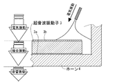
図11は、超音波振動子3とホーン4部分を示す。ホーン4は、アルミニウム等の導電性部材から成り、超音波振動子3の一方の電極3aが接続され、この電極3aと他方の電極3bとの間に電気振動信号が入力される。電気振動が機械振動に、さらに音響振動に変換される。
FIG. 11 shows the
図12は、上記のような超音波プローブの使用法を示す。超音波プローブ1は、広域な被処理面積に超音波を伝播させ、また、安全のために同一箇所へ超音波を集中させないために、生体10の被処理部表面を滑らせて使用することが通常である。ところが、このようにして超音波プローブ1を被処理部表面で滑らせて使用すると、時間の経過に伴い、図示のように、ホーン4と、被処理部表面の間に介在していた超音波伝達媒体5の量が少なくなる。ここに、超音波振動子3からホーン4に伝播され、ホーン放射面から放射される超音波を、被処理部へ高効率に伝播させるためには、超音波伝達媒体5が必要である。
FIG. 12 shows how to use the ultrasonic probe as described above. The
ここで、超音波プローブのホーンにより発生される音波の現象について説明する。音波の現象として反射があり、2種の媒質の境界面における反射率、すなわち反射エネルギーと入射エネルギーとの比は、媒質の密度をρ、媒質中の音速度をcとすると、ρcは音響インピーダンスであり、二つの媒質の音響インピーダンスは、ρ1c1、ρ2c2となり、
反射率r={(ρ1c1−ρ2c2)/(ρ1c1+ρ2c2)}2
で与えられ、ρ1c1とρ2c2の差が大きいほど、界面で反射が起こる。
Here, the phenomenon of the sound wave generated by the horn of the ultrasonic probe will be described. There is reflection as a phenomenon of sound waves, and the reflectance at the boundary surface between two types of media, that is, the ratio between the reflected energy and the incident energy, ρ is the density of the medium and c is the sound velocity in the medium. The acoustic impedances of the two media are ρ1c1 and ρ2c2,
Reflectance r = {(ρ1c1−ρ2c2) / (ρ1c1 + ρ2c2)} 2
As the difference between ρ1c1 and ρ2c2 increases, reflection occurs at the interface.
一例では、アルミニウムの音響インピーダンスは、およそ17×106N・s/m3、空気はおよそ430N・s/m3、水はおよそ1.5×106N・s/m3であり、生体はほぼ水と等価とされる。ここから、空気と水(生体)、空気とアルミニウムの界面では音波がほとんど反射してしまうことが分かる。この反射を防ぐために、超音波伝達媒体が利用される。
In one example, the acoustic impedance of aluminum is approximately 17 × 10 6 N · s /
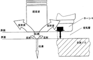
図13は、超音波伝達媒体が無い場合の音波の伝播現象を示す。ホーン4(例えば、アルミニウム製)を直接、生体10に接触させて超音波を伝達させるが、超音波伝達媒体が無いため、ホーン4と生体10との間には必ず空気層が存在してしまう。このため、ホーンと空気の界面、空気と生体の界面での音響インピーダンスの違いから、ほとんどの音波が界面で反射を起こし、超音波が生体内へ伝達されなくなる。超音波振動の伝達方向を図示矢印の方向で示し、振動振幅の大きさや超音波の強さを矢印の大きさで示しており、この場合、超音波が生体にほとんど伝達されないことが分かる。
FIG. 13 shows a sound wave propagation phenomenon when there is no ultrasonic transmission medium. The horn 4 (for example, made of aluminum) is directly brought into contact with the
図14は、超音波伝達媒体が有る場合の音波の伝播現象を示す。超音波伝達媒体5としては、通常、水や生体と等価な媒体が用いられ、ホーン4(例えばアルミニウム製)の超音波放射面と生体10との間に満たされる。これにより、ホーン4と生体10との間に存在していた空気層が無くなり、図示の矢印の幅で示したように、音波が界面でほとんど反射せずに、生体10に高効率に伝達されるようになる。
FIG. 14 shows the propagation phenomenon of sound waves when there is an ultrasonic transmission medium. As the
このように、超音波を高効率に生体に伝達させるためには、ホーンと被処理部との間に、常に超音波伝達媒体が存在することが不可欠であるが、超音波プローブは、ホーンと生体被処理部(例えば肌表面)を密着させ、かつ滑らせて使用するため、使用の間に超音波伝達媒体が減少し、超音波を伝達できなくなる。このため、常時、超音波伝達媒体を供給しながら超音波プローブを使用する必要があり、面倒である上に、超音波伝達媒体も無駄となる。 As described above, in order to transmit ultrasonic waves to a living body with high efficiency, it is indispensable that an ultrasonic transmission medium is always present between the horn and the processing target. Since the living body treated part (for example, the skin surface) is used in close contact with and slid, the ultrasonic transmission medium decreases during use, and ultrasonic waves cannot be transmitted. For this reason, it is necessary to always use the ultrasonic probe while supplying the ultrasonic transmission medium, which is cumbersome and wastes the ultrasonic transmission medium.
従って、超音波プローブを使用する上で、超音波伝達媒体をホーンと生体被処理部間に常に安定して存在させ、高効率に安定した超音波の伝達が達成できる超音波プローブの実現が望まれていた。 Therefore, when using an ultrasonic probe, it is desirable to realize an ultrasonic probe that can stably transmit ultrasonic waves with high efficiency by allowing an ultrasonic transmission medium to always exist stably between the horn and the living body processing part. It was rare.
本発明は、それに応えるもので、超音波プローブで生体肌表面又は生体内の被処理箇所を美容、治療、診断する上で、器具が大型化したりすることなく、超音波伝達媒体をホーンと生体被処理部間に維持させることができ、超音波プローブからの超音波を高効率、かつ安定して生体被処理部へ伝達することが可能な超音波美容器具を提供することを目的とする。 The present invention responds to this, and in the beauty, treatment, and diagnosis of a living body skin surface or a treatment site in a living body with an ultrasonic probe, an ultrasonic transmission medium is used as a horn and a living body without increasing the size of the instrument. It is an object of the present invention to provide an ultrasonic beauty instrument that can be maintained between processing parts and can transmit ultrasonic waves from an ultrasonic probe to a living body processing part with high efficiency and stability.
上記目的を達成するために、請求項1に係る発明は、超音波振動を生体肌表面に伝達させる超音波美容器具において、超音波振動を発生する超音波振動子と、前記超音波振動子からの超音波振動を伝達するホーンと、を備え、前記ホーンは、その表面に、器具使用時に該ホーンと生体肌表面との間に介在させる流動性を持つ超音波伝達媒体の流動を阻止する環状の凹部又は凸部の流動阻止構造を有し、前記環状の凹部又は凸部は前記超音波振動子と同心に形成され、前記環状の凹部又は凸部の内側円寸法が前記超音波振動子の外径寸法よりも大きいことを特徴とする。
また、請求項2に係る発明は、超音波振動を生体肌表面に伝達させる超音波美容器具において、超音波振動を発生する超音波振動子と、前記超音波振動子からの超音波振動を伝達するホーンと、を備え、前記超音波振動子は、中央部に穴が形成された円板型振動子であり、前記ホーンは、その表面に、前記超音波振動子の穴に対向するように形成された円形の凹部又は凸部を有し、前記超音波振動子の穴径が前記ホーンの表面に形成された円形の凹部又は凸部の直径以上であることを特徴とする。
なお、凹部又は凸部は、頂部に平坦部がある必要はなく、円錐状など錘状でも構わない。また、超音波伝達媒体は、美容器具とは別売りのものを想定している。
In order to achieve the above object, an invention according to
According to a second aspect of the present invention, there is provided an ultrasonic beauty instrument that transmits ultrasonic vibrations to the surface of a living body, an ultrasonic vibrator that generates ultrasonic vibrations, and ultrasonic vibrations transmitted from the ultrasonic vibrators. The ultrasonic vibrator is a disc-type vibrator having a hole formed in the center thereof, and the horn faces the hole of the ultrasonic vibrator on the surface thereof. It has the formed circular recessed part or convex part, and the hole diameter of the said ultrasonic vibrator is more than the diameter of the circular recessed part or convex part formed in the surface of the said horn, It is characterized by the above-mentioned .
The concave portion or the convex portion does not need to have a flat portion at the top portion, and may have a conical shape such as a conical shape. The ultrasonic transmission medium is assumed to be sold separately from the beauty tool.
請求項3に係る発明は、請求項2記載の超音波美容器具において、前記ホーンは、その表面に、前記円形の凹部又は凸部の外側に形成され、器具使用時に該ホーンと生体肌表面との間に介在させる流動性を持つ超音波伝達媒体の流動を阻止する環状の凹部又は凸部の流動阻止構造を有し、前記超音波振動子の外径が前記環状の凹部又は凸部の内径以下であることを特徴とする。According to a third aspect of the present invention, in the ultrasonic beauty instrument according to the second aspect, the horn is formed on the surface of the outer side of the circular concave portion or the convex portion, and the horn and the living body skin surface are used when the instrument is used. An annular recess or projection that blocks the flow of an ultrasonic transmission medium having fluidity interposed between the two, and the outer diameter of the ultrasonic transducer is the inner diameter of the annular recess or projection It is characterized by the following.
請求項4に係る発明は、請求項1乃至3のいずれか1項に記載の超音波美容器具において、前記超音波振動子とホーンの振動方向厚みが、超音波の1/4波長の整数倍とされ、前記凹凸形状が超音波の1/4波長の整数倍を外した高さとされていることを特徴とする。According to a fourth aspect of the present invention, in the ultrasonic cosmetic device according to any one of the first to third aspects, the thickness in the vibration direction of the ultrasonic transducer and the horn is an integral multiple of a quarter wavelength of the ultrasonic wave. The concave and convex shape is characterized by having a height excluding an integral multiple of a quarter wavelength of the ultrasonic wave.
本発明によれば、ホーン自体の表面に凹凸形状を設けたことで、超音波伝達媒体の流動をできるだけ少なくして、超音波伝達媒体を被処理部分表面に維持させることができるので、従来のように、超音波伝達媒体を入れる袋体を別個に設けるといった必要がなくなり低コスト化を図りつつ、ホーンと被処理部表面との間に介在する空気層を無くし、高効率かつ安定して超音波を被処理部分へ伝達させることができ、常に安定した超音波美容、治療、診断ができるようになる。ホーンと被処理部表面との間に介在させた超音波伝達媒体は窪みや穴に入り込み、被処理部分外に排除されないで維持することができる。 According to the present invention, by providing an uneven shape on the surface of the horn itself, the flow of the ultrasonic transmission medium can be reduced as much as possible, and the ultrasonic transmission medium can be maintained on the surface of the processing target. Thus, there is no need to separately provide a bag for containing the ultrasonic transmission medium, and the air layer interposed between the horn and the surface of the treated part is eliminated while reducing the cost, so that the super Sound waves can be transmitted to the part to be processed, and stable ultrasonic beauty, treatment, and diagnosis can be performed at all times. The ultrasonic transmission medium interposed between the horn and the surface of the processing part enters the recess or the hole and can be maintained without being excluded outside the processing part.
また、プローブを滑らせる使用方法は、方向や動かし方に規則性がないため、ホーンに設ける凸部や窪みや穴をホーン中心を基準として略点対称もしくは線対称にすることで、方向や動かし方に関わらず、安定して超音波を伝達させることができる。また、凹凸形状が略対称であることにより、例えば、円板型振動子(リング状振動子をも含む)に円環状の凹凸形状(凹溝)であることで、超音波伝達媒体を効率的に維持できる。 Also, since the usage method of sliding the probe is not regular in direction and movement, the direction and movement can be achieved by making the protrusions, depressions and holes provided in the horn substantially point symmetric or line symmetric with respect to the horn center. Regardless of the direction, ultrasonic waves can be transmitted stably. In addition, since the concavo-convex shape is substantially symmetrical, for example, the disk-shaped vibrator (including the ring-shaped vibrator) has an annular concavo-convex shape (concave groove), so that the ultrasonic transmission medium can be efficiently used. Can be maintained.
また、凹凸形状が閉ループ(円環状、四角の囲みなどであるが、一部が切れているものをも含む)であれば、ホーンの端部から超音波伝達媒体が出て行くのを防止することができる。 Also, if the concavo-convex shape is a closed loop (including an annular shape, a square box, etc., including a part that is cut off), the ultrasonic transmission medium is prevented from exiting from the end of the horn. be able to.
また、ホーンに設けられた凹凸の寸法設定により、ホーンに設けた窪みや穴が本来の超音波振動を妨げることなく、窪み又は穴や凸部の共振を防ぎ、不要な振動の発生を防ぐことができ、かつ、超音波伝達媒体をホーンと被処理部分との間に維持させることができる。 In addition, by setting the dimensions of the unevenness provided in the horn, the depression or hole provided in the horn does not interfere with the original ultrasonic vibration, and the resonance of the depression or hole or protrusion is prevented, thereby preventing the occurrence of unnecessary vibration. And the ultrasonic transmission medium can be maintained between the horn and the portion to be processed.
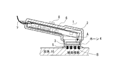
以下、本発明の実施形態による超音波美容器具について図面を参照して説明する。図1は、超音波美容器具、すなわち、超音波プローブの構成を、図2は同プローブのホーン部の構成を示し、いずれも器具使用状態を示す。超音波プローブ1は、そのハウジング2と、超音波振動の駆動源となる超音波振動子3と、その超音波振動を生体10の肌表面又は生体内の目的箇所つまり被処理部に伝達させるホーン4と、超音波振動子3を駆動する駆動回路6を有している。ここに、ホーン4と生体10の被処理部との間に、オリーブ油等のゲル状物質で成る超音波伝達媒体5を常時介在させた状態で超音波を被処理部に伝達させる。それにより、ホーン4と生体10の被処理部との間に空気層が介在しなくなり、高効率に超音波を伝達することができる。
Hereinafter, an ultrasonic beauty instrument according to an embodiment of the present invention will be described with reference to the drawings. FIG. 1 shows the configuration of an ultrasonic beauty instrument, that is, an ultrasonic probe, and FIG. 2 shows the configuration of the horn part of the probe, both of which show the use state of the instrument. The
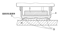
ホーン4と生体10の被処理部との間に超音波伝達媒体5を常時介在させた状態とするために、図2に示すように、超音波伝達媒体5を維持するための構造として、プローブ内のホーン4の被処理部対向平面に凹凸形状9(凸部や窪みや穴も含む)を設けた。ホーン4は、本実施形態では、アルミニウム等の材質で有底筒状に形成され、扁平円板状の超音波振動子3を貼り付けた型の振動ブロックを示したが、ボルト締め(ランジュバン型を含む)振動子を用いた構成であってもよい。好ましい実施形態では、ホーン4と超音波振動子3は、超音波の定在波振動体を構成している。なお、ハウジング2には、電源ケーブル7が導出され、また、動作スイッチ8が設けられている。ホーン4は、ハウジング2の開口に取り付けられる。
As shown in FIG. 2, a probe is used as a structure for maintaining the
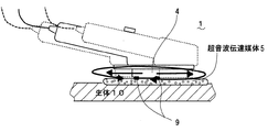
超音波プローブ1は、被処理部分表面を滑らせて移動させながら使用する。図3は、そうして使用した場合を示す。当初、超音波伝達媒体5は、ユーザによりホーン4の被処理部対向面に適当量を塗布される。超音波伝達媒体5は、上記のホーン4の凹凸形状9により流動が阻止され、被処理部対向面に維持されるので、時間経過後においても、ホーン4と生体10との間に空気層が生じることがなくなる。そのため、ホーン4は超音波伝達媒体5を介在させて超音波を高効率かつ安定して被処理部へ伝達することができ、また、インピーダンス周波数特性も安定し、安定駆動ができる。ちなみに、凹凸形状9がない場合は、ホーン4と被処理部分との間に介在させた超音波伝達媒体5が少なくなるため、空気層が生じて界面での音響インピーダンスの大幅な相違により、音波の反射が起こり、超音波の伝達効率が低下する。
The
本実施形態による超音波プローブによれば、ホーン4に直接設けた凹凸形状により超音波伝達媒体5をホーン4と被処理部表面との間に維持させることができ、そのため、空気層を無くして、音響インピーダンスの大幅な相違による音波の反射を抑えるとともに、インピーダンス周波数特性も安定させることができるため、常時、高効率な超音波の伝達や安定駆動ができ、安全に使用することができる。
According to the ultrasonic probe according to the present embodiment, the
図4、図5は、ホーン4と被処理部分との間に超音波伝達媒体5を維持するための構造の他実施形態を示す。図4には、ホーン4の表面に凹凸形状として凸部91を設けた例、図5には、ホーン4の表面に凸部91と窪み(又は穴)92を設けた例をそれぞれ示す。好ましくは、凸部や窪み又は穴は、ホーン4の中心を基準として略点対称又は線対称とする。
4 and 5 show another embodiment of the structure for maintaining the
図6は、窪み92の各種実施形態を示す。窪み92(凸部でも構わない)が略点対称又は線対称に配置されることにより、ホーン4と被処理部表面との間に介在させた超音波伝達媒体5は、窪み92に入り込み、被処理部分外に排除されないで維持される。プローブ1を滑らせる使用方法は、その方向や動かし方に規則性がないことから、ホーン4に設ける凸部や窪みや穴が、上記のように略点対称又は線対称であることは好都合である。さらに、プローブ1の使用中に生体を傷つけることを防ぐため、凸部や窪みや穴の角部は面取り(R含む)することが望ましい。これにより、プローブ1の如何なる不規則な動きにも追従して効果的な超音波伝達が可能となる。
FIG. 6 shows various embodiments of the
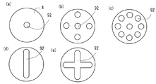
上記のように、ホーン4に設けられる凸部91や窪み92又は穴は、円状又は環状に設置している。このとき、好ましい条件としては、図7(a)(b)(c)に示すように、環状の窪み(凹部)92又は凸部91の内側円寸法φ2が、超音波振動子3の外径寸法φ1よりも大きく、同心であることが望ましい。また、図7(d)に示すように、環状の窪み92又は凸部91は、一部が切れていても構わない。図7(a)の矢印で示すように、超音波振動子3の振動は、超音波伝達媒体5を介して生体10に高効率に伝達される。
As described above, the
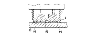
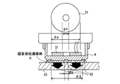
また、図8に示すように、超音波振動子3として、円板型振動子31を用いてもよい。この場合、円板型振動子31の穴径φAは、円状の窪み92又は凸部91の穴径φC以上で、かつ同心であることが望ましい。また、円板型振動子31の外径φBは、環状の窪み92又は凸部91の内径φD以下であることが望ましい。これらにより、ホーン4に設けた窪み92等が本来の超音波振動を妨げることなく、かつ超音波伝達媒体5をホーン4と生体10の被処理部分との間に維持させることができる。
Further, as shown in FIG. 8, a disk-
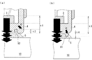
図9(a)(b)は、超音波プローブ1における超音波振動子3とホーン4の適正な高さ寸法を示す。ホーン4の表面に設けた窪み92(又は穴)や凸部91は、ホーン4の共振動作に伴い不要な振動を発生する要因となる。この不要な超音波振動を矢印Eで示す。この不要な振動を阻止するため、ホーン4に設けた窪み92又は穴の深さt2や凸部91の高さ寸法t4は、超音波の1/4波長の整数倍を外した寸法に設計する。また、超音波振動子3とホーン4の振動方向厚みt1,t3は、通常、超音波の1/4波長の整数倍の寸法に形成する。また、好ましくは、窪み92又は穴の深さや凸部91の高さは、超音波の1/4波長以下の寸法にする。こうして、ホーン4の窪み92又は穴や凸部91の共振を防ぎ、不要な振動の発生を防ぐことができる。
FIGS. 9A and 9B show appropriate height dimensions of the
なお、本発明は前述した事柄及び図示のものに限定されるわけではなく、超音波プローブに超音波伝達媒体を維持させる構造をホーン自体に設け、生体の被処理部に超音波伝達効率を上げるようにしたものであれば、発明の精神及び特許請求の範囲に逸脱することなく、様々な変形を取ることができる。 Note that the present invention is not limited to the above-described matters and those shown in the drawings. The horn itself is provided with a structure that allows the ultrasonic probe to maintain the ultrasonic transmission medium, and the ultrasonic transmission efficiency is increased in the target portion of the living body. If it does, various modifications can be made without departing from the spirit of the invention and the scope of the claims.
1 超音波プローブ
2 ハウジング
3 超音波振動子
31 円板型振動子
4 ホーン
5 超音波伝達媒体
9 凹凸形状
91 窪み
92 凸部
10 生体
DESCRIPTION OF
Claims (4)
超音波振動を発生する超音波振動子と、
前記超音波振動子からの超音波振動を伝達するホーンと、を備え、
前記ホーンは、その表面に、器具使用時に該ホーンと生体肌表面との間に介在させる流動性を持つ超音波伝達媒体の流動を阻止する環状の凹部又は凸部の流動阻止構造を有し、
前記環状の凹部又は凸部は前記超音波振動子と同心に形成され、前記環状の凹部又は凸部の内側円寸法が前記超音波振動子の外径寸法よりも大きいことを特徴とする超音波美容器具。 In ultrasonic beauty instruments that transmit ultrasonic vibrations to the surface of living skin,
An ultrasonic transducer that generates ultrasonic vibrations;
A horn for transmitting ultrasonic vibration from the ultrasonic vibrator, and
The horn has, on its surface, an annular concave or convex flow blocking structure for blocking the flow of an ultrasonic transmission medium having fluidity to be interposed between the horn and the biological skin surface when using the instrument ,
The annular recess or projection is formed concentrically with the ultrasonic transducer, and the inner circular dimension of the annular recess or projection is larger than the outer diameter of the ultrasonic transducer. Beauty equipment.
超音波振動を発生する超音波振動子と、
前記超音波振動子からの超音波振動を伝達するホーンと、を備え、
前記超音波振動子は、中央部に穴が形成された円板型振動子であり、
前記ホーンは、その表面に、前記超音波振動子の穴に対向するように形成された円形の凹部又は凸部を有し、
前記超音波振動子の穴径が前記ホーンの表面に形成された円形の凹部又は凸部の直径以上であることを特徴とする超音波美容器具。 In ultrasonic beauty instruments that transmit ultrasonic vibrations to the surface of living skin,
An ultrasonic transducer that generates ultrasonic vibrations;
A horn for transmitting ultrasonic vibration from the ultrasonic vibrator, and
The ultrasonic vibrator is a disk-type vibrator having a hole formed in the center,
The horn has a circular recess or projection formed on the surface so as to face the hole of the ultrasonic transducer,
An ultrasonic beauty instrument characterized in that a hole diameter of the ultrasonic vibrator is equal to or larger than a diameter of a circular concave portion or convex portion formed on the surface of the horn .
前記超音波振動子の外径が前記環状の凹部又は凸部の内径以下であることを特徴とする請求項2記載の超音波美容器具。 The horn is formed on the outer surface of the circular concave portion or convex portion on the surface thereof, and prevents the flow of an ultrasonic transmission medium having fluidity to be interposed between the horn and the living body skin surface when using the instrument. Having a flow blocking structure of the concave or convex portion of
The ultrasonic beauty instrument according to claim 2, wherein an outer diameter of the ultrasonic transducer is equal to or smaller than an inner diameter of the annular concave portion or convex portion .
Priority Applications (1)
| Application Number | Priority Date | Filing Date | Title |
|---|---|---|---|
| JP2004140457A JP4100372B2 (en) | 2004-05-10 | 2004-05-10 | Ultrasonic beauty equipment |
Applications Claiming Priority (1)
| Application Number | Priority Date | Filing Date | Title |
|---|---|---|---|
| JP2004140457A JP4100372B2 (en) | 2004-05-10 | 2004-05-10 | Ultrasonic beauty equipment |
Publications (2)
| Publication Number | Publication Date |
|---|---|
| JP2005323213A JP2005323213A (en) | 2005-11-17 |
| JP4100372B2 true JP4100372B2 (en) | 2008-06-11 |
Family
ID=35470140
Family Applications (1)
| Application Number | Title | Priority Date | Filing Date |
|---|---|---|---|
| JP2004140457A Expired - Fee Related JP4100372B2 (en) | 2004-05-10 | 2004-05-10 | Ultrasonic beauty equipment |
Country Status (1)
| Country | Link |
|---|---|
| JP (1) | JP4100372B2 (en) |
Families Citing this family (49)
| Publication number | Priority date | Publication date | Assignee | Title |
|---|---|---|---|---|
| US6050943A (en) | 1997-10-14 | 2000-04-18 | Guided Therapy Systems, Inc. | Imaging, therapy, and temperature monitoring ultrasonic system |
| US7914453B2 (en) | 2000-12-28 | 2011-03-29 | Ardent Sound, Inc. | Visual imaging system for ultrasonic probe |
| US8235909B2 (en) | 2004-05-12 | 2012-08-07 | Guided Therapy Systems, L.L.C. | Method and system for controlled scanning, imaging and/or therapy |
| US7393325B2 (en) | 2004-09-16 | 2008-07-01 | Guided Therapy Systems, L.L.C. | Method and system for ultrasound treatment with a multi-directional transducer |
| US7824348B2 (en) | 2004-09-16 | 2010-11-02 | Guided Therapy Systems, L.L.C. | System and method for variable depth ultrasound treatment |
| US9011336B2 (en) | 2004-09-16 | 2015-04-21 | Guided Therapy Systems, Llc | Method and system for combined energy therapy profile |
| US10864385B2 (en) | 2004-09-24 | 2020-12-15 | Guided Therapy Systems, Llc | Rejuvenating skin by heating tissue for cosmetic treatment of the face and body |
| US8535228B2 (en) | 2004-10-06 | 2013-09-17 | Guided Therapy Systems, Llc | Method and system for noninvasive face lifts and deep tissue tightening |
| US8444562B2 (en) | 2004-10-06 | 2013-05-21 | Guided Therapy Systems, Llc | System and method for treating muscle, tendon, ligament and cartilage tissue |
| US20120165668A1 (en) | 2010-08-02 | 2012-06-28 | Guided Therapy Systems, Llc | Systems and methods for treating acute and/or chronic injuries in soft tissue |
| US9694212B2 (en) | 2004-10-06 | 2017-07-04 | Guided Therapy Systems, Llc | Method and system for ultrasound treatment of skin |
| JP2008522642A (en) | 2004-10-06 | 2008-07-03 | ガイデッド セラピー システムズ, エル.エル.シー. | Method and system for beauty enhancement |
| US9827449B2 (en) | 2004-10-06 | 2017-11-28 | Guided Therapy Systems, L.L.C. | Systems for treating skin laxity |
| US20060111744A1 (en) | 2004-10-13 | 2006-05-25 | Guided Therapy Systems, L.L.C. | Method and system for treatment of sweat glands |
| US11235179B2 (en) | 2004-10-06 | 2022-02-01 | Guided Therapy Systems, Llc | Energy based skin gland treatment |
| PL2409728T3 (en) | 2004-10-06 | 2018-01-31 | Guided Therapy Systems Llc | System for ultrasound tissue treatment |
| US8690778B2 (en) | 2004-10-06 | 2014-04-08 | Guided Therapy Systems, Llc | Energy-based tissue tightening |
| US7758524B2 (en) | 2004-10-06 | 2010-07-20 | Guided Therapy Systems, L.L.C. | Method and system for ultra-high frequency ultrasound treatment |
| US8133180B2 (en) | 2004-10-06 | 2012-03-13 | Guided Therapy Systems, L.L.C. | Method and system for treating cellulite |
| US11883688B2 (en) | 2004-10-06 | 2024-01-30 | Guided Therapy Systems, Llc | Energy based fat reduction |
| US11724133B2 (en) | 2004-10-07 | 2023-08-15 | Guided Therapy Systems, Llc | Ultrasound probe for treatment of skin |
| US11207548B2 (en) | 2004-10-07 | 2021-12-28 | Guided Therapy Systems, L.L.C. | Ultrasound probe for treating skin laxity |
| US7571336B2 (en) | 2005-04-25 | 2009-08-04 | Guided Therapy Systems, L.L.C. | Method and system for enhancing safety with medical peripheral device by monitoring if host computer is AC powered |
| US9566454B2 (en) | 2006-09-18 | 2017-02-14 | Guided Therapy Systems, Llc | Method and sysem for non-ablative acne treatment and prevention |
| US9241683B2 (en) | 2006-10-04 | 2016-01-26 | Ardent Sound Inc. | Ultrasound system and method for imaging and/or measuring displacement of moving tissue and fluid |
| JP2010526589A (en) | 2007-05-07 | 2010-08-05 | ガイデッド セラピー システムズ, エル.エル.シー. | Method and system for modulating a mediant using acoustic energy |
| WO2008137944A1 (en) | 2007-05-07 | 2008-11-13 | Guided Therapy Systems, Llc. | Methods and systems for coupling and focusing acoustic energy using a coupler member |
| PT3058875T (en) | 2008-06-06 | 2022-09-20 | Ulthera Inc | A system and method for cosmetic treatment and imaging |
| US12102473B2 (en) | 2008-06-06 | 2024-10-01 | Ulthera, Inc. | Systems for ultrasound treatment |
| CA2748362A1 (en) | 2008-12-24 | 2010-07-01 | Michael H. Slayton | Methods and systems for fat reduction and/or cellulite treatment |
| US8715186B2 (en) | 2009-11-24 | 2014-05-06 | Guided Therapy Systems, Llc | Methods and systems for generating thermal bubbles for improved ultrasound imaging and therapy |
| KR101117311B1 (en) * | 2009-12-11 | 2012-03-19 | 김희구 | Trans-dermal drug delivery system of apparatus for skin massage |
| US9504446B2 (en) | 2010-08-02 | 2016-11-29 | Guided Therapy Systems, Llc | Systems and methods for coupling an ultrasound source to tissue |
| US8857438B2 (en) | 2010-11-08 | 2014-10-14 | Ulthera, Inc. | Devices and methods for acoustic shielding |
| RU2504330C2 (en) | 2011-03-24 | 2014-01-20 | Магомед Хабибович Магомедов | Device for monitoring chewing movements (versions) and earphone |
| WO2013009784A2 (en) | 2011-07-10 | 2013-01-17 | Guided Therapy Systems, Llc | Systems and method for accelerating healing of implanted material and/or native tissue |
| KR20190080967A (en) | 2011-07-11 | 2019-07-08 | 가이디드 테라피 시스템스, 엘.엘.씨. | Systems and methods for coupling an ultrasound source to tissue |
| US9263663B2 (en) | 2012-04-13 | 2016-02-16 | Ardent Sound, Inc. | Method of making thick film transducer arrays |
| US9510802B2 (en) | 2012-09-21 | 2016-12-06 | Guided Therapy Systems, Llc | Reflective ultrasound technology for dermatological treatments |
| CN104027893B (en) | 2013-03-08 | 2021-08-31 | 奥赛拉公司 | Apparatus and method for multi-focal ultrasound therapy |
| US10561862B2 (en) | 2013-03-15 | 2020-02-18 | Guided Therapy Systems, Llc | Ultrasound treatment device and methods of use |
| AU2015247951A1 (en) | 2014-04-18 | 2016-11-17 | Ulthera, Inc. | Band transducer ultrasound therapy |
| DK3405294T3 (en) | 2016-01-18 | 2023-03-13 | Ulthera Inc | COMPACT ULTRASOUND DEVICE WITH RING-SHAPED ULTRASOUND MATRIX WITH PERIPHERAL ELECTRICAL CONNECTION FOR FLEXIBLE PRINT BOARD |
| KR102593310B1 (en) | 2016-08-16 | 2023-10-25 | 얼테라, 인크 | Ultrasound imaging system configured to reduce imaging misalignment, ultrasound imaging module, and method for reducing imaging misalignment |
| TW202327520A (en) | 2018-01-26 | 2023-07-16 | 美商奧賽拉公司 | Systems and methods for simultaneous multi-focus ultrasound therapy in multiple dimensions |
| US11944849B2 (en) | 2018-02-20 | 2024-04-02 | Ulthera, Inc. | Systems and methods for combined cosmetic treatment of cellulite with ultrasound |
| CN108722326B (en) * | 2018-08-07 | 2020-04-03 | 深圳市蓓媞科技有限公司 | Vibration assembly, beauty device with vibration assembly and using method of beauty device |
| CN109316328B (en) * | 2018-09-29 | 2021-06-04 | 深圳市蓓媞科技有限公司 | Cosmetic device |
| WO2024025014A1 (en) * | 2022-07-29 | 2024-02-01 | 엘지전자 주식회사 | Physical therapy device |
-
2004
- 2004-05-10 JP JP2004140457A patent/JP4100372B2/en not_active Expired - Fee Related
Also Published As
| Publication number | Publication date |
|---|---|
| JP2005323213A (en) | 2005-11-17 |
Similar Documents
| Publication | Publication Date | Title |
|---|---|---|
| JP4100372B2 (en) | Ultrasonic beauty equipment | |
| US6925187B2 (en) | Horn array emitter | |
| US5581144A (en) | Miniature, high efficiency dual frequency ultrasonic transducer with selectable beamwidth and apparatus | |
| JP4319400B2 (en) | Ultrasonic core bit | |
| JP2005516512A (en) | Method and apparatus for focusing ultrasonic energy | |
| CA2590057A1 (en) | Ultrasonic medical treatment device with variable focal zone | |
| WO2008047743A1 (en) | Ultrasonic sensor | |
| ES2938849T3 (en) | multi-cell transducer | |
| JP6774697B1 (en) | Ultrasonic irradiator | |
| JP2019025628A (en) | Ultrasonic vibration machining device | |
| JP2007155675A (en) | Ultrasonic sensor | |
| JP4936187B2 (en) | Beauty equipment | |
| JPS59501888A (en) | Speakers, especially high-pitched speakers | |
| RU2332266C1 (en) | Ultrasonic vibration system | |
| JPH06511131A (en) | Sonic or ultrasonic transducer | |
| KR101861354B1 (en) | Focused Ultrasonic Transducer | |
| JP3972610B2 (en) | Ultrasonic beauty device | |
| JP6707242B1 (en) | Array type parametric speaker | |
| JP2814817B2 (en) | Low frequency underwater ultrasonic transmitter | |
| JP2007301023A (en) | Ultrasonic probe | |
| JP4419774B2 (en) | Ultrasonic beauty equipment | |
| JPH09271098A (en) | Electro-acoustic transducer | |
| JP2001258088A5 (en) | ||
| JP4639306B2 (en) | Air gap hydrophone | |
| WO2023007811A1 (en) | Oscillating wave radiator |
Legal Events
| Date | Code | Title | Description |
|---|---|---|---|
| A621 | Written request for application examination |
Free format text: JAPANESE INTERMEDIATE CODE: A621 Effective date: 20060414 |
|
| A131 | Notification of reasons for refusal |
Free format text: JAPANESE INTERMEDIATE CODE: A131 Effective date: 20071204 |
|
| A521 | Written amendment |
Free format text: JAPANESE INTERMEDIATE CODE: A523 Effective date: 20080130 |
|
| TRDD | Decision of grant or rejection written | ||
| A01 | Written decision to grant a patent or to grant a registration (utility model) |
Free format text: JAPANESE INTERMEDIATE CODE: A01 Effective date: 20080226 |
|
| A61 | First payment of annual fees (during grant procedure) |
Free format text: JAPANESE INTERMEDIATE CODE: A61 Effective date: 20080310 |
|
| FPAY | Renewal fee payment (event date is renewal date of database) |
Free format text: PAYMENT UNTIL: 20110328 Year of fee payment: 3 |
|
| R150 | Certificate of patent or registration of utility model |
Free format text: JAPANESE INTERMEDIATE CODE: R150 |
|
| S533 | Written request for registration of change of name |
Free format text: JAPANESE INTERMEDIATE CODE: R313533 |
|
| FPAY | Renewal fee payment (event date is renewal date of database) |
Free format text: PAYMENT UNTIL: 20110328 Year of fee payment: 3 |
|
| R350 | Written notification of registration of transfer |
Free format text: JAPANESE INTERMEDIATE CODE: R350 |
|
| FPAY | Renewal fee payment (event date is renewal date of database) |
Free format text: PAYMENT UNTIL: 20120328 Year of fee payment: 4 |
|
| FPAY | Renewal fee payment (event date is renewal date of database) |
Free format text: PAYMENT UNTIL: 20120328 Year of fee payment: 4 |
|
| FPAY | Renewal fee payment (event date is renewal date of database) |
Free format text: PAYMENT UNTIL: 20130328 Year of fee payment: 5 |
|
| FPAY | Renewal fee payment (event date is renewal date of database) |
Free format text: PAYMENT UNTIL: 20130328 Year of fee payment: 5 |
|
| FPAY | Renewal fee payment (event date is renewal date of database) |
Free format text: PAYMENT UNTIL: 20140328 Year of fee payment: 6 |
|
| LAPS | Cancellation because of no payment of annual fees |
