JP4100321B2 - Segment unit image encoding apparatus and segment unit image encoding program - Google Patents
Segment unit image encoding apparatus and segment unit image encoding program Download PDFInfo
- Publication number
- JP4100321B2 JP4100321B2 JP2003356693A JP2003356693A JP4100321B2 JP 4100321 B2 JP4100321 B2 JP 4100321B2 JP 2003356693 A JP2003356693 A JP 2003356693A JP 2003356693 A JP2003356693 A JP 2003356693A JP 4100321 B2 JP4100321 B2 JP 4100321B2
- Authority
- JP
- Japan
- Prior art keywords
- block
- segment
- value
- blocks
- small
- Prior art date
- Legal status (The legal status is an assumption and is not a legal conclusion. Google has not performed a legal analysis and makes no representation as to the accuracy of the status listed.)
- Expired - Fee Related
Links
Images


Description
本発明はセグメント単位画像符号化装置及びセグメント単位画像符号化プログラムに係り、特にテレビ画像など時間的に連続する2次元画像を矩形領域や任意形状領域に分割し、前記領域単位に符号化するセグメント単位画像符号化装置及びセグメント単位画像符号化プログラムに関する。 The present invention relates to a segment unit image encoding apparatus and a segment unit image encoding program, and in particular, a segment for dividing a temporally continuous two-dimensional image such as a television image into rectangular regions or arbitrary shape regions and encoding the regions. The present invention relates to a unit image encoding device and a segment unit image encoding program.
従来、ディジタル記録装置やディジタル放送などに代表される画像高能率符号化方式として、MPEG(Moving Picture Experts Group)方式が広く用いられている。このMPEG方式では、2次元画像を既知の矩形領域(ブロック)に分割して符号化する。これに対して、圧縮効率の改善を目的とした任意形状領域の符号化方法としてセグメント単位画像符号化方法も従来より知られている(例えば、特許文献1参照)。この特許文献1には、図案の輝度と色差を特徴量として隣接画素を統合し、2種類のセグメンテーション画像を作成し、それぞれに特徴的なこれら2種類のセグメンテーション画像を組み合わせることで符号化効率の向上を図っている。
Conventionally, the MPEG (Moving Picture Experts Group) method has been widely used as an image high-efficiency encoding method typified by digital recording devices and digital broadcasting. In this MPEG system, a two-dimensional image is divided into known rectangular areas (blocks) and encoded. On the other hand, a segment-unit image encoding method has been conventionally known as an encoding method for an arbitrarily shaped region for the purpose of improving compression efficiency (see, for example, Patent Document 1). In this
上記のセグメントを単位とした動画像のセグメント単位画像符号化では、従来のブロックベースの符号化と同様に、フレーム間の動き検出によるセグメントのマッチングをとりながら符号化を行う。この方法は、セグメントが剛体で、かつ、フレーム間で見かけ上の大きさが変化しない場合には、大変効率の良い方法である。 In the segment-unit image encoding of a moving image using the above-mentioned segment as a unit, encoding is performed while matching segments by detecting motion between frames as in the conventional block-based encoding. This method is very efficient when the segment is a rigid body and the apparent size does not change between frames.
しかし、実映像で物体が移動する場合には、撮影しているカメラから物体までの距離の変化や他物体との隠蔽が発生するため、セグメントの大きさや形状が変化しないことは稀である。このため、正確なセグメントの抽出は計算量が増大する割には符号量の削減効果が薄いという問題がある。更に、前フレームで異なる位置にあった2つの物体が、次フレームで近接する位置に移動した場合、照明条件の違うものが並存することやオーバーラップが発生し、セグメント境界が不自然に見えるという問題もある。 However, when an object moves in a real image, a change in the distance from the camera being photographed to the object or a concealment with another object occurs, so it is rare that the size or shape of the segment does not change. For this reason, accurate segment extraction has a problem that the effect of reducing the amount of code is small for an increase in calculation amount. Furthermore, when two objects that were in different positions in the previous frame move to positions that are close in the next frame, objects with different illumination conditions coexist and overlap occurs, and segment boundaries look unnatural. There is also a problem.
本発明は以上の点に鑑みなされたもので、セグメントベース符号化の特徴である符号化効率の良さを損なわずに、フレーム間でセグメント形状が変化する場合の符号化効率の極端な低下を防止し得るセグメント単位画像符号化装置及びセグメント単位画像符号化プログラムを提供することを目的とする。 The present invention has been made in view of the above points, and prevents an extreme decrease in coding efficiency when the segment shape changes between frames without losing the good coding efficiency characteristic of segment-based coding. An object of the present invention is to provide a segment unit image encoding apparatus and a segment unit image encoding program.
上記の目的を達成するため、第1の発明のセグメント単位画像符号化装置は、供給される画像信号の2次元画像を複数のブロックに分割してブロック単位に符号化するセグメント単位画像符号化装置であって、供給される画像信号の2次元画像を第1の形状サイズのブロックの単位で分割する第1の分割手段と、第1の分割手段により分割されたブロック内の画素が持つ輝度値及び色差値の少なくとも一方の平均値と分散値の組み合わせをブロック特徴量として、各ブロック毎に算出する第1の算出手段と、ブロック特徴量が規定値より大きな値を持つブロックは孤立ブロックとして残し、ブロック特徴量が規定値以下の値を持つブロックのうち、ブロック特徴量が近似した値を持つ隣接ブロック同士を統合してセグメントとして作成する第1のセグメント作成手段と、第1のセグメント作成手段から出力される信号を入力として受け、セグメント単位及び孤立ブロック単位に所定の符号化を行って符号化データを出力する符号化手段とを有する構成としたものである。 In order to achieve the above object, a segment unit image encoding apparatus according to a first aspect of the present invention is a segment unit image encoding apparatus that divides a two-dimensional image of a supplied image signal into a plurality of blocks and encodes them in block units. A first dividing unit that divides a two-dimensional image of the supplied image signal in units of blocks of the first shape size, and a luminance value that a pixel in the block divided by the first dividing unit has And a first calculation means for calculating for each block using a combination of at least one of the average value and the color difference value and the variance value as a block feature amount, and blocks having a block feature amount larger than a specified value are left as isolated blocks. , Among the blocks whose block feature value is less than or equal to the specified value, adjacent blocks having values that approximate the block feature value are integrated to create a segment. And a coding unit that receives a signal output from the first segment generation unit as an input, performs predetermined encoding in segment units and isolated block units, and outputs encoded data. It is a thing.
この発明では、符号化される画像信号の2次元画像をブロックに分割し、ブロック毎に算出したブロック特徴量が規定値以下で、かつ、互いに近い値を持つ隣接ブロック同士を統合してセグメントを作成する一方で、分散が規定値より大きな値になる輝度エッジや色変化のある画像輪郭周辺部を含むブロックを孤立ブロックとして残すことで、フレーム間でセグメントの大きさや形状が異なる場合でも、2次元画像の物体内部と物体画像輪郭周辺部を別セグメントになるようなブロックベースのセグメンテーションを実現することができる。 In this invention, the two-dimensional image of the image signal to be encoded is divided into blocks, and the segment is calculated by integrating adjacent blocks having block feature values calculated for each block that are equal to or less than a specified value and close to each other. On the other hand, even if the size and shape of the segment differs between frames by leaving a block including a luminance edge whose variance is larger than a specified value and a peripheral portion of the image contour having a color change as an isolated block, 2 It is possible to realize block-based segmentation such that the inside of the object of the dimensional image and the periphery of the object image contour are separated into different segments.
また、上記の目的を達成するため、第2の発明のセグメント単位画像符号化装置は、第1の発明の構成に加えて、第1のセグメント作成手段から出力される孤立ブロックを、第1の形状サイズより小である第2の形状サイズの小ブロックの単位で分割する第2の分割手段と、第2の分割手段により分割された小ブロック内の画素が持つ輝度値及び色差値の少なくとも一方の平均値と分散値の組み合わせをブロック特徴量として、各小ブロック毎に算出する第2の算出手段と、第2の算出手段により算出されたブロック特徴量が規定値より大きな値を持つ小ブロックは孤立小ブロックとして残し、ブロック特徴量が規定値以下の値を持つ小ブロックのうち、ブロック特徴量が近似した値を持つ隣接する小ブロック又はセグメントと統合して新たなセグメントを作成する第2のセグメント作成手段と
を更に有し、符号化手段は、第2のセグメント作成手段から出力される信号を入力として受け、新たなセグメント単位及び孤立小ブロック単位に所定の符号化を行って符号化データを出力することを特徴とする。
In order to achieve the above object, the segment unit image coding apparatus according to the second aspect of the invention adds the isolated block output from the first segment creating means to the first block in addition to the configuration of the first aspect of the invention. At least one of a luminance value and a color difference value possessed by a second dividing unit that divides in units of small blocks of a second shape size that is smaller than the shape size, and pixels in the small block divided by the second dividing unit A second calculation means for calculating each small block using a combination of an average value and a variance value as a block feature value, and a small block in which the block feature value calculated by the second calculation means is larger than a specified value Is left as an isolated small block, and a new block is created by integrating with adjacent small blocks or segments having a block feature value approximated among small blocks whose block feature value is less than or equal to the specified value. And a second segment creating means for creating a segment. The encoding means receives a signal output from the second segment creating means as an input, and receives a predetermined code for each new segment unit and isolated small block unit. And encoding data is output.
この発明では、第1の発明の孤立ブロックを更にサイズが小なる小ブロックに分割し、各小ブロック毎に算出したブロック特徴量が規定値以下で、かつ、互いに近い値を持つ隣接小ブロック同士又は小ブロックとセグメントを統合して新たなセグメントを作成する一方で、分散が規定値より大きな値になる輝度エッジや色変化のある画像輪郭周辺部を含む小ブロックを孤立小ブロックとして残すようにしたため、第1の発明に比べてより予測誤差を少なくできる。 In this invention, the isolated block of the first invention is further divided into smaller blocks, and adjacent small blocks whose block feature values calculated for each small block are equal to or less than a prescribed value and have values close to each other. Or, create a new segment by integrating the small block and the segment, while leaving the small block including the brightness edge and variance of the image contour with color change as the isolated small block. Therefore, the prediction error can be reduced as compared with the first invention.
また、上記の目的を達成するため、第3の発明のセグメント単位画像符号化プログラムは、供給される画像信号の2次元画像を複数のブロックに分割してブロック単位に符号化するようにコンピュータを動作させるセグメント単位画像符号化プログラムであって、
コンピュータを、供給される画像信号の2次元画像を第1の形状サイズのブロックの単位で分割する第1の分割手段と、第1の分割手段により分割されたブロック内の画素が持つ輝度値及び色差値の少なくとも一方の平均値と分散値の組み合わせをブロック特徴量として、各ブロック毎に算出する第1の算出手段と、ブロック特徴量が規定値より大きな値を持つブロックは孤立ブロックとして残し、ブロック特徴量が規定値以下の値を持つブロックのうち、ブロック特徴量が近似した値を持つ隣接ブロック同士を統合してセグメントとして作成する第1のセグメント作成手段と、第1のセグメント作成手段から出力される信号を入力として受け、セグメント単位及び孤立ブロック単位に所定の符号化を行って符号化データを出力する符号化手段として機能させることを特徴とする。この発明では、第1の発明のセグメント単位画像符号化装置をコンピュータにより実現することができる。
In order to achieve the above object, a segment unit image encoding program according to a third aspect of the present invention provides a computer that divides a two-dimensional image of a supplied image signal into a plurality of blocks and encodes the block unit. A segment unit image encoding program to be operated,
A first dividing unit that divides a two-dimensional image of a supplied image signal in units of blocks of a first shape size; a luminance value possessed by a pixel in the block divided by the first dividing unit; A first calculating means for calculating for each block using a combination of an average value and a variance value of at least one of the color difference values as a block feature amount; and a block having a block feature amount larger than a specified value is left as an isolated block; Among the blocks whose block feature values are equal to or less than a prescribed value, from the first segment creation means that integrates adjacent blocks having values that approximate the block feature values to create segments, and the first segment creation means An encoding method that receives an output signal as an input, performs predetermined encoding in segment units and isolated block units, and outputs encoded data. Characterized in that to function as a. In this invention, the segment unit image coding apparatus according to the first invention can be realized by a computer.
更に、上記の目的を達成するため、第4の発明のセグメント単位画像符号化プログラムは、コンピュータを、第1のセグメント作成手段から出力される孤立ブロックを、第1の形状サイズより小である第2の形状サイズの小ブロックの単位で分割する第2の分割手段と、第2の分割手段により分割された小ブロック内の画素が持つ輝度値及び色差値の少なくとも一方の平均値と分散値の組み合わせをブロック特徴量として、各小ブロック毎に算出する第2の算出手段と、第2の算出手段により算出されたブロック特徴量が規定値より大きな値を持つ小ブロックは孤立小ブロックとして残し、ブロック特徴量が規定値以下の値を持つ小ブロックのうち、ブロック特徴量が近似した値を持つ隣接する小ブロック又はセグメントと統合して新たなセグメントを作成する第2のセグメント作成手段として更に機能させ、符号化手段を、第2のセグメント作成手段から出力される信号を入力として受け、新たなセグメント単位及び孤立小ブロック単位に所定の符号化を行って符号化データを出力するように機能させることを特徴とする。この発明は、コンピュータを第2の発明のセグメント単位画像符号化装置として機能させることができる。 Furthermore, in order to achieve the above object, a segment unit image encoding program according to a fourth aspect of the present invention provides a computer, wherein the isolated block output from the first segment creating means is smaller than the first shape size. A second dividing unit that divides in units of small blocks having a shape size of 2, and an average value and a variance value of at least one of a luminance value and a color difference value of pixels in the small block divided by the second dividing unit A second calculation unit that calculates the combination as a block feature amount for each small block; and a small block having a block feature amount calculated by the second calculation unit that is larger than a specified value is left as an isolated small block; Of the small blocks whose block feature values are less than or equal to the specified value, a new block is created by integrating with adjacent small blocks or segments whose block feature values are approximate. Further functioning as a second segment creation means for creating a segment, and the encoding means receives a signal output from the second segment creation means as an input, and performs predetermined encoding in a new segment unit and isolated small block unit. And performing a function to output encoded data. According to the present invention, a computer can function as the segment unit image coding apparatus according to the second invention.
本発明によれば、セグメンテーションをブロックベースの簡単な演算で実現でき、また、フレーム間でセグメントの大きさや形状が異なる場合でも、2次元画像の物体内部と物体画像輪郭周辺部を別セグメントになるようなブロックベースのセグメンテーションを実現するようにしたため、2次元画像の物体内部はセグメントベースの符号化を行い、符号化効率の極端に低下する物体画像輪郭周辺部をブロックベースで符号化することができる。 According to the present invention, segmentation can be realized by a simple block-based calculation, and even if the size and shape of the segment are different between frames, the inside of the object of the two-dimensional image and the periphery of the object image contour are separated into different segments. Since block-based segmentation is realized, segment-based coding is performed on the inside of an object in a two-dimensional image, and the periphery of an object image contour whose coding efficiency is extremely reduced can be coded on a block basis. it can.
これにより、本発明によれば、2次元画像の物体内部ではセグメントベース符号化の特徴である符号化効率の良さが得られると共に、物体画像輪郭周辺部は従来のブロックベース符号化により符号化効率の極端な低下を防止でき、また、移動物体画像のセグメント境界の不自然さも防止できる。 As a result, according to the present invention, good coding efficiency, which is a feature of segment-based coding, can be obtained inside an object of a two-dimensional image, and the peripheral portion of the object image contour can be coded by conventional block-based coding. And the unnaturalness of the segment boundary of the moving object image can be prevented.
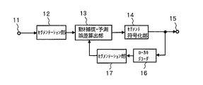
次に、本発明を実施するための最良の形態について説明する。図1は本発明になるセグメント単位画像符号化装置の一実施の形態のブロック図を示す。同図において、入力端子11にフレーム単位で入来した画像信号は、セグメンテーション部12に供給され、ここで後述するように画像信号がブロックに分割され、各ブロック毎の特徴量を計算された後、各特徴量が近い値を持つ隣接ブロック同士が統合されてセグメントが作成されると共に、統合されずに残された画像の輪郭を含むブロックが孤立ブロックとして分離される。セグメンテーション部12で作成された上記のセグメントと孤立ブロック及びその付加情報からなるセグメント情報は、フレーム画像信号と共に動き補償・予測誤差算出部13へ出力される。
Next, the best mode for carrying out the present invention will be described. FIG. 1 is a block diagram showing an embodiment of a segment unit image encoding apparatus according to the present invention. In the figure, an image signal that has entered the
動き補償・予測誤差算出部13は、セグメンテーション部12から入力されるセグメント情報とセグメンテーション部17から入力される1フレーム遅延画像信号のセグメント情報を基に予測画像信号を生成し、更にその予測画像信号を用いてセグメンテーション部12から入力されるフレーム画像信号との差分である予測誤差信号を生成し、その予測誤差信号とセグメント情報及び動きベクトルをセグメント符号化器14へ出力する。
The motion compensation / prediction
なお、上記の動きベクトルは動き補償・予測誤差算出部13において公知の方法で生成され、その生成の方法は問わないが、例えば、従来のブロック単位処理を行うMPEG方式のようにして求められる。すなわち、MPEG方式では、入力フレーム画像信号の任意の位置にある画素をブロック単位で切り出し、符号化するブロックの画素と輝度値の絶対値誤差の和が最小を与える入力フレーム画像信号の切り出し位置を1画素ずつずらしながら探索し、入力フレーム画像信号の中で前記絶対値誤差の和が最小になる位置と、符号化対象フレームの中の符号化するブロックの位置の水平方向の差と垂直方向の差がベクトルとして求められる。
The motion vector is generated by the motion compensation / prediction
これと同様に、動き補償・予測誤差算出部13においても、入力フレーム画像中を1画素ずつずらしながらセグメント形状に画素を切り出し、輝度値の絶対値誤差の和が最小になる位置を探索することで動きベクトルが求められる。
Similarly, the motion compensation / prediction
セグメント符号化部14は、動き補償・予測誤差算出部13から入力される各種情報を符号化し、出力端子15より符号化データとして外部に出力すると共に、ローカルデコーダ16へも出力する。ローカルデコーダ16では、セグメント符号化器14から入力される符号化データを基に画像を再合成し、次フレームの予測画像作成のためにセグメンテーション部17へ1フレーム遅延画像信号を出力する。
The
上記の1フレーム遅延画像信号はセグメンテーション部17で、セグメンテーション部12と同様の操作によりセグメンテーションを行い、動き補償・予測誤差算出部13へセグメンテーションされた1フレーム遅延画像信号を出力する。
The 1-frame delayed image signal is segmented by the
図1の実施の形態では、セグメンテーション部12、17以外は従来と同じ技術を流用できるので詳細な説明は省略し、本発明の特徴であるセグメンテーション部12、17について以下で詳述する。また、図1の構成はセグメント単位で動画像を符号化するシステムの一例であって、本発明の主たる目的であるセグメント単位画像符号化装置及びプログラムを制限するものではない。
In the embodiment of FIG. 1, the same technology as in the prior art can be used except for the
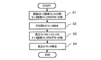
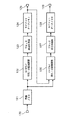
次に、セグメンテーション部12及び17の構成及び動作について説明する。ここで、セグメンテーション部12及び17は同一構成であるので、代表してセグメンテーション部12の構成及び動作について、図2のフローチャートと、図3のセグメンテーション部の一実施の形態のブロック図とを併せ参照して説明する。
Next, the configuration and operation of the
図1のセグメンテーション部12に入力される画像信号の水平及び垂直の各画素数は8の倍数であるとすると、図2のステップS1で入力画像信号を水平・垂直8×8画素のブロックに分割し、各8×8画素ブロックの画素値平均と画素値分散を求める。このステップS1での動作は、図3の入力端子120、画像メモリ121及び8×8ブロック平均・分散演算器122により実現される。
If the number of horizontal and vertical pixels of the image signal input to the
まず、図3の入力端子120(図1の入力端子11に相当)から入力される1フレーム分の画像信号が、画像メモリ121に蓄積される。画像メモリ121に蓄積された1フレーム分の画像信号は、後述する8×8ブロック平均・分散演算器122と4×4ブロック平均・分散演算器126へそれぞれ出力される。
First, an image signal for one frame input from the
次に、8×8ブロック平均・分散減算器122の動作を説明する。ここで、図4は、画像メモリ121に蓄積された画像信号を8×8画素のブロックに分割する例を示している。図4は画像信号の画素配列の一部を表現しており、黒丸は輝度(以後Yと表記する)と2つの色差(以後U,Vと表記する)の値を持つ画素を示している。
Next, the operation of the 8 × 8 block average /
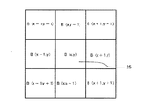
図4中のブロック枠21のように、画面全体が水平・垂直8×8画素のブロックで均等に分割される。各ブロックは、水平位置をx,垂直位置をyとしてB(x,y)により識別し、画面左上のブロック枠21をB(0,0)、ブロック枠22をB(1,0)、ブロック枠23をB(0,1)として順次番号をつける。
Like the
更に、水平・垂直8×8画素に分割された各ブロックの画素値Y,U,Vを画像メモリ121より読み出して8×8ブロック平均・分散演算器122で、各ブロック毎にY,U,Vそれぞれのブロック内平均とブロック内分散が計算される。8×8ブロック平均・分散演算器122で求められたブロックB(x,y)のY、U,Vの平均をそれぞれYa(x,y),Ua(x,y),Va(x,y)とし、分散をYd(x、y),Ud(x,y),Vd(x,y)で表現する。
Further, the pixel values Y, U, and V of each block divided into horizontal and vertical 8 × 8 pixels are read from the
以上の処理に続いて、図2のステップS1で求めたブロック内平均と分散を利用して、ステップS2において平坦部の大ブロックを統合するブロック統合処理によりセグメントを作成する。このステップS2での動作は、図3のブロック統合処理器123及びセグメントデータメモリ124により実現される。以下では、輝度値平均Ya(x,y)と輝度値分散Yd(x,y)のみで統合処理を行う例を示すが、Y,U,Vそれぞれの平均、分散を組み合わせて統合処理を行うことも当然可能である。
Subsequent to the above processing, using the block average and variance obtained in step S1 of FIG. 2, a segment is created by block integration processing in which the large blocks of the flat portion are integrated in step S2. The operation in step S2 is realized by the
図5はブロック25のB(x,y)を中心としてB(x,y)の統合対象となる周囲の8ブロックを示している。ブロックの統合は、中心ブロック25に対して8つの周辺ブロックを1つずつ後述する判定式に基づき統合の有無を決定して行く。
FIG. 5 shows 8 blocks around which B (x, y) is integrated, with B (x, y) in
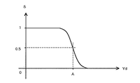
判定式は、ブロック25の輝度値平均をYa、輝度値分散をYdとし、ブロック25の周辺ブロックの輝度値平均をYa’としたとき数1の(1)式及び数2の(2)式で表される。そして、この(1)式に示すZ1が正値となる周辺ブロックをブロック25と統合する。
The determination formula is expressed by Equation (1) in
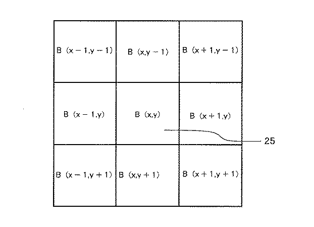
次に、(1)式の動作を説明する。δ値が零の時には、(1)式のZ1値は正値をとることはないのでブロックの統合は行われない。すなわち、中心ブロック25の輝度値分散Ydが規定値以上に大きい場合には、周囲のブロックの状態に関係なくブロック統合は行われない。
Next, the operation of equation (1) will be described. When the δ value is zero, the Z 1 value in the equation (1) does not take a positive value, so that block integration is not performed. That is, when the luminance value variance Yd of the
これに対し、中心ブロック25の輝度値分散Ydが規定値よりも小さい場合には、分散Ydの大きさに応じて中心ブロック25の輝度値平均Yaと周辺ブロックの輝度値平均Ya’の自乗誤差の許容範囲が可変されるように定数Cを選択する。これは、特徴量である輝度値分散Ydが小さい平担な画像成分を持つブロック同士が隣接している場合ほど、統合され易いことを意味している。以上の操作を中心ブロック25の周辺の8ブロックに対して順次行う。更に、中心ブロック25の位置をずらしながら同様の判定(検査)を行い、全てのブロックを検査する。
On the other hand, when the luminance value variance Yd of the
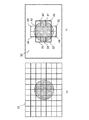
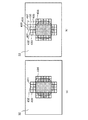
これにより、例えば、図7(a)の画像31のように円形の物体が中心にある画像を、直線で示される境界を持つ8×8画素のブロック単位に分割し、その後上記のブロック統合処理を行った結果は、図7(b)に示すようになる。図7(b)では、ブロック統合によりセグメント32と33が生成され、中心にある円形画像の周辺ブロック34〜43が輝度分散が大きな値になる輝度エッジを含むために孤立ブロックとして統合されずに残る。
Thereby, for example, an image having a circular object at the center like the
図3に戻って説明するに、ブロック統合処理器123で求められた上記のセグメントの形状情報及び孤立ブロック情報は、セグメントデータメモリ124に出力されて蓄積される。セグメントデータメモリ124に蓄積されたセグメント形状情報及び孤立ブロック情報は、出力端子125から出力される。
Returning to FIG. 3, the segment shape information and the isolated block information obtained by the
更に、図2のステップS3では、前記ステップS2で統合されずに残された孤立ブロック、例えば図7(b)に示した各々水平・垂直8×8画素のブロック34〜43を水平・垂直4×4画素の4つの小ブロックに分割し、各4×4画素ブロックの画素値平均と画素値分散を求める。このステップS3に相当する処理は、図3の4×4ブロック平均・分散演算器126で実現される。
Further, in step S3 of FIG. 2, the isolated blocks left unintegrated in step S2, for example, the
4×4ブロック平均・分散演算器126は、セグメントデータメモリ124より出力される孤立ブロック情報、例えば図8(a)の水平・垂直8×8画素の孤立ブロック情報を得て、図8(b)に示すような水平・垂直4×4画素の小ブロックに分割する。さらに、前記4×4画素ブロックの位置情報を基に、図3の4×4ブロック平均・分散演算器126は画像メモリ121から入力される画素値を用いて各4×4画素ブロックの画素値平均と画素値分散を求める。
The 4 × 4 block average /
以上の処理に続けて、前記各4×4画素ブロックは、図2のステップS4で孤立小ブロックの周辺セグメントとの統合処理が行われ、セグメント形状情報及び孤立ブロック情報が得られる。このステップS4での動作は、図3のブロック統合処理器127及びセグメントデータメモリ128により実現される。
Subsequent to the above processing, each 4 × 4 pixel block is integrated with the surrounding segments of the isolated small block in step S4 of FIG. 2 to obtain segment shape information and isolated block information. The operation in step S4 is realized by the
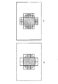
例えば、図7(b)に示した孤立ブロック43は、図9(a)に示すように、水平・垂直4×4画素の4つの小ブロック431、432、433及び434に分割されるが、このうちの小ブロック431の統合処理では、周囲にある小ブロック432〜434の他に、図9(b)に示すように、周囲の小ブロック435〜439をセグメント32から統合判定時に限って切り取る。
For example, the
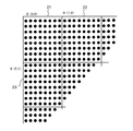
また、後述する判定式で小ブロック431に対する周辺の小ブロック432〜439との統合判定を行うが、周辺の小ブロック435〜439が中心の小ブロック431に統合されると判定された場合には、小ブロック431は小ブロック431を含むセグメント32に統合される。小ブロックの統合判定は数3に示す(3)式のZ2が正値のときに統合される。
In addition, the determination of the integration of the
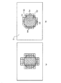
例えば、図10(a)の各小ブロックと周辺の小ブロックとを(3)式の判定式により統合した結果が図10(b)である。図10(b)の例では、2つのセグメント51及び52と円形の画像53の周辺を囲む20個の小ブロック54が生成される。
For example, FIG. 10B shows the result of integrating the small blocks in FIG. 10A and the surrounding small blocks using the determination formula (3). In the example of FIG. 10B, 20
図3のブロック統合処理器127で求められたセグメント形状情報及び孤立ブロック情報が、セグメントデータメモリ128に出力され蓄積される。セグメントデータメモリ128に蓄積されたセグメント形状情報及び孤立ブロック情報は、出力端子129から出力される。
The segment shape information and isolated block information obtained by the
以上の処理により、図1のセグメンテーション部12より生成されたセグメント形状情報と孤立小ブロックの情報が出力され、図1の動き補償・予測誤差算出部13へ供給される。次に、動き補償・予測誤差算出部13での動作の一例を図11及び図12により説明する。図11(a)に示す円形画像61は1フレーム前の画像で、図11(b)に示す画像62が現在の画像であるとする。
Through the above processing, the segment shape information and isolated small block information generated by the
図11(a)の円形画像61は撮影しているカメラから遠ざかる方向へ移動しており、画像62は遠ざかることにより大きさが小さくなる様子を示している。図11(b)の破線63は、図11(a)の時点での円形画像61の位置及び大きさを示している。従って、画像の輪郭に対して正確なセグメンテーショシを行う従来方式の場合には、破線63の大きさのセグメントが図11(b)に貼り付けられることになる。
The
これに対して、本実施の形態によれば、図12(a)に示すセグメント71が図12(b)に示す破線72の位置に貼り付けられる。ここで、破線72は図11(b)の遠ざかった画像62の位置と大きさを示しており、破線72の形を復元することが、子測誤差の少ない効率の良い符号化となる。本実施の形態によれば、図12(a)のセグメント71のエッジを含む周囲の孤立ブロックが破線72に沿うように上書きされ、図12(c)に示すような合成画像73が生成されるので、予測誤差の少ない効率の良い符号化ができる。
On the other hand, according to the present embodiment, the
この結果、図1の動き補償・予測誤差算出部13から生成された予測画像と原画像との誤差、セグメント情報、及び動きベクトルがセグメント符号化器14に入力され、セグメント符号化器14でエントロピー符号化などによる符号化されたデータが出力端子15より出力される。
As a result, the error, segment information, and motion vector between the prediction image and the original image generated from the motion compensation / prediction
なお、本発明は、上記した装置の機能をコンピュータに実現させるためのプログラムを含むものである。このプログラムは、記録媒体から読みとられてコンピュータに取り込まれてもよいし、通信ネットワークを介して伝送されてコンピュータに取り込まれてもよい。 The present invention includes a program for causing a computer to realize the functions of the apparatus described above. This program may be read from a recording medium and loaded into a computer, or may be transmitted via a communication network and loaded into a computer.
なお、本発明は以上の実施の形態に限定されるものではなく、例えば、上記の実施の形態では、輝度値平均Ya(x,y)と輝度値分散Yd(x,y)のみをブロック特徴量として統合処理を行う例を示したが、U,Vなどの色差信号の色差値平均と色差分散のみをブロック特徴量として統合処理を行うことも可能であり、更には輝度値平均、色差値平均、輝度値分散及び色差分散の全てを併用してブロック特徴量として統合処理を行うことも可能である。 The present invention is not limited to the above embodiment. For example, in the above embodiment, only the luminance value average Ya (x, y) and the luminance value variance Yd (x, y) are block features. Although an example of performing the integration process as a quantity has been shown, it is also possible to perform the integration process using only the color difference value average and the color difference variance of the color difference signals such as U and V as block feature quantities, and further, the luminance value average and color difference value It is also possible to perform integration processing as a block feature amount by using all of average, luminance value dispersion, and color difference dispersion.
11、120 入力端子
12、17 セグメンテーション部
13 動き補償・予測誤差算出部
14 セグメント符号化器
15、125、129 出力端子
16 ローカルデコーダ
121 画像メモリ
122 8×8ブロック平均・分散演算器
123、127 ブロック統合処理器
124、128 セグメントデータメモリ
126 4×4ブロック平均・分散演算器
DESCRIPTION OF
Claims (4)
前記供給される画像信号の2次元画像を第1の形状サイズのブロックの単位で分割する第1の分割手段と、
前記第1の分割手段により分割された前記ブロック内の画素が持つ輝度値及び色差値の少なくとも一方の平均値と分散値の組み合わせをブロック特徴量として、各ブロック毎に算出する第1の算出手段と、
前記ブロック特徴量が規定値より大きな値を持つブロックは孤立ブロックとして残し、前記ブロック特徴量が前記規定値以下の値を持つブロックのうち、前記ブロック特徴量が近似した値を持つ隣接ブロック同士を統合してセグメントとして作成する第1のセグメント作成手段と、
前記第1のセグメント作成手段から出力される信号を入力として受け、前記セグメント単位及び前記孤立ブロック単位に所定の符号化を行って符号化データを出力する符号化手段と
を有することを特徴とするセグメント単位画像符号化装置。 A segment unit image encoding apparatus that divides a two-dimensional image of a supplied image signal into a plurality of blocks and encodes the blocks in units of blocks,
First dividing means for dividing the two-dimensional image of the supplied image signal in units of blocks of a first shape size;
First calculation means for calculating, for each block, a combination of at least one of an average value and a variance value of luminance values and color difference values of pixels in the block divided by the first division means as a block feature amount When,
A block having a block feature value larger than a specified value is left as an isolated block, and among blocks having a block feature value equal to or less than the specified value, adjacent blocks having values approximate to the block feature value are detected. First segment creation means for creating a segment by integrating;
Encoding means for receiving a signal output from the first segment creation means as input, performing predetermined encoding on the segment unit and the isolated block unit, and outputting encoded data. Segment unit image encoding apparatus.
前記第2の分割手段により分割された前記小ブロック内の画素が持つ輝度値及び色差値の少なくとも一方の平均値と分散値の組み合わせをブロック特徴量として、各小ブロック毎に算出する第2の算出手段と、
前記第2の算出手段により算出された前記ブロック特徴量が規定値より大きな値を持つ小ブロックは孤立小ブロックとして残し、前記ブロック特徴量が前記規定値以下の値を持つ小ブロックのうち、前記ブロック特徴量が近似した値を持つ隣接する小ブロック又は前記セグメントと統合して新たなセグメントを作成する第2のセグメント作成手段と
を更に有し、前記符号化手段は、前記第2のセグメント作成手段から出力される信号を入力として受け、前記新たなセグメント単位及び前記孤立小ブロック単位に所定の符号化を行って符号化データを出力することを特徴とする請求項1記載のセグメント単位画像符号化装置。 Second dividing means for dividing the isolated block output from the first segment creating means in units of small blocks having a second shape size smaller than the first shape size;
A second feature of calculating for each small block a block feature value that is a combination of an average value and a variance value of at least one of a luminance value and a color difference value of pixels in the small block divided by the second dividing means; A calculation means;
The small block having the block feature value calculated by the second calculation means having a value larger than a specified value is left as an isolated small block, and among the small blocks having the block feature value having a value equal to or less than the specified value, And a second segment creating means for creating a new segment by integrating with adjacent small blocks having the approximate value of block feature or the segment, and the encoding means comprises the second segment creating 2. The segment unit image code according to claim 1, wherein a signal output from the means is received as input, and the new segment unit and the isolated small block unit are subjected to predetermined encoding to output encoded data. Device.
前記コンピュータを、
供給される画像信号の2次元画像を第1の形状サイズのブロックの単位で分割する第1の分割手段と、
前記第1の分割手段により分割された前記ブロック内の画素が持つ輝度値及び色差値の少なくとも一方の平均値と分散値の組み合わせをブロック特徴量として、各ブロック毎に算出する第1の算出手段と、
前記ブロック特徴量が規定値より大きな値を持つブロックは孤立ブロックとして残し、前記ブロック特徴量が前記規定値以下の値を持つブロックのうち、前記ブロック特徴量が近似した値を持つ隣接ブロック同士を統合してセグメントとして作成する第1のセグメント作成手段と、
前記第1のセグメント作成手段から出力される信号を入力として受け、前記セグメント単位及び前記孤立ブロック単位に所定の符号化を行って符号化データを出力する符号化手段として機能させることを特徴とするセグメント単位画像符号化プログラム。 A segment unit image encoding program for operating a computer to divide a two-dimensional image of a supplied image signal into a plurality of blocks and encode the block unit,
The computer,
First dividing means for dividing a two-dimensional image of the supplied image signal in units of blocks of a first shape size;
First calculation means for calculating, for each block, a combination of at least one of an average value and a variance value of luminance values and color difference values of pixels in the block divided by the first division means as a block feature amount When,
A block having a block feature value larger than a specified value is left as an isolated block, and among blocks having a block feature value equal to or less than the specified value, adjacent blocks having values approximate to the block feature value are detected. First segment creation means for creating a segment by integrating;
Receiving a signal output from the first segment creation means as an input, and performing a predetermined encoding on the segment unit and the isolated block unit to function as an encoding means for outputting encoded data. Segment unit image encoding program.
前記第1のセグメント作成手段から出力される前記孤立ブロックを、前記第1の形状サイズより小である第2の形状サイズの小ブロックの単位で分割する第2の分割手段と、
前記第2の分割手段により分割された前記小ブロック内の画素が持つ輝度値及び色差値の少なくとも一方の平均値と分散値の組み合わせをブロック特徴量として、各小ブロック毎に算出する第2の算出手段と、
前記第2の算出手段により算出された前記ブロック特徴量が規定値より大きな値を持つ小ブロックは孤立小ブロックとして残し、前記ブロック特徴量が前記規定値以下の値を持つ小ブロックのうち、前記ブロック特徴量が近似した値を持つ隣接する小ブロック又は前記セグメントと統合して新たなセグメントを作成する第2のセグメント作成手段として更に機能させ、前記符号化手段を、前記第2のセグメント作成手段から出力される信号を入力として受け、前記新たなセグメント単位及び前記孤立小ブロック単位に所定の符号化を行って符号化データを出力するように機能させることを特徴とする請求項1記載のセグメント単位画像符号化プログラム。
The computer,
Second dividing means for dividing the isolated block output from the first segment creating means in units of small blocks having a second shape size smaller than the first shape size;
A second feature of calculating for each small block a block feature value that is a combination of an average value and a variance value of at least one of a luminance value and a color difference value of pixels in the small block divided by the second dividing means; A calculation means;
The small block having the block feature value calculated by the second calculation means having a value larger than a specified value is left as an isolated small block, and among the small blocks having the block feature value having a value equal to or less than the specified value, Further functioning as a second segment creation means for creating a new segment by integrating with adjacent small blocks having the approximate value of the block feature value or the segment, and the encoding means, the second segment creation means 2. The segment according to claim 1, which receives a signal output from an input as a input and performs a predetermined encoding on the new segment unit and the isolated small block unit to output encoded data. Unit image encoding program.
Priority Applications (1)
| Application Number | Priority Date | Filing Date | Title |
|---|---|---|---|
| JP2003356693A JP4100321B2 (en) | 2003-10-16 | 2003-10-16 | Segment unit image encoding apparatus and segment unit image encoding program |
Applications Claiming Priority (1)
| Application Number | Priority Date | Filing Date | Title |
|---|---|---|---|
| JP2003356693A JP4100321B2 (en) | 2003-10-16 | 2003-10-16 | Segment unit image encoding apparatus and segment unit image encoding program |
Publications (2)
| Publication Number | Publication Date |
|---|---|
| JP2005123895A JP2005123895A (en) | 2005-05-12 |
| JP4100321B2 true JP4100321B2 (en) | 2008-06-11 |
Family
ID=34613856
Family Applications (1)
| Application Number | Title | Priority Date | Filing Date |
|---|---|---|---|
| JP2003356693A Expired - Fee Related JP4100321B2 (en) | 2003-10-16 | 2003-10-16 | Segment unit image encoding apparatus and segment unit image encoding program |
Country Status (1)
| Country | Link |
|---|---|
| JP (1) | JP4100321B2 (en) |
-
2003
- 2003-10-16 JP JP2003356693A patent/JP4100321B2/en not_active Expired - Fee Related
Also Published As
| Publication number | Publication date |
|---|---|
| JP2005123895A (en) | 2005-05-12 |
Similar Documents
| Publication | Publication Date | Title |
|---|---|---|
| US7986810B2 (en) | Mesh based frame processing and applications | |
| US8351685B2 (en) | Device and method for estimating depth map, and method for generating intermediate image and method for encoding multi-view video using the same | |
| US8098733B2 (en) | Multi-directional motion estimation using parallel processors and pre-computed search-strategy offset tables | |
| JP5521202B2 (en) | Multi-view image encoding method, multi-view image decoding method, multi-view image encoding device, multi-view image decoding device, multi-view image encoding program, and multi-view image decoding program | |
| EP1639829B1 (en) | Optical flow estimation method | |
| US6418168B1 (en) | Motion vector detection apparatus, method of the same, and image processing apparatus | |
| CN116248875A (en) | Spherical projection motion estimation/compensation and mode decision | |
| CN110830802A (en) | Video compression based on machine learning | |
| JP2009147807A (en) | Image processing apparatus | |
| JP2003018604A (en) | Image signal encoding method, device thereof and recording medium | |
| JP2007124408A (en) | Motion vector detector and motion vector detecting method | |
| JPH0898183A (en) | Method and device for two-way prediction | |
| JP2000224593A (en) | Method and device for interpolating frame and recording medium recording the method | |
| JP2003032688A (en) | Separation method of foreground and background regions for moving image, and moving image coding method by conditional pixel replenishment by using this method | |
| US20070047643A1 (en) | Video data compression | |
| JP2010258576A (en) | Scene change detector, and video recorder | |
| JPH089379A (en) | Motion vector detection method | |
| JP4523024B2 (en) | Image coding apparatus and image coding method | |
| JP3175914B2 (en) | Image encoding method and image encoding device | |
| JP4100321B2 (en) | Segment unit image encoding apparatus and segment unit image encoding program | |
| JP2022103284A (en) | Video encoder, video decoder, and their program | |
| JP2008141616A (en) | Motion vector calculating apparatus, method and program, moving image compressing and recording device, and imaging apparatus | |
| JP4671696B2 (en) | Motion vector detection device | |
| JP2004096557A (en) | Image processor and image processing method | |
| JPH08242454A (en) | Method for detecting global motion parameter |
Legal Events
| Date | Code | Title | Description |
|---|---|---|---|
| A621 | Written request for application examination |
Free format text: JAPANESE INTERMEDIATE CODE: A621 Effective date: 20060331 |
|
| A977 | Report on retrieval |
Free format text: JAPANESE INTERMEDIATE CODE: A971007 Effective date: 20080219 |
|
| TRDD | Decision of grant or rejection written | ||
| A01 | Written decision to grant a patent or to grant a registration (utility model) |
Free format text: JAPANESE INTERMEDIATE CODE: A01 Effective date: 20080226 |
|
| A61 | First payment of annual fees (during grant procedure) |
Free format text: JAPANESE INTERMEDIATE CODE: A61 Effective date: 20080310 |
|
| FPAY | Renewal fee payment (event date is renewal date of database) |
Free format text: PAYMENT UNTIL: 20110328 Year of fee payment: 3 |
|
| FPAY | Renewal fee payment (event date is renewal date of database) |
Free format text: PAYMENT UNTIL: 20120328 Year of fee payment: 4 |
|
| LAPS | Cancellation because of no payment of annual fees |