EP1639829B1 - Optical flow estimation method - Google Patents
Optical flow estimation method Download PDFInfo
- Publication number
- EP1639829B1 EP1639829B1 EP04766110.3A EP04766110A EP1639829B1 EP 1639829 B1 EP1639829 B1 EP 1639829B1 EP 04766110 A EP04766110 A EP 04766110A EP 1639829 B1 EP1639829 B1 EP 1639829B1
- Authority
- EP
- European Patent Office
- Prior art keywords
- data
- data blocks
- frame data
- blocks
- encoded image
- Prior art date
- Legal status (The legal status is an assumption and is not a legal conclusion. Google has not performed a legal analysis and makes no representation as to the accuracy of the status listed.)
- Expired - Lifetime
Links
- 238000000034 method Methods 0.000 title claims description 36
- 230000003287 optical effect Effects 0.000 title claims description 33
- 230000033001 locomotion Effects 0.000 claims description 134
- 239000013598 vector Substances 0.000 claims description 65
- 238000000605 extraction Methods 0.000 claims description 4
- 238000001914 filtration Methods 0.000 claims description 3
- 230000009466 transformation Effects 0.000 claims description 3
- 238000009795 derivation Methods 0.000 claims 3
- 230000000694 effects Effects 0.000 description 10
- 239000011159 matrix material Substances 0.000 description 7
- 230000006835 compression Effects 0.000 description 5
- 238000007906 compression Methods 0.000 description 5
- 238000012545 processing Methods 0.000 description 5
- 230000011218 segmentation Effects 0.000 description 5
- 238000012935 Averaging Methods 0.000 description 4
- 238000010586 diagram Methods 0.000 description 4
- 230000002123 temporal effect Effects 0.000 description 4
- 238000001514 detection method Methods 0.000 description 3
- 238000005286 illumination Methods 0.000 description 3
- 238000013139 quantization Methods 0.000 description 3
- 230000009467 reduction Effects 0.000 description 3
- 230000006837 decompression Effects 0.000 description 2
- 238000013519 translation Methods 0.000 description 2
- 230000003044 adaptive effect Effects 0.000 description 1
- 238000013459 approach Methods 0.000 description 1
- 238000004590 computer program Methods 0.000 description 1
- 230000001419 dependent effect Effects 0.000 description 1
- 238000009499 grossing Methods 0.000 description 1
- 238000003384 imaging method Methods 0.000 description 1
- 230000006872 improvement Effects 0.000 description 1
- 238000012986 modification Methods 0.000 description 1
- 230000004048 modification Effects 0.000 description 1
- 238000005457 optimization Methods 0.000 description 1
- 230000008569 process Effects 0.000 description 1
- 230000004044 response Effects 0.000 description 1
- 230000003068 static effect Effects 0.000 description 1
- 230000000153 supplemental effect Effects 0.000 description 1
- 238000012360 testing method Methods 0.000 description 1
- 238000012800 visualization Methods 0.000 description 1
Images


Classifications
-
- H—ELECTRICITY
- H04—ELECTRIC COMMUNICATION TECHNIQUE
- H04N—PICTORIAL COMMUNICATION, e.g. TELEVISION
- H04N19/00—Methods or arrangements for coding, decoding, compressing or decompressing digital video signals
- H04N19/50—Methods or arrangements for coding, decoding, compressing or decompressing digital video signals using predictive coding
- H04N19/503—Methods or arrangements for coding, decoding, compressing or decompressing digital video signals using predictive coding involving temporal prediction
- H04N19/51—Motion estimation or motion compensation
- H04N19/513—Processing of motion vectors
- H04N19/521—Processing of motion vectors for estimating the reliability of the determined motion vectors or motion vector field, e.g. for smoothing the motion vector field or for correcting motion vectors
-
- G—PHYSICS
- G06—COMPUTING; CALCULATING OR COUNTING
- G06T—IMAGE DATA PROCESSING OR GENERATION, IN GENERAL
- G06T7/00—Image analysis
- G06T7/20—Analysis of motion
- G06T7/269—Analysis of motion using gradient-based methods
-
- H—ELECTRICITY
- H04—ELECTRIC COMMUNICATION TECHNIQUE
- H04N—PICTORIAL COMMUNICATION, e.g. TELEVISION
- H04N19/00—Methods or arrangements for coding, decoding, compressing or decompressing digital video signals
- H04N19/48—Methods or arrangements for coding, decoding, compressing or decompressing digital video signals using compressed domain processing techniques other than decoding, e.g. modification of transform coefficients, variable length coding [VLC] data or run-length data
-
- H—ELECTRICITY
- H04—ELECTRIC COMMUNICATION TECHNIQUE
- H04N—PICTORIAL COMMUNICATION, e.g. TELEVISION
- H04N19/00—Methods or arrangements for coding, decoding, compressing or decompressing digital video signals
- H04N19/50—Methods or arrangements for coding, decoding, compressing or decompressing digital video signals using predictive coding
- H04N19/503—Methods or arrangements for coding, decoding, compressing or decompressing digital video signals using predictive coding involving temporal prediction
- H04N19/51—Motion estimation or motion compensation
- H04N19/513—Processing of motion vectors
Definitions
- This invention relates to optical flow estimation, and, in particular, optical flow estimation in a compressed video data stream.
- This velocity is a two dimensional approximation of the real scene movement in the image plane that may be termed real velocity.
- the gradient constraint equation requires additional constraints for resolution. Horn and Schunck (above) use a global smoothness term to solve this problem, while Lucas and Kanade ("An Iterative Image Registration Technique with an Application to Stereo Vision", Proc. Of the Imaging Understanding Workshop 1981 pp 121-130 ) use a weighted least-squares fit of local first-order constraints assuming that image gradient is almost constant for local neighbourhoods.
- the Lucas Kanade method generates matrix eigenvalues, the magnitude of the eigenvalues being directly related to the strength of edges in the image and the eigenvalues being used to create a confidence map of optical flow accuracy.
- a confidence map is a set of data which stores the confidence, or variance, at each pixel for the accuracy of the optical flow field.
- US Patent No, 6,456,731 discloses an optical flow estimation method which incorporates a known hierarchically-structured Lucas Kanade method for interpolating optical flow between regions having different confidence values.
- MPEG-2 video encoding allows high-quality video to be encoded, transmitted and stored and is achieved by eliminating spatial and temporal redundancy that typically occurs in video streams.
- each macroblock is divided into four 8x8 luminance blocks and eight, four or two chrominance blocks according to a selected chroma key.
- a discrete-cosine transform (DCT), an invertible discrete orthogonal transformation (see “ Generic Coding of Moving Pictures and Associated Audio", Recommendation H.262, ISO/IEC 13818-2, Committee Draft MPEG-2 ), is applied to each 8x8 luminance block giving a matrix that is mostly composed of zeros (high-frequency power) and a small number of non-zero values.
- the quantization step that follows effectively controls compression ratios by discarding more or less information according to the value of the quantization scale. Zig-zag and Huffman coding exploit the resulting high-number of zero values and compress the image data.
- Temporal redundancy is quite severe in video since consecutive images are very similar. To achieve even better compression each macroblock is compared not to its direct spatial equivalent in a previous image but to a translated version of it (to compensate for movement in the scene) that is found using a block-matching algorithm.
- the translation details are stored in a motion vector that refers to either a previous image or a following image depending on the picture type.
- MPEG-2 encoding defines three kinds of image data: intra-coded frame data (I pictures) with only spatial compression (no motion vectors), predicted frame data (P pictures) and bi-directionally interpolated frame data (B pictures) with motion estimation.
- I pictures intra-coded frame data
- P pictures predicted frame data
- B pictures bi-directionally interpolated frame data
- I pictures only have intra-coded macroblocks (macroblocks without motion estimation) because they are coded without reference to other pictures.
- P and B pictures can also include inter-coded macroblocks (macroblocks where only the difference to the original macroblock designated by the motion vector is encoded).
- P pictures are coded more efficiently using motion compensated prediction from a past I or P picture and are generally used as a reference for future prediction.
- B pictures provide the highest degree of compression but require both past and future reference pictures for motion compensation; they are never used as references for prediction.
- Figure 1 illustrates the typical picture sequence of an MPEG-2 compressed video data stream.
- the organisation of the three picture types, I, B and P pictures, in a video stream is flexible, the choice being left to the encoder and being dependent on the requirements of the application.
- the pictures are in the sequence IBBPBBP, and the arrows represent the direction in which pictures are estimated.
- I pictures are used to predict B and P pictures.
- P pictures are used to predict prior and following B pictures.
- B pictures are not used as references for other pictures.
- US 6157396 discloses a system for improving the quality of digital video using a multitude of techniques and focussing on MPEG-2 compressed video data.
- the system aims to enhance standard compressed MPEG-2 decoding by using a number of additional processes, including retaining groups of pictures (GOP) and the motion vector information, to aid post decompression filtering in the image reconstruction (IR) and digital output processor (DOP).
- the system decompresses the image but retains the motion vectors for later use in the DOP.
- Supplemental information such as a layered video stream, instructional cues and image key meta data, is used to enhance the quality of the decoded image through post decompression filtering.
- this system relies on decompression of the MPEG-2 compressed video data which is disadvantageous in that it tends to increase computational complexity and decrease processing speed.
- an optical flow estimation system according to claim 5.
- Lucas Kanade method of optical flow estimation involves direct processing of pixel information.
- the preferred embodiment of the present invention to be described below closely approximates the Lucas Kanade method but working in the compressed video data domain, using only quantities related to the compressed video data.
- a parallel between the Lucas Kanade method and that of the preferred embodiment is drawn in Figure 2 .
- Two tasks can be identified, namely the generation of a motion vector field with one vector per data macroblock and estimation of a confidence map for the motion vector field. Not every data macroblock has one motion vector. Some data macroblocks have none (intra-coded blocks) and some have two (interpolated blocks in B pictures). Therefore a basis is needed upon which a smooth motion field based on MPEG-2 motion vectors can be generated.
- the obtained motion vector field like the optical flow field, needs some sort of confidence measure for each vector to be meaningful. Areas of the motion vector field with strong edges exhibit better correlation with real motion than textureless ones.
- a DCT block is the set of 64 DCT coefficients which result from application of a DCT to a data macroblock.
- a DCT coefficient is the amplitude of a specific cosine basis function, while an AC coefficient is a DCT coefficient for which the frequency in one or both of the dimensions is non-zero.
- DCT coefficients of an intra-coded data macroblock have a measure of edge strength in the AC coefficients.
- the AC[1] and AC[8] coefficients within such a macroblock, illustrated in Figure 3 measure the strength and direction of an edge within the 8x8 luminance block, and, drawing a parallel to the eigenvalues of the Lucas Kanade method, it is possible to use these two coefficients to obtain a set of confidence measures for the MPEG-2 compressed video data stream.
- the AC[1] and AC[8] coefficients may be considered approximations to the average spatial gradients over a DCT data block.
- f ( x , y ) be the 8 ⁇ 8 image block
- F ( u , v ) be the block's DCT.
- a similar expression for spatial gradient f y ( x , y ) can also be obtained.
- w ( x , y ) is some spatial weighting function.
- a popular weighting function to choose is a Gaussian.
- the coefficients AC[1] and AC[8] approximate to the average spatial gradient within a block: AC 1 ⁇ - f x ⁇ AC 8 ⁇ - f y ⁇ .
- a strong eigenvalue signals a large image gradient, e.g. an edge, in this block and the associated eigenvector will be normal to the edge's direction. Only the magnitude of ⁇ 1 has been used as a confidence measure, but the difference between the direction of the motion vector and e 1 could also be analyzed.
- An MPEG-2 compressed video data stream has a variable number of DCT blocks for each macroblock that varies with the chroma quantization encoding parameter. Only the luminance DCT blocks are used in this embodiment, because there are always four per data macroblock (unlike the chrominance blocks that can have two, four or eight). Another reason is that the standard Lucas Kanade method only uses luminance values, so that, since the preferred embodiment attempts to approximate it, it should use only luminance as well.
- Figure 4 shows an example of a confidence map, generated from the AC[1] and AC[8] coefficients, of the form AC[1] 2 + AC[8] 2 , and its correlation with edge strength.
- FIG. 1 illustrates how an inter-coded macroblock (in this case from a P picture) relates to a corresponding I picture confidence map. Since motion vectors in MPEG-2 compressed video data have half-pixel accuracy, they rarely point to the top-left corner of a DCT data block, so that interpolation is required. The typical scenario will be that the new confidence is a weighted average of four DCT blocks.
- Figure 7 shows how DCT blocks may be used to estimate the confidence of an error block.
- Every confidence map update step involves interpolating new confidences and the confidence map is only reset on I pictures that occur every 12 pictures in a typical IBBPBBPBBPBB sequence. In practice, this problem is not that serious if adequate measures are taken.
- An obvious measure is that updates should be kept to a minimum in order to avoid excessive blurring of the confidence map. In fact, an update is only necessary when a vector is larger than half a DCT data block, if a vector is smaller than this there is a low probability that that edge has moved significantly. Also, since motion vectors of a P picture only refer to the previous I or P picture, there is a maximum of three update steps, making error propagation less serious. Confidence map updating in B pictures may depend on the magnitude of motion present in the compressed video data sequence.
- Step 1 corresponds to obtaining a frame header from the encoded image data, which, for an MPEG-2 data stream, will comprise information describing whether the frame is an I, B or P picture.
- Pictures used exclusively for reference purposes do not contain motion vector encoding, whereas predicted pictures contain motion vector information describing how to obtain the predicted picture from a reference picture.
- the encoded video data is MPEG-2 encoded data
- I pictures have no motion vector encoding, whereas both B and P pictures do incorporate motion vector encoding.
- the decision is therefore made on the basis of information extracted from the frame header.
- step 3 first frame data blocks not incorporating motion vector encoding are extracted.
- this step comprises extracting macroblocks of the I pictures yielding DCT coefficients.
- AC coefficients AC[1] and AC[8] are a subset of the DCT coefficients, and provide information on the strength and direction of edges in the real image.
- the encoded image data not containing motion vector encoding is used to generate a confidence map indicative of the edge strength within the image data and hence the accuracy of the motion field.
- the AC[1] and AC[8] coefficients are used to create the confidence map for MPEG-2 encoded data.
- step 5 If the decision made at step 2 is that the encoded image data does incorporate motion vector encoding then, at step 5, second frame data blocks incorporating motion vector encoding are extracted. In the case of MPEG-2 encoded data, this step comprises extracting macroblocks of the B and P pictures.
- the second frame data blocks are used to derive smooth motion field data blocks in which each data block has a single motion vector and the magnitudes of the motion vectors are normalised. This is achieved by application of a set of rules which compensate for not every macroblock having one motion vector or motion vectors of a normalised magnitude. As noted above, such rules remove the dependency on the specific format in which the image data is encoded.
- the confidence map data determined in step 4 above is updated at step 7 on the basis of the smooth motion field data blocks derived in step 6.
- the motion vectors relate regions of the first frame data blocks to regions of the second frame data blocks. This provides a function taking the confidence map from the first frame onto the second frame. Because the motion vectors typically do not exactly map a DCT block in an I image to a DCT block in a P or B image it is necessary to interpolate across the confidence map as depicted in Figure 6 .
- the new confidence map is a weighted average of the confidence values for the neighbouring 4 DCT blocks as shown in Figure 7 .
- Steps 4 and 7 thereby together provide an updated confidence map for the smoothed motion vectors, leading to an estimate of the high confidence optical flow within the image, as performed in step 8.
- the high confidence optical flow data can be spatially interpolated as performed in step 9.
- Magnitude and confidence map thresholding can be applied to remove the majority of the noisy vectors, removing glow effects of lights on shiny surfaces and shadows.
- Such data is somewhat sensitive to a fixed threshold and accordingly a motion segmentation algorithm using the motion estimation of the preferred embodiment could use more flexible decision methods (adaptive thresholding, multi-step thresholding, probabilistic models, etc.).
- a fixed threshold is sufficient, and accordingly the examples referred to below use this for simplicity of visualization of the results.
- Figures 8a and 8b show the effect of using confidence thresholding to remove illumination noise and increase the accuracy of the motion estimation.
- Figure 9 shows the majority of the illumination noise.
- Figures 10a and 10b show the noise reduction effect of the confidence map before and after thresholding respectively. Such noise can be dealt with by a subsequent motion segmentation algorithm.
- Figures 11a and 11b show the thresholded low-resolution motion field (16x16 blocks) in a scene with moving objects being shown before and after confidence thresholding in Figures 11a and 11b respectively.
- Motion fields generated according to the Lucas Kanade method provide dense motion maps in that a motion vector is provided for every pixel. This can be seen in Figure 12a where pixels with vectors pointing right are shown in white and vectors pointing left are show in grey for the sub-sampled Lucas Kanade motion field.
- Figure 12b shows the same scene, with the MPEG-2 smooth motion field.
- Figure 13a shows this Lucas Kanade motion field subsampled to the same resolution as the proposed scheme, and Figure 13b shows how successfully the smooth motion field of the present invention approximates it.
- Figures 14a and 14b show both motion fields corresponding to another situation (that depicted in Figure 5a ), these figures showing the subsampled Lucas Kanade and MPEG-2 smooth motion fields respectively. A close match may be observed between the Lucas Kanade motion field and that of the preferred embodiment of the present invention.
- Figures 15a and 15b An example of the blurring effect caused by the confidence map update step is shown in Figures 15a and 15b .
- the most severe case is presented (after three update steps) to show that, even with some blurring, the approximation is still quite accurate. Some definition is lost in the shape of the object, but most of the motion is still correct.
- Figure 15a shows the MPEG-2 smooth motion field
- Figure 15b the Lucas Kanade motion field.
- the approximation to the Lucas Kanade method of optical flow estimation provided by the preferred embodiment of the present invention is obtained at very low computational cost. All of the operations are simple and are applied to a small data set (44*30 macroblocks, 44*30*4 DCT blocks). This, allied with minimal MPEG-2 decoding, easily allows frame rates of over 25 images per second with unoptimised code. A rough comparison with Lucas Kanade method code shows that the algorithm of the preferred embodiment is approximately 50 times faster. With appropriate optimization, faster performance is possible. Given its low complexity, the method of the present invention may be implemented in a low cost real time optical flow estimator based around an inexpensive digital signal processing chipset.
- the present invention provides a method for estimating optical flow, particularly optical flow as estimated by the well-known Lucas Kanade method, using only compressed video data. It will be appreciated by the person skilled in the art that various modifications may be made to the above described embodiments without departing from the scope of the present invention.
- Lucas Kanade and present invention matrices can be approximately characterized as follows: M ⁇ ⁇ E f x f y ⁇ f x f y and M ⁇ ⁇ E f x E f y ⁇ E f x E f y respectively, where E ⁇ o ⁇ represents expectation over the image pixels and the scale difference in M ' has been ignored.
Landscapes
- Engineering & Computer Science (AREA)
- Multimedia (AREA)
- Signal Processing (AREA)
- Computer Vision & Pattern Recognition (AREA)
- Physics & Mathematics (AREA)
- General Physics & Mathematics (AREA)
- Theoretical Computer Science (AREA)
- Compression Or Coding Systems Of Tv Signals (AREA)
- Image Analysis (AREA)
Description
- This invention relates to optical flow estimation, and, in particular, optical flow estimation in a compressed video data stream.
- One of the problems of image processing lies in distinguishing foreground objects from background images in video data. Applications in areas as diverse as video processing, video compressing or machine vision rely on effective segmentation techniques to perform their desired tasks. Motion segmentation exploits the temporal correlation of consecutive video images and detects image regions with different motion. This two dimensional motion, usually called apparent motion or optical flow, needs to be recovered from image intensity and colour information in a video sequence.
- In general, depending on the target application, one can trade optimisation performance (accuracy) against computational load (efficiency). Some specific applications need very high efficiency due to real-time requirements and practical feasibility. Surveillance applications, such as a pedestrian detection system for underground train stations, are an example of a situation in which a controlled environment (fixed camera, controlled illumination) allied with cost requirements (large numbers of cameras and necessity of fast response times) is a good target for high efficiency algorithms. Such a system is likely to use one of the popular available video encoding standards that already use some form of motion estimation designed for compression purposes.
- Horn and Schunck, "Determining Optical Flow", in AL Memo 572, Massachusetts Institute of Technology, 1980 defines optical flow as "the distribution of apparent velocities of movement of brightness patterns in an image". This definition assumes that all changes in the image are caused by the translation of these brightness patterns, leading to the gradient constraint equation, involving spatial and temporal gradients and an optical flow velocity.
- This velocity is a two dimensional approximation of the real scene movement in the image plane that may be termed real velocity. The gradient constraint equation requires additional constraints for resolution. Horn and Schunck (above) use a global smoothness term to solve this problem, while Lucas and Kanade ("An Iterative Image Registration Technique with an Application to Stereo Vision", Proc. Of the Imaging Understanding Workshop 1981 pp 121-130) use a weighted least-squares fit of local first-order constraints assuming that image gradient is almost constant for local neighbourhoods. The Lucas Kanade method generates matrix eigenvalues, the magnitude of the eigenvalues being directly related to the strength of edges in the image and the eigenvalues being used to create a confidence map of optical flow accuracy.
- A confidence map is a set of data which stores the confidence, or variance, at each pixel for the accuracy of the optical flow field.
- Both of the above methods are called differential methods since they use the gradient constraint equation directly to estimate optical flow. The largest problem of such differential methods is that they cannot be applied to large motions because a good initial value is required.
-
US Patent No, 6,456,731 discloses an optical flow estimation method which incorporates a known hierarchically-structured Lucas Kanade method for interpolating optical flow between regions having different confidence values. - MPEG-2 video encoding allows high-quality video to be encoded, transmitted and stored and is achieved by eliminating spatial and temporal redundancy that typically occurs in video streams.
- In MPEG-2 encoding, the image is divided in 16x16 areas called macroblocks, and each macroblock is divided into four 8x8 luminance blocks and eight, four or two chrominance blocks according to a selected chroma key. A discrete-cosine transform (DCT), an invertible discrete orthogonal transformation (see "Generic Coding of Moving Pictures and Associated Audio", Recommendation H.262, ISO/IEC 13818-2, Committee Draft MPEG-2), is applied to each 8x8 luminance block giving a matrix that is mostly composed of zeros (high-frequency power) and a small number of non-zero values. The quantization step that follows effectively controls compression ratios by discarding more or less information according to the value of the quantization scale. Zig-zag and Huffman coding exploit the resulting high-number of zero values and compress the image data.
- Temporal redundancy is quite severe in video since consecutive images are very similar. To achieve even better compression each macroblock is compared not to its direct spatial equivalent in a previous image but to a translated version of it (to compensate for movement in the scene) that is found using a block-matching algorithm. The translation details are stored in a motion vector that refers to either a previous image or a following image depending on the picture type.
- MPEG-2 encoding defines three kinds of image data: intra-coded frame data (I pictures) with only spatial compression (no motion vectors), predicted frame data (P pictures) and bi-directionally interpolated frame data (B pictures) with motion estimation.
- I pictures only have intra-coded macroblocks (macroblocks without motion estimation) because they are coded without reference to other pictures. P and B pictures can also include inter-coded macroblocks (macroblocks where only the difference to the original macroblock designated by the motion vector is encoded). P pictures are coded more efficiently using motion compensated prediction from a past I or P picture and are generally used as a reference for future prediction. B pictures provide the highest degree of compression but require both past and future reference pictures for motion compensation; they are never used as references for prediction.
-
Figure 1 illustrates the typical picture sequence of an MPEG-2 compressed video data stream. The organisation of the three picture types, I, B and P pictures, in a video stream is flexible, the choice being left to the encoder and being dependent on the requirements of the application. In the particular example shown the pictures are in the sequence IBBPBBP, and the arrows represent the direction in which pictures are estimated. I pictures are used to predict B and P pictures. P pictures are used to predict prior and following B pictures. B pictures are not used as references for other pictures. - Wang et al, "A confidence measure based moving object extraction system built for compressed domain", IEEE International Symposium on Circuits and Systems, May 28-31, 2000, Geneva, Switzerland, discloses a moving object extraction system with a general framework and component designs and shows their effectiveness with two test sequences.
- Bo Shen and Ishwar K. Sethi, "Direct feature extraction from compressed images", PROCEEDINGS OF SPIE, STORAGE AND RETRIEVAL FOR STILL IMAGE AND discloses detecting edge strength and direction using the discrete cosine transform coefficients.
-
US 6157396 discloses a system for improving the quality of digital video using a multitude of techniques and focussing on MPEG-2 compressed video data. The system aims to enhance standard compressed MPEG-2 decoding by using a number of additional processes, including retaining groups of pictures (GOP) and the motion vector information, to aid post decompression filtering in the image reconstruction (IR) and digital output processor (DOP). The system decompresses the image but retains the motion vectors for later use in the DOP. Supplemental information, such as a layered video stream, instructional cues and image key meta data, is used to enhance the quality of the decoded image through post decompression filtering. However this system relies on decompression of the MPEG-2 compressed video data which is disadvantageous in that it tends to increase computational complexity and decrease processing speed. - It is an object of the present invention to provide fast, reasonably accurate two-dimensional motion estimation of a video scene for applications in which it is desired to avoid high computational costs and compressed digital video data is used.
It is a further object of the present invention to provide such motion estimation which closely approximates the Lucas-Kanade method of optical flow estimation, but working only with compressed video data. - According to a first aspect of the present invention there is provided an optical flow estimation method according to
claim 1. - According to a second aspect of the present invention there is provided an optical flow estimation system according to
claim 5. - According to a third aspect of the present invention there is provided computer readable recording medium according to claim 10.
- For a better understanding of the present invention and in order to show how the same may be carried into effect, a preferred embodiment of an optical flow estimation method in accordance with the present invention will now be described, by way of example, with reference to the accompanying drawings, in which:
-
Figure 1 illustrates a typical image sequence of an MPEG-2 encoded video data stream; -
Figure 2 is a diagram providing a comparison of the Lucas Kanade method of optical flow estimation with that of a preferred embodiment of the present invention; -
Figure 3 illustrates the structure of the AC[1] and AC[8] coefficients within a DCT block of the encoded video data stream; -
Figure 4 shows a confidence map; -
Figures 5a to 5d illustrate the steps for obtaining a smooth motion field in accordance with a preferred embodiment of the present invention; -
Figure 6 is a diagram illustrating the basis of a confidence map update step in such an embodiment; -
Figure 7 is a diagram illustrating a typical scenario where the new confidence map is a weighted average of the four associated DCT blocks in the I image. -
Figures 8a and 8b illustrate the effects of thresholding on a scene with no real motion; -
Figure 9 illustrates the smooth motion field of the scene ofFigures 8a and 8b as provided by this embodiment; -
Figures 10a and 10b show the effect of noise reduction on the confidence map of the scene ofFigures 8a and 8b ; -
Figures 11a and 11b illustrate the effect of noise reduction on the confidence map of the scene ofFigure 5a ; -
Figures 12a and 12b show the motion field generated by the Lucas Kanade method and the preferred embodiment of the present invention respectively for the scene ofFigure 5a ; -
Figures 13a and 13b show the motion fields ofFigures 12a and 12b without the original image; -
Figures 14a and14b show further aspects of the motion fields ofFigures 12a and 12b without the original image; -
Figures 15a and 15b illustrate the effects of blurring caused by three confidence update steps applied to the motion fields ofFigures 14a and14b respectively; and -
Figure 16 is a flow diagram illustrating the steps of the method of the preferred embodiment of the present invention. - The Lucas Kanade method of optical flow estimation noted above involves direct processing of pixel information. The preferred embodiment of the present invention to be described below closely approximates the Lucas Kanade method but working in the compressed video data domain, using only quantities related to the compressed video data.
- A parallel between the Lucas Kanade method and that of the preferred embodiment is drawn in
Figure 2 . Two tasks can be identified, namely the generation of a motion vector field with one vector per data macroblock and estimation of a confidence map for the motion vector field. Not every data macroblock has one motion vector. Some data macroblocks have none (intra-coded blocks) and some have two (interpolated blocks in B pictures). Therefore a basis is needed upon which a smooth motion field based on MPEG-2 motion vectors can be generated. - The obtained motion vector field, like the optical flow field, needs some sort of confidence measure for each vector to be meaningful. Areas of the motion vector field with strong edges exhibit better correlation with real motion than textureless ones.
- A DCT block is the set of 64 DCT coefficients which result from application of a DCT to a data macroblock. A DCT coefficient is the amplitude of a specific cosine basis function, while an AC coefficient is a DCT coefficient for which the frequency in one or both of the dimensions is non-zero. DCT coefficients of an intra-coded data macroblock have a measure of edge strength in the AC coefficients. The AC[1] and AC[8] coefficients within such a macroblock, illustrated in
Figure 3 , measure the strength and direction of an edge within the 8x8 luminance block, and, drawing a parallel to the eigenvalues of the Lucas Kanade method, it is possible to use these two coefficients to obtain a set of confidence measures for the MPEG-2 compressed video data stream. - The AC[1] and AC[8] coefficients may be considered approximations to the average spatial gradients over a DCT data block. Let f(x,y) be the 8×8 image block and F(u,v) be the block's DCT. The image can be reconstructed using the inverse DCT:

- This reconstruction can be used for continuous values of x and y, not just integers, and therefore the spatial gradient fx (x, y) can be obtained by differentiating:
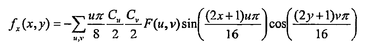
- A similar expression for spatial gradient fy (x, y) can also be obtained. An average gradient over the complete image block can then be calculated as a weighted sum:

where w(x, y) is some spatial weighting function. A popular weighting function to choose is a Gaussian. However, by choosing the weighting function:
for the x direction, the average gradient expression simplifies as follows:
where Cu and Cv being functions of u and v that equal
- Similar analysis can be performed for
fy . Thus with appropriate weighting the AC[1] (F(1,0)) and AC[8] (F(0,1)) coefficients can be interpreted as negative weighted average gradients over the DCT data block. - To summarise the above equations, the coefficients AC[1] and AC[8] approximate to the average spatial gradient within a block:


- Instead of constructing a matrix for the gradients at each pixel and then averaging, as in the Lucas Kanade method, the preferred embodiment of the present invention uses the steps of averaging the gradients (i.e. using the DCT coefficients) and then constructing a single matrix M':

- This matrix will, by definition, be singular with only one significant eigenvalue:

which gives a measure of the confidence of the motion vector in the direction of the eigenvector:
- A strong eigenvalue signals a large image gradient, e.g. an edge, in this block and the associated eigenvector will be normal to the edge's direction. Only the magnitude of λ1 has been used as a confidence measure, but the difference between the direction of the motion vector and e 1 could also be analyzed.
- M' can be related to the corresponding Lucas Kanade matrix
M to show that the resulting confidence estimates are inherently conservative. The details of this are given in Appendix A. - An MPEG-2 compressed video data stream has a variable number of DCT blocks for each macroblock that varies with the chroma quantization encoding parameter. Only the luminance DCT blocks are used in this embodiment, because there are always four per data macroblock (unlike the chrominance blocks that can have two, four or eight). Another reason is that the standard Lucas Kanade method only uses luminance values, so that, since the preferred embodiment attempts to approximate it, it should use only luminance as well.
Figure 4 shows an example of a confidence map, generated from the AC[1] and AC[8] coefficients, of the form AC[1]2 + AC[8]2, and its correlation with edge strength. - As previously noted, not every data macroblock has one associated motion vector. In order to obtain a smooth motion field, a number of rules are implemented as follows:
- 1) Macroblocks with no motion vector have the same movement as in the previous image.
- 2) When a macroblock has two motion vectors, the one pointing back is reversed and added to the one pointing forward.
- 3) Motion vector magnitude is normalized (motion vectors in P pictures span three images but this does not happen with motion vectors in B pictures, so that scaling is required).
- 4) Skipped macroblocks in 1-pictures have no movement while in P pictures they have movement similar to the previous block.
- Applying these rules removes the dependency on specific MPEG-2 characteristics, such as picture and macroblock type, and creates a motion field with one vector per macroblock with standardized magnitude. A spatial median filter is then applied to remove isolated vectors that have a low probability of reflecting real movement in the image.
Figures 5a and 5b illustrate some stages of this process,Figure 5a showing the original image, andFigure 5b showing the raw vectors extracted from the data macroblocks of the compressed video data stream.Figure 5c shows the motion field after application of the above rules, andFigure 5d shows the smoothed motion field. - Since P and B pictures transmit mostly inter-coded blocks, the confidence map is only fully-defined for I pictures that typically only occur every 12 pictures. The typical picture sequence of
Figure 1 illustrates this. A confidence map update step is required and the preferred embodiment exploits the fact that, even if the new exact confidence of a predicted data macroblock is unknown, the confidence of the original 16x16 area that the corresponding motion vector points at may be estimated.Figure 6 illustrates how an inter-coded macroblock (in this case from a P picture) relates to a corresponding I picture confidence map. Since motion vectors in MPEG-2 compressed video data have half-pixel accuracy, they rarely point to the top-left corner of a DCT data block, so that interpolation is required. The typical scenario will be that the new confidence is a weighted average of four DCT blocks.Figure 7 shows how DCT blocks may be used to estimate the confidence of an error block. - There are two obvious problems that can arise from such an approach, namely excessive averaging and error propagation. In fact, every confidence map update step involves interpolating new confidences and the confidence map is only reset on I pictures that occur every 12 pictures in a typical IBBPBBPBBPBB sequence. In practice, this problem is not that serious if adequate measures are taken. An obvious measure is that updates should be kept to a minimum in order to avoid excessive blurring of the confidence map. In fact, an update is only necessary when a vector is larger than half a DCT data block, if a vector is smaller than this there is a low probability that that edge has moved significantly. Also, since motion vectors of a P picture only refer to the previous I or P picture, there is a maximum of three update steps, making error propagation less serious. Confidence map updating in B pictures may depend on the magnitude of motion present in the compressed video data sequence.
- Areas of the image from which edges have moved are unreliable, so that either new edges move to these areas or they are marked with zero confidence. This happens when a moving object uncovers unknown background, possibly generating random motion that, since it has zero confidence, is ignored.
- The method of the preferred embodiment will now be described with reference to
Figure 16 as a sequence of steps that may be carried out within a digital processor under the control of a computer program. Encoded image data representative of an image of a changing object, preferably in an MPEG-2 encoded format, is supplied to the digital processor from a video camera, for example.Step 1 corresponds to obtaining a frame header from the encoded image data, which, for an MPEG-2 data stream, will comprise information describing whether the frame is an I, B or P picture. - At step 2 a decision is made as to whether or not the encoded video data frame incorporates motion vector encoding. Pictures used exclusively for reference purposes do not contain motion vector encoding, whereas predicted pictures contain motion vector information describing how to obtain the predicted picture from a reference picture. When the encoded video data is MPEG-2 encoded data, I pictures have no motion vector encoding, whereas both B and P pictures do incorporate motion vector encoding. The decision is therefore made on the basis of information extracted from the frame header.
- If the decision made at
step 2 is that the encoded image data does not incorporate motion vector encoding then, atstep 3, first frame data blocks not incorporating motion vector encoding are extracted. In the case of MPEG-2 encoded data, this step comprises extracting macroblocks of the I pictures yielding DCT coefficients. AC coefficients AC[1] and AC[8] are a subset of the DCT coefficients, and provide information on the strength and direction of edges in the real image. - At
step 4 the encoded image data not containing motion vector encoding is used to generate a confidence map indicative of the edge strength within the image data and hence the accuracy of the motion field. The AC[1] and AC[8] coefficients are used to create the confidence map for MPEG-2 encoded data. - If the decision made at
step 2 is that the encoded image data does incorporate motion vector encoding then, atstep 5, second frame data blocks incorporating motion vector encoding are extracted. In the case of MPEG-2 encoded data, this step comprises extracting macroblocks of the B and P pictures. - At
step 6, the second frame data blocks are used to derive smooth motion field data blocks in which each data block has a single motion vector and the magnitudes of the motion vectors are normalised. This is achieved by application of a set of rules which compensate for not every macroblock having one motion vector or motion vectors of a normalised magnitude. As noted above, such rules remove the dependency on the specific format in which the image data is encoded. - The confidence map data determined in
step 4 above is updated atstep 7 on the basis of the smooth motion field data blocks derived instep 6. The motion vectors relate regions of the first frame data blocks to regions of the second frame data blocks. This provides a function taking the confidence map from the first frame onto the second frame. Because the motion vectors typically do not exactly map a DCT block in an I image to a DCT block in a P or B image it is necessary to interpolate across the confidence map as depicted inFigure 6 . In one embodiment the new confidence map is a weighted average of the confidence values for the neighbouring 4 DCT blocks as shown inFigure 7 . -
Steps step 8. - To obtain a dense optical flow field the high confidence optical flow data can be spatially interpolated as performed in
step 9. - Both the motion vector field and the associated confidence map are accordingly estimated. Magnitude and confidence map thresholding can be applied to remove the majority of the noisy vectors, removing glow effects of lights on shiny surfaces and shadows.
- Such data is somewhat sensitive to a fixed threshold and accordingly a motion segmentation algorithm using the motion estimation of the preferred embodiment could use more flexible decision methods (adaptive thresholding, multi-step thresholding, probabilistic models, etc.). For the above-mentioned pedestrian detection scenario a fixed threshold is sufficient, and accordingly the examples referred to below use this for simplicity of visualization of the results.
- Using the scene of
Figures 8a and8b by way of a first example, the effect of using confidence thresholding to remove illumination noise and increase the accuracy of the motion estimation can be observed. In this specific scene, bright lights and a shiny pavement generate a lot of apparent motion that does not reflect real motion (Figure 9 ). The majority of the illumination noise is removed except for the noise on the handrails where there are strong edges and a lot of apparent motion.Figures 10a and 10b show the noise reduction effect of the confidence map before and after thresholding respectively. Such noise can be dealt with by a subsequent motion segmentation algorithm. A second example is shown inFigures 11a and 11b with the thresholded low-resolution motion field (16x16 blocks) in a scene with moving objects being shown before and after confidence thresholding inFigures 11a and 11b respectively. - Motion fields generated according to the Lucas Kanade method provide dense motion maps in that a motion vector is provided for every pixel. This can be seen in
Figure 12a where pixels with vectors pointing right are shown in white and vectors pointing left are show in grey for the sub-sampled Lucas Kanade motion field.Figure 12b shows the same scene, with the MPEG-2 smooth motion field. For ease of comparisonFigure 13a shows this Lucas Kanade motion field subsampled to the same resolution as the proposed scheme, andFigure 13b shows how successfully the smooth motion field of the present invention approximates it.Figures 14a and14b show both motion fields corresponding to another situation (that depicted inFigure 5a ), these figures showing the subsampled Lucas Kanade and MPEG-2 smooth motion fields respectively. A close match may be observed between the Lucas Kanade motion field and that of the preferred embodiment of the present invention. - An example of the blurring effect caused by the confidence map update step is shown in
Figures 15a and 15b . The most severe case is presented (after three update steps) to show that, even with some blurring, the approximation is still quite accurate. Some definition is lost in the shape of the object, but most of the motion is still correct.Figure 15a shows the MPEG-2 smooth motion field, andFigure 15b the Lucas Kanade motion field. - The approximation to the Lucas Kanade method of optical flow estimation provided by the preferred embodiment of the present invention is obtained at very low computational cost. All of the operations are simple and are applied to a small data set (44*30 macroblocks, 44*30*4 DCT blocks). This, allied with minimal MPEG-2 decoding, easily allows frame rates of over 25 images per second with unoptimised code. A rough comparison with Lucas Kanade method code shows that the algorithm of the preferred embodiment is approximately 50 times faster. With appropriate optimization, faster performance is possible. Given its low complexity, the method of the present invention may be implemented in a low cost real time optical flow estimator based around an inexpensive digital signal processing chipset.
- Although the smoothing effect of the weighted averaging is small, it is possible that it may be reduced even further. Object segmentation is likely to improve it, reducing blurring significantly and allowing more robust motion estimation. A more specific improvement would be to use low-resolution DC images for static camera applications where a background subtraction technique, allied with the motion estimation of the present invention, might be used for robust foreground object detection and tracking.
- The present invention provides a method for estimating optical flow, particularly optical flow as estimated by the well-known Lucas Kanade method, using only compressed video data. It will be appreciated by the person skilled in the art that various modifications may be made to the above described embodiments without departing from the scope of the present invention.
- The Lucas Kanade and present invention matrices can be approximately characterized as follows:


respectively, where E{o} represents expectation over the image pixels and the scale difference in M' has been ignored. It then follows from Jensen's inequality (see Cover and Thomas, "Elements of Information Theory" 1991, Wiley & Sons.) that for any direction w:
where (wTM w)-1 represents the variance of the optical flow estimate in the direction w for the Lucas Kanade method. Thus the singular matrix M' always gives larger variance estimates, so that it is an inherently conservative confidence measure.
Claims (10)
- An optical flow estimation method comprising the steps of:(a) obtaining encoded image data representative of an image sequence of a changing object having a motion field, wherein the encoded image data is MPEG-2 encoded video data;(b) extracting, from said encoded image data, first frame data blocks of intra-coded frame data, wherein the first frame data blocks extracted from said encoded image data are representative of a discrete cosine transform, DCT, of luminance data of said encoded image data;(c) extracting, from said encoded image data, second frame data blocks of predicted frame data and bi-directionally interpolated frame data;(d) determining, from said first frame data blocks, confidence map data indicative of the edge strength within said encoded image data and hence the accuracy of the motion field, wherein the confidence map data is determined from the weighted AC [1] and AC [8] coefficients of the discrete cosine transform, DCT, of said luminance data of said encoded video data representative of the intensity gradients in mutually transverse directions;(e) deriving, from said second frame data blocks, smooth motion field data blocks in which each data block is compensated to have a single motion vector and the magnitudes of the motion vectors are normalised; and(f) updating the confidence map data on the basis of the smooth motion field data blocks to provide output data indicative of the optical flow of the image, wherein the confidence map data is updated when the vector of a smooth motion field data block has a magnitude exceeding a certain threshold.
- A method according to Claim 1, wherein the confidence map data is determined from the sum of the squares of the weighted AC coefficients of the discrete cosine transform, DCT, representative of the intensity gradients in mutually transverse directions.
- A method according to Claim 1 or Claim 2, wherein the smooth motion field data blocks are derived from said second frame data blocks by a transformation in which, where a second frame data block has two motion vectors pointing in opposite directions, the corresponding field data block is ascribed a motion vector in one of the directions having a magnitude corresponding to the sum of the magnitudes of said two motion vectors pointing in opposite directions.
- A method according to any one of Claims 1 to 3, wherein the smooth motion field data blocks are derived from said second frame data blocks using spatial filtering to suppress isolated smooth motion field data blocks having a low probability of reflecting real movement.
- An optical flow estimation system utilising encoded image data representative of an image sequence of a changing object having a motion field which is adapted to receive MPEG-2 encoded video data, the system comprising:(a) first extraction means for extracting, from said encoded image data, first frame data blocks of intra-coded frame data, wherein the first frame data blocks extracted from said encoded image data are representative of a discrete cosine transform, DCT, of luminance data of said encoded image data;(b) second extraction means for extracting, from said encoded image data, second frame data blocks of predicted frame data and bi-directionally interpolated frame data;(c) determination means for determining, from said first frame data blocks, confidence map data indicative of the edge strength within said encoded image data and hence the accuracy of the motion field, wherein the determination means is arranged to determine the confidence map data from the weighted AC [1] and AC [8] coefficients of the discrete cosine transform, DCT, of said luminance data of said encoded video data representative of the intensity gradients in mutually transverse directions;(d) derivation means for deriving, from said second frame data blocks, smooth motion field data blocks in which each data block is compensated to have a single motion vector and the magnitudes of the motion vectors are normalised; and(e) updating means for updating said confidence map data on the basis of said smooth motion field data blocks to provide output data indicative of the optical flow of the image, wherein the confidence map data is updated when the vector of a smooth motion field data block has a magnitude exceeding a certain threshold.
- A system according to Claim 5, wherein the determination means is arranged to determine the confidence map data from the sum of the squares of the weighted AC coefficients of the discrete cosine transform, DCT, representative of the intensity gradients in mutually transverse directions.
- A system according to Claim 5 or Claim 6, wherein the derivation means is arranged to derive the smooth motion field data blocks from said second frame data blocks by a transformation in which, where a second frame data block has two motion vectors pointing in opposite directions, the corresponding field data block is ascribed a motion vector in one of the directions having a magnitude corresponding to the sum of the magnitudes of said two motion vectors pointing in opposite directions.
- A system according to any one of Claims 5 to 7 wherein the derivation means is arranged to derive the smooth motion field data blocks from said second frame data blocks using spatial filtering to suppress isolated smooth motion field data blocks having a low probability of reflecting real movement.
- A system according to any one of Claims 5 to 8 incorporating a digital processor.
- A computer readable recording medium on which is recorded an optical flow estimation program for causing a computer to execute the following steps:(a) extracting, from encoded image data representative of an image sequence of a changing object having a motion field, first frame data blocks of intra-coded frame data, wherein the encoded image data is MPEG-2 encoded video data and wherein the first frame data blocks extracted from said encoded image data are representative of a discrete cosine transform, DCT, of luminance data of said encoded image data;(b) extracting, from said encoded image data, second frame data blocks of predicted frame data and bi-directionally interpolated frame data;(c) determining, from said first frame data blocks, confidence map data indicative of the edge strength within said encoded image data and hence the accuracy of the motion field, wherein the confidence map data is determined from the weighted AC [1] and AC [8] coefficients of the discrete cosine transform, DCT, of said luminance data of said encoded video data representative of the intensity gradients in mutually transverse directions;(d) deriving, from said second frame data blocks, smooth motion field data blocks in which each data block is compensated to have a single motion vector and the magnitudes of the motion vectors are normalised; and(e) updating the confidence map data on the basis of the smooth motion field data blocks to provide output data indicative of the optical flow of the image, wherein the confidence map data is updated when the vector of a smooth motion field data block has a magnitude exceeding a certain threshold.
Applications Claiming Priority (2)
| Application Number | Priority Date | Filing Date | Title |
|---|---|---|---|
| GBGB0315412.7A GB0315412D0 (en) | 2003-07-02 | 2003-07-02 | Optical flow estimation method |
| PCT/EP2004/051325 WO2005006762A2 (en) | 2003-07-02 | 2004-07-01 | Optical flow estimation method |
Publications (2)
| Publication Number | Publication Date |
|---|---|
| EP1639829A2 EP1639829A2 (en) | 2006-03-29 |
| EP1639829B1 true EP1639829B1 (en) | 2014-09-17 |
Family
ID=27676466
Family Applications (1)
| Application Number | Title | Priority Date | Filing Date |
|---|---|---|---|
| EP04766110.3A Expired - Lifetime EP1639829B1 (en) | 2003-07-02 | 2004-07-01 | Optical flow estimation method |
Country Status (4)
| Country | Link |
|---|---|
| US (1) | US7822231B2 (en) |
| EP (1) | EP1639829B1 (en) |
| GB (1) | GB0315412D0 (en) |
| WO (1) | WO2005006762A2 (en) |
Families Citing this family (33)
| Publication number | Priority date | Publication date | Assignee | Title |
|---|---|---|---|---|
| US8036494B2 (en) * | 2004-04-15 | 2011-10-11 | Hewlett-Packard Development Company, L.P. | Enhancing image resolution |
| KR101044940B1 (en) * | 2004-06-23 | 2011-06-28 | 삼성전자주식회사 | Method and apparatus for deblocking using edge flow-directed filter and curvelet transform |
| US20060020562A1 (en) * | 2004-07-21 | 2006-01-26 | University Of Southern Mississippi | Apparatus and method for estimating optical flow |
| US7730406B2 (en) * | 2004-10-20 | 2010-06-01 | Hewlett-Packard Development Company, L.P. | Image processing system and method |
| US7760956B2 (en) | 2005-05-12 | 2010-07-20 | Hewlett-Packard Development Company, L.P. | System and method for producing a page using frames of a video stream |
| WO2006123309A2 (en) * | 2005-05-20 | 2006-11-23 | Koninklijke Philips Electronics N.V. | Video decoder using a reliability map |
| US8588513B2 (en) * | 2005-07-18 | 2013-11-19 | Broadcom Corporation | Method and system for motion compensation |
| US20070098274A1 (en) * | 2005-10-28 | 2007-05-03 | Honeywell International Inc. | System and method for processing compressed video data |
| KR100728031B1 (en) * | 2006-01-23 | 2007-06-14 | 삼성전자주식회사 | Method and apparatus for deciding encoding mode for variable block size motion estimation |
| KR101104144B1 (en) | 2006-03-23 | 2012-01-13 | 엔디에스 리미티드 | System for analysis of motion |
| US8542726B2 (en) * | 2006-10-17 | 2013-09-24 | Microsoft Corporation | Directional and motion-compensated discrete cosine transformation |
| DE102006053286A1 (en) | 2006-11-13 | 2008-05-15 | Robert Bosch Gmbh | Method for detecting movement-sensitive image areas, apparatus and computer program for carrying out the method |
| US8457410B2 (en) * | 2007-02-14 | 2013-06-04 | Technion Research And Development Foundation Ltd. | Over-parameterized variational optical flow method |
| FR2932036B1 (en) * | 2008-06-03 | 2011-01-07 | Thales Sa | METHOD AND SYSTEM FOR PROTECTING A COMPRESSED VIDEO STREAM AGAINST ERRORS ARISING DURING TRANSMISSION |
| US8922659B2 (en) | 2008-06-03 | 2014-12-30 | Thales | Dynamically reconfigurable intelligent video surveillance system |
| FR2932045B1 (en) | 2008-06-03 | 2010-08-20 | Thales Sa | METHOD AND SYSTEM FOR PROTECTING THE DATA CONFIDENTIALITY OF A VIDEO STREAM DURING ITS TRANSMISSION |
| FR2932046B1 (en) * | 2008-06-03 | 2010-08-20 | Thales Sa | METHOD AND SYSTEM FOR VISUALLY CRYPTING MOBILE OBJECTS WITHIN A COMPRESSED VIDEO STREAM |
| US8050459B2 (en) * | 2008-07-25 | 2011-11-01 | GM Global Technology Operations LLC | System and method for detecting pedestrians |
| FR2939546B1 (en) | 2008-12-05 | 2011-02-11 | Thales Sa | METHOD AND DEVICE FOR BURITING A BINARY SEQUENCE IN A COMPRESSED VIDEO STREAM |
| JP5115497B2 (en) * | 2009-02-27 | 2013-01-09 | 富士通セミコンダクター株式会社 | Image processing program, image processing apparatus, and image processing method |
| TWI419075B (en) * | 2010-05-14 | 2013-12-11 | Univ Nat Cheng Kung | Video warping graphic processor |
| JP5863273B2 (en) * | 2011-05-02 | 2016-02-16 | キヤノン株式会社 | Image processing apparatus, control method, and program |
| US8203605B1 (en) * | 2011-05-11 | 2012-06-19 | Google Inc. | Point-of-view object selection |
| JP2016521411A (en) * | 2013-04-10 | 2016-07-21 | オークランド ユニサービシズ リミテッド | Head and eye tracking |
| US9996935B2 (en) | 2014-10-10 | 2018-06-12 | Edan Instruments, Inc. | Systems and methods of dynamic image segmentation |
| US9819841B1 (en) | 2015-04-17 | 2017-11-14 | Altera Corporation | Integrated circuits with optical flow computation circuitry |
| AU2015202937A1 (en) * | 2015-05-29 | 2016-12-15 | Canon Kabushiki Kaisha | Systems and methods for registration of images |
| US20160377717A1 (en) * | 2015-06-29 | 2016-12-29 | Edan Instruments, Inc. | Systems and methods for adaptive sampling of doppler spectrum |
| CN106251304B (en) * | 2015-09-11 | 2019-09-17 | 深圳市理邦精密仪器股份有限公司 | Dynamic image segmented system and method |
| US11508061B2 (en) * | 2020-02-20 | 2022-11-22 | Siemens Healthcare Gmbh | Medical image segmentation with uncertainty estimation |
| CN112377332B (en) * | 2020-10-19 | 2022-01-04 | 北京宇航系统工程研究所 | Rocket engine polarity testing method and system based on computer vision |
| CN112700393A (en) * | 2020-12-29 | 2021-04-23 | 维沃移动通信(杭州)有限公司 | Image fusion method and device and electronic equipment |
| CN114581493A (en) * | 2022-03-04 | 2022-06-03 | 三星电子(中国)研发中心 | Bidirectional optical flow estimation method and device |
Family Cites Families (9)
| Publication number | Priority date | Publication date | Assignee | Title |
|---|---|---|---|---|
| JPH1091795A (en) * | 1996-09-12 | 1998-04-10 | Toshiba Corp | Device for detecting mobile object and method therefor |
| US6788802B2 (en) * | 1998-05-21 | 2004-09-07 | Sanyo Electric Co., Ltd. | Optical flow estimation method and image synthesis method |
| US6643387B1 (en) * | 1999-01-28 | 2003-11-04 | Sarnoff Corporation | Apparatus and method for context-based indexing and retrieval of image sequences |
| WO2000045339A1 (en) | 1999-01-28 | 2000-08-03 | Sarnoff Corporation | Apparatus and method for describing the motion parameters of an object in an image sequence |
| US6366701B1 (en) * | 1999-01-28 | 2002-04-02 | Sarnoff Corporation | Apparatus and method for describing the motion parameters of an object in an image sequence |
| WO2001096982A2 (en) | 2000-06-14 | 2001-12-20 | Dynapel Systems, Inc. | System for the estimation of optical flow |
| US7545957B2 (en) * | 2001-04-20 | 2009-06-09 | Avid Technology, Inc. | Analyzing motion of characteristics in images |
| US8218638B2 (en) * | 2007-10-31 | 2012-07-10 | Broadcom Corporation | Method and system for optical flow based motion vector estimation for picture rate up-conversion |
| US8259809B2 (en) * | 2009-01-12 | 2012-09-04 | Mediatek Singapore Pte Ltd. | One step sub-pixel motion estimation |
-
2003
- 2003-07-02 GB GBGB0315412.7A patent/GB0315412D0/en not_active Ceased
-
2004
- 2004-07-01 US US10/562,604 patent/US7822231B2/en not_active Expired - Fee Related
- 2004-07-01 EP EP04766110.3A patent/EP1639829B1/en not_active Expired - Lifetime
- 2004-07-01 WO PCT/EP2004/051325 patent/WO2005006762A2/en active Application Filing
Also Published As
| Publication number | Publication date |
|---|---|
| GB0315412D0 (en) | 2003-08-06 |
| WO2005006762A2 (en) | 2005-01-20 |
| US7822231B2 (en) | 2010-10-26 |
| EP1639829A2 (en) | 2006-03-29 |
| WO2005006762A3 (en) | 2005-02-10 |
| US20060188013A1 (en) | 2006-08-24 |
Similar Documents
| Publication | Publication Date | Title |
|---|---|---|
| EP1639829B1 (en) | Optical flow estimation method | |
| US5760846A (en) | Apparatus for estimating motion vectors for feature points of a video signal | |
| US5689306A (en) | Method and apparatus for encoding a video signal using pixel-by-pixel motion prediction | |
| EP1138152B1 (en) | Method and apparatus for performing hierarchical motion estimation using nonlinear pyramid | |
| JP4180666B2 (en) | Video signal encoding method | |
| KR0171118B1 (en) | Apparatus for encoding video signal | |
| US6249613B1 (en) | Mosaic generation and sprite-based coding with automatic foreground and background separation | |
| EP0849950A2 (en) | Dynamic sprites for encoding video data | |
| US8625678B2 (en) | Method for scalable video coding on a plurality of space resolution levels | |
| JPH03253190A (en) | Method and apparatus for hybrid coding for moving picture | |
| WO2009033152A2 (en) | Real-time video coding/decoding | |
| KR0174454B1 (en) | Method and apparatus for thinning edge line in feature point based motion compensation | |
| JPH08265781A (en) | Method and apparatus for determining movement vector | |
| Makar et al. | Interframe coding of canonical patches for low bit-rate mobile augmented reality | |
| JP3823767B2 (en) | Moving image foreground / background region separation method, and moving image encoding method using conditional pixel interpolation using the method | |
| US20110129012A1 (en) | Video Data Compression | |
| KR20060111528A (en) | Detection of local visual space-time details in a video signal | |
| Naman et al. | Inter-frame prediction using motion hints | |
| US5731851A (en) | Method for determining feature points based on hierarchical block searching technique | |
| US6020925A (en) | Method and apparatus for encoding a video signal using pixel-by-pixel motion prediction | |
| Kameda et al. | Multi-frame motion compensation using extrapolated frame by optical flow for lossless video coding | |
| JP2001346208A (en) | Image signal decoder and method | |
| Kim et al. | Stochastic approach for motion vector estimation in video coding | |
| Chan et al. | A novel predictive global motion estimation for video coding | |
| Fu et al. | Fast global motion estimation based on local motion segmentation |
Legal Events
| Date | Code | Title | Description |
|---|---|---|---|
| PUAI | Public reference made under article 153(3) epc to a published international application that has entered the european phase |
Free format text: ORIGINAL CODE: 0009012 |
|
| 17P | Request for examination filed |
Effective date: 20060113 |
|
| AK | Designated contracting states |
Kind code of ref document: A2 Designated state(s): DE FR GB |
|
| DAX | Request for extension of the european patent (deleted) | ||
| RBV | Designated contracting states (corrected) |
Designated state(s): DE FR GB |
|
| REG | Reference to a national code |
Ref country code: DE Ref legal event code: R079 Ref document number: 602004045855 Country of ref document: DE Free format text: PREVIOUS MAIN CLASS: H04N0007360000 Ipc: H04N0019513000 |
|
| GRAP | Despatch of communication of intention to grant a patent |
Free format text: ORIGINAL CODE: EPIDOSNIGR1 |
|
| RIC1 | Information provided on ipc code assigned before grant |
Ipc: G06T 7/20 20060101ALI20140325BHEP Ipc: H04N 19/513 20140101AFI20140325BHEP Ipc: H04N 19/51 20140101ALI20140325BHEP Ipc: H04N 19/48 20140101ALI20140325BHEP |
|
| INTG | Intention to grant announced |
Effective date: 20140409 |
|
| GRAS | Grant fee paid |
Free format text: ORIGINAL CODE: EPIDOSNIGR3 |
|
| GRAA | (expected) grant |
Free format text: ORIGINAL CODE: 0009210 |
|
| AK | Designated contracting states |
Kind code of ref document: B1 Designated state(s): DE FR GB |
|
| REG | Reference to a national code |
Ref country code: GB Ref legal event code: FG4D |
|
| REG | Reference to a national code |
Ref country code: DE Ref legal event code: R096 Ref document number: 602004045855 Country of ref document: DE Effective date: 20141023 |
|
| REG | Reference to a national code |
Ref country code: DE Ref legal event code: R097 Ref document number: 602004045855 Country of ref document: DE |
|
| PLBE | No opposition filed within time limit |
Free format text: ORIGINAL CODE: 0009261 |
|
| STAA | Information on the status of an ep patent application or granted ep patent |
Free format text: STATUS: NO OPPOSITION FILED WITHIN TIME LIMIT |
|
| 26N | No opposition filed |
Effective date: 20150618 |
|
| REG | Reference to a national code |
Ref country code: FR Ref legal event code: PLFP Year of fee payment: 13 |
|
| REG | Reference to a national code |
Ref country code: FR Ref legal event code: PLFP Year of fee payment: 14 |
|
| REG | Reference to a national code |
Ref country code: FR Ref legal event code: PLFP Year of fee payment: 15 |
|
| PGFP | Annual fee paid to national office [announced via postgrant information from national office to epo] |
Ref country code: GB Payment date: 20220627 Year of fee payment: 19 |
|
| PGFP | Annual fee paid to national office [announced via postgrant information from national office to epo] |
Ref country code: FR Payment date: 20220616 Year of fee payment: 19 |
|
| PGFP | Annual fee paid to national office [announced via postgrant information from national office to epo] |
Ref country code: DE Payment date: 20220615 Year of fee payment: 19 |
|
| P01 | Opt-out of the competence of the unified patent court (upc) registered |
Effective date: 20230527 |
|
| REG | Reference to a national code |
Ref country code: DE Ref legal event code: R119 Ref document number: 602004045855 Country of ref document: DE |
|
| GBPC | Gb: european patent ceased through non-payment of renewal fee |
Effective date: 20230701 |
|
| PG25 | Lapsed in a contracting state [announced via postgrant information from national office to epo] |
Ref country code: DE Free format text: LAPSE BECAUSE OF NON-PAYMENT OF DUE FEES Effective date: 20240201 Ref country code: GB Free format text: LAPSE BECAUSE OF NON-PAYMENT OF DUE FEES Effective date: 20230701 |
|
| PG25 | Lapsed in a contracting state [announced via postgrant information from national office to epo] |
Ref country code: FR Free format text: LAPSE BECAUSE OF NON-PAYMENT OF DUE FEES Effective date: 20230731 |