JP2004096557A - Image processor and image processing method - Google Patents
Image processor and image processing method Download PDFInfo
- Publication number
- JP2004096557A JP2004096557A JP2002256841A JP2002256841A JP2004096557A JP 2004096557 A JP2004096557 A JP 2004096557A JP 2002256841 A JP2002256841 A JP 2002256841A JP 2002256841 A JP2002256841 A JP 2002256841A JP 2004096557 A JP2004096557 A JP 2004096557A
- Authority
- JP
- Japan
- Prior art keywords
- frame
- shape data
- image
- data
- comparing
- Prior art date
- Legal status (The legal status is an assumption and is not a legal conclusion. Google has not performed a legal analysis and makes no representation as to the accuracy of the status listed.)
- Withdrawn
Links
- 238000003672 processing method Methods 0.000 title claims abstract description 19
- 238000012545 processing Methods 0.000 claims abstract description 87
- 238000012937 correction Methods 0.000 claims abstract description 69
- 230000002159 abnormal effect Effects 0.000 claims abstract description 62
- 230000005856 abnormality Effects 0.000 claims abstract description 7
- 230000000007 visual effect Effects 0.000 claims abstract description 6
- 238000000034 method Methods 0.000 claims description 73
- 230000033001 locomotion Effects 0.000 claims description 57
- 230000008569 process Effects 0.000 claims description 22
- 238000000605 extraction Methods 0.000 claims description 17
- 238000001514 detection method Methods 0.000 claims description 13
- PXFBZOLANLWPMH-UHFFFAOYSA-N 16-Epiaffinine Natural products C1C(C2=CC=CC=C2N2)=C2C(=O)CC2C(=CC)CN(C)C1C2CO PXFBZOLANLWPMH-UHFFFAOYSA-N 0.000 claims description 10
- 230000009466 transformation Effects 0.000 claims description 10
- 230000005484 gravity Effects 0.000 claims description 4
- 230000008859 change Effects 0.000 abstract description 14
- 239000000284 extract Substances 0.000 abstract 1
- 238000010586 diagram Methods 0.000 description 18
- 230000006870 function Effects 0.000 description 10
- 238000011410 subtraction method Methods 0.000 description 4
- 238000005286 illumination Methods 0.000 description 3
- 238000013139 quantization Methods 0.000 description 3
- 238000004364 calculation method Methods 0.000 description 2
- 230000008929 regeneration Effects 0.000 description 2
- 238000011069 regeneration method Methods 0.000 description 2
- 230000002194 synthesizing effect Effects 0.000 description 2
- 238000012795 verification Methods 0.000 description 2
- 230000005540 biological transmission Effects 0.000 description 1
- 230000000052 comparative effect Effects 0.000 description 1
- 239000000470 constituent Substances 0.000 description 1
- 230000006866 deterioration Effects 0.000 description 1
- 230000000694 effects Effects 0.000 description 1
- 238000005516 engineering process Methods 0.000 description 1
- 238000011156 evaluation Methods 0.000 description 1
- 238000003384 imaging method Methods 0.000 description 1
- 230000006872 improvement Effects 0.000 description 1
- 238000012958 reprocessing Methods 0.000 description 1
- 238000007619 statistical method Methods 0.000 description 1
- 238000013519 translation Methods 0.000 description 1
Images


Classifications
-
- G—PHYSICS
- G06—COMPUTING; CALCULATING OR COUNTING
- G06T—IMAGE DATA PROCESSING OR GENERATION, IN GENERAL
- G06T9/00—Image coding
- G06T9/001—Model-based coding, e.g. wire frame
-
- G—PHYSICS
- G06—COMPUTING; CALCULATING OR COUNTING
- G06T—IMAGE DATA PROCESSING OR GENERATION, IN GENERAL
- G06T7/00—Image analysis
- G06T7/20—Analysis of motion
- G06T7/254—Analysis of motion involving subtraction of images
-
- G—PHYSICS
- G06—COMPUTING; CALCULATING OR COUNTING
- G06T—IMAGE DATA PROCESSING OR GENERATION, IN GENERAL
- G06T9/00—Image coding
- G06T9/20—Contour coding, e.g. using detection of edges
-
- H—ELECTRICITY
- H04—ELECTRIC COMMUNICATION TECHNIQUE
- H04N—PICTORIAL COMMUNICATION, e.g. TELEVISION
- H04N19/00—Methods or arrangements for coding, decoding, compressing or decompressing digital video signals
- H04N19/20—Methods or arrangements for coding, decoding, compressing or decompressing digital video signals using video object coding
-
- H—ELECTRICITY
- H04—ELECTRIC COMMUNICATION TECHNIQUE
- H04N—PICTORIAL COMMUNICATION, e.g. TELEVISION
- H04N19/00—Methods or arrangements for coding, decoding, compressing or decompressing digital video signals
- H04N19/50—Methods or arrangements for coding, decoding, compressing or decompressing digital video signals using predictive coding
- H04N19/503—Methods or arrangements for coding, decoding, compressing or decompressing digital video signals using predictive coding involving temporal prediction
- H04N19/51—Motion estimation or motion compensation
- H04N19/537—Motion estimation other than block-based
- H04N19/543—Motion estimation other than block-based using regions
-
- H—ELECTRICITY
- H04—ELECTRIC COMMUNICATION TECHNIQUE
- H04N—PICTORIAL COMMUNICATION, e.g. TELEVISION
- H04N19/00—Methods or arrangements for coding, decoding, compressing or decompressing digital video signals
- H04N19/60—Methods or arrangements for coding, decoding, compressing or decompressing digital video signals using transform coding
- H04N19/61—Methods or arrangements for coding, decoding, compressing or decompressing digital video signals using transform coding in combination with predictive coding
-
- G—PHYSICS
- G06—COMPUTING; CALCULATING OR COUNTING
- G06T—IMAGE DATA PROCESSING OR GENERATION, IN GENERAL
- G06T2207/00—Indexing scheme for image analysis or image enhancement
- G06T2207/10—Image acquisition modality
- G06T2207/10016—Video; Image sequence
Landscapes
- Engineering & Computer Science (AREA)
- Multimedia (AREA)
- Physics & Mathematics (AREA)
- General Physics & Mathematics (AREA)
- Theoretical Computer Science (AREA)
- Signal Processing (AREA)
- Computer Vision & Pattern Recognition (AREA)
- Compression Or Coding Systems Of Tv Signals (AREA)
- Image Analysis (AREA)
Abstract
Description
【0001】
【発明の属する技術分野】
本発明は、動画像中に含まれる対象物を抽出して異常フレームを検出する画像処理装置及び画像処理方法に関する。
【0002】
【従来の技術】
近年、デジタル技術を利用して画像を対象物(オブジェクト)毎に分離、合成する処理が注目されている。特に、動画像の符号化においては、国際標準としてMPEG−4符号化方式が規格化されている。MPEG−4符号化方式では、オブジェクト毎の符号化/復号化が可能となり、符号化効率の向上、伝送路に応じたデータ配分、画像の再加工等の従来は困難であったさまざまな応用が期待されている。
【0003】
また、動画像処理における対象物の抽出方法としては、一般に背景差分方式という手法が知られている。これは、予め撮影した背景画像と実際の入力画像とを比較することにより、変化点を検出する方法である。以下、簡単にその原理について説明する。
【0004】
まず、画像平面上の座標(x,y)における点の入力画像の画素値をPc(x,y)、背景画像の画素値をPb(x,y)とする。このとき、Pc(x,y)とPb(x,y)との差分をとり、その絶対値をあるしきい値Thと比較する。
【0005】
判定式の例を示すと次の通りである。
|Pc(x,y)−Pb(x,y)| ≦ Th … (1)
そして、式(1)において差分絶対値がしきい値Th以下の場合、この点(x,y)は変化なしということで、Pcは背景と判定される。一方、差分絶対値がしきい値Thを超えている場合は、値が変化したということで抽出対象とみなされる。画面上のすべての点において上記の判定を行うことで、1フレーム分の抽出が完了する。
【0006】
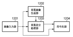
図13は、背景差分方式とMPEG−4符号化方式を組み合わせた従来のシステムの構成を示すブロック図である。図13において、画像入力部1201は、例えばカメラの撮像部であり、動画像を入力する部分である。また、背景差分法では参照する背景画像が必要となるため、背景画像生成部1202において背景画像を生成する。これは、予め対象物が映っていない状態で1フレーム分の画像を取り込むことによって生成することが最も簡単な方法である。
【0007】
また、背景差分処理部1203では、画像入力部1201からの入力画像と背景生成部1202からの参照画像とから、対象物の形状データを生成する。さらに、符号化部1204では、画像入力部1201からの入力画像と背景差分処理部からの形状データとがフレーム単位で入力され、符号化処理が行われる。以下、符号化部1204を、MPEG−4符号化方式として説明する。
【0008】
オブジェクト(対象物)を符号化する場合には、オブジェクトの形と位置の情報を符号化する必要がある。そのために、まず、オブジェクトを内包する矩形領域を設定し、この矩形の左上位置の座標と矩形領域の大きさを符号化する。この矩形領域はバウンディングボックスと呼ばれる。また、画像信号、形状信号により表現されるオブジェクト内部の領域をVOP(Video Object Plane)と呼ぶ。
【0009】
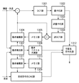
図14は、従来のVOP符号化を行う符号化部1204の細部構成を示すブロック図である。尚、入力される信号は画像の輝度・色差信号と形状信号であり、それらはマクロブロック単位で処理される。
【0010】
まず、イントラモードでは、各ブロックをDCT部1301において離散コサイン変換(DCT)し、量子化部1302で量子化する。量子化されたDCT係数と量子化幅は、可変長符号化部1312で可変長符号化される。
【0011】
一方、インターモードでは、動き検出部1307において時間的に隣接する別のVOPの中からブロックマッチングをはじめとする動き検出方法により動きを検出し、動きベクトル予測部1308で対象マクロブロックに対して誤差のもっとも小さい予測マクロブロックを検出する。誤差の最も小さい予測マクロブロックへの動きを示す信号が動きベクトルである。尚、予測マクロブロックを生成するために参照する画像を参照VOPと呼ぶ。
【0012】
検出された動きベクトルに基づいて、参照VOPを動き補償部1306において動き補償し、最適な予測マクロブロックを取得する。次に対象となるマクロブロックと対応する予測マクロブロックとの差分を求め、この差分信号に対してDCT部1301でDCTを施し、DCT変換係数を量子化部1302で量子化する。
【0013】
一方、形状データは、形状符号化CAE部1309で符号化される。但し、ここで実際にCAE符号化が行われるのは境界ブロックのみであり、VOP内のブロック(ブロック内全てのデータがオブジェクト内)やVOP外のブロック(ブロック内全てのデータがオブジェクト外)はヘッダ情報のみが可変長符号化部1312に送られる。また、CAE符号化が施される境界ブロックは、画像データと同様に、インターモードにおいては、動き検出部1307による動き検出を行い、動きベクトル予測部1308動きベクトルの予測を行う。そして、動き補償した形状データと前フレームの形状データとの差分値に対しCAE符号化を行う。
【0014】
【発明が解決しようとする課題】
しかしながら、上述した背景差分法には、以下に説明する2つの問題がある。一つ目の問題として、この方式は背景画像が変化しないことを前提としており、照明変化等により背景の値が変化した場合は、安定した抽出結果が得られないという問題がある。この問題の対応策としては、背景画像の変化を統計的な手法により検出し、適宜背景画像を更新するという方法が、特開平7―302328号等に開示されている。
【0015】
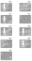
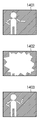
2つ目の問題は、シーン中にフラッシュが当たったり、対象物の前を別の物体が横切ったときなどの対応である。これらの場合を図を用いて説明する。図15は、従来例におけるシーン中にフラッシュが当たった場合の対象物の形状データについて説明するための図である。1401がある時間のフレームデータ、1402が次の時間のフレームデータで、このときフラッシュが当たっている。そして、1403はその次の時間のフレームデータである。このように、フラッシュが当たったフレーム(1402)は他の抽出結果(1401、1403)と大きく異なるものになってしまう。
【0016】
一つ目の問題である背景の照明変化の場合は、主に輝度値の変化のみであるが、二つ目の問題であるフラッシュの場合には、色相も変化してしまうので、背景の正確な補正は困難である。また、仮に、対象物の正確な形状データが得られたとしても、対象物そのものの画像データも大きく変化してしまっているため、フレーム間差分を用いるMPEG−4のような方式では、符号化効率を上げることができず、視覚的にも不自然なものとなってしまう。
【0017】
図16は、従来例における対象物の前を別の物体が横切った場合の対象物の形状データについて説明するための図である。図16において、1501は別の物体(例えば、車両)が横切る直前のフレームデータ、1502と1503は車両が対象物(人)の前を横切っているときのフレームデータ、1504は車両が横切った直後のフレームデータである。このように、別の物体も併せて抽出してしまうと、形状データと画像データが大きく変化することによる情報量の増大のため、大きな画質劣化を招いてしまう。この場合、背景の照明変化とは全く別の現象のため、背景画像を更新方法で対応することは困難である。
【0018】
本発明は、このような事情を考慮してなされたものであり、動画像中の対象物の形状データが一時的に大きく変化した場合であっても、修正対象となるフレームを好適に検出して修正し、視覚的にも符号化効率的にも優れた動画像符号化をすることができる画像処理装置及び画像処理方法を提供することを目的とする。
【0019】
【課題を解決するための手段】
上記課題を解決するため、本発明に係る画像処理装置は、複数のフレームから構成される動画像を入力する動画像入力手段と、入力された前記動画像に関する背景画像を取得する背景画像取得手段と、前記動画像を構成するそれぞれのフレームと前記背景画像とを比較して対象物を抽出する対象物抽出手段と、抽出された前記対象物の形状データの異常の有無を判定する異常データ判定手段と、前記形状データの判定結果に基づいて該形状データを修正する形状データ修正手段と、前記形状データ修正手段で修正された前記形状データに応じた前記対象物の画像データを生成する画像データ修正手段と、前記形状データと前記画像データとを符号化する符号化手段とを備えることを特徴とする。
【0020】
また、本発明に係る画像処理装置は、前記異常データ判定手段が、時間的に異なる複数のフレーム間で前記対象物の前記形状データを比較して、該形状データの修正の必要性を判定することを特徴とする。
【0021】
さらに、本発明に係る画像処理装置は、前記異常データ判定手段が、現フレームと前フレームとを用いて前記対象物の形状データを比較する第1の比較手段と、前フレームと後フレームとを用いて前記対象物の形状データを比較する第2の比較手段と、現フレームと前フレームとの間で前記対象物の形状データの差分が大きい場合であって、前フレームと後フレームとの間で前記対象物の形状データの差分が小さい場合、現フレームの修正が必要であると判定する判定手段とを備えることを特徴とする。
【0022】
さらにまた、本発明に係る画像処理装置は、前記異常データ判定手段が、現フレームと前フレームとを用いて前記対象物の形状データを比較する第1の比較手段と、現フレームと後フレームとを用いて前記対象物の形状データを比較する第2の比較手段と、現フレームと前フレームとの間で前記対象物の形状データの差分が大きい場合であって、現フレームと後フレームとの間で前記対象物の形状データの差分が大きい場合、現フレームの修正が必要であると判定する判定手段とを備えることを特徴とする。
【0023】
さらにまた、本発明に係る画像処理装置は、前記異常データ判定手段が、現フレームと前フレームとを用いて前記対象物の形状データを比較する第1の比較手段と、現フレーム以降のフレームと前フレームとを用いて前記対象物の前記形状データを比較する第2の比較手段と、現フレームと前フレームとの間の差分が大きい場合、前フレームと現フレーム以降のフレームとの間で前記対象物の形状データの差分が小さい場合、現フレーム以降の所定のフレームの修正が必要であると判定する判定手段とを備えることを特徴とする。
【0024】
さらにまた、本発明に係る画像処理装置は、前記第1又は第2の比較手段が、前記形状データの面積、周囲長、ウェーブレット識別子、円形度、重心又はモーメントのいずれかによる比較若しくはそれらの組み合わせを用いて比較することを特徴とする。
【0025】
さらにまた、本発明に係る画像処理装置は、前記形状データ修正手段が、異常と判定されたN番目のフレームにおける前記対象物の形状データを、正常と判定されたN−1番目以前のフレームと正常と判定されたN+1番目以降のフレームとを用いて修正することを特徴とする。
【0026】
さらにまた、本発明に係る画像処理装置は、前記形状データ修正手段が、さらに、N−1番目以前のフレームとN+1番目以降のフレーム間の前記形状データ上の対応点を検出する検出手段をさらに備えることを特徴とする。
【0027】
さらにまた、本発明に係る画像処理装置は、前記検出手段が、一つ又は複数の所定領域毎のパターンマッチングにより、前記対応点の動き量を求めることを特徴とする。
【0028】
さらにまた、本発明に係る画像処理装置は、前記対応点の動き量が、アフィン変換による該対応点の位置の移動量と回転量とであることを特徴とする。
【0029】
さらにまた、本発明に係る画像処理装置は、前記形状データ修正手段が、異常と判定されたN番目のフレームにおける形状データを正常と判定されたN−1番目以前のフレームの形状データに置き換えることを特徴とする。
【0030】
さらにまた、本発明に係る画像処理装置は、前記画像データ修正手段が、現フレームとは時間的に異なるフレームから前記対象物の画像データを生成することを特徴とする。
【0031】
さらにまた、本発明に係る画像処理装置は、前記画像データ修正手段が、異常と判定されたN番目のフレームを、正常と判定されたN−1番目のフレームと正常と判定されたN+1番目のフレームとから生成することを特徴とする。
【0032】
さらにまた、本発明に係る画像処理装置は、前記画像データ修正手段が、異常と判定されたN番目のフレームを正常と判定されたN−1番目のフレームに置き換えることを特徴とする。
【0033】
さらにまた、本発明に係る画像処理装置は、前記符号化手段が、MPEG−4ビジュアル符号化方式に準じた符号化手段であることを特徴とする。
【0034】
【発明の実施の形態】
以下、図面を参照して、本発明の好適な実施形態について詳細に説明する。
【0035】
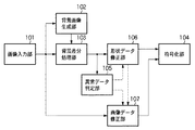
図1は、本発明の一実施形態に係る画像処理装置の構成を示すブロック図である。図1において、画像入力部101、背景画像生成部102、背景差分処理部103、符号化部104は、図14を用いて説明した画像入力部1201、背景画像生成部1202、背景差分処理部1203、符号化部1204と同一の機能を有する。すなわち、本実施形態では、符号化部104が、MPEG−4ビジュアル符号化方式に準じた符号化処理をすることを特徴とする。
【0036】
本実施形態に係る画像処理装置はそれに加えて、さらに次に示す構成要素を備える。
【0037】
すなわち、異常データ判定部105は、背景差分処理部103からの形状データを検証して異常を検出する。形状データ修正部106は、異常データ判定部105で異常が検出された場合に形状データの修正を行う。そして、画像データ修正部107は、形状データ修正部106で修正した形状データに合わせて画像データの修正を行う。尚、変更された画像データと形状データは、符号化部104に入力され、符号化が行われる。
【0038】
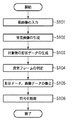
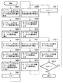
図2は、本発明の一実施形態に係る画像処理装置の動作手順を説明するためのフローチャートである。図2に示すように、画像入力部101から動画像が入力され(ステップS101)、背景画像生成部102で背景画像(参照画像)が生成される(ステップS102)。そして、背景差分処理部103で、画像入力部101からの入力画像と背景生成部102からの参照画像とから、対象物の形状データを生成する(ステップS103)。そして、異常データ判定部105で異常フレームの判定がされ(ステップS104)、前記対象物の形状データの修正及び画像データの修正がそれぞれ形状データ修正部106、画像データ修正部107で行われる(ステップS105)。そして、符号化部104で、修正後の画像データと形状データとが符号化される(ステップS106)。
【0039】
すなわち、本実施形態に係る画像処理装置は、画像入力部101から複数のフレームから構成される動画像を取得し、背景画像生成部102で動画像に関する背景画像を取得し、背景差分処理部103で動画像を構成するそれぞれのフレームと背景画像とを比較して対象物を抽出し、異常データ判定部105で抽出された対象物の形状データの異常の有無を判定し、異常と判定された場合、形状データ修正部106で形状データを修正し、形状データ修正部106で修正された形状データを用いて画像データ修正部107でフレームを修正し、修正された形状データと画像データとを符号化部104で符号化することを特徴とする。
【0040】
以下、ステップS104の異常フレームの判定と、ステップS105の形状データ及び画像データの修正処理とについて以下の2つの実施形態に適用して詳細に説明する。尚、それ以外の処理手順については上述のとおりである。
【0041】
<第1の実施形態>
本発明の第1の実施形態に係る画像処理装置について、図3から図8を用いて説明する。これは、図15を用いて説明した問題(シーン中にフラッシュが当たった場合)に対応する処理である。
【0042】
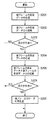
図3は、第1の実施形態における異常データ判定部105におけるフラッシュの当たった異常フレームの検出手順を説明するためのフローチャートである。まず、異常データ判定部105においては、現フレームの形状データが生成される(ステップS201)。これは、従来技術と同様の背景差分法を用いて抽出した結果のデータである。次に、前フレームの形状データと現フレームの形状データの比較が行われる(ステップS202)。
【0043】
ここで、形状データの比較の方法として、いくつかの方法が考えられる。面積の比較は、最も簡単な比較例の一つである。例えば、オブジェクトとみなされた形状データの画素数がオブジェクトの面積となる。また、周囲長をパラメータとすることも可能であり、さらにはフーリエ記述子を用いた曲線表現も可能である。これらの詳細な説明については、「画像処理工学 基礎編」谷口慶治・編に詳しく記載されている。尚、本実施形態においては、形状データの比較にどのパラメータを選んでもよく、方式に何ら制限を加えるものではない。すなわち、本実施形態では、形状データの比較方法として、形状データの面積、周囲長、ウェーブレット識別子、円形度、重心又はモーメントのいずれかによる比較若しくはそれらの組み合わせを用いて比較することを特徴とする。
【0044】
そして、比較結果に応じた処理の分岐が行われる(ステップS203)。その結果、差分が小さい場合(No)は異常なしと判定され、差分が大きい場合(Yes)は形状データの検証が行われる。例えば、図15における1401を前フレームの形状データ、1402を現フレームの形状データとすると、フレーム間の差分が大きいため1402が異常フレームかどうかの検証が行われる。
【0045】
検証の手順としては、まず、後フレームの形状データが生成される(ステップS204)。次に、前フレームの形状データと後フレームの形状データとの比較を行う(ステップS205)。この場合の比較の方法は、ステップS202における比較方法と同じものでよい。そして、比較結果に応じた処理の分岐を行う(ステップS206)。
【0046】
ステップS206における判定で、差分が小さい場合(Yes)、現フレームの形状データが異常であると判断する。一方、差分が大きい場合(No)、瞬間的な変化ではないため、フラッシュではないと判断する。例えば、図13においては、1401が前フレーム、1403が後フレームの形状データである。そして、前フレームのデータ1401と後フレームのデータ1403との差分が小さいので、1402はフラッシュの当たったフレーム(異常のフレーム)と判定される。そして、異常と判定された場合は、現フレームのデータ(形状データ及び画像データ)の修正(再生成)を行う(ステップS207)。
【0047】
すなわち、本実施形態に係る画像処理装置では、異常データ判定部105が、時間的に異なる複数のフレーム間で対象物の形状データを比較して、当該形状データの修正の必要性を判定することを特徴とする。
【0048】
また、本実施形態に係る画像処理装置では、異常データ判定部105が、現フレームと前フレームとを用いて対象物の形状データを比較し(ステップS202)、前フレームと後フレームとを用いて対象物の形状データを比較し(ステップS205)、現フレームと前フレームとの間で対象物の形状データの差分が大きい場合であって、前フレームと後フレームとの間で対象物の形状データの差分が小さい場合、現フレームの修正が必要であると判定することを特徴とする。
【0049】
尚、ステップS207における修正処理については、後に詳しく説明する。
【0050】
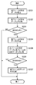
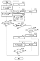
次に、図4は、第1の実施形態における異常データ判定部105におけるフラッシュの当たったフレームを検出する他の判定手順を説明するためのフローチャートである。図4のフローチャートにおいては、ステップS208、S209以外の処理ステップは全て図3のフローチャートと同じ処理ステップである。
【0051】
ステップS208では、現フレームの形状データと後フレームの形状データの比較が行われる。また、ステップS209における判定では、差分が大きい場合はフラッシュであり、差分が小さい場合はフラッシュではないと判定する。ここで、差分が小さい場合とは、オブジェクトの状態が遷移して、新たな状態になったと考えることができる。例えば、図15では、現フレームの形状データ1402と後フレームの形状データ1403の差分が大きいため、1402はフラッシュの当たったフレームと判定される。
【0052】
また、特殊な例として、形状データの急激な変化がフラッシュ以外に考えられないような場合には、後フレームのデータを使用することなく、ステップS203の判定結果のみでステップS207の処理に移ることも可能である。
【0053】
すなわち、本実施形態に係る画像処理装置では、異常データ判定部105が、現フレームと前フレームとを用いて対象物の形状データを比較し(ステップS202)、現フレームと後フレームとを用いて対象物の形状データを比較し(ステップS208)、現フレームと前フレームとの間で対象物の形状データの差分が大きい場合であって、現フレームと後フレームとの間で対象物の形状データの差分が大きい場合、現フレームの修正が必要であると判定することを特徴とする。
【0054】
次に、修正が必要と判定されたフレームの処理(ステップS207)について説明する。
【0055】
図5は、本発明の第1の実施形態における形状データと画像データの修正手順を説明するためのフローチャートである。ここで、抽出対象が剛体の場合は全体が1つの動きであるが、そうでない場合は局所的に別の動きをする部分が現れる。そこで、以下では、全体の動きが一致する対応領域を「共通領域」、それ以外の局所的な動きをする領域を「動領域」と称す。
【0056】
まず、形状データ修正部106では、前後のフレームの形状データから共通領域が検出される(ステップS301)。これは、前フレームの形状データと後フレームの形状データのAND処理をすることで簡単に求めることができる。図7は、本発明の第1の実施形態における形状データについて説明するための図である。図7において、501は前フレームの形状データ、502は後フレームの形状データ、503はこの2フレームから検出した共通領域を示す。
【0057】
また、画像データ修正部107では、現フレームの画像データの共通領域が生成される(ステップS302)。これは、前フレームの画像データと後フレームの画像データの平均値を求めることによって生成する。すなわち、ある点(x,y)の前フレームにおける画素値をPp(x,y)、後フレームにおける画素値をPb(x,y)とすると、平均値は、(Pp(x,y)+Pb(x,y))/2で求めることができる。
【0058】
一方、形状データ修正部106では、前フレームの形状データの動領域が検出される(ステップS303)。これは、前フレームの形状データ501と前後フレームの共通領域503のXOR処理で求めることができる。図7において、504は検出された前フレームの動領域である。
【0059】
また、画像データ修正部107では、前フレームの画像データの動領域が検出される(ステップS304)。これは、検出した動領域の形状データの位置に画像データをそのまま対応付ければよい。同様に、形状データ修正部106では、後フレームの形状データの動領域が求められる(ステップS305)。この場合も、後フレームの形状データ502と前後フレームの共通領域503のXOR処理で求めることができ、図7における505が検出結果である。そして、画像データ修正部107では、後フレームの画像データの動領域が検出される(ステップS306)。これも、検出した動領域の形状データの位置に画像データをそのまま対応付ければよい。
【0060】
次に、形状データ修正部106では、前後フレーム間の形状データの動領域の動きが検出される(ステップS307)。対応点の検出には、アフィン変換などを使ったパターンマッチングを用いる。アフィン変換の一例を以下に示す。
X=(x−x0)cosθ−(y−y0)sinθ+x0
Y=(x−x0)sinθ+(y−y0)cosθ+y0 … (2)
ここで、(x0,y0)が回転の中心、θが回転角となる。パターンマッチングは、この計算で求めた値と実際の値との差分の総和若しくは差分の二乗和を評価値とし、この値が最小となるような回転の中心位置および回転角を求める。
【0061】
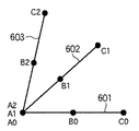
図8は、第1の実施形態における形状データの対応点検出結果を模式的に説明するための図である。ここでは簡単のため形状を線分として説明する。図8において、線分601が前フレーム、603が後フレームのデータを表しているものとする。この場合、線分601と線分603とのなす角がこのアフィン変換における回転角であり、A0とA2の重なっている点の位置が回転の中心である。尚、B0、C0に対応する点がそれぞれB2、C2である。
【0062】
次に、形状データ修正部106では、現フレームの形状データの動きが算出される(ステップS308)。動きが、図8に示すように回転角と回転の中心位置で求まる場合には、回転角をθ/2、回転の中心位置をA0にすることで、動き量を求めることができる。
【0063】
さらに、形状データ修正部106では、現フレームの形状データの動領域が生成される(ステップS309)。すなわち、ステップS308で算出したパラメータを代入して対応点が求められる。これによって、A0とA2に対応する点がA1、B0とB2に対応する点がB1、C0とC2に対応する点がC1となる。そして、対応する点をすべて結んだ線分602が現フレームの形状データとなる。図7の506はこのようにして求めた現フレームの動領域の形状データを示している。
【0064】
すなわち、本実施形態では、形状データ修正部106が、異常と判定されたN番目のフレームにおける対象物の形状データを、正常と判定されたN−1番目以前のフレームと正常と判定されたN+1番目以降のフレームとを用いて修正することを特徴とする。
【0065】
また、本実施形態では、形状データ修正部106が、N−1番目以前のフレームとN+1番目以降のフレーム間の形状データ上の対応点を検出することを特徴とする。さらに、本実施形態では、形状データ修正部106が、一つ又は複数の所定領域毎のパターンマッチングにより、対応点の動き量を求めることを特徴とする。さらにまた、本実施形態では、対応点の動き量が、アフィン変換による該対応点の位置の移動量と回転量とであることを特徴とする。
【0066】
次に、画像データ修正部107では、ステップS309で生成した形状データに対応した画像データを生成する(ステップS310)。すなわち、ステップS308で求めたパラメータを利用して、A1の画素値はA0とA2の平均値、B1の画素値はB0とB2の平均値、といったように対応点間の平均値から求める。尚、平均値の求め方はステップS302で説明した手順と同様である。
【0067】
そして、形状データ修正部106では、ステップS301で求めた共通領域の形状データと、ステップS309で求めた動領域の形状データを合成し、現フレームの形状データが再生成される(ステップS311)。図7の507はこのようにして求めた現フレームの形状データを示している。さらに、画像データ修正部107では、ステップS302で求めた共通領域の画像データと、ステップS310で求めた動領域の画像データを合成し、現フレームの画像データが再生成される(ステップS312)。
【0068】
上述した手順によって、現フレームの形状データと画像データが再生成できた時点で、この処理は完了となる。これらのデータは上述したように図1の符号化部104に入力され、MPEG−4符号化が行われる。
【0069】
上述したように、第1の実施形態に係る画像形成装置によれば、フラッシュの当たった画像のような、形状データが不連続となるフレームを検出し、当該フレームを前後フレームから修正することにより、形状データと画像データ共に、余計な符号量発生を抑え、視覚的にも良好な符号化システムを実現することができる。
【0070】
<第2の実施形態>
本発明の第2の実施形態について、図9から図12を用いて説明する。これは、図16を用いて説明した問題(対象物の前を抽出対象でない他の物体が横切った場合)に対応する処理である。
【0071】
図9は、第2の実施形態における異常データ判定部105の動作手順を説明するためのフローチャートである。ステップS701からS703の処理は、第1の実施形態で説明した図3のステップS201からS203と同じ処理である。但し、ここでは現フレームをN番目のフレームとして説明する。また、図16において、1501から1504を順にN−1、N、N+1、N+2フレーム目の形状データであるとする。この例では、ステップS703において、現フレームの形状データ1502と前フレームの形状データ1501とを比較し、差分が大きい(Yes)ので、形状データの検証が行われる。
【0072】
ここで、抽出対象でない他の物体が前を横切る場合は、複数フレームにわたって大きな形状変化が検出されると考えられる。1フレームだけに出現するものではないからである。そこで、このフレーム数をカウントするための初期化処理として、カウンタmを1にセットする(ステップS704)。
【0073】
次に、N+1フレーム(現フレームの次のフレーム)の形状データを生成する(ステップS705)。図16の1503がこのフレームの形状データである。そして、生成したN+1フレームの形状データと、N−1フレームの形状データとの比較を行う(ステップS706)。比較の方法は、ステップS703における方法と同じ方法でよい。そして、両者の差分が小さいか否かを判定する(ステップS707)。その結果、差分が小さい場合(Yes)、現フレームの形状データのみが異常であると判断する。一方、差分が大きい場合(No)、次のフレームも検証の対象と判断する。図16に示す例では、1501と1503の比較となり、差分は大きいと判断される。
【0074】
そこで、カウンタmが最大値maxに達したかどうかの判定をする(ステップS708)。この最大値maxは、抽出対象でない他の物体が前を横切ると考えられる最大時間を予め設定しておく。例えば、フレームレートが15fpsで、最大2秒程度と考えられる場合には、maxを30と設定する。そして、カウンタmが最大値maxに達していない場合(No)、カウンタmの値を1つ増やす(ステップS709)。
【0075】
一方、ステップS708においてカウンタmが最大値maxに達してしまった場合(Yes)、エラー処理を行う(ステップS710)。この場合、何かが抽出対象を横切ったというわけでなく、抽出対象そのものの形状が大きく変化したと考える。また、修正しない形状データをそのまま使っての問題ない場合は、特にエラー処理は行わず、このフレームの処理を終了するようにしてもよい。
【0076】
上述したステップS705からS709の処理を繰り返し、ステップS707で、差分が小さいと判定した場合(Yes)、このループを抜ける。このときのカウンタ値mが抽出結果が異常と判定されたフレームの数であり、再生成の必要なフレーム数である。図16の例では、mが2となった時点で、1501の形状データと1504の形状データとが比較され、このループを抜ける。
【0077】
また、ステップS711からS714では、検出したmフレーム分のデータ修正(再生成)処理が行われる。まず、フレーム数のカウンタkを0にセットする初期化処理が行われる(ステップS711)。また、ステップS712は、修正処理のメインの部分であり、詳細は後に説明する。さらに、終了判定がされ(ステップS713)、kがm−1になるまでステップS714においてkの値を1つずつ増やし、この処理を繰り返す。そして、NフレームからN+m−1フレームまでのデータ再生成が終了すると、一連の処理が終了する。図16の例では、mが2であり、1502と1503のフレームのデータを再生成することになる。
【0078】
尚、図9のフローチャートでは、N番目のフレームの処理例を説明したが、データ修正が行われた場合は、次に処理するフレームは、N+1番目ではなく、N+m+1番目からであっても構わない。
【0079】
すなわち、本実施形態に係る画像処理装置では、異常データ判定部105が、現フレームと前フレームとを用いて対象物の形状データを比較し(ステップS702)、現フレーム以降のフレームと前フレームとを用いて対象物の形状データを比較し(ステップS706)、現フレームと前フレームとの間の差分が大きい場合、前フレームと現フレーム以降のフレームとの間で対象物の形状データの差分が小さい場合、現フレーム以降の所定のフレームの修正が必要であると判定することを特徴とする。
【0080】
次に、修正が必要と判定されたフレームの修正処理について説明する。図10は、第2の実施形態に係る形状データと画像データの修正手順を説明するためのフローチャートである。まず、N−1フレームとN+mフレームの形状データから、共通の領域を検出する(ステップS801)。これは、図5で説明したときと同様に、N−1フレームの形状データとN+mフレームの形状データのAND処理をすることで簡単に求めることができる。但し、図5の場合と違い、フレーム間の時間間隔が長い場合は、共通領域も動いてしまっていることが考えられる。この場合には、抽出対象全体の動きを、パターンマッチングにより求めるようにする。図5で説明したようなアフィン変換を用いると、フレーム間の抽出対象の平行移動量と回転量を求めることができる。
【0081】
すなわち、N−1フレームからN+mフレームまでの回転角がθであるとし、その移動量が、(x0,y0)であったとすると、N+kフレームにおける回転角は、θ×(k+1)/(m+1)となり、移動量は、(x0×(k+1)/(m+1),y0×(k+1)/(m+1))となる。これらのパラメータにより位置を合わせた後、AND処理をすることで、共通領域を検出することができる。
【0082】
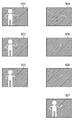
図11は、第2の実施形態に係る形状データを説明するための図である。図11の例では、1001がN−1フレームの形状データ、1002がN+2フレームの形状データを示している。尚、共通領域の動きはないので、回転角は0、移動量は(0,0)である。また、1003は、1001と1002から求めた共通領域を示している。
【0083】
次に、共通領域以外に局所的な動きがある場合は、動領域の検出を行う。まず、N−1フレームの形状データの動領域を検出する(ステップS802)。これは、N−1フレームの形状データ1001と共通領域1003の位置を合わせた後、XOR処理で求めることができる。1004は検出されたN−1フレームの動領域である。次に、N−1フレームの画像データの動領域を検出する(ステップS803)。これは、ステップS802で求めた領域に対応する画像データである。
【0084】
同様に、N+mフレームの形状データの動領域を検出する(ステップS804)。これは、N+mフレームの形状データ1002と共通領域1003の位置を合わせた後、XOR処理で求めることができる。1005は検出されたN−1フレームの動領域である。次に、N+mフレームの画像データの動領域を検出する(ステップS805)。これも、ステップS804で求めた領域に対応する画像データである。
【0085】
次に、N−1フレームとN+mフレーム間の形状データの動領域の動きを検出する(ステップS806)。これは、N−1フレームの形状データ1004とN+mフレームの形状データ1005の対応点を検出ということである。対応点の検出には、アフィン変換などを使ったパターンマッチングを用いる。
【0086】
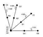
図12は、第2の実施形態における形状データの対応点検出の処理を模式的に説明するための図である。ここでも簡単のため形状を線分として説明する。線分1101がN−1フレーム、線分1104がN+mフレームのデータを表している。線分1101と線分1104のなす角がこのアフィン変換における回転角θ’であり、A0、A3の重なっている点の位置が回転の中心(x’0,y’0)である。B0、C0に対応する点がそれぞれB3、C3である。
【0087】
以下のステップで、修正する各フレームの処理を行う。まず、初期化処理を行う(ステップS807)。ここでは、修正するフレーム数をカウントするカウンタkを0にセットする。次に、N+kフレームにおける共通領域の動きを算出する(ステップS808)。これは、ステップS801で求めた動き量から算出する。図11の例では、回転角0、移動量(0,0)である。そして、ステップS808で求めた値から共通領域の形状データを生成する(ステップS809)。図11の例では、共通領域の移動量は0なので、Nフレームにおける形状データの共通領域は1003と一致する。
【0088】
次に、ステップS809で求めた形状データに対応した画像データを生成する(ステップS810)。このとき、ある点(x,y)のN−1フレームにおける画素値をP0(x,y)、N+mフレームにおける画素値をPm(x,y)とすると、N+kフレームにおける画素値は、(P0(x,y)×(m−k)+Pm(x,y)×(k+1))/(m+1)となる。また、共通領域にほとんど変化がないと考えられる場合は、簡易的な方法として、平均値(P0(x,y)+Pm(x,y))/2を用いてもよい。さらに簡単には、P0(x,y)をそのまま利用することも考えられる。これは、N−1フレームの画像データをそのままコピーするということである。
【0089】
次に、N+kフレームにおける動領域の動きを算出する(ステップS811)。これは、先に求めたN−1フレームにおける動領域とN+mフレームにおける動領域との間の動き検出から求める。N−1フレームからN+mフレームまでの回転角がθ’で、その移動量が、(x’0,y’0)であるので、N+kフレームにおける回転角は、θ’×(k+1)/(m+1)となり、移動量は、(x’0×(k+1)/(m+1),y’0×(k+1)/(m+1))となる。m=2のとき、Nフレームにおける回転角は、θ’/3、移動量は(x’0/3,y’0/3)となる。
【0090】
そして、ステップS811で求めた値から、動領域の形状データを生成する(ステップS812)。図12において、線分1101に対し、回転角θ’/3、移動量は(x’0/3,y’0/3)に対応する点を求めると、線分1102が得られる。次に、動領域の形状データに対応する画像データを生成する(ステップS813)。方法は共通領域における画素値の算出と同じである。このとき、ある点(x’,y’)のN−1フレームにおける画素値をP’0(x’,y’)、N+mフレームにおける画素値をP’m(x’,y’)とすると、N+kフレームにおける画素値は、(P’0(x’,y’)×(m−k)+P’m(x’,y’)×(k+1))/(m+1)となる。
【0091】
さらに、N+kフレームの形状データを再生成する(ステップS814)。これは、ステップS809で求めた共通領域の形状データとステップS812で求めた動領域の形状データを合成したものとなる。図11の1008は、Nフレームにおける再生成した形状データである。次に、N+kフレームの画像データを再生成する(ステップS815)。これは、ステップS810で求めた共通領域の画像データとステップS813で求めた動領域の画像データを合成したものとなる。
【0092】
そして、フレーム数の判定を行い(ステップS816)、m−1に満たない場合(No)、ステップS817においてkの値を1つ増し、ステップS808からの処理を繰り返す。一方、mが2の場合は、NフレームとN+1フレームのデータを再生成して一連の処理を終える。N+1フレームにおいては、回転角がθ’×2/3、移動量が(x’0×2/3,y’0×2/3)であり、対応点を求めると図12の線分1103が得られる。また、図11の1007は、N+1フレームにおける形状データの動領域、1009は、N+1フレームにおける再生成した形状データである。
【0093】
ここでは、共通領域以外の局所的な動きは1種類として説明したが、複数の動きが存在する場合は、動きの数だけ動領域検出の処理を繰り返せばよい。
【0094】
上述したように第2の実施形態によれば、抽出対象の前を他の物体が横切った時の画像のような、形状データが不連続となる複数のフレームを検出し、当該フレームを前後フレームから修正することにより、形状データと画像データ共に、余計な符号量発生を抑え、視覚的にも良好な符号化システムを実現することができる。
【0095】
<第3の実施形態>
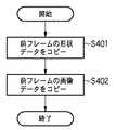
また、図6は、第3の実施形態における形状データと画像データの修正に関する他のフローチャートである。すなわち、本実施形態では、上述した第1及び第2の実施形態における形状データ修正部106及び画像データ修正部107での形状データ及び画像データの修正処理を、正常と判定されたフレームの形状データ及び画像データに置き換える(コピー)処理をするものである。
【0096】
すなわち、本実施形態では、形状データ修正部106が、異常と判定されたN番目のフレームにおける形状データを正常と判定されたN−1番目以前のフレームの形状データに置き換える(ステップS401)ことを特徴とする。また、画像データ修正部107が、異常と判定されたN番目のフレームを、正常と判定されたN−1番目のフレームと正常と判定されたN+1番目のフレームとから生成することを特徴とする。さらに、画像データ修正部107が、異常と判定されたN番目のフレームを正常と判定されたN−1番目のフレームに置き換える(ステップS402)ことを特徴とする。
【0097】
<他の実施形態>
尚、本発明は、複数の機器(例えば、ホストコンピュータ、インタフェース機器、リーダ、プリンタ等)から構成されるシステムに適用しても、一つの機器からなる装置(例えば、複写機、ファクシミリ装置等)に適用してもよい。
【0098】
また、本発明の目的は、前述した実施形態の機能を実現するソフトウェアのプログラムコードを記録した記録媒体(または記憶媒体)を、システムあるいは装置に供給し、そのシステムあるいは装置のコンピュータ(またはCPUやMPU)が記録媒体に格納されたプログラムコードを読み出し実行することによっても、達成されることは言うまでもない。この場合、記録媒体から読み出されたプログラムコード自体が前述した実施形態の機能を実現することになり、そのプログラムコードを記録した記録媒体は本発明を構成することになる。また、コンピュータが読み出したプログラムコードを実行することにより、前述した実施形態の機能が実現されるだけでなく、そのプログラムコードの指示に基づき、コンピュータ上で稼働しているオペレーティングシステム(OS)などが実際の処理の一部または全部を行い、その処理によって前述した実施形態の機能が実現される場合も含まれることは言うまでもない。
【0099】
さらに、記録媒体から読み出されたプログラムコードが、コンピュータに挿入された機能拡張カードやコンピュータに接続された機能拡張ユニットに備わるメモリに書き込まれた後、そのプログラムコードの指示に基づき、その機能拡張カードや機能拡張ユニットに備わるCPUなどが実際の処理の一部または全部を行い、その処理によって前述した実施形態の機能が実現される場合も含まれることは言うまでもない。
【0100】
本発明を上記記録媒体に適用する場合、その記録媒体には、先に説明したフローチャートに対応するプログラムコードが格納されることになる。
【0101】
【発明の効果】
以上説明したように、本発明によれば、動画像中の対象物の形状データが一時的に大きく変化した場合であっても、修正対象となるフレームを好適に検出して修正し、視覚的にも符号化効率的にも優れた動画像符号化をすることができる。
【図面の簡単な説明】
【図1】本発明の一実施形態に係る画像処理装置の構成を示すブロック図である。
【図2】本発明の一実施形態に係る画像処理装置の動作手順を説明するためのフローチャートである。
【図3】第1の実施形態における異常データ判定部105におけるフラッシュの当たった異常フレームの検出手順を説明するためのフローチャートである。
【図4】第1の実施形態における異常データ判定部105におけるフラッシュの当たったフレームを検出する他の判定手順を説明するためのフローチャートである。
【図5】本発明の第1の実施形態における形状データと画像データの修正手順を説明するためのフローチャートである。
【図6】第3の実施形態における形状データと画像データの修正に関する他のフローチャートである。
【図7】本発明の第1の実施形態における形状データについて説明するための図である。
【図8】第1の実施形態における形状データの対応点検出結果を模式的に説明するための図である。
【図9】第2の実施形態における異常データ判定部105の動作手順を説明するためのフローチャートである。
【図10】第2の実施形態に係る形状データと画像データの修正手順を説明するためのフローチャートである。
【図11】第2の実施形態に係る形状データを説明するための図である。
【図12】第2の実施形態における形状データの対応点検出の処理を模式的に説明するための図である。
【図13】背景差分方式とMPEG−4符号化方式を組み合わせた従来のシステムの構成を示すブロック図である。
【図14】従来のVOP符号化を行う符号化部1204の細部構成を示すブロック図である。
【図15】従来例におけるシーン中にフラッシュが当たった場合の対象物の形状データについて説明するための図である。
【図16】従来例における対象物の前を別の物体が横切った場合の対象物の形状データについて説明するための図である。
【符号の説明】
101 画像入力部
102 背景画像生成部
103 背景差分処理部
104 符号化部
105 異常データ判定部
106 形状データ修正部
107 画像データ修正部[0001]
TECHNICAL FIELD OF THE INVENTION
The present invention relates to an image processing apparatus and an image processing method for extracting an object included in a moving image and detecting an abnormal frame.
[0002]
[Prior art]
2. Description of the Related Art In recent years, attention has been paid to a process of separating and synthesizing an image for each object using digital technology. In particular, in encoding moving images, the MPEG-4 encoding method has been standardized as an international standard. The MPEG-4 encoding system enables encoding / decoding for each object, and enables various applications, such as improvement of encoding efficiency, data distribution according to a transmission path, and image reprocessing, which were conventionally difficult. Expected.
[0003]
As a method of extracting an object in moving image processing, a technique called a background subtraction method is generally known. This is a method of detecting a change point by comparing a previously captured background image with an actual input image. Hereinafter, the principle will be briefly described.
[0004]
First, let Pc (x, y) be the pixel value of the input image at a coordinate (x, y) on the image plane, and Pb (x, y) be the pixel value of the background image. At this time, the difference between Pc (x, y) and Pb (x, y) is obtained, and the absolute value is compared with a certain threshold Th.
[0005]
An example of the determination formula is as follows.
| Pc (x, y) -Pb (x, y) | ≦ Th (1)
If the absolute value of the difference is equal to or smaller than the threshold value Th in Equation (1), this point (x, y) does not change, and Pc is determined to be the background. On the other hand, if the absolute difference value exceeds the threshold value Th, the value has changed, and it is regarded as an extraction target. By performing the above determination at all points on the screen, extraction for one frame is completed.
[0006]
FIG. 13 is a block diagram showing the configuration of a conventional system combining the background difference method and the MPEG-4 encoding method. In FIG. 13, an
[0007]
The background
[0008]
When encoding an object (object), it is necessary to encode information on the shape and position of the object. For that purpose, first, a rectangular area including the object is set, and the coordinates of the upper left position of the rectangle and the size of the rectangular area are encoded. This rectangular area is called a bounding box. A region inside the object represented by the image signal and the shape signal is called a VOP (Video Object Plane).
[0009]
FIG. 14 is a block diagram showing a detailed configuration of an
[0010]
First, in the intra mode, each block is subjected to discrete cosine transform (DCT) in the
[0011]
On the other hand, in the inter mode, a
[0012]
Based on the detected motion vector, the
[0013]
On the other hand, shape data is encoded by a shape encoding
[0014]
[Problems to be solved by the invention]
However, the above-described background subtraction method has two problems described below. The first problem is that this method is based on the assumption that the background image does not change. If the value of the background changes due to a change in illumination or the like, there is a problem that a stable extraction result cannot be obtained. As a countermeasure against this problem, a method of detecting a change in the background image by a statistical method and appropriately updating the background image is disclosed in JP-A-7-302328 and the like.
[0015]
The second problem is a countermeasure when a flash hits the scene or another object crosses the object. These cases will be described with reference to the drawings. FIG. 15 is a diagram for explaining shape data of an object when a flash hits a scene in a conventional example. 1401 is frame data of a certain time, and 1402 is frame data of the next time. At this time, a flash is applied.
[0016]
In the case of the background illumination change, which is the first problem, only a change in the luminance value is mainly involved, but in the case of the flash, which is the second problem, the hue also changes. Correction is difficult. Even if accurate shape data of the object is obtained, the image data of the object itself has changed greatly. Therefore, in a method such as MPEG-4 using the difference between frames, encoding is not performed. Efficiency cannot be improved, and it becomes visually unnatural.
[0017]
FIG. 16 is a diagram for explaining shape data of an object when another object crosses in front of the object in the conventional example. In FIG. 16, 1501 is frame data immediately before another object (for example, a vehicle) crosses, 1502 and 1503 are frame data when a vehicle crosses in front of an object (person), and 1504 is immediately after a vehicle crosses. Is the frame data. As described above, if another object is also extracted, a large change in shape data and image data causes an increase in the amount of information, thereby causing a large deterioration in image quality. In this case, it is difficult to update the background image by the update method because the phenomenon is completely different from the change in the illumination of the background.
[0018]
The present invention has been made in view of such circumstances, and even when the shape data of an object in a moving image temporarily changes significantly, it is possible to appropriately detect a frame to be corrected. It is an object of the present invention to provide an image processing apparatus and an image processing method that can perform moving image coding that is excellent both visually and coding efficiency.
[0019]
[Means for Solving the Problems]
In order to solve the above problems, an image processing apparatus according to the present invention includes a moving image input unit that inputs a moving image composed of a plurality of frames, and a background image obtaining unit that obtains a background image related to the input moving image. Object extraction means for extracting an object by comparing each frame constituting the moving image with the background image; and abnormal data determination for judging whether or not the extracted shape data of the object is abnormal. Means, shape data correcting means for correcting the shape data based on the determination result of the shape data, and image data for generating image data of the object corresponding to the shape data corrected by the shape data correcting means It is characterized by comprising correction means and coding means for coding the shape data and the image data.
[0020]
In the image processing apparatus according to the present invention, the abnormal data determination unit determines the necessity of correcting the shape data by comparing the shape data of the object between a plurality of temporally different frames. It is characterized by the following.
[0021]
Further, in the image processing apparatus according to the present invention, the abnormal data determination unit may include a first comparison unit that compares the shape data of the object using a current frame and a previous frame, and a front frame and a rear frame. A second comparing means for comparing the shape data of the object using the first frame and a case where a difference between the shape data of the object between the current frame and the previous frame is large, and And determining means for determining that the current frame needs to be corrected when the difference between the shape data of the object is small.
[0022]
Still further, in the image processing apparatus according to the present invention, the abnormal data determination unit may include a first comparison unit that compares the shape data of the object using a current frame and a previous frame; And a second comparing means for comparing the shape data of the object using the method described above, wherein the difference between the shape data of the object is large between the current frame and the previous frame, and A determination unit that determines that the current frame needs to be corrected when the difference between the shape data of the target object is large.
[0023]
Still further, in the image processing apparatus according to the present invention, the abnormal data determination unit may include a first comparison unit that compares the shape data of the object using a current frame and a previous frame, and a frame after the current frame. Second comparing means for comparing the shape data of the object using a previous frame, and when a difference between the current frame and the previous frame is large, the second comparing means compares the previous frame with the frames after the current frame. When the difference between the shape data of the object is small, a determination unit that determines that correction of a predetermined frame after the current frame is necessary is provided.
[0024]
Still further, in the image processing apparatus according to the present invention, the first or second comparing unit may perform comparison based on any of the area, perimeter, wavelet identifier, circularity, center of gravity, or moment of the shape data, or a combination thereof. The comparison is made using
[0025]
Still further, in the image processing apparatus according to the present invention, the shape data correction unit may convert the shape data of the target object in the N-th frame determined to be abnormal with the (N-1) -th and previous frames determined to be normal. The correction is performed by using the (N + 1) th and subsequent frames determined to be normal.
[0026]
Still further, in the image processing apparatus according to the present invention, the shape data correction unit may further include a detection unit configured to detect a corresponding point on the shape data between the (N−1) th frame and the (N + 1) th and subsequent frames. It is characterized by having.
[0027]
Still further, the image processing apparatus according to the present invention is characterized in that the detecting means obtains a motion amount of the corresponding point by performing pattern matching for one or a plurality of predetermined regions.
[0028]
Still further, the image processing apparatus according to the present invention is characterized in that the movement amount of the corresponding point is a movement amount and a rotation amount of the position of the corresponding point by affine transformation.
[0029]
Still further, in the image processing apparatus according to the present invention, the shape data correction unit may replace the shape data in the N-th frame determined to be abnormal with the shape data of the (N−1) -th frame determined to be normal. It is characterized by.
[0030]
Furthermore, the image processing apparatus according to the present invention is characterized in that the image data correcting means generates image data of the object from a frame temporally different from a current frame.
[0031]
Still further, in the image processing apparatus according to the present invention, the image data correction unit may convert the N-th frame determined to be abnormal to the (N-1) -th frame determined to be normal and the (N + 1) -th frame determined to be normal. And a frame.
[0032]
Still further, the image processing apparatus according to the present invention is characterized in that the image data correcting means replaces the N-th frame determined to be abnormal with the (N-1) -th frame determined to be normal.
[0033]
Still further, the image processing apparatus according to the present invention is characterized in that the encoding means is an encoding means conforming to the MPEG-4 visual encoding method.
[0034]
BEST MODE FOR CARRYING OUT THE INVENTION
Hereinafter, preferred embodiments of the present invention will be described in detail with reference to the drawings.
[0035]
FIG. 1 is a block diagram illustrating a configuration of an image processing apparatus according to an embodiment of the present invention. 1, an
[0036]
The image processing apparatus according to the present embodiment further includes the following constituent elements.
[0037]
That is, the abnormal
[0038]
FIG. 2 is a flowchart illustrating an operation procedure of the image processing apparatus according to the embodiment of the present invention. As shown in FIG. 2, a moving image is input from the image input unit 101 (step S101), and a background image (reference image) is generated by the background image generation unit 102 (step S102). Then, the background
[0039]
That is, the image processing apparatus according to the present embodiment obtains a moving image composed of a plurality of frames from the
[0040]
Hereinafter, the determination of an abnormal frame in step S104 and the process of correcting shape data and image data in step S105 will be described in detail by applying the following two embodiments. The other processing procedures are as described above.
[0041]
<First embodiment>
An image processing apparatus according to a first embodiment of the present invention will be described with reference to FIGS. This is a process corresponding to the problem described with reference to FIG. 15 (when a flash hits during a scene).
[0042]
FIG. 3 is a flowchart illustrating a procedure for detecting an abnormal frame to which a flash has been applied in the abnormal
[0043]
Here, there are several methods for comparing the shape data. Area comparison is one of the simplest comparative examples. For example, the number of pixels of shape data regarded as an object is the area of the object. In addition, the circumference can be used as a parameter, and a curve expression using a Fourier descriptor is also possible. The detailed explanation of these is described in detail in Keiji Taniguchi, “Image Processing Engineering Fundamentals”. In the present embodiment, any parameter may be selected for comparing the shape data, and there is no restriction on the method. That is, the present embodiment is characterized in that, as a method of comparing shape data, comparison is performed using any of the area, perimeter, wavelet identifier, circularity, center of gravity, or moment of the shape data, or a combination thereof. .
[0044]
Then, the process branches according to the comparison result (step S203). As a result, when the difference is small (No), it is determined that there is no abnormality, and when the difference is large (Yes), the shape data is verified. For example, assuming that 1401 in FIG. 15 is the shape data of the previous frame and 1402 is the shape data of the current frame, it is verified whether 1402 is an abnormal frame because the difference between the frames is large.
[0045]
As a verification procedure, first, shape data of a subsequent frame is generated (step S204). Next, the shape data of the previous frame is compared with the shape data of the subsequent frame (step S205). The comparison method in this case may be the same as the comparison method in step S202. Then, the process branches according to the comparison result (step S206).
[0046]
If it is determined in step S206 that the difference is small (Yes), it is determined that the shape data of the current frame is abnormal. On the other hand, if the difference is large (No), it is not an instantaneous change, so that it is determined that it is not a flash. For example, in FIG. 13,
[0047]
That is, in the image processing apparatus according to the present embodiment, the abnormal
[0048]
Further, in the image processing apparatus according to the present embodiment, the abnormal
[0049]
The correction processing in step S207 will be described later in detail.
[0050]
Next, FIG. 4 is a flowchart for explaining another determination procedure for detecting a flashed frame in the abnormal
[0051]
In step S208, the shape data of the current frame is compared with the shape data of the subsequent frame. In the determination in step S209, it is determined that the flash is a flash when the difference is large, and is not a flash when the difference is small. Here, when the difference is small, it can be considered that the state of the object has transitioned to a new state. For example, in FIG. 15, since the difference between the
[0052]
Further, as a special example, in a case where a sudden change in shape data cannot be considered except for flashing, the process proceeds to step S207 only using the determination result of step S203 without using data of a subsequent frame. Is also possible.
[0053]
That is, in the image processing apparatus according to the present embodiment, the abnormal
[0054]
Next, processing of a frame determined to require correction (step S207) will be described.
[0055]
FIG. 5 is a flowchart illustrating a procedure for correcting shape data and image data according to the first embodiment of the present invention. Here, if the extraction target is a rigid body, the whole is one movement, but if not, a part that moves locally appears. Therefore, in the following, the corresponding area where the entire motion matches will be referred to as a “common area”, and the other area that performs a local motion will be referred to as a “moving area”.
[0056]
First, the shape
[0057]
Further, the image
[0058]
On the other hand, the shape
[0059]
Further, the image
[0060]
Next, the shape
X = (x−x0) cos θ− (y−y0) sin θ + x0
Y = (x−x0) sin θ + (y−y0) cos θ + y0 (2)
Here, (x0, y0) is the center of rotation, and θ is the rotation angle. In the pattern matching, the total value of the difference between the value obtained by this calculation and the actual value or the sum of the squares of the difference is used as the evaluation value, and the rotation center position and the rotation angle at which this value is minimized are obtained.
[0061]
FIG. 8 is a diagram for schematically explaining a corresponding point detection result of shape data according to the first embodiment. Here, for simplicity, the shape will be described as a line segment. In FIG. 8, it is assumed that a
[0062]
Next, the shape
[0063]
Further, the shape
[0064]
That is, in the present embodiment, the shape
[0065]
Further, the present embodiment is characterized in that the shape
[0066]
Next, the image
[0067]
Then, the shape
[0068]
This processing is completed when the shape data and the image data of the current frame can be regenerated by the above-described procedure. These data are input to the
[0069]
As described above, according to the image forming apparatus according to the first embodiment, a frame in which shape data is discontinuous, such as an image hit by a flash, is detected, and the frame is corrected from previous and subsequent frames. For both the shape data and the image data, it is possible to suppress an unnecessary generation of a code amount, and to realize a visually good coding system.
[0070]
<Second embodiment>
A second embodiment of the present invention will be described with reference to FIGS. This is processing corresponding to the problem described with reference to FIG. 16 (when another object that is not the extraction target crosses in front of the target object).
[0071]
FIG. 9 is a flowchart illustrating an operation procedure of the abnormal
[0072]
Here, when another object that is not an extraction target crosses in front, it is considered that a large shape change is detected over a plurality of frames. This is because they do not appear only in one frame. Therefore, as an initialization process for counting the number of frames, the counter m is set to 1 (step S704).
[0073]
Next, shape data of the N + 1 frame (the frame next to the current frame) is generated (step S705).
[0074]
Then, it is determined whether or not the counter m has reached the maximum value max (step S708). This maximum value max is set in advance to a maximum time during which another object not to be extracted is expected to cross. For example, when the frame rate is 15 fps and it is considered that the maximum is about 2 seconds, max is set to 30. If the counter m has not reached the maximum value max (No), the value of the counter m is increased by one (step S709).
[0075]
On the other hand, if the counter m has reached the maximum value max in step S708 (Yes), error processing is performed (step S710). In this case, it is considered that something did not cross the extraction target, but that the shape of the extraction target itself changed significantly. If there is no problem in using the uncorrected shape data as it is, the processing of this frame may be terminated without performing any error processing.
[0076]
The processes of steps S705 to S709 described above are repeated. If it is determined in step S707 that the difference is small (Yes), the process exits this loop. The counter value m at this time is the number of frames for which the extraction result is determined to be abnormal, and is the number of frames that need to be regenerated. In the example of FIG. 16, when m becomes 2, the shape data of 1501 and the shape data of 1504 are compared, and the process exits this loop.
[0077]
In steps S711 to S714, data correction (regeneration) processing for the detected m frames is performed. First, an initialization process of setting a frame number counter k to 0 is performed (step S711). Step S712 is a main part of the correction processing, and details will be described later. Further, an end determination is made (step S713), and the value of k is increased by one in step S714 until k becomes m-1, and this processing is repeated. When the data regeneration from N frames to N + m-1 frames is completed, a series of processing ends. In the example of FIG. 16, m is 2, and the data of the
[0078]
Although the processing example of the N-th frame has been described in the flowchart of FIG. 9, if the data is corrected, the next frame to be processed may be from the (N + m + 1) th frame instead of the (N + 1) th frame. .
[0079]
That is, in the image processing apparatus according to the present embodiment, the abnormal
[0080]
Next, a description will be given of a process of correcting a frame determined to require correction. FIG. 10 is a flowchart illustrating a procedure for correcting shape data and image data according to the second embodiment. First, a common area is detected from the shape data of the N-1 frame and the N + m frame (step S801). This can be easily obtained by performing an AND process on the shape data of the N-1 frame and the shape data of the N + m frame, as in the case described with reference to FIG. However, unlike the case of FIG. 5, when the time interval between frames is long, the common region may have moved. In this case, the movement of the entire extraction target is determined by pattern matching. By using the affine transformation described with reference to FIG. 5, the amount of translation and rotation of the extraction target between frames can be obtained.
[0081]
That is, assuming that the rotation angle from the (N-1) th frame to the (N + m) th frame is [theta] and the movement amount is (x0, y0), the rotation angle in the (N + k) th frame is [theta] * (k + 1) / (m + 1). And the movement amount is (x0 × (k + 1) / (m + 1), y0 × (k + 1) / (m + 1)). After the position is adjusted by these parameters, the common area can be detected by performing an AND process.
[0082]
FIG. 11 is a diagram for explaining shape data according to the second embodiment. In the example of FIG. 11,
[0083]
Next, when there is a local motion other than the common region, a moving region is detected. First, a moving region of the shape data of the N-1 frame is detected (step S802). This can be obtained by XOR processing after aligning the
[0084]
Similarly, a moving region of the shape data of the N + m frame is detected (step S804). This can be obtained by XOR processing after aligning the position of the
[0085]
Next, the motion of the motion area of the shape data between the N-1 frame and the N + m frame is detected (step S806). This means that a corresponding point between the
[0086]
FIG. 12 is a diagram schematically illustrating a process of detecting corresponding points of shape data according to the second embodiment. Here again, the shape will be described as a line segment for simplicity. A
[0087]
In the following steps, processing of each frame to be corrected is performed. First, an initialization process is performed (step S807). Here, a counter k for counting the number of frames to be corrected is set to zero. Next, the motion of the common area in the N + k frames is calculated (step S808). This is calculated from the motion amount obtained in step S801. In the example of FIG. 11, the rotation angle is 0 and the movement amount is (0, 0). Then, shape data of the common area is generated from the values obtained in step S808 (step S809). In the example of FIG. 11, since the movement amount of the common area is 0, the common area of the shape data in N frames matches 1003.
[0088]
Next, image data corresponding to the shape data obtained in step S809 is generated (step S810). At this time, assuming that a pixel value at a certain point (x, y) in the N-1 frame is P0 (x, y) and a pixel value in the N + m frame is Pm (x, y), the pixel value in the N + k frame is (P0 (X, y) × (mk) + Pm (x, y) × (k + 1)) / (m + 1). When it is considered that there is almost no change in the common area, an average value (P0 (x, y) + Pm (x, y)) / 2 may be used as a simple method. More simply, P0 (x, y) may be used as it is. This means that the image data of the N-1 frame is copied as it is.
[0089]
Next, the motion of the motion area in the N + k frame is calculated (step S811). This is obtained from the motion detection between the moving area in the N-1 frame and the moving area in the N + m frame obtained earlier. Since the rotation angle from the N−1 frame to the N + m frame is θ ′ and the movement amount is (x′0, y′0), the rotation angle in the N + k frame is θ ′ × (k + 1) / (m + 1) ), And the movement amount is (x′0 × (k + 1) / (m + 1), y′0 × (k + 1) / (m + 1)). When m = 2, the rotation angle in the N frame is θ ′ / 3, and the movement amount is (x′0 / 3, y′0 / 3).
[0090]
Then, shape data of the moving area is generated from the value obtained in step S811 (step S812). In FIG. 12, when a point corresponding to the rotation angle θ ′ / 3 and the movement amount is (x′0 / 3, y′0 / 3) with respect to the
[0091]
Further, shape data of N + k frames is regenerated (step S814). This is obtained by combining the shape data of the common area obtained in step S809 and the shape data of the moving area obtained in step S812.
[0092]
Then, the number of frames is determined (step S816), and if it is less than m-1 (No), the value of k is increased by one in step S817, and the processing from step S808 is repeated. On the other hand, when m is 2, the data of the N frame and the N + 1 frame are regenerated, and the series of processing is completed. In the (N + 1) -th frame, the rotation angle is θ ′ × 2/3 and the movement amount is (x′0 × 2/3, y′0 × 2/3). When the corresponding point is obtained, the
[0093]
Here, the local motion other than the common region has been described as one type, but when there are a plurality of motions, the process of detecting the motion region may be repeated by the number of motions.
[0094]
As described above, according to the second embodiment, a plurality of frames in which shape data is discontinuous, such as an image when another object crosses in front of an extraction target, are detected, and the frame is identified as a preceding or succeeding frame. By correcting from the above, it is possible to suppress the generation of an unnecessary code amount for both the shape data and the image data, and to realize a visually good coding system.
[0095]
<Third embodiment>
FIG. 6 is another flowchart relating to correction of shape data and image data in the third embodiment. That is, in the present embodiment, the shape data and image data correction processing in the shape
[0096]
That is, in the present embodiment, the shape
[0097]
<Other embodiments>
Note that the present invention is applied to a system including a plurality of devices (for example, a host computer, an interface device, a reader, a printer, etc.), but a device including one device (for example, a copying machine, a facsimile machine, etc.). May be applied.
[0098]
Further, an object of the present invention is to supply a recording medium (or a recording medium) in which a program code of software for realizing the functions of the above-described embodiments is recorded to a system or an apparatus, and a computer (or a CPU or a CPU) of the system or the apparatus. Needless to say, the present invention can also be achieved by the MPU) reading and executing the program code stored in the recording medium. In this case, the program code itself read from the recording medium implements the functions of the above-described embodiment, and the recording medium on which the program code is recorded constitutes the present invention. When the computer executes the readout program code, not only the functions of the above-described embodiments are realized, but also an operating system (OS) running on the computer based on the instruction of the program code. It goes without saying that a part or all of the actual processing is performed and the functions of the above-described embodiments are realized by the processing.
[0099]
Further, after the program code read from the recording medium is written into a memory provided in a function expansion card inserted into the computer or a function expansion unit connected to the computer, the function expansion is performed based on the instruction of the program code. It goes without saying that the CPU or the like provided in the card or the function expansion unit performs part or all of the actual processing, and the processing realizes the functions of the above-described embodiments.
[0100]
When the present invention is applied to the recording medium, the recording medium stores program codes corresponding to the flowcharts described above.
[0101]
【The invention's effect】
As described above, according to the present invention, even when the shape data of an object in a moving image temporarily changes greatly, a frame to be corrected is suitably detected and corrected, and visual correction is performed. In addition, it is possible to perform moving picture coding which is excellent in coding efficiency.
[Brief description of the drawings]
FIG. 1 is a block diagram illustrating a configuration of an image processing apparatus according to an embodiment of the present invention.
FIG. 2 is a flowchart illustrating an operation procedure of the image processing apparatus according to the embodiment of the present invention.
FIG. 3 is a flowchart for explaining a procedure of detecting an abnormal frame hit by a flash in the abnormal
FIG. 4 is a flowchart illustrating another determination procedure for detecting a flashed frame in the abnormal
FIG. 5 is a flowchart illustrating a procedure for correcting shape data and image data according to the first embodiment of the present invention.
FIG. 6 is another flowchart relating to correction of shape data and image data in the third embodiment.
FIG. 7 is a diagram for describing shape data according to the first embodiment of the present invention.
FIG. 8 is a diagram for schematically explaining a corresponding point detection result of shape data according to the first embodiment.
FIG. 9 is a flowchart illustrating an operation procedure of an abnormal
FIG. 10 is a flowchart illustrating a procedure for correcting shape data and image data according to the second embodiment.
FIG. 11 is a diagram for explaining shape data according to the second embodiment.
FIG. 12 is a diagram schematically illustrating a process of detecting corresponding points of shape data according to the second embodiment.
FIG. 13 is a block diagram showing a configuration of a conventional system in which a background difference scheme and an MPEG-4 encoding scheme are combined.
FIG. 14 is a block diagram illustrating a detailed configuration of an
FIG. 15 is a diagram for describing shape data of an object when a flash hits a scene in a conventional example.
FIG. 16 is a diagram for explaining shape data of an object when another object crosses in front of the object in the conventional example.
[Explanation of symbols]
101 Image input unit
102 Background Image Generation Unit
103 Background difference processing unit
104 encoding unit
105 Abnormal data judgment unit
106 Shape data correction unit
107 Image data correction unit
Claims (32)
入力された前記動画像に関する背景画像を取得する背景画像取得手段と、
前記動画像を構成するそれぞれのフレームと前記背景画像とを比較して対象物を抽出する対象物抽出手段と、
抽出された前記対象物の形状データの異常の有無を判定する異常データ判定手段と、
前記形状データの判定結果に基づいて該形状データを修正する形状データ修正手段と、
前記形状データ修正手段で修正された前記形状データに応じた前記対象物の画像データを生成する画像データ修正手段と、
前記形状データと前記画像データとを符号化する符号化手段と
を備えることを特徴とする画像処理装置。Moving image input means for inputting a moving image composed of a plurality of frames;
Background image acquisition means for acquiring a background image related to the input moving image,
Object extraction means for extracting an object by comparing each frame constituting the moving image and the background image,
Abnormal data determination means for determining the presence or absence of an abnormality in the extracted shape data of the object;
Shape data correction means for correcting the shape data based on the determination result of the shape data,
Image data correction means for generating image data of the object according to the shape data corrected by the shape data correction means,
An image processing apparatus comprising: an encoding unit that encodes the shape data and the image data.
現フレームと前フレームとを用いて前記対象物の形状データを比較する第1の比較手段と、
前フレームと後フレームとを用いて前記対象物の形状データを比較する第2の比較手段と、
現フレームと前フレームとの間で前記対象物の形状データの差分が大きい場合であって、前フレームと後フレームとの間で前記対象物の形状データの差分が小さい場合、現フレームの修正が必要であると判定する判定手段と
を備えることを特徴とする請求項2記載の画像処理装置。The abnormal data determination means,
First comparing means for comparing the shape data of the object using a current frame and a previous frame;
Second comparing means for comparing shape data of the object using a front frame and a rear frame;
When the difference between the shape data of the object between the current frame and the previous frame is large, and when the difference between the shape data of the object between the previous frame and the subsequent frame is small, the correction of the current frame is performed. The image processing apparatus according to claim 2, further comprising a determination unit that determines that the image processing is necessary.
現フレームと前フレームとを用いて前記対象物の形状データを比較する第1の比較手段と、
現フレームと後フレームとを用いて前記対象物の形状データを比較する第2の比較手段と、
現フレームと前フレームとの間で前記対象物の形状データの差分が大きい場合であって、現フレームと後フレームとの間で前記対象物の形状データの差分が大きい場合、現フレームの修正が必要であると判定する判定手段と
を備えることを特徴とする請求項2記載の画像処理装置。The abnormal data determination means,
First comparing means for comparing the shape data of the object using a current frame and a previous frame;
Second comparing means for comparing the shape data of the object using a current frame and a subsequent frame;
When the difference between the shape data of the object between the current frame and the previous frame is large, and when the difference between the shape data of the object between the current frame and the subsequent frame is large, the correction of the current frame is performed. The image processing apparatus according to claim 2, further comprising a determination unit that determines that the image processing is necessary.
現フレームと前フレームとを用いて前記対象物の形状データを比較する第1の比較手段と、
現フレーム以降のフレームと前フレームとを用いて前記対象物の前記形状データを比較する第2の比較手段と、
現フレームと前フレームとの間の差分が大きい場合、前フレームと現フレーム以降のフレームとの間で前記対象物の形状データの差分が小さい場合、現フレーム以降の所定のフレームの修正が必要であると判定する判定手段と
を備えることを特徴とする請求項2記載の画像処理装置。The abnormal data determination means,
First comparing means for comparing the shape data of the object using a current frame and a previous frame;
Second comparing means for comparing the shape data of the object using a frame after the current frame and a previous frame;
When the difference between the current frame and the previous frame is large, and when the difference between the shape data of the object between the previous frame and the frame after the current frame is small, it is necessary to correct a predetermined frame after the current frame. The image processing apparatus according to claim 2, further comprising a determination unit configured to determine that there is an image.
前記動画像に関する背景画像を取得する背景画像取得工程と、
前記動画像を構成するそれぞれのフレームと前記背景画像とを比較して対象物を抽出する対象物抽出工程と、
抽出された前記対象物の形状データの異常の有無を判定する異常データ判定工程と、
前記形状データの判定結果に基づいて該形状データを修正する形状データ修正工程と、
前記形状データ修正工程で修正された前記形状データに応じた前記対象物の画像データを生成する画像データ修正工程と、
前記形状データと前記画像データとを符号化する符号化工程と
を有することを特徴とする画像処理方法。A moving image acquiring step of acquiring a moving image composed of a plurality of frames,
A background image acquiring step of acquiring a background image related to the moving image,
An object extracting step of extracting an object by comparing each frame constituting the moving image and the background image,
An abnormal data determination step of determining whether or not the extracted shape data of the target object is abnormal;
A shape data correction step of correcting the shape data based on the determination result of the shape data,
An image data correction step of generating image data of the object according to the shape data corrected in the shape data correction step,
An image processing method, comprising: an encoding step of encoding the shape data and the image data.
現フレームと前フレームとを用いて前記対象物の形状データを比較する第1の比較工程と、
前フレームと後フレームとを用いて前記対象物の形状データを比較する第2の比較工程と、
現フレームと前フレームとの間で前記対象物の形状データの差分が大きい場合であって、前フレームと後フレームとの間で前記対象物の形状データの差分が小さい場合、現フレームの修正が必要であると判定する判定工程と
を有することを特徴とする請求項17記載の画像処理方法。The abnormal data determination step,
A first comparing step of comparing the shape data of the object using a current frame and a previous frame;
A second comparing step of comparing shape data of the object using a front frame and a rear frame;
When the difference between the shape data of the object between the current frame and the previous frame is large, and when the difference between the shape data of the object between the previous frame and the subsequent frame is small, the correction of the current frame is performed. 18. The image processing method according to claim 17, further comprising a determining step of determining that the image is necessary.
現フレームと前フレームとを用いて前記対象物の形状データを比較する第1の比較工程と、
現フレームと後フレームとを用いて前記対象物の形状データを比較する第2の比較工程と、
現フレームと前フレームとの間で前記対象物の形状データの差分が大きい場合であって、現フレームと後フレームとの間で前記対象物の形状データの差分が大きい場合、現フレームの修正が必要であると判定する判定工程と
を有することを特徴とする請求項17記載の画像処理方法。The abnormal data determination step,
A first comparing step of comparing the shape data of the object using a current frame and a previous frame;
A second comparing step of comparing the shape data of the object using a current frame and a subsequent frame;
When the difference between the shape data of the object between the current frame and the previous frame is large, and when the difference between the shape data of the object between the current frame and the subsequent frame is large, the correction of the current frame is performed. 18. The image processing method according to claim 17, further comprising a determining step of determining that the image is necessary.
現フレームと前フレームとを用いて前記対象物の形状データを比較する第1の比較工程と、
現フレーム以降のフレームと前フレームとを用いて前記対象物の前記形状データを比較する第2の比較工程と、
現フレームと前フレームとの間の差分が大きい場合、前フレームと現フレーム以降のフレームとの間で前記対象物の形状データの差分が小さい場合、現フレーム以降の所定のフレームの修正が必要であると判定する判定工程と
を有することを特徴とする請求項17記載の画像処理方法。The abnormal data determination step,
A first comparing step of comparing the shape data of the object using a current frame and a previous frame;
A second comparing step of comparing the shape data of the object using a frame after a current frame and a previous frame;
When the difference between the current frame and the previous frame is large, and when the difference between the shape data of the object between the previous frame and the frame after the current frame is small, it is necessary to correct a predetermined frame after the current frame. 18. The image processing method according to claim 17, further comprising a determining step of determining that there is an image.
複数のフレームから構成される動画像のフレームと該動画像に関する背景画像とを比較して対象物を抽出する対象物抽出手順と、
抽出された前記対象物の形状データの異常の有無を判定する異常データ判定手順と、
前記形状データの判定結果に基づいて該形状データを修正する形状データ修正手順と、
前記形状データ修正手順で修正された前記形状データを用いて前記フレームを修正する画像データ修正手順と、
前記形状データと前記画像データとを符号化する符号化手順と
を実行させるためのプログラム。On the computer,
An object extraction procedure for extracting an object by comparing a frame of a moving image composed of a plurality of frames and a background image related to the moving image,
An abnormal data determination procedure for determining whether or not the extracted shape data of the target is abnormal;
A shape data correction procedure for correcting the shape data based on the determination result of the shape data,
An image data correction procedure for correcting the frame using the shape data corrected in the shape data correction procedure,
A program for executing an encoding procedure for encoding the shape data and the image data.
Priority Applications (2)
| Application Number | Priority Date | Filing Date | Title |
|---|---|---|---|
| JP2002256841A JP2004096557A (en) | 2002-09-02 | 2002-09-02 | Image processor and image processing method |
| US10/649,642 US7257265B2 (en) | 2002-09-02 | 2003-08-28 | Image processing apparatus and method |
Applications Claiming Priority (1)
| Application Number | Priority Date | Filing Date | Title |
|---|---|---|---|
| JP2002256841A JP2004096557A (en) | 2002-09-02 | 2002-09-02 | Image processor and image processing method |
Publications (1)
| Publication Number | Publication Date |
|---|---|
| JP2004096557A true JP2004096557A (en) | 2004-03-25 |
Family
ID=28786858
Family Applications (1)
| Application Number | Title | Priority Date | Filing Date |
|---|---|---|---|
| JP2002256841A Withdrawn JP2004096557A (en) | 2002-09-02 | 2002-09-02 | Image processor and image processing method |
Country Status (2)
| Country | Link |
|---|---|
| US (1) | US7257265B2 (en) |
| JP (1) | JP2004096557A (en) |
Cited By (2)
| Publication number | Priority date | Publication date | Assignee | Title |
|---|---|---|---|---|
| JP2006098119A (en) * | 2004-09-28 | 2006-04-13 | Ntt Data Corp | Object detector, object detection method, and object detection program |
| JP2016171519A (en) * | 2015-03-13 | 2016-09-23 | 日本電気株式会社 | Video processing apparatus, video output system, video processing method and video processing program |
Families Citing this family (6)
| Publication number | Priority date | Publication date | Assignee | Title |
|---|---|---|---|---|
| JP2005184626A (en) * | 2003-12-22 | 2005-07-07 | Canon Inc | Image processing apparatus |
| US20070047834A1 (en) * | 2005-08-31 | 2007-03-01 | International Business Machines Corporation | Method and apparatus for visual background subtraction with one or more preprocessing modules |
| US9681125B2 (en) | 2011-12-29 | 2017-06-13 | Pelco, Inc | Method and system for video coding with noise filtering |
| US10158898B2 (en) | 2012-07-26 | 2018-12-18 | Comcast Cable Communications, Llc | Customized options for consumption of content |
| CN107249122A (en) * | 2017-07-26 | 2017-10-13 | 杨建伟 | A kind of moving target monitoring system for intelligent monitoring |
| CN112672198B (en) * | 2020-12-14 | 2022-11-22 | 海看网络科技(山东)股份有限公司 | EPG (electronic program guide) special-shaped graph display method |
Family Cites Families (10)
| Publication number | Priority date | Publication date | Assignee | Title |
|---|---|---|---|---|
| US5506621A (en) * | 1992-08-21 | 1996-04-09 | Canon Kabushiki Kaisha | Image processing method and apparatus |
| JP3123587B2 (en) | 1994-03-09 | 2001-01-15 | 日本電信電話株式会社 | Moving object region extraction method using background subtraction |
| US6335985B1 (en) * | 1998-01-07 | 2002-01-01 | Kabushiki Kaisha Toshiba | Object extraction apparatus |
| US6404901B1 (en) * | 1998-01-29 | 2002-06-11 | Canon Kabushiki Kaisha | Image information processing apparatus and its method |
| EP2278549A1 (en) * | 1999-09-24 | 2011-01-26 | Nippon Telegraph And Telephone Corporation | Method and apparatus for extracting segmentation mask |
| JP3957937B2 (en) * | 1999-12-21 | 2007-08-15 | キヤノン株式会社 | Image processing apparatus and method, and storage medium |
| US6847736B2 (en) * | 2000-03-28 | 2005-01-25 | Canon Kabushiki Kaisha | In image compression, selecting field or frame discrete wavelet transformation based on entropy, power, or variances from the high frequency subbands |
| JP2002010216A (en) * | 2000-04-20 | 2002-01-11 | Canon Inc | Decoding apparatus, control method and storage medium |
| US6678413B1 (en) * | 2000-11-24 | 2004-01-13 | Yiqing Liang | System and method for object identification and behavior characterization using video analysis |
| US7162101B2 (en) * | 2001-11-15 | 2007-01-09 | Canon Kabushiki Kaisha | Image processing apparatus and method |
-
2002
- 2002-09-02 JP JP2002256841A patent/JP2004096557A/en not_active Withdrawn
-
2003
- 2003-08-28 US US10/649,642 patent/US7257265B2/en not_active Expired - Fee Related
Cited By (2)
| Publication number | Priority date | Publication date | Assignee | Title |
|---|---|---|---|---|
| JP2006098119A (en) * | 2004-09-28 | 2006-04-13 | Ntt Data Corp | Object detector, object detection method, and object detection program |
| JP2016171519A (en) * | 2015-03-13 | 2016-09-23 | 日本電気株式会社 | Video processing apparatus, video output system, video processing method and video processing program |
Also Published As
| Publication number | Publication date |
|---|---|
| US20040042674A1 (en) | 2004-03-04 |
| US7257265B2 (en) | 2007-08-14 |
Similar Documents
| Publication | Publication Date | Title |
|---|---|---|
| JP2671820B2 (en) | Bidirectional prediction method and bidirectional prediction device | |
| KR101624210B1 (en) | Method for reconstructing super-resolution image, and system for detecting illegally parked vehicles therewith | |
| US20090141938A1 (en) | Robot vision system and detection method | |
| JPH08242453A (en) | Movement vector presumption device | |
| WO2013031424A1 (en) | Image processing device, image processing method, and program | |
| TWI652934B (en) | Method and apparatus for adaptive video decoding | |
| JP3031152B2 (en) | Motion prediction processor and motion prediction device | |
| JP5219199B2 (en) | Multi-view image encoding method, decoding method, encoding device, decoding device, encoding program, decoding program, and computer-readable recording medium | |
| JP4323380B2 (en) | Motion estimation for compression of calibrated multi-view image sequences | |
| CN109688413B (en) | Method and encoder for encoding a video stream in a video encoding format supporting auxiliary frames | |
| Yang et al. | Advancing learned video compression with in-loop frame prediction | |
| US9066100B2 (en) | Image coding apparatus and image coding method | |
| JP2004096557A (en) | Image processor and image processing method | |
| US6665340B1 (en) | Moving picture encoding/decoding system, moving picture encoding/decoding apparatus, moving picture encoding/decoding method, and recording medium | |
| JP2003199099A (en) | Apparatus and method for processing image as well as computer program and computer readable storage medium | |
| He et al. | Real-time deep video analytics on mobile devices | |
| KR102236473B1 (en) | Image processing method and apparatus therefor | |
| Gastaud et al. | Video segmentation using active contours on a group of pictures | |
| JP4258879B2 (en) | Image encoding method and apparatus, image decoding method and apparatus, and computer-readable recording medium storing a program for causing a computer to realize the image encoding method and the image decoding method | |
| JP2018207356A (en) | Image compression program, image compression device, and image compression method | |
| KR102233606B1 (en) | Image processing method and apparatus therefor | |
| JP3551908B2 (en) | Method and apparatus for separating background sprite and foreground object | |
| JP2002051342A (en) | Coding apparatus, method of coding and storage medium | |
| JP2007087049A (en) | Dynamic image processor | |
| JP4100321B2 (en) | Segment unit image encoding apparatus and segment unit image encoding program |
Legal Events
| Date | Code | Title | Description |
|---|---|---|---|
| A300 | Application deemed to be withdrawn because no request for examination was validly filed |
Free format text: JAPANESE INTERMEDIATE CODE: A300 Effective date: 20060110 |