JP4100019B2 - Endoscope observation window cleaning fluid supply mechanism - Google Patents
Endoscope observation window cleaning fluid supply mechanism Download PDFInfo
- Publication number
- JP4100019B2 JP4100019B2 JP2002095862A JP2002095862A JP4100019B2 JP 4100019 B2 JP4100019 B2 JP 4100019B2 JP 2002095862 A JP2002095862 A JP 2002095862A JP 2002095862 A JP2002095862 A JP 2002095862A JP 4100019 B2 JP4100019 B2 JP 4100019B2
- Authority
- JP
- Japan
- Prior art keywords
- cleaning
- observation window
- valve casing
- supply line
- line
- Prior art date
- Legal status (The legal status is an assumption and is not a legal conclusion. Google has not performed a legal analysis and makes no representation as to the accuracy of the status listed.)
- Expired - Fee Related
Links
Images

Description
【0001】
【発明の属する技術分野】
本発明は、内視鏡の挿入部の先端部に設けられる観察窓が汚損されたときに、この観察窓に洗浄用流体を供給して、その洗浄を行なうに当って、洗浄用流体の供給制御を行なう機構に関するものであり、特にこの洗浄用流体の供給機構が汚損されたときに、洗浄ブラシを用いて管路内洗浄を行なえるようにした内視鏡の観察窓洗浄用流体供給機構に関するものである。
【0002】
【従来の技術】
内視鏡は、挿入部の先端に照明窓及び観察窓が設けられており、観察窓は体液等で汚損されることから、観察窓は適宜洗浄できるようになっていなければならない。このために、内視鏡は観察窓洗浄用流体供給機構を備えている。この流体供給機構の概略構成を図3に示す。図中において、1は本体操作部、2は挿入部、3はユニバーサルコードである。挿入部2の先端には図示しない照明窓及び観察窓が設けられており、特に観察窓が汚損されたときに、この観察窓に洗浄用流体が供給されて、その洗浄を行なう。ここで、洗浄用流体としては、洗浄液と加圧エアとが用いられる。洗浄液は観察窓から汚れを取り除くものであり、また加圧エアは洗浄後に観察窓に付着している洗浄液を吹き飛ばすためのものである。このために、内視鏡には、洗浄用流体の供給経路として、洗浄液を供給する経路と、加圧エアを供給する経路とが設けられており、これらの経路はそれぞれ独立に、また挿入部2の先端近傍で合流させて、観察窓に向けて噴射される。
【0003】
洗浄液と加圧エアとは同時に供給するのではなく、まず洗浄液を供給し、次いで加圧エアを供給することから、これら洗浄用流体の供給経路の途中に洗浄用流体の供給制御装置10が設けられる。この供給制御装置10は、バルブケーシング11内に制御バルブ12が摺動可能に設けられており、かつこのバルブケーシング11には給液管路13,給気管路14及び送液管路15,送気管路16が接続されている。給液管路13及び給気管路14は供給源側の管路であり、また送液管路15及び送気管路16は観察窓側の管路である。送液管路15及び送気管路16はそれぞれ独立して、また場合によっては挿入部2の先端近傍で合流させて、ノズル17から観察窓に向けて噴射させるようにしている。
【0004】
一方、給液管路13及び給気管路14は、本体操作部1からユニバーサルコード3内に導かれており、給液管路13の他端は洗浄液タンク18に接続されている。また、給気管路14の他端は光源装置19に内蔵させたエアポンプ20に接続されている。洗浄液タンク18からの洗浄液の供給は、洗浄液タンク18の液面を加圧することにより行なわれるものであり、このためにエアポンプ20に接続した送気管路16は途中で洗浄液タンク18の液面加圧配管21を分岐させている。
【0005】
エアポンプ20は常時作動させておき、洗浄用流体を観察窓に供給しないときには、このエアポンプ20を実質的に無負荷運転させる。このために、制御バルブ12には大気開放路22が設けられており、制御バルブ12の洗浄用流体の供給停止状態では、給気管路14が大気開放路22と接続されて、エアポンプ20を大気と連通させる。この時には、送気管路16は給気管路14と連通しているが、送気管路16側には実質的にエアは供給されない。また、給液管路13と送液管路15とは制御バルブ12により接続が遮断される。
【0006】
制御バルブ12の大気開放路22を手指で閉鎖すると、エアポンプ20に負荷が作用して、空気を加圧して給気管路14から送気管路16に向けて加圧エアが供給される。また、制御バルブ12をバルブケーシング11内に押し込むと、給気管路14は大気開放路22とも、また送気管路16とも遮断され、かつ給液管路13は送液管路15と接続される。従って、液面加圧配管21から洗浄液タンク18に加圧力が作用して、洗浄液が給液管路13から送液管路15を介してノズル17に供給される。
【0007】
また、内視鏡には、前述した観察窓洗浄用流体供給機構に加えて、体腔内からの吸引機構も備えている。この吸引機構は処置具挿通チャンネル30を吸引経路の一部として利用するものであり、吸引管路31はこの処置具挿通チャンネル30の基端部から分岐している。そして、この吸引管路31から処置具挿通チャンネル30に負圧吸引力を作用させる制御を行なうために、吸引バルブ32をバルブケーシング33内に設けた吸引制御機構34が本体操作部2において、洗浄用流体の供給制御機構10と並べるように配置されている。この吸引バルブ32にも大気開放路35が設けられている。
【0008】
【発明が解決しようとする課題】
ところで、内視鏡は、その使用の都度洗浄及び消毒を行なわなければならない。挿入部2をはじめとして、内視鏡全体の外面はもとより、体腔内に挿入されたという点から、洗浄用流体が通る管路13〜16も洗浄及び消毒が必要となる。特に、供給制御機構10を構成する制御バルブ12は吸引制御機構34を構成する吸引バルブ32に近接した位置に配置されているので、制御バルブ12が汚損される可能性が高い。前述した各管路は制御バルブ12を介する経路となっているので、洗浄液や加圧エアの供給時に汚損物が拡散する可能性があるので十分洗浄しなければならない。このために、制御バルブ12をバルブケーシング11から取り外して、制御バルブ12は独立に洗浄される。一方、各管路13〜16は洗浄ブラシを挿入してブラシ洗浄が行なわれる。洗浄ブラシは供給源側の管路13,14はバルブケーシング11への接続部とは反対側から挿入されて、制御バルブ12が取り外されたバルブケーシング11内までの間をブラッシングすることになる。また、観察窓側の管路15,16はバルブケーシング11側から挿入部2の先端側に向けて洗浄ブラシが挿入されて、これらの管路内面をブラッシングする。
【0009】
ここで、バルブケーシング11は、制御バルブ12を摺動させるものであり、かつ各管路13〜16の接続部を含めた加工性等の観点から、金属で形成される。従って、洗浄ブラシを各管路に挿入して、ブラッシングしている間に、管路からバルブケーシング11内にブラシが進入することになるが、この洗浄ブラシの先端がバルブケーシング11の内面に衝突すると、洗浄ブラシを損傷させてしまう等といった欠点がある。
【0010】
本発明は以上の点に鑑みてなされたものであって、その目的とするところは、洗浄用流体の管路をブラシ洗浄する際に、洗浄ブラシの先端がバルブケーシングに衝突するのを防止乃至抑制できるようにすることにある。
【0011】
【課題を解決するための手段】
前述した目的を達成するために、本発明は、内視鏡の本体操作部に装着され、観察窓洗浄を行なうために設けられる管路を、観察窓側管路と、供給源側管路とが接続されるバルブケーシングに、前記供給源側管路から供給される洗浄用流体の前記観察窓側管路への供給制御を行なう制御バルブを装着したものであって、前記観察窓側管路と前記供給源側管路とでは、供給源側管路の方の内径を大きくし、この供給源側管路の前記バルブケーシングへの接続部の口径を前記観察窓側管路の内径以下とならない範囲で流路の絞り部を形成する構成としたことをその特徴とするものである。
【0012】
【発明の実施の形態】
以下、図面に基づいて本発明の実施の一形態について説明する。而して、内視鏡における観察窓洗浄用流体供給機構の全体構成については、前述した従来技術のものと格別の差異はない。従って、以下の説明においては、図3に示したと同様若しくは均等な部材については、それと同一の符号を付して、その説明を省略する。
【0013】
ここで、給液管路13及び給気管路14は本体操作部2からユニバーサルコード3にかけての部位に設けられており、この部分はある程度のスペース的な余裕がある。これに対して、送液管路15及び送気管路16は挿入部2内に配置されている。挿入部2は体腔内に挿入されるものであるから、細径化の要請が極めて高いものである。また、給液管路13及び送液管路15からなる洗浄液の供給経路、また給気管路14及び送気管路16からなる加圧エアの供給経路は長いものであるから、それらの流路断面積が小さいと、管路抵抗が大きくなり、圧力損失が高くなる。
【0014】
以上のことから、スペース的に余裕のある本体操作部2からユニバーサルコード3内に挿通される給液管路13及び給気管路14の内径をある程度大きくして、その間の管路抵抗を抑制するようにしている。一方、挿入部2内に設けられる送液管路15及び送気管路16は細径となし、もって挿入部2の外径寸法をできるだけ小さくしている。具体的には、供給源側の管路の直径は観察窓側の管路の直径に対して約2倍近い径差を持たせている。
【0015】
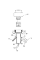
以上のことを前提として、前述した各管路13〜16が接続されるバルブケーシング40の構成を図1に示す。バルブケーシング40には、制御バルブ12が着脱可能に装着される。バルブケーシング40には各管路への接続部として、給液管路13が接続される第1のポート41,給気管路14が接続される第2のポート42,送液管路14が接続される第3のポート43及び送気管路16が接続される第4のポート44が設けられている。
【0016】
図1から明らかなように、第3のポート43への送液管路15の接続は、斜め上方に向けてであり、また第4のポート44への送気管16は真上に向けて接続されている。これらに対して、給液管路13の第1のポート41への接続及び給気管路14の第2のポート42への接続は、バルブケーシング40の側面において、このバルブケーシング40の軸線と直交する方向に接続されている。この接続形態は、制御バルブ12との相対関係で定まるものである。ここで、前述した第1〜第4のポート41〜44において、第3,第4のポート43,44は、送液管路15及び送気管路16の口径と概略一致している。これに対して、第1,第2のポート41,42は、バルブケーシング40の外面側の口径は給液管路13及び給気管路14とほぼ同径で、内部側に向けて連続的に縮径された絞り構造となっている。従って、これら第1,第2のポート41,42は流路の絞り部として機能する。そして、これら第1,第2のポート41,42の最も流路断面積が小さい部位は、それぞれ送液管路14及び送気管路16の内径とほぼ同じか、またはそれらより多少大きい口径を有するものとなっている。
【0017】
供給制御装置10より上流側に位置する給液管路13及び給気管路14は、洗浄用流体の供給時における圧損をできるだけ小さくするために、管路径を大きくしているが、下流側である送液管路15及び送気管路16と同じか、またはそれらより大きくなっているので、このように第1,第2のポート41,42を絞り部としたとしても、それらを給液管路13及び給気管路14と同じ径とした場合と比較して、実質的に圧力損失は生じない。
【0018】
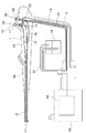
ここで、第1,第2のポート41,42を絞り形状としたのは、観察窓洗浄用流体供給機構自体の洗浄性を高めるためである。即ち、図2に示したように、管路13〜16の洗浄時には、制御バルブ12をバルブケーシング40から脱着して、代わりに洗浄アダプタ50をこのバルブケーシング40内に装着する。洗浄アダプタ50は、バルブケーシング40側から挿入部2の先端方向に洗浄ブラシを挿入するためのガイドとするものである。そして、この洗浄アダプタ50は、耐熱性,耐薬品性等の観点から、例えばポリエーテルイミド樹脂等の金属より軟質な樹脂材で形成される。つまり、洗浄アダプタ50はバルブケーシング40より柔らかい部材となっている。
【0019】
この洗浄アダプタ50には、それがバルブケーシング40に装着されたときに、斜め上方に接続されている送気管路16の延長方向に、この送気管路16の内径とほぼ一致する孔径の貫通路51が形成されている。また、バルブケーシング40の下面部に接続されている送液管路15の延長方向となるように接続パイプ52が洗浄アダプタ50に取り付けられており、この接続パイプ52はバルブケーシング40の表面とは非接触状態となるようにして上方に導かれている。そして、貫通路51及び接続パイプ52は洗浄アダプタ50の上面に開口している。また、洗浄アダプタ50は、バルブケーシング40の途中位置まで挿入されるものであり、その下端位置はバルブケーシング40の側面に形成した第1,第2のポート41,42の開口位置より上方となっている。そして、洗浄アダプタ50の底面部にはこれら第1,第2のポート41,42の開口部と所定の間隔を置いて、それらより下方に延在させた比較的肉厚の薄いストッパ部53が連設されている。
【0020】
ここで、観察窓洗浄用流体供給機構の本来の機能、つまり挿入部2の先端に設けた観察窓の洗浄機能については、前述した従来技術のものと格別の差異はない。従って、その説明は省略する。
【0021】
而して、内視鏡の使用後における観察窓洗浄用流体供給機構自体の洗浄性を向上させている。しかも、管路13,14の内部をブラッシングする洗浄用のブラシ60の保護が図られるようになっている。
【0022】
洗浄ブラシ60は、図5に示したように、ワイヤ61の先端部分またはほぼ全長にわたって多数の刷毛62を植設したものから構成される。この洗浄ブラシ60は給液管路13及び給気管路14にあっては、ユニバーサルコード3の先端側から挿入される。これに対して、送液管路15及び送気管路16にあっては、洗浄アダプタ50に設けた接続パイプ52及び貫通路51から挿入部2におけるノズル17の方向に向けて挿入される。
【0023】
前述した管路13〜16は曲げ方向に可撓性のある樹脂チューブで形成されているので、ワイヤ61は比較的柔軟なもので形成することによって、ワイヤ61で管路13〜16の内面に傷が付かないようにしている。従って、ワイヤ61の先端が硬質部材に強力に押し付けられると、曲折してしまう等、比較的脆弱なものとなっている。
【0024】
管路15,16によるブラシ洗浄は洗浄アダプタ50側から行われるが、給液管路13や給気管路14にあっては、ユニバーサルコード3側から挿入されて、第1、第2のポート41,42まで完全にブラッシングしなければならない。そして、これら第1,第2のポート41,42はバルブケーシング40の軸線と概略直交する方向に開口しているので、洗浄ブラシ60をそのまま真直ぐ導いたのでは、バルブケーシング40の内面に押し付けられて、ワイヤ61の先端部分が曲がってしまう等の問題点が生じることになる。
【0025】
しかしながら、内径の大きな給液管路13及び給気管路14内に挿入された洗浄ブラシ60は、そのバルブケーシング40の接続部を構成し、絞り構造となっている第1,第2のポート41,42に到る。従って、この第1,第2のポート41,42内に洗浄ブラシ60が入り込むと、洗浄ブラシ60の押し込み抵抗が増大することになり、この洗浄ブラシ60を操作する者に対して操作感触として、洗浄ブラシ60の先端が給液管路13及び給気管路14から第1,第2のポート41,42に移行したことを認識させることができる。しかも、これら第1,第2のポート41,42を通過する際には、抵抗の増大により押し込み速度が低下することになり、かつこれらのポート41,42の前方にはバルブケーシング40の内面が位置しているのではなく、それより柔軟な部材からなる洗浄用アダプタ50のストッパ部53が位置している。従って、前述した抵抗の増大を操作感触として与えられているにも拘らず、洗浄ブラシ60に、変形や損傷等を与えるような荷重が作用することはない。
【0026】
以上によって、各管路13〜16の洗浄を容易に行なうことができ、かつ作業時における洗浄ブラシ60の損傷を防止できることになる。
【0027】
【発明の効果】
洗浄用流体の管路をブラシ洗浄する際に、洗浄ブラシの先端がバルブケーシングに衝突するのを防止乃至抑制できる等の効果を奏する、
【図面の簡単な説明】
【図1】本発明の実施の一形態を示す供給制御装置への各管路の接続構造を示す断面図である。
【図2】各管路からバルブケーシングに至る経路の洗浄を行なっている状態を示す作用説明図である。
【図3】一般的な内視鏡の観察窓洗浄用流体供給機構の概略構成図である。
【符号の説明】
1 本体操作部 2 挿入部
10 供給制御装置 12 制御バルブ
13 給液管路 14 給気管路
15 送液管路 16 送気管路
40 バルブケーシング
41 第1のポート 42 第2のポート
43 第3のポート 44 第4のポート
50 洗浄アダプタ 51 貫通路
52 接続パイプ 53 ストッパ部
60 洗浄ブラシ 61 ワイヤ
62 刷毛[0001]
BACKGROUND OF THE INVENTION
According to the present invention, when the observation window provided at the distal end portion of the insertion portion of the endoscope is soiled, the cleaning fluid is supplied to the observation window and the cleaning fluid is supplied. In particular, the cleaning fluid supply mechanism for the endoscope observation window can be cleaned with a cleaning brush when the cleaning fluid supply mechanism is soiled. It is about.
[0002]
[Prior art]
The endoscope is provided with an illumination window and an observation window at the distal end of the insertion portion, and the observation window is contaminated with body fluids, so the observation window must be able to be cleaned appropriately. For this purpose, the endoscope includes an observation window cleaning fluid supply mechanism. A schematic configuration of this fluid supply mechanism is shown in FIG. In the figure, 1 is a main body operation unit, 2 is an insertion unit, and 3 is a universal cord. An illumination window and an observation window (not shown) are provided at the distal end of the
[0003]
Since the cleaning liquid and the pressurized air are not supplied at the same time, the cleaning liquid is supplied first, and then the pressurized air is supplied. Therefore, the cleaning fluid
[0004]
On the other hand, the
[0005]
The
[0006]
When the
[0007]
In addition to the observation window cleaning fluid supply mechanism described above, the endoscope also includes a suction mechanism from the body cavity. This suction mechanism uses the treatment
[0008]
[Problems to be solved by the invention]
By the way, the endoscope must be cleaned and disinfected each time it is used. In addition to the outer surface of the entire endoscope including the
[0009]
Here, the
[0010]
The present invention has been made in view of the above points, and the object of the present invention is to prevent the tip of the cleaning brush from colliding with the valve casing when the cleaning fluid conduit is brush cleaned. It is to be able to suppress.
[0011]
[Means for Solving the Problems]
In order to achieve the above-described object, the present invention provides a pipe that is attached to a main body operation unit of an endoscope and that is provided for cleaning an observation window, and includes an observation window side pipe and a supply source side pipe. A control valve that controls supply of the cleaning fluid supplied from the supply source side pipe line to the observation window side pipe line is attached to the connected valve casing, and the observation window side pipe line and the supply In the source side pipe, the inner diameter of the source side pipe is increased, and the diameter of the connection portion of the source side pipe to the valve casing is not smaller than the inner diameter of the observation window side pipe. It is characterized by having a configuration for forming a throttle portion of the road.
[0012]
DETAILED DESCRIPTION OF THE INVENTION
Hereinafter, an embodiment of the present invention will be described with reference to the drawings. Thus, the overall configuration of the observation window cleaning fluid supply mechanism in the endoscope is not particularly different from that of the above-described prior art. Therefore, in the following description, the same or equivalent members as shown in FIG. 3 are denoted by the same reference numerals, and the description thereof is omitted.
[0013]
Here, the
[0014]
In view of the above, the inner diameters of the
[0015]
On the premise of the above, FIG. 1 shows the configuration of the
[0016]
As is clear from FIG. 1, the connection of the
[0017]
The
[0018]
Here, the reason why the first and
[0019]
When the cleaning
[0020]
Here, the original function of the observation window cleaning fluid supply mechanism, that is, the cleaning function of the observation window provided at the distal end of the
[0021]
Thus, the cleaning performance of the observation window cleaning fluid supply mechanism itself after use of the endoscope is improved. In addition, the cleaning
[0022]
As shown in FIG. 5, the cleaning
[0023]
Since the
[0024]
The brush cleaning by the
[0025]
However, the cleaning
[0026]
As described above, the
[0027]
【The invention's effect】
When cleaning the conduit of the cleaning fluid with the brush, the tip of the cleaning brush has an effect of preventing or suppressing the collision with the valve casing.
[Brief description of the drawings]
FIG. 1 is a cross-sectional view showing a connection structure of each pipe line to a supply control apparatus showing an embodiment of the present invention.
FIG. 2 is an operation explanatory view showing a state where a path from each pipe line to a valve casing is being cleaned.
FIG. 3 is a schematic configuration diagram of a fluid supply mechanism for cleaning an observation window of a general endoscope.
[Explanation of symbols]
DESCRIPTION OF
Claims (4)
前記観察窓側管路と前記供給源側管路とでは、供給源側管路の方の内径を大きくし、
この供給源側管路の前記バルブケーシングへの接続部の口径を前記観察窓側管路の内径以下とならない範囲で流路の絞り部を形成する
構成としたことを特徴とする内視鏡の観察窓洗浄用流体供給機構。A pipe line, which is attached to the main body operation unit of the endoscope and is provided for cleaning the observation window, is connected to the valve casing to which the observation window side pipe line and the supply source side pipe line are connected. In what is equipped with a control valve for controlling the supply of the cleaning fluid supplied from the observation window side conduit,
In the observation window side pipeline and the supply source side pipeline, the inner diameter of the source side pipeline is increased,
Observation of an endoscope characterized in that the throttle part of the flow path is formed in a range in which the diameter of the connection portion of the supply source side pipe line to the valve casing is not less than the inner diameter of the observation window side pipe line Window cleaning fluid supply mechanism.
Priority Applications (1)
| Application Number | Priority Date | Filing Date | Title |
|---|---|---|---|
| JP2002095862A JP4100019B2 (en) | 2002-03-29 | 2002-03-29 | Endoscope observation window cleaning fluid supply mechanism |
Applications Claiming Priority (1)
| Application Number | Priority Date | Filing Date | Title |
|---|---|---|---|
| JP2002095862A JP4100019B2 (en) | 2002-03-29 | 2002-03-29 | Endoscope observation window cleaning fluid supply mechanism |
Publications (2)
| Publication Number | Publication Date |
|---|---|
| JP2003290139A JP2003290139A (en) | 2003-10-14 |
| JP4100019B2 true JP4100019B2 (en) | 2008-06-11 |
Family
ID=29239168
Family Applications (1)
| Application Number | Title | Priority Date | Filing Date |
|---|---|---|---|
| JP2002095862A Expired - Fee Related JP4100019B2 (en) | 2002-03-29 | 2002-03-29 | Endoscope observation window cleaning fluid supply mechanism |
Country Status (1)
| Country | Link |
|---|---|
| JP (1) | JP4100019B2 (en) |
Cited By (2)
| Publication number | Priority date | Publication date | Assignee | Title |
|---|---|---|---|---|
| JPH0683918U (en) * | 1993-05-24 | 1994-12-02 | 小松ゼノア株式会社 | Engine cooling air intake device |
| US8350990B2 (en) | 2005-07-01 | 2013-01-08 | Panasonic Corporation | Liquid crystal display apparatus |
Families Citing this family (3)
| Publication number | Priority date | Publication date | Assignee | Title |
|---|---|---|---|---|
| JP4520141B2 (en) * | 2003-12-22 | 2010-08-04 | オリンパス株式会社 | Endoscope device |
| JP2005278821A (en) * | 2004-03-29 | 2005-10-13 | Pentax Corp | Conduit cleaning device for endoscope |
| GB2513643B (en) * | 2013-05-02 | 2017-03-22 | Cantel (Uk) Ltd | Medical accessory holder |
-
2002
- 2002-03-29 JP JP2002095862A patent/JP4100019B2/en not_active Expired - Fee Related
Cited By (2)
| Publication number | Priority date | Publication date | Assignee | Title |
|---|---|---|---|---|
| JPH0683918U (en) * | 1993-05-24 | 1994-12-02 | 小松ゼノア株式会社 | Engine cooling air intake device |
| US8350990B2 (en) | 2005-07-01 | 2013-01-08 | Panasonic Corporation | Liquid crystal display apparatus |
Also Published As
| Publication number | Publication date |
|---|---|
| JP2003290139A (en) | 2003-10-14 |
Similar Documents
| Publication | Publication Date | Title |
|---|---|---|
| JP5009541B2 (en) | Endoscope flow path merging structure | |
| JP2005253543A (en) | Water duct for endoscope | |
| JP4538680B2 (en) | Endoscope pipe connection structure | |
| JP4100019B2 (en) | Endoscope observation window cleaning fluid supply mechanism | |
| JP5855488B2 (en) | Endoscope | |
| WO2020203165A1 (en) | Endoscope | |
| JP3808246B2 (en) | Endoscope | |
| JP2004049699A (en) | Washing adapter for endoscope | |
| JP4953748B2 (en) | Endoscope water nozzle | |
| JPH05103752A (en) | Endoscope | |
| JP2980233B2 (en) | Endoscope | |
| JP5606815B2 (en) | Endoscope | |
| JPH08112247A (en) | Endoscope | |
| JPH0810216A (en) | Air feeding and water feeding device of endoscope | |
| JP3169439B2 (en) | Endoscope air / water switching device | |
| JPH04802Y2 (en) | ||
| JP3019689B2 (en) | Air / water supply channel connecting pipe of endoscope and method of assembling the same | |
| JP3769848B2 (en) | Endoscopic fluid device | |
| JPH076883Y2 (en) | Endoscope | |
| JPS62277935A (en) | Water feeder for endoscope | |
| JP3825541B2 (en) | Endoscope | |
| JP3379164B2 (en) | Endoscope air / water supply mechanism | |
| JP3411695B2 (en) | Endoscope brush insertion aid | |
| JP6655429B2 (en) | Medical equipment and medical system using the same | |
| JP2000245696A (en) | Method and device for cleaning duct of endoscope |
Legal Events
| Date | Code | Title | Description |
|---|---|---|---|
| A621 | Written request for application examination |
Free format text: JAPANESE INTERMEDIATE CODE: A621 Effective date: 20041222 |
|
| TRDD | Decision of grant or rejection written | ||
| A01 | Written decision to grant a patent or to grant a registration (utility model) |
Free format text: JAPANESE INTERMEDIATE CODE: A01 Effective date: 20080226 |
|
| A61 | First payment of annual fees (during grant procedure) |
Free format text: JAPANESE INTERMEDIATE CODE: A61 Effective date: 20080310 |
|
| FPAY | Renewal fee payment (event date is renewal date of database) |
Free format text: PAYMENT UNTIL: 20110328 Year of fee payment: 3 |
|
| R150 | Certificate of patent or registration of utility model |
Free format text: JAPANESE INTERMEDIATE CODE: R150 |
|
| S111 | Request for change of ownership or part of ownership |
Free format text: JAPANESE INTERMEDIATE CODE: R313113 |
|
| FPAY | Renewal fee payment (event date is renewal date of database) |
Free format text: PAYMENT UNTIL: 20110328 Year of fee payment: 3 |
|
| R350 | Written notification of registration of transfer |
Free format text: JAPANESE INTERMEDIATE CODE: R350 |
|
| FPAY | Renewal fee payment (event date is renewal date of database) |
Free format text: PAYMENT UNTIL: 20110328 Year of fee payment: 3 |
|
| FPAY | Renewal fee payment (event date is renewal date of database) |
Free format text: PAYMENT UNTIL: 20120328 Year of fee payment: 4 |
|
| FPAY | Renewal fee payment (event date is renewal date of database) |
Free format text: PAYMENT UNTIL: 20120328 Year of fee payment: 4 |
|
| FPAY | Renewal fee payment (event date is renewal date of database) |
Free format text: PAYMENT UNTIL: 20130328 Year of fee payment: 5 |
|
| FPAY | Renewal fee payment (event date is renewal date of database) |
Free format text: PAYMENT UNTIL: 20130328 Year of fee payment: 5 |
|
| FPAY | Renewal fee payment (event date is renewal date of database) |
Free format text: PAYMENT UNTIL: 20140328 Year of fee payment: 6 |
|
| R250 | Receipt of annual fees |
Free format text: JAPANESE INTERMEDIATE CODE: R250 |
|
| LAPS | Cancellation because of no payment of annual fees |