JP4099570B2 - Digital recording / reproducing device - Google Patents
Digital recording / reproducing device Download PDFInfo
- Publication number
- JP4099570B2 JP4099570B2 JP2002106965A JP2002106965A JP4099570B2 JP 4099570 B2 JP4099570 B2 JP 4099570B2 JP 2002106965 A JP2002106965 A JP 2002106965A JP 2002106965 A JP2002106965 A JP 2002106965A JP 4099570 B2 JP4099570 B2 JP 4099570B2
- Authority
- JP
- Japan
- Prior art keywords
- format
- field
- basic
- frequency
- audio data
- Prior art date
- Legal status (The legal status is an assumption and is not a legal conclusion. Google has not performed a legal analysis and makes no representation as to the accuracy of the status listed.)
- Expired - Fee Related
Links
Images


Abstract
Description
【0001】
【発明の属する技術分野】
本発明はあるフィールド周波数に対応したオーディオデータやビデオデータの記録再生装置が存在する時に、そのシステムを基本として異なるフィールド周波数に対応する記録再生装置を作る際に、装置を簡素化する方式に関する。例えば、VTR記録再生装置のオーディオ部分やビデオ部分を簡素化する方式に関する。但し、本発明は、VTRに限られるものではない。
【0002】
【従来の技術】
VTR記録再生装置は、複数の異なるテレビジョンスタンダードの信号を記録、再生する為に、例えば日本、米国、欧州のそれぞれのHDTV方式に対応が可能なデジタル磁気記録再生装置が必要である。現在のテレビジョンよりも高精細な画像を提供するHDTVは、日本が世界に先がけて開発した。日本のHDTV方式はハイビジョンと呼ばれ走査線数が1125本、フィールド周波数が60Hzと決められている。一方、欧州及び米国では日本方式とは異なる方式のHDTVとなっている。例えば、欧州方式は、フィールド周波数が50Hzである。
【0003】
この様にテレビジョン方式が異なって、番組を制作したり、送出したりする機材がそれぞれに異なると、それぞれに個別の機材を開発し、製造しなければならないため、コストが高くなってしまう。又、他の方式で制作されたソフトを上映するためには、それぞれの方式に適合したVTRを用意し、別途設けたフォーマット変換装置で信号を変換した後、記録し直す必要があるため、手間も費用も重んでしまう。
【0004】
そもそも、VTRは制作や送出をする際の中心となる機材の1つであり、一般に放送用のVTRは高価であるため、異なるHDTV方式で共通のテープトランスポートや信号処理回路及びカセットやテープが使用できれば機器コストやランニングコストの低減と成るため使用者にとって利益が大きい。又、同じVTRで他の方式で記録したテープの再生が可能であれば各国間の番組変換が容易に低コストで行えるというメリットがある。
【0005】
【発明が解決しようとする課題】
しかるに従来の磁気記録再生装置では、異なるHDTV方式による高精細な画像とともに音声を、共通の機構で記録再生できる装置はなかった。異なる周波数に対応する装置を考える場合には異なる周波数それぞれ別々にフォーマットを作り、それぞれのフィールド周波数に対応する処理装置が必要であった。例えば60Field/s、50Field/sそれぞれの装置で共にオーディオ入出力サンプリング周波数が48KHz、サンプルあたりビット数24bitであった場合には60Field/sでは800sample/field×24bit/sampleでオーディオフォーマットを考えなければならないし、50Field/sでは960sample/field×24bit/sampleでオーディオフォーマットを考えなければならない。フィールドあたりの総ビット数は800×24=19200bit/fieldと960×24=23040bit/fieldと大きな差がある。よって、異なるフィールド周波数に対応する装置はそれぞれ全く違ったフォーマット、全く別の装置にならざるをえなかった。
【0006】
又,ビデオの画枠がそれぞれのフィールド周波数で違う。よって、異なるフィールド周波数に対応する装置はそれぞれ全く違ったフォーマット、全く別の装置にならざるをえなかった。
【0007】
そこで本発明は、あるフィールド周波数に対応する基本装置となるデジタル音声記録再生装置が存在する場合、異なるフィールド周波数のオーディオデータを基本装置のフォーマットに合うようにデータ変換し、適切な処理レートに変更することにより、基本装置を基に異なるフィールド周波数に対応する装置を実現することを目的とする。
【0008】
又本発明は、あるフィールド周波数に対応した基本装置となるデジタル映像記録再生装置が存在する場合、異なるフィールド周波数のビデオデータを基本装置のフォーマットに合うようにデータ変換し、適切な処理レートに変更することにより、基本装置を基に異なるフィールド周波数に対応する装置を実現することを目的とする。
【0009】
【課題を解決するための手段】
上述した従来の技術の課題を解決し、本発明の目的を達成する為に、以下の手段を講じた。即ち、本発明の第一面によれば、所定のサンプリング周波数及び固有フィールド周波数を有すると共に、固有のデータ配列及びビット配列をフィールド単位で規定する固有フォーマットに基づいたオーディオデータを受け入れ、少なくとも該オーディオデータのベースバンド処理を行う入力部と、所定のサンプリング周波数及び基本フィールド周波数を有し基本のデータ配列及びビット配列をフィールド単位で規定する基本フォーマットに基づいたオーディオデータを処理するように設計されており、サンプリング周波数に応じたクロックで動作し基本フォーマットに適合したオーディオデータのエラー訂正用の符号化処理を行う処理部と、該処理部から出力されたオーディオデータを記録媒体に書き込む出力部とからなるデジタル音声記録装置において、該入力部と該処理部との間に変換部が配されており、オーディオデータの固有フィールド周波数が基本フィールド周波数と異なり且つ固有フォーマットが基本フォーマットと異なる時、前記変換部は、固有フォーマットを基本フォーマットに適合させつつ、固有フィールド周波数と基本フィールド周波数との比に応じて該サンプリング周波数を変換してオーディオデータを該処理部に渡し、前記処理部は、該変換されたサンプリング周波数に応じたクロックで動作し、該基本フォーマットに適合したオーディオデータのエラー訂正用の符号化処理を行うことを特徴とする。具体的には、前記変換部は、一フィールド当りのサンプル数と一サンプルのビット数との積で決まる一フィールド当りの総ビット数を維持しつつ、一フィールド当りのサンプル数と一サンプルのビット数を組替えて固有フォーマットを基本フォーマットに適合させると共に、一フィールド当りのサンプル数を変えることで該サンプリング周波数を変換する。更に、一フィールド当りのサンプル数と一サンプルのビット数との積で決まる一フィールド当りの総ビット数が固有フォーマットと基準フォーマットで異なる場合、前記変換部は、入力されたオーディオデータのサンプリング周波数を変換して一フィールド当りのサンプル数を補正し、以って一フィールド当りの補正されたサンプル数と一サンプルのビット数との積で決まる一フィールド当りの補正された総ビット数を、基準フォーマットで決まる一フィールド当りの総ビット数に合わせる。或いは、一フィールド当りのサンプル数と一サンプルのビット数との積で決まる一フィールド当りの総ビット数が固有フォーマットと基準フォーマットで異なる場合、前記変換部は、不足するビット数に見合うダミーのデータを固有フォーマットに付加して一フィールド当りの総ビット数を補正し、以って固有フォーマット側の総ビット数を基準フォーマット側の総ビット数に合わせても良い。好ましくは、前記変換部は、シリアルに配列したサンプルのビットストリームからなるオーディオデータを固有フォーマット側のビット数単位でFIFOに書込み且つ基本フォーマット側のビット数単位で読出して、一フィールド当りのサンプル数と一サンプルのビット数を組替え固有フォーマットを基本フォーマットに適合させる。この場合、前記変換部は、固有フィールド周波数に同期して該FIFOに対するオーディオデータの書込み及び読出しを制御し、以って固有フォーマットを基本フォーマットに適合させる。
【0010】
一態様では、前記処理部は該変換部を変換手段として内蔵しているとともにオーディオデータのエラー訂正用の符号化処理を行なう符号化手段を含んでおり、オーディオデータの固有フィールド周波数が基本フィールド周波数と異なり且つ固有フォーマットが基本フォーマットと異なる時、前記変換手段は、固有フォーマットを変換し基本フォーマットに適合させた上でオーディオデータを該符号化手段に渡し、前記符号化手段は、所定のサンプリング周波数に応じたクロックで動作しつつ、固有フィールド周波数と基本フィールド周波数との比に応じた割合で随時休止を入れながら該基本フォーマットに適合されたオーディオデータのエラー訂正用の符号化処理を行う。具体的には、前記変換手段は、一フィールド当りのサンプル数と一サンプルのビット数との積で決まる一フィールド当りの総ビット数を維持しつつ、一フィールド当りのサンプル数と一サンプル当りのビット数を組替えて固有フォーマットを基本フォーマットに変換する。更に具体的には、前記変換手段は基本フォーマット側の一サンプル当りビット数に対応したビット数のレジスタを備え、シリアルに配列したサンプルのビットストリームからなる固有フォーマットのオーディオデータをサイクリックに該レジスタに書込む一方、固有フォーマット側の一サンプル当りビット数と基本フォーマット側の一サンプル当りビット数との比に応じた割合で随時休止を入れながら該レジスタからサイクリックにオーディオデータを読み出して、一フィールド当りのサンプル数と一サンプルのビット数を組替え固有フォーマットを基本フォーマットに変換する。
【0011】
本発明の第二面によれば、あるサンプリング周波数及び固有フィールド周波数を有すると共に、基本のデータ配列及びビット配列をフィールド単位で規定する基本フォーマットに適合されたオーディオデータを記録媒体から読込む入力部と、所定のサンプリング周波数及び基本フィールド周波数を有すると共に基本フォーマットに基づいたオーディオデータを処理するように設計されており、サンプリング周波数に応じたクロックで動作し基本フォーマットに適合したオーディオデータの少なくともエラー訂正用の復号化処理を行う処理部と、該処理部から出力されたオーディオデータの少なくともベースバンド処理を行った上で該オーディオデータを再生デバイスに供給する出力部とからなるデジタル音声再生装置において、前記処理部は、該読み込んだオーディオデータのサンプリング周波数に応じたクロックで動作可能であり、該基本フォーマットに適合したオーディオデータのエラー訂正用の復号化処理を行い、該処理部と該出力部との間に変換部が配されており、該読込んだオーディオデータの固有フィールド周波数が基本フィールド周波数と異なり且つ固有フォーマットが基本フォーマットと異なる時、前記変換部は、基本フォーマットに適合していた該オーディオデータを固有フォーマットに戻すと共に、固有フィールド周波数と基本フィールド周波数との比に応じて該読み込んだオーディオデータのサンプリング周波数を所定のサンプリング周波数に変換してオーディオデータを該出力部に渡すことを特徴とする。具体的には、前記変換部は、一フィールド当りのサンプル数と一サンプルのビット数との積で決まる一フィールド当りの総ビット数を維持しつつ、一フィールド当りのサンプル数と一サンプルのビット数を組替えて該オーディオデータを基本フォーマットから固有フォーマットに戻すと共に、一フィールド当りのサンプル数を変えることで該サンプリング周波数を変換する。尚、一フィールド当りのサンプル数と一サンプルのビット数との積で決まる一フィールド当りの総ビット数が固有フォーマットと基準フォーマットで異なる場合、前記変換部は、一旦該基本フォーマットから近似的に固有フォーマットに戻されたオーディオデータのサンプリング周波数を変換して一フィールド当りのサンプル数を補正し、以ってオーディオデータを最終的に固有フォーマットに変換する。或いは、一フィールド当りのサンプル数と一サンプルのビット数との積で決まる一フィールド当りの総ビット数が固有フォーマットと基準フォーマットで異なる場合、前記変換部は、一旦該基本フォーマットに適合したオーディオデータに余分のダミーデータを付加して近似的に固有フォーマットに戻した後、該ダミーデータを削除してオーディオデータを最終的に固有フォーマットに変換しても良い。好ましくは、前記変換部は、シリアルに配列したサンプルのビットストリームからなるオーディオデータを基本フォーマット側のビット数単位でFIFOに書込み且つ固有フォーマット側のビット数単位で読出して、一フィールド当りのサンプル数と一サンプルのビット数を組替え基本フォーマットを固有フォーマットに戻す。この場合、前記変換部は、固有フィールド周波数に同期して該FIFOに対するオーディオデータの書込み及び読出しを制御し、以って基本フォーマットを固有フォーマットに戻す。
【0012】
一態様では前記処理部は該変換部を変換手段として内蔵しているとともに、オーディオデータのエラー訂正用の復号化処理を行なう復号化手段を含んでおり、前記復号化手段は、所定のサンプリング周波数に応じたクロックで動作しつつ、固有フィールド周波数と基本フィールド周波数との比に応じた割合で随時休止を入れながら該基本フォーマットに適合したオーディオデータのエラー訂正用の復号化処理を行い、前記変換手段は、該読込んだオーディオデータの固有フィールド周波数が基本フィールド周波数と異なり且つ固有フォーマットが基本フォーマットと異なる時、基本フォーマットに適合していた該オーディオデータを固有フォーマットに戻した上でオーディオデータを該出力部に渡す。具体的には、前記変換手段は、一フィールド当りのサンプル数と一サンプルのビット数との積で決まる一フィールド当りの総ビット数を維持しつつ、一フィールド当りのサンプル数と一サンプルのビット数を組替えて該オーディオデータを基本フォーマットから固有フォーマットに戻す。更に具体的には、前記変換手段は、基本フォーマット側の一サンプル当りビット数に対応したビット数のレジスタを備え、固有フォーマット側の一サンプル当りビット数と基本フォーマット側の一サンプル当りビット数との比に応じた割合で随時休止を入れながら、シリアルに配列したサンプルのビットストリームからなる基本フォーマットのオーディオデータをサイクリックに該レジスタに書込む一方、固有フォーマット側の一サンプル当りビット数で区切りながら該レジスタからサイクリックにオーディオデータを読み出して、一フィールド当りのサンプル数と一サンプルのビット数を組替えて基本フォーマットを固有フォーマットに戻す。尚、オーディオデータの順方向再生と逆方向再生を切り替えて行う場合、前記変換手段は、該レジスタに対してオーディオデータの書き込み及び読み出しを行う時、一方ではビット列のMSBを先頭にし他方ではLSBを先頭にする。
【0013】
別の態様では、前記変換部は、一フィールド当りのサンプル数と一サンプルのビット数との積で決まる一フィールド当りの総ビット数を維持しつつ、一フィールド当りのサンプル数と一サンプルのビット数を組替えて該オーディオデータを基本フォーマットから固有フォーマットに戻す。この場合、更にシャトル再生制御部を備えており、異なるフィールドに属するオーディオデータを混合してシャトル再生を行う場合、該変換部で固有フォーマットに戻されたサンプルのうち正しいビット列を含む有効サンプルのみを該出力部に渡すことを特徴とする。好ましくは、前記シャトル再生制御部は、固有フォーマットに戻されたサンプルのうち正しいビット列を有さない無効サンプルに代えて、有効サンプルを補間して得られた代替サンプルを該出力部に渡す。又、前記シャトル再生制御部は、固有フォーマットに戻されたサンプルのうち正しいビット列と正しくないビット列を含んだ無効サンプルの少なくとも一部につき、正しくないビット列を0で置換して有効サンプルに転換し該出力部に渡す様にしても良い。
【0014】
本発明の第三面によれば、所定のサンプリング周波数及び固有フィールド周波数を有し画枠に関する固有フォーマットに基づいたビデオデータを受け入れ、少なくとも該ビデオデータのベースバンド処理を行う入力部と、所定のサンプリング周波数及び基本フィールド周波数を有し画枠に関する基本フォーマットに基づいたビデオデータを処理するように設計されており、サンプリング周波数に応じたクロックで動作し基本フォーマットに適合したビデオデータの圧縮処理及びエラー訂正用の符号化処理を行う処理部と、該処理部から出力されたビデオデータを記録媒体に書き込む出力部とからなるデジタル映像記録装置において、該入力部と該処理部との間に変換部が配されており、ビデオデータの固有フィールド周波数が基本フィールド周波数と異なる時、前記変換部は、固有フォーマットを基本フォーマットに適合させつつ、固有フィールド周波数と基本フィールド周波数との比に応じて該サンプリング周波数を変換してビデオデータを該処理部に渡し、前記処理部は、該変換されたサンプリング周波数に応じたクロックで動作し、該基本フォーマットに適合したビデオデータの圧縮処理及びエラー訂正用の符号化処理を行うことを特徴とする。具体的には、前記変換部は、固有フォーマットが基本フォーマットに一致する場合、該固有フォーマットを維持しつつ、固有フィールド周波数と基本フィールド周波数との比に応じ該サンプリング周波数を変換してビデオデータを該処理部に渡す。更に具体的には、前記変換部は、固有フォーマットが基本フォーマットに一致する場合、画枠に入る有効データをそのまま保存して該固有フォーマットを維持しつつ、画枠に入らない無効データを調整して該サンプリング周波数を変換する。又、前記変換部は、固有フォーマットが基本フォーマットと異なる場合、該固有フォーマットを該基本フォーマットに変換した上で、固有フィールド周波数と基本フィールド周波数との比に応じ該サンプリング周波数を変換してビデオデータを該処理部に渡す。具体的には、前記変換部は、固有フォーマットの画枠に含まれるデータのライン数が基本フォーマットの画枠に含まれるデータのライン数と異なる場合、該画枠に含まれるデータのライン数を調整して該固有フォーマットを該基本フォーマットに変換する。
【0015】
本発明の第四面によれば、あるサンプリング周波数及び固有フィールド周波数を有し画枠に関する基本フォーマットに適合されたビデオデータを記録媒体から読み込む入力部と、所定のサンプリング周波数及び基本フィールド周波数を有し基本フォーマットに基づいたビデオデータを処理するように設計されており、サンプリング周波数に応じたクロックで動作して基本フォーマットに適合したビデオデータのエラー訂正用復号化処理及び伸張処理を行う処理部と、該処理部から出力されたビデオデータの少なくともベースバンド処理を行った上で該ビデオデータを再生デバイスに供給する出力部とからなるデジタル映像再生装置において、前記処理部は、該読み込んだビデオデータのサンプリング周波数に応じたクロックで動作可能であり、該基本フォーマットに適合したビデオデータのエラー訂正用復号化処理及び伸張処理を行い、該処理部と該出力部との間に変換部が配されており、該読み込んだビデオデータの固有フィールド周波数が基本フィールド周波数と異なる時、前記変換部は、基本フォーマットに適合していた該ビデオデータを固有フォーマットに戻すと共に、固有フィールド周波数と基本フィールド周波数との比に応じて該読み込んだビデオデータのサンプリング周波数を所定のサンプリング周波数に変換してビデオデータを該出力部に渡す。具体的には、前記変換部は、固有フォーマットが基本フォーマットと同一である場合、該固有フォーマットを維持しつつ、固有フィールド周波数と基本フィールド周波数との比に応じサンプリング周波数を変換してビデオデータを該出力部に渡す。更に具体的には、前記変換部は、固有フォーマットが基本フォーマットと同一である場合、画枠に入る有効データをそのまま残して該固有フォーマットを維持しつつ、画枠に入らない無効データを調整してサンプリング周波数を変換する。又、前記変換部は、固有フォーマットが基本フォーマットと異なる場合、該基本フォーマットに適合していたビデオデータを該固有フォーマットに戻した上で、固有フィールド周波数と基本フィールド周波数との比に応じサンプリング周波数を変換してビデオデータを該出力部に渡す。例えば、前記変換部は、固有フォーマットの画枠に含まれるデータのライン数が基本フォーマットの画枠に含まれるデータのライン数と異なる場合、該画枠に含まれるデータのライン数を調整してビデオデータを該固有フォーマットにもどす。
【0016】
オーディオに関し本装置の記録側では、オーディオデータの変換部から記録再生媒体に近いブロックになるオーディオ処理部のクロックは基装置と対象装置のフィールド周波数比クロックを入力する。例えば、フィールド周波数60Field/s、オーディオ処理クロック周波数48KHzのVTRを基装置として、フィールド周波数50Field/sのVTRを考えた場合にはオーディオ処理クロック周波数を48KHz×50/60=40KHzとする。
【0017】
オーディオデータの変換部から装置の入力部に近い(媒体から遠い)ブロックのオーディオ処理クロックは装置の入力クロック周波数とする。例えば、基となる装置が60Field/sでオーディオデータが1フィールドあたり800Sample/field×24bit/Sample(サンプリング周波数48KHz)として、それを基とする50Field/sの装置では1フィールドあたり960Sample/field×20bit/Sample(サンプリング周波数48KHz)で記録する場合、オーディオデータの変換部から装置の入力部に近い(媒体から遠い)ブロックは共に48KHzのクロックで処理する。よって、両装置共にベースバンド処理は48KHzであり、共に同じ回路が使える。
【0018】
オーディオデータ変換部の装置入力部に近い側(媒体から遠い側)はオーディオデータのフィールドあたり総ビット数が、基となるフィールド周波数の装置と同じになるようなフィールドあたりサンプル数、サンプルあたりビット数にする。例えば、基となるフィールド周波数60Field/sの装置でオーディオが1フィールドあたり800Sample/field×24bit/Sampleで記録されているとしたら、フィールド周波数50Field/sの装置では960Sample/field×20bit/Sampleで記録する。共にフィールドあたり総ビット数は19200bit/sとなる。この例のようにサンプルあたりのビット数を基の装置より変えることによって共に装置の入力サンプリング周波数を同じにすることが出来る。上記例は両フィールド周波数装置共にサンプリング周波数48KHzである。
【0019】
上記のようにオーディオデータ変換部の装置入力部に近い側のフィールドあたりサンプル数、サンプルあたりビット数を決定するわけだが、これが装置入力部のフィールドあたりサンプル数、サンプルあたりビット数と同じであれば処理が簡単になる。しかし、対象フィールド周波数によっては都合の良いフィールドあたりサンプル数、サンプルあたりビット数がない場合がある。また、対象装置の都合によって、装置入力部のフィールドあたりサンプル数、サンプルあたりビット数を任意にしたい場合がある。この場合、装置入力部のフィールドあたりサンプル数、サンプルあたりビット数に近くて基装置の総ビット数と同じになるようなフィールドあたりサンプル数(サンプリング周波数に影響)、サンプルあたりビット数を決める。そしてそのサンプリング周波数になるように装置の入力部からオーディオデータ変換部までの間にオーディオサンプリングレートコンバータを設ける。例えば、基が60Field/sの装置でオーディオが1フィールドあたり800Sample/field×24bit/Sampleで記録できるとして、それを基にして48field/sの装置でオーディオ入力部を48KHzにする場合を考える。48field/sの装置ではオーディオが1000sample/fieldになる。単純に変換すると800sample/field×24bit/sample=19200bit/fieldであるので、1000sample/field×19.2bit/sampleとなる。1サンプルあたり19.2bitは整数ビット数ではないので実現できない。そこでこれに近くて都合の良いフィールドあたりサンプル数にする。例えば960sample/field×20bit/sampleにする。しかし、このフィールドあたりサンプル数ではサンプリング周波数が960sample/field×48field/s=46080sample/sとなる。そこで、装置の入力部とオーディオデータ変換部の間に46.08KHz<−>48KHzのサンプリングレートコンバータを設けて入力部は所望の48KHzサンプリングレートとする。この場合、46.08KHzにサンプリングレートコンバートされているが人間の可聴域は一般に20KHzなのでサンプリング定理にあてはめてもサンプリング周波数は40KHzを越えていれば良く、D/A、A/D等の性能を考えても46.08KHzのサンプリング周波数があれば十分であると考えられる。
【0020】
上記と同じ理由で都合の良いフィールドあたりサンプル数、サンプルあたりビット数がない場合に、サンプリングレートコンバータを使わずに、スタッフィング(意味のないデータ)を足して基となる装置と同じフィールドあたり総ビット数にしてもよい。例えば、フィールド周波数48Field/sを考えた場合、1000sample/field×19bit/sampleに200bitのスタッフィング(意味のないデータ)を足して800sample/field×24bit/sample=19200bit/fieldに変換する。
【0021】
本発明に係る音声記録装置では、オーディオデータのフォーマット変換処理をECCエンコード用の処理回路内にて行なうこともできる。オーディオデータのフォーマット変換をECCエンコード処理回路で行なうわけだが、ECCエンコード処理回路には、ベースバンド側に使うオーディオクロックのみを入力する。例えば、フィールド周波数60Field/s、ベースバンド側オーディオ処理クロック48KHzのVTRを基装置として、フィールド周波数50Field/s、ベースバンド側オーディオ処理クロック48KHzのVTRを作る場合にも、オーディオクロックは48KHzのみを入力する。48KHz×50/60=40KHzは必要ない。
【0022】
オーディオデータのフォーマット変換はECCエンコード処理回路への入力直後に行なう。オーディオデータの変換は、基となる記録装置のオーディオベースバンドサンプルあたりビット数分のレジスタを設けて、そのレジスタにLSBファストまたはMSBファストでサイクリックに書込み、読出しを行なうことで、オーディオデータのフォーマット変換を行なう。また、読出し側は書込み側データレートと合わせるために読出しの休みを入れる。例えば、フィールド周波数60Field/s、800sample/field×24bit/sampleを基とする装置に対してフィールド周波数50Field/s、960sample/field×20bit/sampleの装置を作る場合には、ECCエンコード処理回路で24個(24bit分)のレジスタを設け、そこでLSBファストに20bit/sampleでレジスタにサイクリックに書込み、LSBファストにて24bit/sampleでレジスタから読出し、オーディオデータのフォーマット変換を実現する。読出し側は6sampleに1回は読出しを休む。
【0023】
オーディオデータのフォーマット変換以降の回路へのコントロールは、オーディオデータのフォーマット変換用レジスタ読出しに応じて延びるようにする。つまり、オーディオデータのフォーマット変換用レジスタ読出しの休みに応じてコントロール信号のための内部カウンタ動作を休むようにする。例えばフィールド周波数60Field/sを基とする装置に対してフィールド周波数50Field/sの装置を作る場合には、6sampleに1sampleオーディオデータのフォーマット変換レジスタの読出しが休みになる。これに合わせてコントロール信号用内部カウンタも休む。よって、コントロール信号の周期は60Field/sの6/5の周期になり、60Field/sで800sample(1フィールド)で行なっていた処理が50Field/sでは960sample(1フィールド)かかって同じ処理をすることになる。
【0024】
一方、本装置の再生側では、オーディオデータ変換部から記録再生媒体に近いブロックのオーディオ処理部クロックは基装置と対象装置のフィールド周波数比クロックを入力する。例えば、フィールド周波数60Field/s、オーディオ処理クロック周波数48KHzのVTRを基装置として、フィールド周波数50Field/sのVTRを考えた場合にはオーディオ処理クロック周波数を48KHz×50/60=40KHzとする。
【0025】
オーディオデータ変換部から装置の出力部に近い(媒体から遠い)ブロックのオーディオ処理クロックは装置の出力クロック周波数とする。例えば、基となる装置が60Field/sでオーディオが1フィールドあたり800Sample/field×24bit/Sample(サンプリング周波数48KHz)として、それを基とする50Field/sの装置では1フィールドあたり960Sample/field×20bit/Sample(サンプリング周波数48KHz)で記録しているとすると、オーディオデータ変換部から装置の出力部に近い(媒体から遠い)ブロックは48KHzのクロックで処理する。よって、両装置共にベースバンド処理は48KHzであり、共に同じ回路が使える。
【0026】
オーディオデータ変換部の装置出力部に近い側(媒体から遠い側)はオーディオデータのフィールドあたり総ビット数が、基となるフィールド周波数装置と同じになるようなフィールドあたりサンプル数、サンプルあたりビット数にする。例えば、基となるフィールド周波数60Field/sの装置でオーディオが1フィールドあたり800Sample/field×24bit/Sampleで記録されているとしたら、フィールド周波数50Field/sの装置では960Sample/field×20bit/Sampleとする。共にフィールドあたり総ビット数は19200bit/sとなる。この例のようにサンプルあたりのビット数を基の装置より変えることによって共に装置の出力サンプリング周波数を同じにすることが出来る。上記例は両フィールド周波数装置共にサンプリング周波数48KHzである。
【0027】
上記のようにオーディオデータ変換部の装置出力部に近い側のフィールドあたりサンプル数、サンプルあたりビット数を決定するわけだが、これが装置出力部のフィールドあたりサンプル数、サンプルあたりビット数と同じであれば処理が簡単になる。しかし、対象フィールド周波数によっては都合の良いフィールドあたりサンプル数、サンプルあたりビット数がない場合がある。また、対象装置の都合によって、装置出力部のフィールドあたりサンプル数、サンプルあたりビット数を任意にしたい場合がある。この場合、装置出力部のフィールドあたりサンプル数、サンプルあたりビット数に近くて基装置の総ビット数と同じになるようなフィールドあたりサンプル数(サンプリング周波数に影響)、サンプルあたりビット数を決める。そしてそのサンプリング周波数になるように装置の出力部からオーディオデータ変換部までの間にオーディオサンプリングレートコンバーターを設ける。例えば、基が60Field/sの装置でオーディオが1フィールドあたり800Sample/field×24bit/Sampleで記録できるとして、それを基にして48field/sの装置でオーディオ出力部を48KHzにする場合を考える。48field/sの装置ではオーディオが1000sample/fieldになる。単純に変換すると800sample/field×24bit/sample=19200bit/fieldであるので、1000sample/field×19.2bit/sampleとなる。1サンプルあたり19.2bitは整数ビット数ではないので実現できない。そこでこれに近くて都合の良いフィールドあたりサンプル数にする。例えば960sample/field×20bit/sampleにする。しかし、このフィールドあたりサンプル数ではサンプリング周波数が960sample/field×48field/s=46080sample/sとなる。そこで、装置の出力部とオーディオデータ変換部の間に46.08KHz<−>48KHzのサンプリングレートコンバータを設けて出力部は所望の48KHzサンプリングレートとする。この場合、46.08KHzにサンプリングレートコンバートされているが人間の可聴域は一般に20KHzなのでサンプリング定理に当てはめてもサンプリング周波数は40KHzを越えていれば良く、D/A、A/D等の性能を考えても46.08KHzのサンプリング周波数があれば十分であると考えられる。
【0028】
上記と同じ理由で都合の良いフィールドあたりサンプル数、サンプルあたりビット数がない場合に上記のサンプリングレートコンバータを使わずに、スタッフィング(意味のないデータ)を足して基となる装置と同じフィールドあたり総ビット数にしても良い。例えば、フィールド周波数48Field/sを考えた場合、1000sample/field×19bit/sampleに200bitのスタッフィング(意味のないデータ)を足して800sample/field×24bit/sample=19200bit/fieldに変換する。
【0029】
データ記録におけるエンコード時には対象装置のオーディオデータをオーディオデータ変換部にてデータ変換を行ない、基となるフィールド周波数装置のベースバンドと同じフィールドあたりサンプル数、サンプルあたりビット数に変換すると同時にサンプリングレートをフィールド周波数比倍に変更する。具体的にはFIFOがデータ変換に利用でき、サンプリング周波数変換もFIFOで行なう。例えば、基となる装置が60Field/sでオーディオデータが1フィールドあたり800sample/field×24bit/Sampleとして、それを基とする50Field/sの装置では1フィールドあたり960sample/field×20bit/Sampleで記録する装置を考える。50Field/sの装置で6Sampleを1処理単位として6sample×20bit/sample(48KHz)をオーディオデータ変換部のFIFOに48KHzで書き込んで、FIFO上で5sample×24bit/sampleにデータ並び替えを行ない、40KHz(=48KHz×50/60)で読み出す。このようにすればオーディオデータ変換部で960sample/field×20bit/sample(48KHz)が800sample/field×24bit/sample(40KHz)に変換出来る。
【0030】
データ再生におけるデコード時にはオーディオデータ変換部にてデータ変換を行ない対象フィールド周波数装置に合ったフィールドあたりサンプル数、サンプルあたりビット数に変換すると同時にサンプリングレートをフィールド周波数比倍に変換して元にもどす。具体的にはFIFOがデータ変換に利用でき,サンプリング周波数変換もFIFOで行なう。例えば、基となる装置が60Field/sでオーディオデータが1フィールドあたり800Sample/field×24bit/Sampleとして、50Field/sの装置にて1フィールドあたり960Sample/field×20bit/Sampleを記録している場合を考える。媒体上では6sample×20bit/sample(48KHz)を5sample×24bit/sample(40KHz)に変換されて記録されている。再生された5sample×24bit/sample(40KHz)をオーディオデータ変換部のFIFOに40KHzで書き込んで、FIFO上で6sample×20bit/sampleにデータ並び替えを行ない、48KHzで読み出す。このようにすればオーディオデータ変換部で800sample/field×24bit/sample(40KHz)が960sample/field×20bit/sample(48KHz)に変換出来る。
【0031】
オーディオデータ変換のシーケンス起点はフィールド最初の第一サンプルからとする。例えば、上記の例だとエンコード時フィールド最初の第一サンプルから6sample×20bit/sampleが、変換処理で5sample×24bit/sampleに変換され、デコード時フィールド最初の第一サンプルから5sample×24bit/sampleが、変換処理で6sample×20bit/sampleに変換される。
【0032】
媒体上のオーディオ記録フォーマットは基となる装置と同じにして、誤り訂正符号化等の処理を基となる装置と全く同じに処理する。例えば基の装置が60Field/sでオーディオデータが1フィールドあたり800Sample/field×24bit/Sampleとして、それを基とした50Field/sの装置にて1フィールドあたり960Sample/field×20bit/Sampleで記録する場合、オーディオデータは変換部で960sample/field×20bit/sampleから800sample/field×24bit/sampleに変換される。変換後のオーディオデータは基となる装置と同じフィールドあたりサンプル数、サンプルあたりビット数であり、これに基となる装置と同じ誤り訂正等の処理をして、オーディオ記録フォーマットは基の装置と同じになるようにして記録する。
【0033】
本発明に係る音声記録装置では、オーディオデータのフォーマット変換処理をECCデコード処理回路内にて行なうこともできる。その際、ECCデコード処理回路にはベースバンド側に使うオーディオクロックのみを入力する。例えば、フィールド周波数60Field/s、ベースバンド側オーディオ処理クロック周波数48KHzのVTRを基装置として、フィールド周波数50Field/s、ベースバンド側オーディオ処理クロック周波数48KHzのVTRを作る場合にも、オーディオクロックは48KHzのみを入力する。48KHz×50/60=40KHzは必要ない。
【0034】
オーディオデータのフォーマット変換はECCデコード処理回路の出力直前に行なう。オーディオデータの変換は、基となる再生装置のオーディオベースバンドサンプルあたりビット数分のレジスタを設けて、そのレジスタにLSBファストまたはMSBファストでサイクリックに書込み、読出しを行なうことでオーディオデータのフォーマット変換を行なう。また、書込み側は読出し側データレートと合わせるために書込みの休みを適宜入れる。例えば、フィールド周波数60Field/s、800sample/field×24bit/sampleを基とする装置に対してフィールド周波数50Field/s、960sample/field×20bit/sampleの装置を作る場合にはECCデコード処理回路で24個(24bit分)のレジスタを設け、そこでLSBファストに24bit/sampleでレジスタにサイクリックに書込み、LSBファストにて20bit/sampleでレジスタから読出し、オーディオデータのフォーマット変換を実現する。書込み側は6sampleに1回は書込みを休む。
【0035】
オーディオデータのフォーマット変換より前の部分の回路へのコントロールはオーディオデータのフォーマット変換用レジスタ書込みの休みに応じて延びるようにする。つまり、オーディオデータのフォーマット変換用レジスタ書込みの休みに応じてコントロール信号用の内部カウンタ動作を休むようにする。例えばフィールド周波数60Field/sを基とする装置に対してフィールド周波数50Field/sの装置を作る場合には6sampleに1sampleオーディオデータのフォーマット変換レジスタの書込みが休みになる。これに合わせてコントロール信号用内部カウンタも休む。よって、コントロール信号の周期は60Field/sの6/5の周期になり、60Field/sで800sample(1field)で行なっていた処理が50Field/sでは960sample(1field)かかって同じ処理をすることになる。
【0036】
順方向再生の時と逆方向再生の時でオーディオデータのフォーマット変換用レジスタに読み書きする際にLSBファストとするか、MSBファストとするかを自動的に選択動作する。これは順方向再生と逆方向再生でオーディオデータが来る順番が逆になるため、フォーマット変換もMSBファスト詰め、LSBファスト詰めで逆になる。よって、オーディオデータのフォーマット変換も順方向再生、逆方向再生に応じてMSBファストでフォーマット変換するか、LSBファストでフォーマット変換するかを適宜コントロールする必要が出てくる。
【0037】
シャトル再生時にはオーディオデータのフォーマット変換処理をする際、異フィールドのデータが混じり合ってデータが再生されるが、オーディオデータのフォーマット変換シーケンスの最初と最後のデータパックには元の1サンプル分、全てのデータが入っているパックが来るはずなので、この元のデータにフォーマット変換出来るデータだけを有効データとして再生する。オーディオデータのフォーマット変換シーケンスの最初と最後以外のデータは完全にはフォーマット変換出来ず、違うサンプルデータが混じり合ってフォーマット変換されるはずであり、これらサンプルはエラーとして、後段でコンシール処理をする。尚、上位の有効データビット数を制限すればオーディオデータフォーマット変換シーケンスの最初と最後以外にも有効なオーディオデータフォーマット変換サンプルが出来るので上記よりも多くのデータを有効データとしてシャトル再生音に使える。但し、その場合には制限ビット数以下のLSBビットは0データに置き換える。
【0038】
ビデオに関しては本装置の記録側では、変換部で対象フィールド周波数の入力信号のビデオ画枠を基となる装置の画枠と同じになるように変換すると同時に、クロックをフィールド周波数比倍に変換する。例えば、基となる装置がフィールド周波数60field/sで2200sample/Line×1125Line/Field(有効領域1920sample×1080Line、クロック74.25MHz)だとして、対象となる装置がフィールド周波数50field/s、2640sample/Line×1125Line/Field(有効領域1920sample×1080Line、クロック74.25MHz)だとすると、変換部で対象となる装置の2640sample/Line×1125Line/Field(有効領域1920sample×1080Line,クロック74.25MHz)を2200sample/Line×1125Line/Field(有効領域1920sample×1080Line、クロック61.875MHz(=74.25MHz×50/60))に変換する。
【0039】
ビデオ圧縮処理や、誤り訂正符号化等のビデオエンコード処理は、変換部より先では基装置と対象装置のフィールド周波数比倍のクロックで基装置と全く同じ処理を行ない、記録フォーマットは基装置と同じになるようにする。例えば、基装置がフィールド周波数60field/s、ビデオ圧縮処理出力クロック46.4MHzで対象装置が50field/sだとすると、対象装置のビデオ圧縮処理出力クロックは46.4MHz×50/60=38.6666MHzで基装置と同じ処理を行なう。
【0040】
一方、本装置の再生側では、誤り訂正処理やビデオ伸張等のビデオデコード処理は、ビデオデコードクロック変換部までは基装置と対象装置のフィールド周波数比倍のクロックで基装置と全く同じ処理を行なう。例えば、基装置がフィールド周波数60field/s、ビデオ伸張入力クロック46.4MHzで対象装置が50field/sだとすると対象装置のビデオ伸張入力クロックは46.4MHz×50/60=38.6666MHzで基装置とまったく同じ処理を行なう。
【0041】
ビデオデコードクロックの変換部で対象フィールド周波数の出力信号のビデオ画枠を所望の画枠に変換すると同時に所望のクロックに変換する。例えば、基となる装置がフィールド周波数60field/sで2200sample/Line×1125Line/Field(有効領域1920sample×1080Line、クロック74.25MHz)だとして、対象となる装置の出力がフィールド周波数50field/s、2640sample/Line×1125Line/Field(有効領域1920sample×1080Line、クロック74.25MHz)だとすると、ビデオデコードクロック変換部の入力側では、基装置と同じ画枠かつクロックは基装置と対象装置のフィールド周波数比倍なので、2200sample/Line×1125Line/Field(有効領域1920sample×1080Line、クロック61.875MHz(=74.25MHz×50/60))になっている。これを対象となる装置の2640sample/Line×1125Line/Field(有効領域1920sample×1080Line、クロック74.25MHz)に変換する。
【0042】
標準規格(SD)等のようにフィールド周波数によってビデオライン数や有効画枠が違う場合には、記録側では対象装置のエンコード系にビデオライン数及び有効画枠等を基装置と同じにし且つクロックを基装置と対象装置のフィールド周波数比倍になるように変換するビデオラインコンバートフィルタ付きの変換部を設ける。例えばフィールド周波数60field/sで有効領域720sample×480Line(13.5MHz)、50field/sで有効領域720sample×576Line(13.5MHz)と、画枠及びクロックが違う場合を考える。これに対応するためには、50field/sの720sample×576Lineを60field/sの720sample×480Lineにフィルタ処理でライン変換し、かつクロック周波数を13.5MHz×50/60=11.25MHzに変換する。
【0043】
一方再生側では、標準規格(SD)等のようにフィールド周波数によってビデオライン数、有効画枠が違う場合には、対象装置のデコード系に基装置と同じビデオ画枠で且つクロックが基装置と対象装置のフィールド周波数比となっているビデオ信号を、所望のビデオ画枠及びクロック周波数に変換するビデオラインコンバートフィルタ付き変換部を設ける。例えば、基となる装置がフィールド周波数60field/sで有効領域720sample×480Line(13.5MHz)だとして、対象となる装置の出力がフィールド周波数50field/s、720sample×576Line(13.5MHz)だとすると、ビデオラインコンバートフィルタ付き変換部の入力側では基装置と同じ画枠で且つクロックが基装置と対象装置のフィールド周波数比倍なので、720sample×480Line(クロック11.25MHz(=13.5MHz×50/60))になっている。これを対象となる装置の720sample×576Line(13.5MHz)にビデオフィルタ付き変換部で変換する。
【0044】
【発明の実施の形態】
当発明はあるフィールド周波数の記録再生装置が存在する時に、そのシステムを基本として異なるフィールド周波数に対応する記録再生装置を作る際に、装置を簡素化する方式である。具体的な例としてVTR記録再生装置を例にあげるのでこれより先は記録再生装置という呼び方はせず、単にVTRと記述する。但し、本発明は、VTRに限られるものではない。このVTRはCPUを内蔵しており、コンピュータプログラムを実行して、所定の手順からなる音声記録方法、音声再生方法、映像記録方法及び映像再生方法を実現する。このコンピュータプログラムは、ROM、ハードディスクその他の媒体に格納され、VTRに組み込まれる。VTRのCPUは、この媒体からコンピュータプログラムを読み出して、実行するようになっている。
【0045】
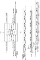
図1は、フィールド周波数60Field/sに対応したVTRのブロック図である。これが基本となるVTRになる。(A)は記録側を示し、(B)は再生側を示す。入力ビデオ信号はビデオベースバンド処理部1に送られる。ビデオベースバンド処理部1は、74.25MHzのクロックで動作する。ここで輝度、クロマ等がコントロールされる。ビデオベースバンド処理部1で処理された信号はビデオ圧縮部2に送られる。ここではビデオ信号が圧縮され、46.4MHzのクロックにのせられてECCエンコード&オーディオ/ビデオ結合部4に送られる。
【0046】
一方、入力オーディオ信号はサンプリング周波数が48KHzである。1フィールドあたりのサンプル数を計算すると48K/60=800sample/fieldとなる。1サンプルは24bitである。この入力オーディオ信号は、オーディオベースバンド処理部3に送られオーディオベースバンド処理が行われる。例えば、ここではゲイン調整等が行われる。オーディオベースバンド処理部3で処理された信号はECCエンコード&オーディオ/ビデオ結合部4に送られる。ECCエンコード&オーディオ/ビデオ結合部4ではオーディオ、ビデオそれぞれにエラー訂正コード(Error Correction Code、ECC)生成を行ない、C1,C2パリティーを付加して、テープフォーマットに合うようにデータ加工を行なう。ECCエンコード&オーディオ/ビデオ結合部4の入力クロックは、ビデオが46.4MHzで、オーディオが48KHz系である。また、出力はテープ記録データとして94MHzシリアルデータで出力される。
【0047】
ECCエンコード&オーディオ/ビデオ結合部4のオーディオ入力データはシリアルであり、1sample64bitで送られる。オーディオシリアルデータフォ−マットを図2に示す。ここでわかるようにシリアルデータは2チャネル混合のAES/EBUの形式で送られる。Z,M,J,E,V,U,C,Pはそれぞれフラグであり、本線データはLSBファストで送られてくる。図2は、24bit/sampleと20bit/sampleのデータ形式を示す。このように、ECCエンコード&オーディオ/ビデオ結合部4のオーディオ入力はシリアルデータである。図1では、48KHzと書いたがこれは1サンプルを1クロックと数えた時に48KHzのレートになるという意味であり、つまりサンプリング周波数のことである。ECCエンコード&オーディオ/ビデオ結合部4のオーディオ入力はシリアルデータなので、シリアルデータのクロック周波数で書くと48KHz×64bit/sample=3.072MHzとなる。しかしオーディオは1sampleを1単位とした周波数であるサンプリング周波数が重要であり、この例ではたまたま1sampleが64bitシリアルで送られてくるが、256bitで送られるという場合もありうる。このため、図1ではあえて重要な48KHzだけを記述しており、これより先もオーディオクロックについてはサンプリング周波数で記述する。
【0048】
ECCエンコード&オーディオ/ビデオ結合部4で作られた信号はテープに記録される。テープ再生された信号はECCデコード&オーディオ/ビデオ分離部5の入力となる。ECCデコード&オーディオ/ビデオ分離部5はオーディオ、ビデオのデータに分離した後、エラー訂正コードのデコード(復号化)を行ない誤り訂正を行なう。ビデオデータはクロック46.4MHzにのせて出力され、ビデオ伸張部6に入力される。ビデオ伸張部6では圧縮が解かれビデオベースバンド信号が出力される。この信号はビデオベースバンド処理部7に送られる。ビデオベースバンド処理部7では輝度、クロマ等がコントロールされた後、VTR出力される。一方オーディオはECCデコード&オーディオ/ビデオ分離部5で誤り訂正処理を行われた後、オーディオベースバンドでECCデコード&オーディオ/ビデオ分離部5より出力される。この時のフィールドあたりサンプル数、及びサンプルあたりビット数は800sample/field,24bit/sampleである。この信号がサンプリング周波数48KHzでオーディオベースバンド処理部8に送られる。オーディオベースバンド処理部8では出力オーディオのゲインコントロール等が行われる。この信号がVTR出力オーディオとなる。
【0049】
図3の(A)はフィールド周波数60Field/sのビデオ記録フォーマット図である。1フィールドは6トラックから構成されており、トラック1本でビデオ1ECC(エラー訂正コード)ブロック(積符合)が構成されている。6Track/Fieldであることから、ビデオは6ECCブロック/フィールドある。図3(A)のテープフットプリント図のVはビデオを表しており、ビデオは1トラックに2セクター分割されて置かれている。ビデオの1ECCブロックは250sync/trackであり、1セクターあたり125syncづつおかれており、2セクターで250Syncになる。つまり、1トラックでは250Syncデータが存在しており、このECCブロック構成は図3(B)のようになる。1SyncとはECCブロックのC1方向データ1本のことをいう。C1ECCパリティが12Byte,C2ECCパリティが24Byteの構成である。ビデオデータは圧縮データである。
【0050】
図4はフィールド周波数60Field/sのオーディオ記録フォーマット図である。図4(A)に示すテープフットプリント図のA0はオーディオチャネル0を表し、A1はオーディオチャネル1を表し、A2はオーディオチャネル2を表し、A3はオーディオチャネル3を表している。オーディオECCブロック構成はオーディオのチャネル毎に1フィールドで構成されている。オーディオは1トラック、1チャネルあたり4Syncづつ記録されている。よって、1フィールド分6トラックのデータを集めると4Sync/track・チャネル×6Track/Field=24Sync/field・チャネルとなり、これでオーディオ1チャネルのECCブロックを構成する。図4の(B)に示すようにオーディオECCブロックが構成され、C1ECCパリティは12Byte,C2ECCパリティは12Byteが割り当てられている。オーディオ1サンプルあたり24bitであるのでこれを8bit×3Symbolに分割する。図4(B)に示すように、1Sampleは同じSyncに3ByteのデータとしてMSBから入るように構成されている。1フィールドあたりでは800sampleのデータであるのでECCブロックで4Sample分データ枠が余るが、ここにはユーザデータが割り当てられている。オーディオサンプルデータは非圧縮のデータが入る。
【0051】
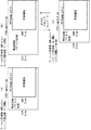
図5は、フィールド周波数50Field/sを実現するVTRのブロック図である。(A)は記録側を示し、(B)は再生側を示す。このVTRは図1のフィールド周波数60Field/sのVTRを基本としている。ビデオ圧縮部2、オーディオベースバンド処理部3、ECCエンコード&オーディオ/ビデオ結合部4、ECCデコード&オーディオ/ビデオ分離部5、ビデオ伸張部6及びオーディオベースバンド処理部8は、全て基本となる60Field/s対応のVTRと全く同じブロックを使用する。ビデオベースバンド処理部1’及びビデオベースバンド処理部7’はそれぞれビデオエンコード/デコードのベースバンド処理ブロックであるが、処理クロックが74.25MHzであり、基となるフィールド周波数60Field/sのビデオベースバンド処理部1及びビデオベースバンド処理部7の処理クロックと同じであり、ほとんど同じ処理が使えるので、実際にはビデオベースバンド処理部1’とビデオベースバンド処理部1、ビデオベースバンド処理部7’とビデオベースバンド処理部7には回路的な差異がほとんどない。
【0052】
ビデオクロックコンバータ11は、入力74.25MHzに対して出力がフィールド周波数比50/60倍の61.875MHzとなるようなクロックコンバータである。本例はハイビジョンを考えており、フィールド周波数50Hz,60Hzのいずれの場合にもビデオ有効フレーム領域が1920sample×1080Line(または1440sample×1080Line)という画枠であり、50Hz,60Hzで有効画枠の違いはないので単純に50/60倍の61.875MHzにしても無効領域を捨て去るだけであり、有効領域はすべてがそのまま有効データとなる。
【0053】
図6に各フィールド周波数及び処理過程における画枠の違いを示した。(A)はフィールド周波数60Hzの画枠、(B)はフィールド周波数50Hzの画枠、(C)はフィールド周波数50Hzの画枠をビデオクロックコンバータ11で処理した後の画枠(信号形態)を示す。このように、ビデオクロックコンバータ11で処理した後の信号形態(C)は無効領域も含めて60Field/s、74.25MHzの信号形態(A)と全く同じである。
【0054】
ビデオクロックコンバータ11から出力された61.875MHzの出力信号をビデオ圧縮部2に送る。出力クロックも50/60倍の38.666MHzとすれば、ビデオ圧縮部2にとってはクロックとデータレートが50/60倍になっただけであり、処理は基となる60Field/sVTRと全く同じである。逆の言い方をすればビデオクロックコンバータ11の役目はビデオクロックコンバータ11以降の処理を50/60倍のレートで基となる60Field/s対応VTRと全く同じ処理をさせることといえる。
【0055】
一方オーディオ側は、ビデオ側のビデオクロックコンバータ11と同じ働きを、オーディオデータパック部9で行なう。オーディオデータパック部9では、図5に書いているように48KHz,960sample/field×20bit/sample(=19200bit/field)を40KHz,800sample/field×24bit/sample(=19200bit/field)にデータ変換する。これらのオーディオデータはどちらもフィールドあたり総ビット数が19200bit/fieldと同じなのでデータ変換が可能である。ここで40KHz=48KHz×50/60であり、オーディオ側も、オーディオデータパック部9以降は50/60倍のレートで基となるフィールド周波数60field/sVTRと全く同じ処理が出来る。
【0056】
図7にオーディオデータパック部9の詳細構成を示す。図7の(A)でわかるように、オーディオデータパック部9はFIFOコントロールとFIFO部からなっている。データパックの1シーケンスは48KHz系(20bit/sample)で6sampleとなっている。20bit/sample×6sample=120bitであるが、これを40KHz系(24bit/sample)で120bit=24bit/sample×5sampleに変換する。オーディオデータパック部9にはオーディオデータがシリアルで入力されており、48KHz系の64×48KHzでシリアル1bitづつ書込む。この時、Z,M,J,E,V,U,C,PのフラグはFIFOに書かず、データだけをFIFOに書く。これを40KHz系の64×40KHzでシリアル1bitづつ読出しする。但し、フラグ部分はFIFOから読出しせずに0をうめる(後段でフラグは意味のないデータである)。読出しは24bitを1sampleとしてサンプル毎行ない、ECCエンコード&オーディオ/ビデオ結合部4に送られる。図7(B)にしめすようにシーケンスの開始点はフィールドの先頭で行なうこととする。このコントロール信号として、オーディオデータパック部9にはフィールド先頭を示す信号Field−Startがきている。図7(B)には、データパックのFIFOへの書込み及び読出しの様子が書いてある。ここでFIFOが4bitのマスで区切られているのは20bit−>24bit変換の様子を分かりやすくするためであり、実際には先に述べたように1bit毎に書込まれており、1bit毎に読出されている。Field−Startについては、48KHz系から40KHz系へ変換する時オーディオデータパック部9内のFIFOコントロールが信号Field−Startを出して、変換後の40KHz系でフィールド先頭がどこかということを示す情報を出す。この情報を基にしてECCエンコード&オーディオ/ビデオ結合部4においてオーディオのフィールド切れ目で区切ってオーディオデータ切り出しを行ないECCブロックを作る。
【0057】
図5に示した、ECCエンコード&オーディオ/ビデオ結合部4のビデオ入力及びオーディオ入力は、共に60Field/sの場合に比べて50/60倍のレートになっている。そして、ECCエンコード&オーディオ/ビデオ結合部4の出力も50/60倍のレートなので、ECCエンコード&オーディオ/ビデオ結合部4は60Field/sの場合と全く同じ処理を50/60倍のレートで処理することになる。当然ではあるが、回路等は60Field/sと50Field/sの場合で全く同じものが使える。そして、50/60倍のレートでテープに記録される。この時テープ走行速度、ドラム回転速度等は全て60Field/sの場合に比べてフィールド周波数比倍の50/60倍レートになっている。よって、フットプリントは基となるフィールド周波数60Field/s対応VTRと50Field/s対応VTRとで同じになる。
【0058】
一方テープ再生では、基本となるフィールド周波数60Field/sの50/60倍レートのデータがECCデコード&オーディオ/ビデオ分離部5に入力される。ECCデコード&オーディオ/ビデオ分離部5は全て60Field/sの50/60倍のレートで処理を行なう。このためビデオ出力及びオーディオ出力は共に60Field/sVTRの場合より50/60倍のレートとなる。当然ではあるが、ECCデコード&オーディオ/ビデオ分離部5は60Field/sの場合と全く同じ処理でレートが違うだけなので60Field/sと同じ回路が使える。ECCデコード&オーディオ/ビデオ分離部5のビデオ出力はビデオ伸張部6に入る。ビデオ伸張部6も入出力処理共に60Field/sの場合に比べて50/60倍のレートになる。当然回路は60Field/sの場合と全く同じものが使える。ここで,再生側のビデオクロックコンバータ12は、記録側のビデオクロックコンバータ11と逆の働きをする。ビデオクロックコンバータ12は、60Field/sの50/60のレートである61.875MHzから74.25MHzに戻す。図6に示すように有効領域は変化せず、無効領域(ブランキング部分)が増えて74.25MHzとなる。ビデオベースバンド処理部7’ではビデオベースバンド処理が行われ、輝度及びクロマ等の調整がされる。ビデオベースバンド処理部7’のフィールド周波数50Field/s出力がVTR出力となる。
【0059】
一方オーディオはECCデコード&オーディオ/ビデオ分離部5で誤り訂正処理がなされた後、40KHz,800sample/field×24bit/sampleでデータパックされた状態で、オーディオデータデパック部10に入力される。オーディオデータデパック部10では、オーディオデータパック部9と逆の働きをしてデータパックをほどき、元の48KHz,960sample/field×20bit/sampleに戻す。オーディオデータデパック部10の詳細を図8に示す。(A)に示すように,オーディオデータパック部9と同じようにFIFOコントロールで40KHzから48KHzへ変換されても、フィールド先頭を示す信号Field−Startが正しく伝わるようになっている。書込み側の信号Field−Startはデータデパックシーケンスの開始点であり、非常に重要な信号である。シーケンスは、オーディオデータパック部9と同じように40KHz系(書込み側)で5sample×24bit/sample=120bit、48KHz系(読出し側)で6sample×20bit=120bitが1シーケンスとなっている。オーディオデータデパック部10でも、信号Field−Startがデータデパックシーケンス開始点となっている。
【0060】
オーディオデータデパック部10で処理された48KHz,960sample/field×20bit/sampleはオーディオベースバンド処理部8に入力され、ゲイン調整等のオーディオベースバンド処理が行われた後、VTR出力として、フィールド周波数50Field/s,48KHz,960sample/field×20bit/sampleで出力される。このようにしてフィールド周波数60Field/sVTRを基として、フィールド周波数50Field/sに対応する。
【0061】
これまではフィールド周波数50Field/sの場合について述べたが、他のフィールド周波数についても対応可能である。図9にフィールド周波数48Field/sの場合のブロック図を示す。(A)は記録側を示し、(B)は再生側を示す。基となるVTRは図1のフィールド周波数60Field/sVTRである。ビデオ側はビデオクロックコンバータ11及びビデオクロックコンバータ12で先ほどのフィールド周波数50Field/sの場合と同様にレートをフィールド周波数比倍変換しており、この場合74.25MHz<−−−−>59.4MHz(=74.25MHz×48/60)に変換している。
【0062】
この様子を図10に示した。(A)はフィールド周波数60Hzの画枠、(B)はフィールド周波数48Hzの画枠、(C)はフィールド周波数48Hzの画枠をビデオクロックコンバータ11で処理した後の画枠(信号形態)を示す。図10を見てわかるように、フィールド周波数50Field/sの場合と同様に、有効領域は入力ビデオクロックコンバータ11及び出力ビデオクロックコンバータ12の変換でも変わらず、無効領域(ブランキング領域)だけが変化しているのがわかり、変換後は無効領域及び有効領域を含めて、基となる60Field/sVTRの画枠と全く同じになることがわかる。
【0063】
一方、オーディオを考えた時、基となるフィールド周波数60Field/sVTRとフィールド周波数48Field/sVTRにおいて、オーディオのフィールドあたり総ビット数が同じになるようにするわけだが、フィールド周波数48Field/sでは都合の良いフィールドあたりサンプル数、サンプルあたりビット数にならない。基となる60Field/sVTRでオーディオが1フィールドあたり800Sample/field×24bit/Sampleで記録できる。それを基にして48field/sVTRでオーディオ入力部を48KHzにする場合を考える。48field/sだから1000sample/fieldになる。単純に変換すると800sample/field×24bit/sample=19200bit/fieldであるので、1000sample/field×19.2bit/sampleとなる。1サンプルあたり19.2bitは整数ビット数ではないので実現できない。そこでこれに近い960sample/field×20bit/sampleを経由して800sample/field×24bit/sampleに変換する。図9にあるように一旦、オーディオレートコンバータ13で、1000sample/field×20bit/sample(48KHz、48Field/s)を960sample/field×20bit/sample(46.08KHz、48Field/s)に変換する。この信号をオーディオデータパック部9でデータ変換して800sample/field×24bit/sample(36.864KHz=46.08KHz×48/60,48Field/s)にする。フィールド周波数50Field/sの場合と同じように、フィールド周波数比レートでエンコード処理を行なう。
【0064】
デコード処理はエンコード処理と逆に行ない、オーディオデータデパック部10で800sample/field×24bit/sample(36.864KHz,48Field/s)を960sample/field×20bit/sample(46.08KHz,48Field/s)に変換し、オーディオレートコンバータ14で1000sample/field×20bit/sample(48KHz、48Field/s)に変換してVTR出力される。この際に46.08KHzにサンプリングレートがコンバートされているが、人間の可聴域は一般に20KHzなのでサンプリング定理にあてはめてもサンプリング周波数は40KHzを越えていれば良く、D/A、A/D等の性能を考えても46.08KHzのサンプリング周波数があれば十分であると考えられる。このように総ビット数が同じになるようなサンプルあたりビット数を単純に考えた場合に、整数ビットとならない場合でもサンプリングレートコンバータを用いることによりサンプリング周波数をそれほど落とさずにサンプルあたりビット数を整数ビットにすることができる。
【0065】
上記フィールド周波数48Field/sを考えた場合、上記方法のサンプリングレートコンバータを用いずに1000sample/field×19bit/sampleに200bitのスタッフィング(意味のないデータ)を足して800sample/field×24bit/sampleに変換してもよい。ただし、この場合にはオーディオデータパック/デパックシーケンスが長くなるので大きいFIFOが必要である。即ち,20ビットと24ビットの関係に比べ,19ビットと24ビットの数値関係では最小公倍数が高くなってしまい,その分FIFOのサイズが大きくなる。
【0066】
ここまではハイビジョンを例に説明をしてきたので、図6及び図10に示す例のようにフィールド周波数が違ってもハイビジョンの規格上有効領域の画枠が同じであり、図5のビデオクロックコンバータ11とビデオクロックコンバータ12でライン変換フィルタ処理はしない。しかしスタンダード規格(SD)の場合、有効領域の画枠は、フィールド周波数60Field/sでは720sample×480Line、フィールド周波数50Field/sでは720sample×576Lineとライン数が違っているので、ライン変換フィルタ処理が必要になる。図11に基となるスタンダード規格のフィールド周波数60Field/sVTRのブロック図を示す。(A)は記録側を示し、(B)は再生側を示す。オーディオベースバンド処理部3及びオーディオベースバンド処理部8は、図1の例と同じである。入力ビデオベースバンド処理部15、ビデオ圧縮部16、ECCエンコード&オーディオ/ビデオ結合部17、ECCデコード&オーディオ/ビデオ分離部18、ビデオ伸張部19及び出力ビデオベースバンド処理部20は、SD用の処理ブロックである。
【0067】
図12にフィールド周波数60Field/sVTRを基にしたSDフィールド周波数50Field/sVTRのブロック図を示す。(A)は記録側を示し、(B)は再生側を示す。また、図13にそれぞれの画枠及び、フィールド周波数50Field/sの処理後の画枠を示す。(A)はフィールド周波数60Hzの画枠、(B)はフィールド周波数50Hzの画枠、(C)はフィールド周波数50Hzの画枠をビデオクロックコンバータで処理した後の画枠(信号形態)を示す。図12において、ビデオベースバンド処理部21および24はそれぞれ入力ビデオベースバンド処理、出力ビデオベースバンド処理を行なうが、フィールド周波数50Field/s用のものであり、ライン数が違うためにフィールド周波数60Field/sに対応した図11のビデオベースバンド処理部15および20とは全く違った処理になる。図12のビデオライン&クロックコンバータ22が図5のビデオクロックコンバータ11にあたる部分であり、フィールド周波数50Field/sの有効画枠720sample×576Lineを、基となるフィールド周波数60Field/sの有効画枠720sample×480Lineに変換するライン変換フィルタ処理を行なっている。図13に示すように、ビデオライン&クロックコンバータ22で画枠を変換すると共にクロックも変更している。
【0068】
図12のビデオライン&クロックコンバータ23が、図5のビデオクロックコンバータ12にあたる部分であり、基となるフィールド周波数60Field/sの有効画枠720sample×480Lineをフィールド周波数50Field/sの有効画枠720sample×576Lineに変換するライン変換フィルタ処理を行い、元のライン数に戻している。図13に示すようにビデオライン&クロックコンバータ23で画枠を変換すると共にクロックも変更している。ハイビジョンの例と同様に、ビデオ圧縮部16、ECCエンコード&オーディオ/ビデオ結合部17、ECCデコード&オーディオ/ビデオ分離部18及びビデオ伸張部19はレートが変化するだけで、回路は基となるフィールド周波数60Field/sVTRと同じものが使える。また、オーディオはハイビジョンの例と同様に処理することが出来、オーディオデータパック部9、オーディオデータデパック部10、オーディオベースバンド処理部3及びオーディオベースバンド処理部8は図5のハイビジョンVTRと全く同じものである。SDの場合を例にあげて述べたが、このように画枠が違っても画枠を変換するフィルタ処理をかけることによって、基となるフィールド周波数VTRから違うフィールド周波数VTRを作ることができる。
【0069】
ここで、図5に示したVTRの発展形態を説明する。図5に示したフィールド周波数50Field/s対応VTRのオーディオデータデパック部10を、ECCデコード&オーディオ/ビデオ分離部5に内蔵化して、内部にその機能を持たせた構成であり、そのブロック図を図14に示す。(A)は記録側を示し、(B)は再生側を示す。図14はフィールド周波数60Field/s,50Field/sの両者に対応している共通VTRである。図14に記述している周波数で60Field/sと50Field/sそれぞれで値が違うものはフィールド周波数比倍の関係になっている。例えばビデオ圧縮部2の出力は38.6666MHz=46.4MHz×50/60とフィールド周波数比倍の関係になっている。
【0070】
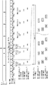
ECCエンコード&オーディオ/ビデオ結合部4’の具体的な構成を図15に示す。ここでビデオは、ビデオC2ECC処理部35でC2ECC処理されたものが、SDRAM読出/書込コントロール部31に送られる。一方オーディオは、シリアルデータがS/P変換部25でシリアル/パラレル変換され、そのデータがコントローラ26に送られる。コントローラ26はRateConvRAM書込みコントロール(RateConvRAM28のデータ書込みコントロール)とECCスタートコントロール(他のコントローラ29の処理スタートコントロール)を行なう。コントローラ26には、コンバートレジスタ34が入っている。この部分は後ろで詳しく説明する。RateConvRAM28はDualPortRAMであり、ここでオーディオ48KHz系クロックから内部システムクロック(66MHz)にクロックのせかえが行われる。コントローラ29はRCRAM(RateConvRAM28)の読出しコントロール、C2RAM30のコントロール、C2ECCパリティ付加処理、SDRAM書込み用のアドレス発生が行われる。SDRAM読出/書込コントロール部31は、SDRAM32のアクセスコントロールをしている。C1ECC処理部33は、SDRAM読出しアドレス発生とC1ECCパリティ付加を行なって、RFクロックレートにのせてRFデータを出力する。オーディオタイミングジェネレータ27は、フィールド信号及びサンプリング周期(FS)信号をもらい、1フィールドを数えている。この場合、フィールド周波数が60Field/s、50Field/s共にサンプリング周波数48KHzであるから、フィールド周波数60Field/sの場合には1フィールドあたり800sampleをカウンタで計数し、コントローラ26及びC1ECC処理部33に処理タイミングを与えており、フィールド周波数50Field/sの場合には1フィールドあたり960sampleをカウンタで計数しコントローラ26及びC1ECC処理部33に処理タイミングを与えている。
【0071】
図16にECCエンコード&オーディオ/ビデオ結合部4’のオーディオタイミングチャートを示す。図16はフィールド周波数60Field/s、1サンプルが24bit/sampleの処理について書かれている。つまりフィールド周波数50Field/sの場合、20bit/sampleを24bit/sampleに変換した後の処理タイミングが書かれている事になる。まず、基本となる60Field/sのタイミングについて述べる。RateConvRAM28は内部が3bankに分かれており、それぞれのbankに48sample×24bit/sampleのデータが格納できるようになっている。図16の数字はRCRAMbankNo.を示している。800sample/fieldを48sample/bank×16bank+32sample(1bank)で処理していることがわかる。オーディオデータがFS(サンプリング周波数48KHz)レートでRateConvRAM28に書かれる。Fld−Start(Field−Start)及びC2−Startはコントローラ26より来る処理タイミングコントロール信号であり、Fld−startから新しいフィールドデータがRateConvRAM28に書き込まれる。図16で新フィールドデータがbank2,0から順にRateConvRAM28に書かれていることがわかる。そして、次のC2−Startが来るとbank2,0のC2ECC処理を開始する。RateConvRAM28からシステムクロック66MHzでC2方向に読み出す。コントローラ29でC2ECC処理を行ない、C2パリティを付加した後にC2RAM30にC2方向に書込みされる。C2RAMすべてに書き終わるとC2RAMからC1方向に読み出し、SDRAM書込みアドレスと共にSDRAM読出/書込コントロール部31に送られ、SDRAM32に書かれる。このような処理をチャネル0から順にチャネル7まで時分割的に行なう。C2−StartはRateConvRAM28に2bank分が書込みされる毎に来て、フィールド最後はFld−start信号と同時にC2−Startがきて、カレントフィールドで残ったデータを処理する。フィールド最後は結果的には1bank分に満たない32sample分の処理を行なっている。Fld−Start及びC2−Startは、コントローラ26がオーディオタイミングジェネレータ27より入力されるコントロール信号から作っている。このようにしてフィールド周波数60Field/sのオーディオECCエンコード処理が行われる。基本となるフィールド周波数60Field/sでは、コンバートレジスタ34は使われない。
【0072】
次に、フィールド周波数50Field/sの信号が入力された場合について述べる。図14でわかるように、フィールド周波数50Field/s時にはECCエンコード&オーディオ/ビデオ結合部4’へのオーディオ入力は960sample/field×20bit/sample(48KHz)で来る。これをオーディオデータパックして800sample×24bit/sampleに変換するわけだが、オーディオデータパックの働きをするのは、図15のコンバートレジスタ34である。図15のS/P変換部25は960sample/field×20bit/sampleのデータをフィールド周波数60field/sと同様に処理してシリアル/パラレル変換する。S/P変換部25からコントローラ26へ来るパラレルデータはLSBファストで8bit単位に来る。20bit/sampleを送る時にはLSB4bit、MDB(中間)8bit及びMSB8bitに分割されて来る。これをコンバートレジスタ34で24bitデータに変換するわけだが、シーケンスの単位は960sample/field×20bit/sampleで6sampleを1シーケンスとしてこれを24bit、5sampleに変換する。すなわち、6sample×20bit/sampleを5sample×24bit/sampleに変換する。よって、960sample/field×20bit/sampleは800sample/field×24bit/sampleに変換されることになる。
【0073】
コンバートレジスタ34の動作説明図を図17に示す。コンバートレジスタ34には24個(24bit分)のレジスタがある。入力データは20bit/sampleであり、図17に示すように信号Field−Startを変換処理シーケンス先頭としてオーディオデータをレジスタにLSBファストで順にMSBの方に詰めて書込む。1サンプルデータはさきほど述べたように、LSB4bit、MDB8bit、MSB8bitの3つに分解されてくるので、レジスタにも1sampleを3つに分けて書込みしている。書込み時、レジスタのMSBまできたらLSBの方に戻してサイクリックに書き込む。図17のコンバートレジスタの左側に書込みをしているbitを表し、右側に読出しをしているbitを表した。例えば図17のコンバートレジスタの左から4番目を見ると、書込みはMSB4bitだけで、読出しはLSB8bitであることが分かる。なお、コンバ−トレジスタに対する書き込みと読み出しが同時に競合した場合には、書き込みが優先する。
【0074】
コンバートレジスタ34の読み出しは最初の1sample分は休んで、その後、LSBから8bit単位で読み出す。これがRCRAMへの書込みデータとなる。図中A〜Fはそれぞれ独立のSampleを表しており、オーディオデータパック処理でどのようなデータパッキングとなるかを説明している。コンバートレジスタ34の読み出しは48KHz系のクロックで行われるが、シーケンスの先頭sampleで休みが入り、読み出しが休みの時にはRateConvRAM28への書き込みも休むようにコントロールする。つまり6sampleに1sampleはコンバートレジスタ34の読み出し及びRCRAM28の書込みが休みになる。また、コントローラ29へのC2ECC処理開始コントロール信号、Fld−Start信号、C2−Start信号などを作るもとになっている内部カウンタも、48KHz系で6sampleに1回休んでカウンタを動かして信号を作り出す。フィールド周波数60field/sで95sample(48KHz系)のカウンタ動作は、50Field/sでは114sample(48KHz系)(=95×6/5)で動作することになる。図16のFld−startとC2−Startが重なっている部分から次のC2−Startはフィールド周波数60Field/sで96sample(48KHz)の間隔となっているが、これをフィールド周波数50Field/sで考えると114sampleで95sample分(60field/s)のカウンタが進み、次の1sampleはシーケンス始めなので休みとなり、次の1sampleでカウンタが進み、96sample分(60field/s)カウンタが進む。つまりFld−startの次のC2−Startは116sample(114+1+1)で出ることになる。このようにして、コントローラ29のC2ECC処理もフィールド周波数比倍で動作することになる。この時重要なのはRateConvRAM28及びコントローラ29以降がRAM書き込みコントロール及び処理スタートコントロールによって周波数比倍の動作をしているということであり、RateConvRAM28及びコントローラ29は、フィールド周波数60filed/sの時と比べて何ら回路を変更する必要がないということである。また、オーディオデータパック変換の際に6sampleに1sampleの割合で,内部カウンタ及びコントロールを休むことによってフィールド周波数比倍のレート変換を行なっており、図7に示した48KHz,40KHzの2つのクロックを使用してオーディオデータパックしている方式に比べると、48KHz1つのクロックのみで、しかもわずか24個のレジスタでレート変換できている。
【0075】
次に再生側のECCデコード&オーディオ/ビデオ分離部5’の内部ブロック構成を図18に示す。C1ECCデコード処理部36では、RFデータに対してC1ECCデコード(誤り訂正)が行われ、そのデータはSDRAM読出/書込コントロール部31を介してSDRAM32に書き込まれる。ビデオは、ビデオC2ECCデコード処理部42にて、SDRAM読出/書込コントロール部31でSDRAM32から読出したデータをC2ECCデコード処理して、ビデオデータを出力する。一方オーディオであるが、タイミングジェネレータ38は、フィールド信号及び、サンプリング周期(FS)信号をもらい、1フィールドを計数している。この場合、フィールド周波数60Field/s、50Field/s共にサンプリング周波数48KHzであるから、フィールド周波数60Field/sの場合には1フィールドあたり800sampleをカウンタで数え、コントローラ39及びC1ECCデコード処理部36に処理タイミングを与えており、フィールド周波数50Field/sの場合には1フィールドあたり960sampleをカウンタで数えコントローラ39及びC1ECCデコード処理部36に処理タイミングを与えている。コントローラ39はC2ECCデコード処理タイミングを作っており、そのタイミングを別のコントローラ37に送る。またコントローラ39は、RateConvRAM28の読出しコントロールを行なっている。コントローラ39内部にはコンバートレジスタ41があるが、これは後で詳しく述べる。コントローラ37は、コントローラ39からのC2ECCデコード処理開始タイミング信号Fld−Start及びC2−Startに応じてC2ECCデコードを行なう。SDRAM32からSDRAM読出/書込コントロール部31を介して必要なデータをC1方向に読み出し、それをC2RAM30にC1方向で書込む。C2RAM30にデータが貯まると、次はC2方向にデータを読出してC2ECCデコード処理を行ない、そのデータをRateConvRAM28に書き込む。コントローラ37の動作及びC2RAM30とRateConvRAM28とへの書込みは、内部システムクロック66MHzで行われる。コントローラ39はRateConvRAM28から48KHz系でデータを読み出す。そのデータはS/P変換部40に送られる。S/P変換部40はコンシール処理やミュート処理等を行った後、データがパラレルシリアル変換されてECCエンコード&オーディオ/ビデオ分離部5’のオーディオ出力となる。
【0076】
図19にECCデコード&オーディオ/ビデオ分離部5’のオーディオタイミングチャートを示す。図19はフィールド周波数60Field/s、1sampleが24bit/sampleの処理について書かれている。つまりフィールド周波数50Field/sの場合、24bit/sampleから20bit/sampleに変換する前の処理タイミングが書かれている事になる。まず、基本となる60Field/sのタイミングについて述べる。RateConvRAM28は内部が3bankに分かれており、それぞれのbankに48sample×24bit/sampleのデータが格納できるようになっている。図19の数字はRCRAMbankNo.を示している。800sample/fieldを48sample/bank×16bank+32sample(1bank)で処理していることがわかる。Fld−Start及びC2−Startはコントローラ39より来る処理タイミングコントロール信号であり、Fld−startから新しいフィールドデータがRateConvRAM28より読み出される。図19で新フィールドデータがbank2,0から順にRateConvRAM28より読み出されていることがわかる。そして、それ以降切れ目なくFSレートでRateConvRAM28よりデータが読み出される。図19で分かるように、RateConvRAM28のbankはサイクリックに読み出される。C2−Startは基本的にRateConvRAM28の2bankが読み出される毎に出される。Fld−Startが出た時から新フィールドデータをRateConvRAM28より読出さなければならないのでFld−Start前のC2−Startで新フィールド最初のbankをC2ECCデコード処理する。図19ではbank2が新フィールド最初のBankであり、これをC2ECC処理している。新フィールド最初の処理ではRCRAMの1bank分を処理する。Fld−Startが来たら次の2bank分を処理し、以降C2−Startが来る毎に2bank分づつ処理をする。このようにしてフィールド周波数60Field/sのオーディオECCデコード処理が行われる。基本となるフィールド周波数60Field/sではコンバートレジスタ41は使われない。
【0077】
次にフィールド周波数50Field/sの場合について述べる。図14でわかるようにフィールド周波数50Field/s時にはECCデコード&オーディオ/ビデオ分離部5’のオーディオ出力はオーディオデータデパックして960sample/filed×20bit/sample(48KHz)で出力する。800sample/field×24bit/sampleをオーディオデータデパックして960sample/field×20bit/sampleに変換するわけだが、オーディオデータデパックの働きをするのは、図18のコンバートレジスタ41である。図18のRateConvRAM28より読み出すデータは24bit/sampleであり、800sample/field×24bit/sampleで来る。このデータはオーディオデータデパック変換をコンバートレジスタ41で行ない960sample/field×20bit/sampleに変換する。図18のコントローラ39は、S/P変換部40へ20bit/sampleを送る時にはエンコード時と同じようにLSB4bit、MDB(中間)8bit、MSB8bitに分割して送る。変換シーケンスの単位はエンコード時と同じく960sample/field×20bit/sampleで6sampleを1シーケンスとする。すなわち、5sample×24bit/sampleを6sample×20bit/sampleに変換する。よって、800sample/field×24bit/sampleは960sample/field×20bit/sampleに変換されることになる。
【0078】
コンバートレジスタ41の動作説明図を図20に示す。コンバートレジスタには24個(24bit分)のレジスタがある。入力データは24bit/sampleであり、図20に示すように信号Field−Startを変換処理シーケンス先頭としてオーディオデータをレジスタに書込む。この時、(A)で示した順方向再生(Forward)であればLSBファストで順にMSBの方に詰めて書込む。又、(B)で示した逆方向再生(Reverse)であればMSBファストで順にLSBの方に詰めて書込む。また、読み出す時にも順方向再生であればLSBファストで順にMSBの方に読出しする。逆方向再生であればMSBファストで順にLSBの方に読出しする。コントローラ39からS/P変換部40へデータを出力する際にはコンバートレジスタ読出におけるLSBファスト又はMSBファストに合わせてLSB4bit、MDB(中間)8bit、MSB8bitの3つに分割して送る。よって、順方向再生時はLSBファスト、逆方向再生時はMSBファストになる。デコードもエンコードと同じく、書込み、読出し共にサイクリックにコンバートレジスタ41に書込み/読出しする。なお、書き込みと読み出しが同時に競合した場合には,読み出しを先に行う。
【0079】
コンバートレジスタの書込みは5sample書いた後、1sample書き込みを休むようにコントロールする。つまり6sampleに1sampleはRateConvRAM28からの読出し=コンバートレジスタ41への書き込みが休みになる。また、コントローラ37へのC2ECCデコード処理開始コントロール信号やFld−Start信号、C2−Start信号などを作るための内部カウンタも48KHz系で6sampleに1回休んでカウンタを動かして信号を作り出す。フィールド周波数60field/sで95sample(48KHz系)のカウンタ動作は、50Field/sでは114sample(48KHz系)(=95×6/5)で動作することになる。図19のFld−startとC2−Startが重なっている部分から次のC2−Startはフィールド周波数60Field/sで96sample(48KHz)の間隔となっているが、これをフィールド周波数50Field/sで考えると114sampleで95sample分(60field/s)のカウンタが進み、次の1sampleでカウンタが進み、96sample分(60field/s)カウンタが進む。つまりFld−startの次のC2−Startは115sample(114+1)で出ることになる。このようにして、コントローラ37のC2ECCデコード処理もフィールド周波数比倍で動作することになる。この時重要なのはRateConvRAM28やコントローラ37がRAM読み出しコントロールや処理スタートコントロールによって周波数比倍の動作をしているということであり、RateConvRAM28やコントローラ37はフィールド周波数60filed/sの時と比べて何ら回路を変更する必要がないということである。また、コントローラ39はオーディオデータデパック変換の際に6sampleに1sampleの割合で,内部カウントやコントロールを休むことによってフィールド周波数比倍のレート変換を行なっており、先に示した図8の48KHz,40KHz2つのクロックを使用してオーディオデータデパックしている方式に比べると、48KHz1つのクロックのみで、しかもわずか24個のレジスタでレート変換できる。
【0080】
ここでシャトル再生(Shuttle再生)を考えてみる。シャトル再生時には様々なフィールドのデータが混じってしまう。ノーマル再生時には1フィールド内で図4のECCブロックは全て同じフィールドのデータであった。だからC2ECCデコードが出来るわけである。しかし、シャトル再生時にはSyncデータ(C1方向のデータ)は元のままだが、C2方向に各Syncデータを見ていくと異フィールド間のSyncデータが混じり合っており、C2ECCデコードはできない。よって、シャトル再生時にオーディオデータデパックを行なうと、図21のようにオーディオデータデパックシーケンスは守られているが、データパックされた各データは別のフィールド間データである。ここで注目すべき事はオーディオデータパックで24bitにデータパックしたサンプルデータはそのままであり、データパックの中のbitデータがバラバラになることはないということである。図21のA0,B0,B1,C1,C2,D2,D3,E3,E4,F4はそれぞれ別々のサンプルデータである。A〜Fはデータデパックシーケンスの何番めのデータかを表しており、アルファベットの後の数字はフィールドを表しており、すべてバラバラのフィールドデータがオーディオデータデパックされている様子を示している。図21でわかるようにオーディオデータデパックシーケンスの5sample(データパック後の24bit/sample)中、最初と最後のデータパックにはA0,F4がそれぞれ欠損なく入っていることが分かる。つまり、これらA0,F4はオーディオデータデパックしても必ず元の20bit/サンプルデータに欠損なく戻せることが分かる。A0,F4以外は異フィールド間のデータが混じり合うのでこれはエラーデータとして、図18のS/P変換部40でコンシール処理を行なう。具体的には、有効なデータで無効なデータを補間して出力を構成する。これら一連の処理でオーディオデータがどのように変化するかを図21に示している。
【0081】
上記の場合の応用で20bit全てが欠損なく元のデータに戻らなくても、MSB16bitが元に戻っていればそのデータは使うという方法も考えられる。これを図22に示した。オーディオデータデパック済みの20bitサンプルデータに対して、LSB4bitを0に置き換えてMSB16bitを有効にする。このようにすれば、図22のようにA0,B1,F4が有効データとなる。先ほどと同様にこれら再生可能データ以外はエラーデータとして、コンシール処理を行なう。ここではA0,F4の20bitまるごと再生できるものまで一律にLSB4bitを0にしているが、これは処理を簡潔にするためであり、オーディオデータデパックシーケンスの最初と最後は20bit丸ごと再生出来るのだからこれらのサンプルはLSB4bitを0にせず20bitそのまま再生データとして使用するという方法もある。
【0082】
【発明の効果】
本発明によれば、あるフィールド周波数に対応したオーディオ記録再生装置を基本として、フォーマットを変えずにあらゆる種類のフィールド周波数、オーディオサンプリング周波数に対応するオーディオ記録再生装置を実現出来る。また、オーディオのベースバンド等ほとんどの処理はレートが変わるだけで処理内容は基となるフィールド周波数の記録再生装置と同じなので同じ回路が使える。更に、1台の装置であらゆる種類のフィールド周波数に対応するオーディオ記録再生装置を実現する場合を考えても、異なるフィールド周波数でほとんどの回路が共通に使えるので、容易にマルチフィールド周波数対応のオーディオ記録再生装置が実現できる。
【0083】
本発明によれば、ECCエンコード処理回路でオーディオデータのフォーマット変換を簡単に処理できる。オーディオデータのフォーマット変換専用のデバイス(FIFO)は必要ない。又、ECCエンコード処理回路にオーディオデータのフォーマット変換専用のクロックを入れる必要がないためにベースバンド系オーディオクロック1種類をECCエンコード処理回路に入力するだけでよい。ECCエンコード処理回路にわずか24個(24bit)のレジスタを設けるだけでフォーマット変換が実現可能である。ECCエンコード処理回路の一部のコントロールを変更するだけでオーディオデータのフォーマット変換以降ほとんどの処理(例えばレートコンバートRAM処理、C2ECCエンコード処理)が基となるECCエンコード処理回路そのままを使えるので追加回路がほとんど必要ない。
【0084】
本発明によれば、記録側のECCエンコード処理回路と同様に、再生側のECCデコード処理回路でもオーディオデータのフォーマット変換を簡単に実行できる。オーディオデータのフォーマット変換専用デバイス(FIFO)は必要ない。又、ECCデコード処理回路にオーディオデータのフォーマット変換専用のクロックを入れる必要がないために、ベースバンド系オーディオクロック1種類をECCデコード処理回路に入力するだけでよい。ECCデコード処理回路にわずか24個(24bit)のレジスタを設けるだけでフォーマット変換を実現可能である。ECCデコード処理回路の一部のコントロールを変更するだけで、オーディオデータのフォーマット変換より前の段階のほとんどの処理(例えばレートコンバートRAM処理、C2ECCデコード処理)が、基となるECCデコード処理回路そのままを使えるので、追加回路がほとんど必要ない。順方向可変再生、逆方向可変再生といったトリクプレーにも対応できる。
【0085】
本発明によれば、オーディオデータをフォーマット変換して記録した媒体を再生対象としている。ここで、シャトル再生時には異フィールド間のパックデータが再生されるわけで、これをそのまま逆フォーマット変換で元に戻しても、全く違うフィールド間サンプルのMSB,LSBが逆フォーマット変換で合成されたデータとなる。よって、記録時のデータにはない全く違ったデータ値になる。これではシャトル再生音が大きなノイズとなる。このためオーディオデータパックされたものをシャトル再生する際には、やむなく全てのデータをミュートしていた。そこで、異なるフィールドに属するオーディオデータを混合してシャトル再生を行う場合、変換部で固有フォーマットに戻されたサンプルのうち正しいビット列を含む有効サンプルのみを出力することで、シャトル再生音を出すことができる。
【0086】
本発明によれば、あるフィールド周波数に対応したビデオ記録再生装置を基本として、フォーマットを変えずにあらゆる種類のフィールド周波数、ビデオ画枠に対応するビデオ記録再生装置を実現出来る。又、ビデオのベースバンド処理、ビデオ圧縮、伸張、誤り訂正符合化等ほとんどの処理はレートが変わるだけで処理内容は基となるフィールド周波数の記録再生装置と同じなので同じ回路が使える。更に、1台の装置であらゆる種類のフィールド周波数に対応するビデオ記録再生装置を実現する場合を考えても、異なるフィールド周波数でほとんどの回路が共通に使えるので、容易にマルチフィールド周波数対応のビデオ記録再生装置が実現できる。加えて,ビデオの有効画枠が同じ場合には記録メディアのフォーマットがフィールド周波数によらず全て同じになる。よって、あるフィールド周波数で記録されたメディアを違うフィールド周波数で再生しても画像の再生が出来る。
【図面の簡単な説明】
【図1】基本となるデジタルオーディオ/ビデオ記録再生装置の一例を示すブロック図である。
【図2】シリアルで入力されるオーディオデータを示す模式図である。
【図3】ビデオデータのフォーマット図である。
【図4】オーディオデータのフォーマット図である。
【図5】本発明に係るデジタルオーディオ/ビデオ記録再生装置の実施形態を示すブロック図である。
【図6】図5に示したデジタルオーディオ/ビデオ記録再生装置の動作説明に供する模式図である。
【図7】図5に示したデジタルオーディオ/ビデオ記録再生装置に含まれるオーディオデータパック部の動作説明に供する模式図である。
【図8】図5に示したデジタルオーディオ/ビデオ記録再生装置に含まれるオーディオデータデパック部の動作説明に供する模式図である。
【図9】本発明に係るデジタルオーディオ/ビデオ記録再生装置の他の実施形態を示すブロック図である。
【図10】図9に示したデジタルオーディオ/ビデオ記録再生装置の動作説明に供する模式図である。
【図11】基本となるデジタルオーディオ/ビデオ記録再生装置の他の例を示すブロック図である。
【図12】本発明に係るデジタルオーディオ/ビデオ記録再生装置の別の実施形態を示すブロック図である。
【図13】図12に示したデジタルオーディオ/ビデオ記録再生装置の動作説明に供する模式図である。
【図14】本発明に係るデジタルオーディオ/ビデオ記録再生装置の実施形態を示すブロック図である。
【図15】図14に示したデジタルオーディオ/ビデオ記録再生装置に含まれるECCエンコーダ&オーディオ/ビデオ結合部の構成を示すブロック図である。
【図16】図14に示したデジタルオーディオ/ビデオ記録再生装置に含まれるECCエンコーダ&オーディオ/ビデオ結合部の動作説明に供する模式図である。
【図17】図16に示したECCエンコーダ&オーディオ/ビデオ結合部に含まれるコンバートレジスタの動作説明に供する模式図である。
【図18】図14に示したデジタルオーディオ/ビデオ記録再生装置に含まれるECCデコーダ&オーディオ/ビデオ分離部の構成を示すブロック図である。
【図19】図14に示したデジタルオーディオ/ビデオ記録再生装置に含まれるECCデコーダ&オーディオ/ビデオ分離部の動作説明に供する模式図である。
【図20】図19に示したECCデコーダ&オーディオ/ビデオ分離部に含まれるコンバートレジスタの動作説明に供する模式図である。
【図21】図14に示したデジタルオーディオ/ビデオ記録再生装置で行われるシャトル再生動作の一例を示す模式図である。
【図22】図14に示したデジタルオーディオ/ビデオ記録再生装置で行われるシャトル再生動作の他の例を示す模式図である。
【符号の説明】
1…ビデオベースバンド処理部、2…ビデオ圧縮部、3…オーディオベースバンド処理部、4…ECCエンコード&オーディオ/ビデオ結合部、5…ECCデコード&オーディオ/ビデオ分離部、6…ビデオ伸張部、7…ビデオベースバンド処理部、8…オーディオベースバンド処理部、9…オーディオデータパック部、10…オーディオデータデパック部、11…ビデオクロックコンバータ、12…ビデオクロックコンバータ、13…オーディオレートコンバータ、14…オーディオレートコンバータ、26…コントローラ、34…コンバートレジスタ、39…コントローラ、40…S/P変換部、41…コンバートレジスタ[0001]
BACKGROUND OF THE INVENTION
The present invention relates to a method for simplifying a recording / reproducing apparatus corresponding to a different field frequency on the basis of the system when there is an audio data or video data recording / reproducing apparatus corresponding to a certain field frequency. For example, the present invention relates to a method for simplifying an audio part and a video part of a VTR recording / reproducing apparatus. However, the present invention is not limited to the VTR.
[0002]
[Prior art]
The VTR recording / reproducing apparatus needs a digital magnetic recording / reproducing apparatus that can support, for example, each of the HDTV systems in Japan, the United States, and Europe in order to record and reproduce signals of a plurality of different television standards. HDTV, which provides higher-definition images than the current television, was developed by Japan ahead of the world. The Japanese HDTV system is called high-definition, and has 1125 scanning lines and a field frequency of 60 Hz. On the other hand, in Europe and the United States, the HDTV system is different from the Japanese system. For example, the European system has a field frequency of 50 Hz.
[0003]
In this way, if the television system is different and the equipment for producing and transmitting the program is different, the individual equipment has to be developed and manufactured for each, which increases the cost. Also, in order to screen software produced by other methods, it is necessary to prepare a VTR suitable for each method, convert the signal with a separate format converter, and then re-record it. Costs too much.
[0004]
In the first place, a VTR is one of the main equipment for production and transmission, and generally a VTR for broadcasting is expensive. Therefore, a common tape transport, signal processing circuit, cassette and tape are used in different HDTV systems. If it can be used, the equipment cost and running cost will be reduced, which will greatly benefit the user. In addition, there is an advantage that program conversion between countries can be easily performed at a low cost if it is possible to reproduce a tape recorded by another method using the same VTR.
[0005]
[Problems to be solved by the invention]
However, in the conventional magnetic recording / reproducing apparatus, there is no apparatus that can record and reproduce sound together with high-definition images using different HDTV systems by a common mechanism. When considering a device corresponding to a different frequency, a format is required for each different frequency, and a processing device corresponding to each field frequency is required. For example, if the audio input / output sampling frequency is 48 KHz and the number of bits per sample is 24 bits in both 60 Field / s and 50 Field / s devices, the audio format must be considered at 800 samples / field × 24 bits / sample at 60 Field / s. In 50 Field / s, the audio format must be considered as 960 sample / field × 24 bit / sample. The total number of bits per field is greatly different between 800 × 24 = 19200 bits / field and 960 × 24 = 223040 bits / field. Therefore, devices corresponding to different field frequencies have to have completely different formats and completely different devices.
[0006]
Also, the video frame is different at each field frequency. Therefore, devices corresponding to different field frequencies have to have completely different formats and completely different devices.
[0007]
Therefore, the present invention converts the audio data of a different field frequency so that it conforms to the format of the basic device and changes it to an appropriate processing rate when there is a digital audio recording / playback device that is a basic device corresponding to a certain field frequency. Thus, an object of the present invention is to realize a device corresponding to a different field frequency based on the basic device.
[0008]
In the present invention, when there is a digital video recording / playback device that is a basic device corresponding to a certain field frequency, video data of a different field frequency is converted to match the format of the basic device and changed to an appropriate processing rate. Thus, an object of the present invention is to realize a device corresponding to a different field frequency based on the basic device.
[0009]
[Means for Solving the Problems]
In order to solve the above-described problems of the prior art and achieve the object of the present invention, the following measures were taken. That is, according to the first aspect of the present invention, audio data based on a specific format having a predetermined sampling frequency and a specific field frequency and defining a specific data arrangement and a bit arrangement in a field unit is received, and at least the audio Designed to process audio data based on a basic format that has a predetermined sampling frequency and a basic field frequency and defines a basic data array and a bit array in units of fields, and an input unit that performs baseband processing of data A processing unit that operates with a clock according to the sampling frequency and performs encoding processing for error correction of audio data conforming to the basic format, and an output unit that writes the audio data output from the processing unit to a recording medium Digital voice recording The conversion unit is disposed between the input unit and the processing unit. When the specific field frequency of the audio data is different from the basic field frequency and the specific format is different from the basic format, the conversion unit is While adapting the format to the basic format, the sampling frequency is converted in accordance with the ratio between the natural field frequency and the basic field frequency and audio data is passed to the processing unit, and the processing unit converts the sampling frequency to the converted sampling frequency. It operates with a corresponding clock, and performs encoding processing for error correction of audio data conforming to the basic format. Specifically, the conversion unit maintains the total number of bits per field determined by the product of the number of samples per field and the number of bits of one sample, while maintaining the number of samples per field and the bits of one sample. The sampling frequency is converted by changing the number of samples to adapt the specific format to the basic format and changing the number of samples per field. Further, when the total number of bits per field determined by the product of the number of samples per field and the number of bits of one sample differs between the specific format and the reference format, the conversion unit sets the sampling frequency of the input audio data. Convert to correct the number of samples per field, so that the corrected total number of bits per field, determined by the product of the corrected number of samples per field and the number of bits per sample, Match the total number of bits per field determined by. Alternatively, when the total number of bits per field determined by the product of the number of samples per field and the number of bits of one sample differs between the specific format and the reference format, the conversion unit sets dummy data that matches the number of bits that are insufficient. May be added to the specific format to correct the total number of bits per field, and thus the total number of bits on the specific format side may be matched with the total number of bits on the reference format side. Preferably, the conversion unit writes audio data including a bit stream of serially arranged samples to the FIFO in units of bits on the native format side, and reads out in units of bits on the basic format side, so that the number of samples per field The number of bits of one sample is rearranged and the specific format is adapted to the basic format. In this case, the conversion unit controls writing and reading of audio data to and from the FIFO in synchronization with the specific field frequency, and thereby adapts the specific format to the basic format.
[0010]
In one aspect, the processing unit includes the conversion unit as a conversion unit, and includes an encoding unit that performs encoding processing for error correction of audio data, and the inherent field frequency of the audio data is a basic field frequency. When the unique format is different from the basic format, the converting means converts the unique format and adapts it to the basic format and then passes the audio data to the encoding means. The encoding means has a predetermined sampling frequency. In addition, the encoding processing for error correction of the audio data adapted to the basic format is performed while pausing as needed at a rate corresponding to the ratio between the natural field frequency and the basic field frequency. Specifically, the conversion means maintains the total number of bits per field determined by the product of the number of samples per field and the number of bits per sample, while maintaining the total number of samples per field and per sample. Change the number of bits to convert the native format to the basic format. More specifically, the conversion means includes a register having a bit number corresponding to the number of bits per sample on the basic format side, and cyclically converts audio data in a specific format consisting of a bit stream of serially arranged samples. On the other hand, the audio data is cyclically read from the register while pausing as needed at a ratio corresponding to the ratio of the number of bits per sample of the native format side to the number of bits per sample of the basic format side. The number of samples per field and the number of bits of one sample are rearranged to convert the unique format into the basic format.
[0011]
According to the second aspect of the present invention, an input unit which reads audio data from a recording medium having a certain sampling frequency and a specific field frequency and conforming to a basic format which defines a basic data arrangement and a bit arrangement in a field unit. And is designed to process audio data based on the basic format and having a predetermined sampling frequency and basic field frequency, and operates at a clock according to the sampling frequency and at least error correction of audio data conforming to the basic format In a digital audio reproducing apparatus comprising: a processing unit that performs a decoding process for an image; and an output unit that performs at least baseband processing of audio data output from the processing unit and supplies the audio data to a reproduction device. The processing unit It is operable with a clock according to the sampling frequency of the read audio data, performs decoding processing for error correction of audio data conforming to the basic format, and converts between the processing unit and the output unit When the unique field frequency of the read audio data is different from the basic field frequency and the unique format is different from the basic format, the conversion unit converts the audio data that conforms to the basic format into the unique format. In addition, the sampling frequency of the read audio data is converted into a predetermined sampling frequency in accordance with the ratio between the natural field frequency and the basic field frequency, and the audio data is passed to the output unit. Specifically, the conversion unit maintains the total number of bits per field determined by the product of the number of samples per field and the number of bits of one sample, while maintaining the number of samples per field and the bits of one sample. The sampling frequency is converted by changing the number to return the audio data from the basic format to the native format and changing the number of samples per field. When the total number of bits per field determined by the product of the number of samples per field and the number of bits of one sample differs between the specific format and the standard format, the conversion unit temporarily approximates the basic format. The sampling frequency of the audio data returned to the format is converted to correct the number of samples per field, so that the audio data is finally converted into a specific format. Alternatively, when the total number of bits per field determined by the product of the number of samples per field and the number of bits of one sample differs between the specific format and the reference format, the conversion unit temporarily converts the audio data that conforms to the basic format. After adding extra dummy data to approximately return to the native format, the dummy data may be deleted, and the audio data may be finally converted to the native format. Preferably, the conversion unit writes audio data including a bit stream of serially arranged samples to the FIFO in units of the number of bits on the basic format side, and reads out the data in units of the number of bits on the specific format side, thereby obtaining the number of samples per field The number of bits of one sample is rearranged to return the basic format to the native format. In this case, the conversion unit controls writing and reading of audio data to and from the FIFO in synchronization with the specific field frequency, thereby returning the basic format to the specific format.
[0012]
In one aspect, the processing unit includes the conversion unit as a conversion unit, and includes a decoding unit that performs a decoding process for error correction of audio data. The decoding unit includes a predetermined sampling frequency. The audio data is decoded for error correction conforming to the basic format while paused at any time according to the ratio between the natural field frequency and the basic field frequency while operating with a clock according to the When the read field data has a unique field frequency different from the basic field frequency and the unique format is different from the basic format, the audio data conforming to the basic format is returned to the native format, and the audio data is converted. Pass to the output. Specifically, the converting means maintains the total number of bits per field determined by the product of the number of samples per field and the number of bits of one sample, while maintaining the number of samples per field and the bits of one sample. The number is rearranged to return the audio data from the basic format to the native format. More specifically, the converting means includes a register having a number of bits corresponding to the number of bits per sample in the basic format side, and the number of bits per sample in the specific format side and the number of bits per sample in the basic format side. The audio data of the basic format consisting of the bit stream of serially arranged samples is cyclically written to the register while pausing at a rate according to the ratio of the ratio, while being delimited by the number of bits per sample of the specific format side However, the audio data is cyclically read from the register, the number of samples per field and the number of bits of one sample are rearranged, and the basic format is returned to the inherent format. When switching between forward reproduction and reverse reproduction of audio data, the conversion means writes the MSB of the bit string on the one hand and LSB on the other hand when writing and reading audio data to and from the register. To the top.
[0013]
In another aspect, the conversion unit maintains the total number of bits per field determined by the product of the number of samples per field and the number of bits per sample, while maintaining the number of samples per field and the bits per sample. Change the number and return the audio data from the basic format to the native format The In this case, a shuttle reproduction control unit is further provided. When shuttle reproduction is performed by mixing audio data belonging to different fields, only valid samples including a correct bit string among samples returned to the unique format by the conversion unit are obtained. The data is passed to the output unit. Preferably, the shuttle reproduction control unit passes an alternative sample obtained by interpolating a valid sample to the output unit in place of an invalid sample that does not have a correct bit string among samples returned to the inherent format. The shuttle playback control unit replaces the incorrect bit string with 0 for at least a part of the invalid samples including the correct bit string and the incorrect bit string among the samples returned to the inherent format, and converts the invalid bit string into a valid sample. You may make it pass to an output part.
[0014]
According to the third aspect of the present invention, an input unit that accepts video data having a predetermined sampling frequency and a specific field frequency and is based on a specific format related to an image frame, and at least performs baseband processing of the video data; It is designed to process video data based on the basic format related to the image frame with the sampling frequency and the basic field frequency, and operates with a clock according to the sampling frequency, and the video data compression processing and error conforming to the basic format. In a digital video recording apparatus including a processing unit that performs a correction encoding process and an output unit that writes video data output from the processing unit to a recording medium, a conversion unit is provided between the input unit and the processing unit. And the natural field frequency of the video data is the basic field. When different from the wave number, the conversion unit converts the sampling frequency according to the ratio of the natural field frequency and the basic field frequency while adapting the specific format to the basic format, and passes the video data to the processing unit, The processing unit operates with a clock corresponding to the converted sampling frequency, and performs a compression process of video data conforming to the basic format and an encoding process for error correction. Specifically, when the specific format matches the basic format, the conversion unit converts the sampling frequency according to the ratio between the specific field frequency and the basic field frequency while maintaining the specific format, and converts the video data. Pass to the processing unit. More specifically, when the unique format matches the basic format, the conversion unit preserves the valid data entering the image frame as it is and maintains the unique format while adjusting invalid data that does not enter the image frame. Then, the sampling frequency is converted. In addition, when the specific format is different from the basic format, the conversion unit converts the specific format into the basic format, and then converts the sampling frequency in accordance with the ratio between the specific field frequency and the basic field frequency to convert video data. To the processing unit. Specifically, when the number of data lines included in the image frame of the specific format is different from the number of data lines included in the image frame of the basic format, the conversion unit calculates the number of data lines included in the image frame. Adjust to convert the native format to the basic format.
[0015]
According to the fourth aspect of the present invention, there is provided an input unit for reading video data having a certain sampling frequency and a specific field frequency and adapted to a basic format related to a picture frame from a recording medium, and having a predetermined sampling frequency and a basic field frequency. And a processing unit that is designed to process video data based on the basic format, operates with a clock according to the sampling frequency, and performs decoding processing and decompression processing for error correction of video data conforming to the basic format; In the digital video reproduction apparatus including an output unit that performs at least baseband processing of the video data output from the processing unit and supplies the video data to a reproduction device, the processing unit includes the read video data It can be operated with a clock according to the sampling frequency of Decoding and decompression processing for error correction of video data conforming to the basic format is performed, a conversion unit is disposed between the processing unit and the output unit, and a natural field frequency of the read video data is When different from the basic field frequency, the conversion unit returns the video data conforming to the basic format to the specific format, and the sampling frequency of the read video data according to the ratio between the specific field frequency and the basic field frequency. Is converted to a predetermined sampling frequency and the video data is passed to the output unit. Specifically, when the specific format is the same as the basic format, the conversion unit converts the sampling frequency according to the ratio between the specific field frequency and the basic field frequency while maintaining the specific format, and converts the video data. Pass to the output. More specifically, when the specific format is the same as the basic format, the conversion unit adjusts invalid data that does not enter the image frame while maintaining the specific format while leaving the valid data that enters the image frame as it is. To change the sampling frequency. In addition, when the inherent format is different from the basic format, the conversion unit returns the video data conforming to the basic format to the inherent format, and then changes the sampling frequency according to the ratio between the intrinsic field frequency and the fundamental field frequency. And the video data is passed to the output unit. For example, when the number of data lines included in the image frame of the specific format is different from the number of data lines included in the image frame of the basic format, the conversion unit adjusts the number of data lines included in the image frame. Return the video data to the native format.
[0016]
On the recording side of this apparatus regarding audio, the clock of the audio processing section that becomes a block close to the recording / reproducing medium from the audio data conversion section is input as the field frequency ratio clock of the base apparatus and the target apparatus. For example, assuming a VTR with a field frequency of 50 Field / s and a VTR with a field frequency of 60 Field / s and an audio processing clock frequency of 48 KHz as a base device, the audio processing clock frequency is 48 KHz × 50/60 = 40 KHz.
[0017]
The audio processing clock of the block close to the input unit of the device from the audio data conversion unit (distant from the medium) is set as the input clock frequency of the device. For example, when the base device is 60 Field / s and the audio data is 800 Sample / field × 24 bits / Sample (sampling frequency 48 KHz) per field, the device of 50 Field / s based on the device is 960 Sample / field × 20 bits per field. When recording at / Sample (sampling frequency 48 KHz), both blocks from the audio data converter to the input unit of the apparatus (distant from the medium) are processed with a 48 KHz clock. Therefore, the baseband processing is 48 KHz for both devices, and the same circuit can be used for both.
[0018]
The side near the device input unit of the audio data converter (the side far from the medium) is the number of samples per field and the number of bits per sample so that the total number of bits per field of audio data is the same as the device of the base field frequency To. For example, if audio is recorded at 800 Sample / Field × 24 bits / Sample per field with a device having a base field frequency of 60 Field / s, recording at 960 Sample / Field × 20 bits / Sample with a device having a field frequency of 50 Field / s. To do. In both cases, the total number of bits per field is 19200 bits / s. By changing the number of bits per sample from the base device as in this example, the input sampling frequency of both devices can be made the same. In the above example, the sampling frequency is 48 KHz for both field frequency devices.
[0019]
As described above, the number of samples per field and the number of bits per sample on the side closer to the device input unit of the audio data conversion unit are determined. If this is the same as the number of samples per field and the number of bits per sample of the device input unit, Processing is simplified. However, there may be no convenient number of samples per field and number of bits per sample depending on the target field frequency. Further, there are cases where it is desired to arbitrarily set the number of samples per field and the number of bits per sample of the device input unit depending on the convenience of the target device. In this case, the number of samples per field of the device input unit, the number of samples per field that is close to the total number of bits of the base device close to the number of bits per sample (influencing the sampling frequency), and the number of bits per sample are determined. An audio sampling rate converter is provided between the input unit of the apparatus and the audio data conversion unit so as to obtain the sampling frequency. For example, suppose that the apparatus is based on 60 Field / s and the audio can be recorded at 800 Sample / field × 24 bits / Sample per field, and based on this, the audio input unit is set to 48 KHz with the 48 field / s apparatus. In a 48 field / s device, the audio is 1000 samples / field. If simply converted, 800 sample / field × 24 bits / sample = 19200 bits / field, so 1000 samples / field × 19.2 bits / sample. Since 19.2 bits per sample is not an integer number of bits, it cannot be realized. Therefore, the number of samples per field that is close and convenient is used. For example, 960 samples / field × 20 bits / sample is set. However, with this number of samples per field, the sampling frequency is 960 sample / field × 48 field / s = 46080 sample / s. Therefore, a sampling rate converter of 46.08 KHz <-> 48 KHz is provided between the input unit of the apparatus and the audio data conversion unit so that the input unit has a desired 48 KHz sampling rate. In this case, the sampling rate is converted to 46.08 KHz, but since the human audible range is generally 20 KHz, the sampling frequency only needs to exceed 40 KHz even if applied to the sampling theorem, and the performance of D / A, A / D, etc. In view of this, it is considered that a sampling frequency of 46.08 KHz is sufficient.
[0020]
If the number of samples per field and the number of bits per sample are not convenient for the same reason as above, add stuffing (insignificant data) without using the sampling rate converter, and use the same total bits per field as the underlying device. It may be a number. For example, when a field frequency of 48 Field / s is considered, 200 samples of stuffing (insignificant data) is added to 1000 samples / field × 19 bits / sample and converted to 800 samples / field × 24 bits / sample = 19200 bits / field.
[0021]
In the audio recording apparatus according to the present invention, audio data format conversion processing can also be performed in an ECC encoding processing circuit. Audio data format conversion is performed by the ECC encoding processing circuit, and only the audio clock used for the baseband side is input to the ECC encoding processing circuit. For example, even when a VTR with a field frequency of 50 Field / s and a baseband side audio processing clock of 48 KHz is created based on a VTR with a field frequency of 60 Field / s and a baseband side audio processing clock of 48 KHz, only 48 KHz is input as the audio clock. To do. 48 KHz × 50/60 = 40 KHz is not necessary.
[0022]
Audio data format conversion is performed immediately after input to the ECC encoding processing circuit. Audio data conversion is performed by providing a register for the number of bits per audio baseband sample of the base recording device, and cyclically writing to and reading from the register using LSB fast or MSB fast. Perform conversion. Also, the read side puts a read break in order to match the data rate on the write side. For example, when a device having a field frequency of 50 Field / s and 960 samples / field × 20 bits / sample is made for a device based on a field frequency of 60 Field / s and 800 samples / field × 24 bits / sample, the ECC encoding processing circuit uses 24. The number of registers (for 24 bits) is provided, where the LSB fast is cyclically written to the register at 20 bits / sample, the LSB fast is read from the register at 24 bits / sample, and the format conversion of the audio data is realized. The reading side rests reading once every 6 samples.
[0023]
The control to the circuit after the audio data format conversion is extended in response to the audio data format conversion register read. That is, the internal counter operation for the control signal is rested according to the rest of the audio data format conversion register reading. For example, when a device having a field frequency of 50 Field / s is made for a device based on a field frequency of 60 Field / s, reading of the format conversion register of 1 sample audio data is taken off every 6 samples. At the same time, the control signal internal counter is also closed. Therefore, the cycle of the control signal is 6/5 of 60 Field / s, and the processing performed at 800 fields / s and 800 samples (1 field) takes 960 samples (1 field) at 50 Field / s and the same processing is performed. become.
[0024]
On the other hand, on the playback side of this apparatus, the audio frequency conversion unit clock of the block close to the recording / reproducing medium from the audio data conversion unit inputs the field frequency ratio clock of the base device and the target device. For example, assuming a VTR with a field frequency of 50 Field / s and a VTR with a field frequency of 60 Field / s and an audio processing clock frequency of 48 KHz as a base device, the audio processing clock frequency is 48 KHz × 50/60 = 40 KHz.
[0025]
The audio processing clock of the block close to the output unit of the apparatus from the audio data conversion unit (distant from the medium) is set as the output clock frequency of the apparatus. For example, the base device is 60 Field / s and the audio is 800 Sample / field × 24 bits / Sample (sampling frequency 48 KHz) per field, and the device of 50 Field / s based on it is 960 Sample / field × 20 bits / field. Assuming that recording is performed at Sample (sampling frequency 48 KHz), blocks close to the output unit of the apparatus from the audio data conversion unit (distant from the medium) are processed with a clock of 48 KHz. Therefore, the baseband processing is 48 KHz for both devices, and the same circuit can be used for both.
[0026]
The side near the device output unit of the audio data converter (the side far from the medium) is set to the number of samples per field and the number of bits per sample so that the total number of bits per field of the audio data is the same as that of the underlying field frequency device. To do. For example, if audio is recorded at 800 Sample / field × 24 bits / Sample per field with a device having a base field frequency of 60 Field / s, 960 Sample / field × 20 bits / Sample is recorded with a device having a field frequency of 50 Field / s. . In both cases, the total number of bits per field is 19200 bits / s. By changing the number of bits per sample from the original device as in this example, the output sampling frequency of both devices can be made the same. In the above example, the sampling frequency is 48 KHz for both field frequency devices.
[0027]
As described above, the number of samples per field and the number of bits per sample on the side closer to the device output unit of the audio data conversion unit are determined. If this is the same as the number of samples per field and the number of bits per sample of the device output unit, Processing is simplified. However, there may be no convenient number of samples per field and number of bits per sample depending on the target field frequency. Also, depending on the convenience of the target device, it may be desired to arbitrarily set the number of samples per field and the number of bits per sample in the device output unit. In this case, the number of samples per field of the device output unit, the number of samples per field that is close to the total number of bits of the base device close to the number of bits per sample (influencing the sampling frequency), and the number of bits per sample are determined. An audio sampling rate converter is provided between the output unit of the apparatus and the audio data conversion unit so as to obtain the sampling frequency. For example, suppose that the apparatus is based on 60 Field / s and the audio can be recorded at 800 Sample / field × 24 bits / Sample per field, and based on that, the 48-field / s apparatus uses an audio output unit of 48 KHz. In a 48 field / s device, the audio is 1000 samples / field. If simply converted, 800 sample / field × 24 bits / sample = 19200 bits / field, so 1000 samples / field × 19.2 bits / sample. Since 19.2 bits per sample is not an integer number of bits, it cannot be realized. Therefore, the number of samples per field that is close and convenient is used. For example, 960 samples / field × 20 bits / sample is set. However, with this number of samples per field, the sampling frequency is 960 sample / field × 48 field / s = 46080 sample / s. Therefore, a sampling rate converter of 46.08 KHz <-> 48 KHz is provided between the output unit of the apparatus and the audio data conversion unit so that the output unit has a desired 48 KHz sampling rate. In this case, the sampling rate is converted to 46.08 KHz, but since the human audible range is generally 20 KHz, the sampling frequency only needs to exceed 40 KHz even if applied to the sampling theorem, and the performance of D / A, A / D, etc. In view of this, it is considered that a sampling frequency of 46.08 KHz is sufficient.
[0028]
If the number of samples per field and the number of bits per sample are not convenient for the same reason as above, add the stuffing (insignificant data) without using the above sampling rate converter, and add the total per field as the underlying device. The number of bits may be used. For example, when a field frequency of 48 Field / s is considered, 200 samples of stuffing (insignificant data) is added to 1000 samples / field × 19 bits / sample and converted to 800 samples / field × 24 bits / sample = 19200 bits / field.
[0029]
When encoding in data recording, the audio data of the target device is converted by the audio data conversion unit, and converted to the same number of samples per field and bits per sample as the baseband of the base field frequency device, and at the same time the sampling rate is set to the field Change to frequency ratio double. Specifically, a FIFO can be used for data conversion, and sampling frequency conversion is also performed by the FIFO. For example, when the base device is 60 Field / s and the audio data is 800 samples / field × 24 bits / Sample per field, the 50 Field / s device based on it records 960 samples / field × 20 bits / Sample per field. Think of a device. On a 50 Field / s device, 6 samples × 20 bits / sample (48 KHz) is written in the FIFO of the audio data conversion unit at 48 KHz with 6 samples as one processing unit, and data is rearranged on the FIFO to 5 samples × 24 bits / sample, and 40 KHz ( = 48KHz × 50/60). In this way, the 960 sample / field × 20 bit / sample (48 KHz) can be converted to 800 sample / field × 24 bit / sample (40 KHz) by the audio data conversion unit.
[0030]
At the time of decoding in data reproduction, data conversion is performed by the audio data conversion unit to convert the number of samples per field and the number of bits per sample suitable for the target field frequency device, and at the same time, the sampling rate is converted back to the original field frequency ratio. Specifically, a FIFO can be used for data conversion, and sampling frequency conversion is also performed by the FIFO. For example, in the case where the base device is 60 Field / s and the audio data is 800 Sample / field × 24 bits / Sample per field, and the 960 Sample / field × 20 bits / Sample is recorded per field in the 50 Field / s device. Think. On the medium, 6 samples × 20 bits / sample (48 KHz) is converted to 5 samples × 24 bits / sample (40 KHz) and recorded. The reproduced 5 sample × 24 bit / sample (40 KHz) is written into the FIFO of the audio data conversion unit at 40 KHz, the data is rearranged into 6 sample × 20 bit / sample on the FIFO, and read out at 48 KHz. In this way, the 800 data / field × 24 bits / sample (40 KHz) can be converted to 960 samples / field × 20 bits / sample (48 KHz) by the audio data conversion unit.
[0031]
The audio data conversion sequence starts from the first sample in the first field. For example, in the above example, 6 samples × 20 bits / sample from the first sample of the first field at the time of encoding is converted to 5 samples × 24 bits / sample by the conversion process, and 5 samples × 24 bits / sample from the first sample of the field at the time of decoding is converted. In the conversion process, it is converted to 6 samples × 20 bits / sample.
[0032]
The audio recording format on the medium is the same as that of the underlying device, and processing such as error correction coding is performed in exactly the same way as the underlying device. For example, when the base device is 60 Field / s and the audio data is 800 Sample / field × 24 bits / Sample per field, and the 50 Field / s device based on it records 960 Sample / field × 20 bits / Sample per field. The audio data is converted from 960 sample / field × 20 bit / sample to 800 sample / field × 24 bit / sample by the conversion unit. The converted audio data has the same number of samples per field and the same number of bits per sample as the underlying device. The audio recording format is the same as the underlying device, with the same error correction processing as the underlying device. Record as follows.
[0033]
In the audio recording apparatus according to the present invention, audio data format conversion processing can also be performed in the ECC decoding processing circuit. At that time, only the audio clock used for the baseband is input to the ECC decoding processing circuit. For example, even when a VTR with a field frequency of 50 Field / s and a baseband side audio processing clock frequency of 48 KHz is created based on a VTR with a field frequency of 60 Field / s and a baseband side audio processing clock frequency of 48 KHz, the audio clock is only 48 KHz. Enter. 48 KHz × 50/60 = 40 KHz is not necessary.
[0034]
Audio data format conversion is performed immediately before the output of the ECC decode processing circuit. For the conversion of audio data, registers for the number of bits per audio baseband sample of the underlying playback device are provided, and the format of the audio data is converted by cyclically writing to and reading from the register using LSB fast or MSB fast. To do. In addition, the writing side appropriately includes a writing break in order to match the reading side data rate. For example, when a device having a field frequency of 50 Field / s and 960 samples / field × 20 bits / sample is made for a device based on a field frequency of 60 Field / s and 800 samples / field × 24 bits / sample, the ECC decoding processing circuit uses 24 units. A register of (24 bits) is provided, where the LSB fast is cyclically written to the register at 24 bits / sample, the LSB fast is read from the register at 20 bits / sample, and the format conversion of the audio data is realized. The writing side rests writing once every 6 samples.
[0035]
The control of the circuit before the audio data format conversion is extended in response to a break in writing the audio data format conversion register. That is, the internal counter operation for the control signal is rested in accordance with the rest of the audio data format conversion register writing. For example, when a device having a field frequency of 50 Field / s is made for a device based on a field frequency of 60 Field / s, writing of the format conversion register of 1 sample audio data in 6 samples is suspended. At the same time, the control signal internal counter is also closed. Therefore, the cycle of the control signal is 6/5 of 60 Field / s, and the processing performed at 800 field / s at 800 sample (1 field) takes 960 sample (1 field) at 50 Field / s and the same processing is performed. .
[0036]
When reading / writing the audio data format conversion register during forward playback and backward playback, an automatic selection operation is performed to select LSB fast or MSB fast. This is because the order in which the audio data comes in the forward playback and the reverse playback is reversed, and the format conversion is reversed by MSB fast packing and LSB fast packing. Therefore, it is necessary to appropriately control whether the audio data format is converted in the MSB fast format or the LSB fast format in accordance with forward playback and reverse playback.
[0037]
During shuttle playback, when the audio data format conversion process is performed, data from different fields are mixed and the data is played back. However, the first and last data packs of the audio data format conversion sequence all contain the original one sample. Since the pack that contains the data will come, only the data that can be converted to the original data is reproduced as valid data. Data other than the beginning and end of the format conversion sequence of audio data cannot be completely converted, and different sample data should be mixed and converted in format, and these samples are processed as concealment as errors. If the upper effective data bit number is limited, an audio data format conversion sample other than the first and last of the audio data format conversion sequence can be obtained, so that more data than the above can be used as valid data for shuttle playback sound. In this case, however, LSB bits equal to or less than the limit number of bits are replaced with 0 data.
[0038]
As for video, on the recording side of this device, the conversion unit converts the video image frame of the input signal of the target field frequency to be the same as the image frame of the underlying device, and at the same time, converts the clock to the field frequency ratio multiple. . For example, assuming that the base device is 2200 sample / Line × 1125 Line / Field (effective area 1920 sample × 1080 Line, clock 74.25 MHz) at a field frequency of 60 field / s, the target device has a field frequency of 50 field / s, 2640 sample / Line ×. If 1125 Line / Field (effective area 1920 sample × 1080 Line, clock 74.25 MHz), 2640 sample / Line × 1125 Line / Field (effective area 1920 sample × 1080 Line, clock 74.25 MHz) of the target device in the conversion unit is 2200 sample / Line × 125 line. / Field (effective area 1920sample × 1080Lin e. Clock is converted to 61.875 MHz (= 74.25 MHz × 50/60).
[0039]
Video compression processing, video encoding processing such as error correction coding, etc., are performed exactly the same processing as the base device with a clock that is twice the field frequency ratio of the base device and the target device before the conversion unit, and the recording format is the same as the base device To be. For example, if the base device has a field frequency of 60 fields / s, a video compression processing output clock of 46.4 MHz, and the target device has 50 fields / s, the video compression processing output clock of the target device is 46.4 MHz × 50/60 = 38.6666 MHz. Performs the same processing as the device.
[0040]
On the other hand, on the playback side of this device, video decoding processing such as error correction processing and video decompression is exactly the same as that of the base device up to the video decode clock converter with a clock that is twice the field frequency ratio of the base device and the target device. . For example, if the base device has a field frequency of 60 fields / s, a video expansion input clock of 46.4 MHz, and the target device has 50 fields / s, the video expansion input clock of the target device is 46.4 MHz × 50/60 = 38.6666 MHz and is completely the same as the base device. Do the same process.
[0041]
The video decoding clock conversion unit converts the video image frame of the output signal of the target field frequency into a desired image frame and at the same time converts it into a desired clock. For example, assuming that the base device is 2200 sample / Line × 1125 Line / Field (effective area 1920 sample × 1080 Line, clock 74.25 MHz) at a field frequency of 60 field / s, the output of the target device has a field frequency of 50 field / s, 2640 sample / s If it is Line × 1125 Line / Field (effective area 1920 sample × 1080 Line, clock 74.25 MHz), on the input side of the video decode clock converter, the same frame and clock as the base device are multiplied by the field frequency ratio of the base device and the target device. 2200 sample / Line × 1125 Line / Field (effective area 1920 sample × 1080 Line, clock 61.875 MHz (= 7 It has become .25MHz × 50/60)). This is converted into 2640 sample / Line × 1125 Line / Field (effective area 1920 sample × 1080 Line, clock 74.25 MHz) of the target device.
[0042]
When the number of video lines and effective image frames differ depending on the field frequency as in the standard (SD), the recording side uses the same number of video lines and effective image frames as the base device in the encoding system of the target device and the clock. Is provided with a conversion unit with a video line conversion filter for converting the signal to a field frequency ratio of the base device and the target device. For example, let us consider a case where the image frame and the clock are different from the effective area 720 sample × 480 Line (13.5 MHz) at the
[0043]
On the other hand, on the playback side, when the number of video lines and the effective image frame are different depending on the field frequency as in the standard (SD), the decoding system of the target device has the same video image frame as the base device and the clock is the same as the base device. A conversion unit with a video line conversion filter is provided for converting a video signal having a field frequency ratio of the target device into a desired video frame and clock frequency. For example, assuming that the base device has a field frequency of 60 fields / s and an effective area of 720 samples × 480 lines (13.5 MHz), and the output of the target device has a field frequency of 50 fields / s and 720 samples × 576 lines (13.5 MHz), video On the input side of the conversion unit with a line conversion filter, since the clock is the same as the base device and the clock is a field frequency ratio of the base device to the target device, 720 sample × 480 Line (clock 11.25 MHz (= 13.5 MHz × 50/60) )It has become. This is converted into 720 sample × 576 Line (13.5 MHz) of the target device by a conversion unit with a video filter.
[0044]
DETAILED DESCRIPTION OF THE INVENTION
The present invention is a method for simplifying a recording / reproducing apparatus corresponding to a different field frequency based on the system when a recording / reproducing apparatus having a certain field frequency exists. As a specific example, a VTR recording / reproducing apparatus is taken as an example, and hence the term “recording / reproducing apparatus” will not be used. However, the present invention is not limited to the VTR. This VTR has a built-in CPU, and executes a computer program to realize an audio recording method, an audio reproduction method, a video recording method, and a video reproduction method, each having a predetermined procedure. This computer program is stored in a ROM, hard disk, or other medium, and is incorporated in the VTR. The CPU of the VTR reads out a computer program from this medium and executes it.
[0045]
FIG. 1 is a block diagram of a VTR corresponding to a field frequency of 60 Field / s. This is the basic VTR. (A) shows the recording side, and (B) shows the reproduction side. The input video signal is sent to the video
[0046]
On the other hand, the input audio signal has a sampling frequency of 48 KHz. When the number of samples per field is calculated, 48K / 60 = 800 sample / field. One sample is 24 bits. This input audio signal is sent to the audio
[0047]
The audio input data of the ECC encoding & audio /
[0048]
The signal generated by the ECC encoding & audio /
[0049]
FIG. 3A is a video recording format diagram with a field frequency of 60 Field / s. One field is composed of six tracks, and one track constitutes a
[0050]
FIG. 4 is an audio recording format diagram with a field frequency of 60 Field / s. In the tape footprint diagram shown in FIG. 4A, A0 represents the
[0051]
FIG. 5 is a block diagram of a VTR that realizes a field frequency of 50 Field / s. (A) shows the recording side, and (B) shows the reproduction side. This VTR is based on the VTR having a field frequency of 60 Field / s shown in FIG. The
[0052]
The
[0053]
FIG. 6 shows the difference between each field frequency and the image frame in the processing process. (A) shows an image frame with a field frequency of 60 Hz, (B) shows an image frame with a field frequency of 50 Hz, and (C) shows an image frame (signal form) after processing the image frame with a field frequency of 50 Hz by the
[0054]
The 61.875 MHz output signal output from the
[0055]
On the other hand, on the audio side, the audio
[0056]
FIG. 7 shows a detailed configuration of the audio
[0057]
The video input and audio input of the ECC encoding & audio /
[0058]
On the other hand, in tape reproduction, data at a rate of 50/60 times the
[0059]
On the other hand, the audio is subjected to error correction processing by the ECC decoding & audio /
[0060]
The 48 kHz, 960 sample / field × 20 bits / sample processed by the audio
[0061]
So far, the case of the field frequency of 50 Field / s has been described, but other field frequencies can also be handled. FIG. 9 shows a block diagram in the case of a field frequency of 48 Field / s. (A) shows the recording side, and (B) shows the reproduction side. The base VTR is the field frequency 60Field / sVTR in FIG. The video side uses the
[0062]
This situation is shown in FIG. (A) shows an image frame with a field frequency of 60 Hz, (B) shows an image frame with a field frequency of 48 Hz, and (C) shows an image frame (signal form) after processing the image frame with a field frequency of 48 Hz by the
[0063]
On the other hand, when considering audio, the total number of bits per audio field is set to be the same between the
[0064]
The decoding process is performed in reverse to the encoding process, and the audio
[0065]
When considering the field frequency of 48 Field / s, without using the sampling rate converter of the above method, add 200 samples of stuffing (insignificant data) to 1000 samples / field × 19 bits / sample and convert to 800 samples / field × 24 bits / sample. May be. However, in this case, since the audio data pack / depack sequence becomes long, a large FIFO is required. That is, the least common multiple becomes higher in the numerical relationship between 19 bits and 24 bits than the relationship between 20 bits and 24 bits, and the size of the FIFO increases accordingly.
[0066]
Up to this point, the description has been given by taking the high-vision as an example. Therefore, even if the field frequency is different as in the examples shown in FIGS. 11 and the
[0067]
FIG. 12 shows a block diagram of an SD field frequency of 50 Field / sVTR based on a field frequency of 60 Field / sVTR. (A) shows the recording side, and (B) shows the reproduction side. FIG. 13 shows the respective image frames and the image frames after processing with a field frequency of 50 Field / s. (A) shows an image frame with a field frequency of 60 Hz, (B) shows an image frame with a field frequency of 50 Hz, and (C) shows an image frame (signal form) after processing the image frame with a field frequency of 50 Hz by a video clock converter. In FIG. 12, video
[0068]
The video line &
[0069]
Here, a developed form of the VTR shown in FIG. 5 will be described. The audio
[0070]
FIG. 15 shows a specific configuration of the ECC encoding & audio /
[0071]
FIG. 16 shows an audio timing chart of the ECC encode & audio /
[0072]
Next, a case where a signal having a field frequency of 50 Field / s is input will be described. As can be seen from FIG. 14, when the field frequency is 50 Field / s, the audio input to the ECC encoding & audio /
[0073]
An explanatory diagram of the operation of the
[0074]
The
[0075]
Next, FIG. 18 shows an internal block configuration of the ECC decoding & audio /
[0076]
FIG. 19 shows an audio timing chart of the ECC decode & audio /
[0077]
Next, the case where the field frequency is 50 Field / s will be described. As can be seen from FIG. 14, at the field frequency of 50 Field / s, the audio output of the ECC decode & audio /
[0078]
An operation explanatory diagram of the
[0079]
The conversion register is controlled so as to rest after writing 1 sample after writing 5 samples. That is, for 1 sample in 6 samples, reading from the
[0080]
Now consider shuttle playback (Shuttle playback). Data from various fields are mixed during shuttle playback. At the time of normal reproduction, the ECC blocks in FIG. 4 are all in the same field within one field. Therefore, C2ECC decoding can be performed. However, the Sync data (data in the C1 direction) remains the same during shuttle reproduction, but when the Sync data is viewed in the C2 direction, the Sync data between different fields are mixed and C2 ECC decoding cannot be performed. Therefore, when audio data depacking is performed during shuttle reproduction, the audio data depacking sequence is protected as shown in FIG. 21, but each data packed is another inter-field data. What should be noted here is that the sample data packed in 24 bits in the audio data pack remains as it is, and the bit data in the data pack does not fall apart. A0, B0, B1, C1, C2, D2, D3, E3, E4, and F4 in FIG. 21 are separate sample data. A to F represent the first data in the data depacking sequence, the numbers after the alphabet represent the fields, and all the pieces of disjoint field data are shown as audio data depacked. . As can be seen from FIG. 21, in 5 samples of the audio data depacking sequence (24 bits / sample after data packing), it can be seen that A0 and F4 are included in the first and last data packs without any loss. That is, it can be seen that these A0 and F4 can always be restored to the original 20-bit / sample data without loss even after audio data depacking. Since data other than A0 and F4 are mixed with each other, this is processed as error data by the S /
[0081]
Even if all 20 bits are not restored to the original data without any loss in the application in the above case, a method of using the data if the
[0082]
【The invention's effect】
According to the present invention, it is possible to realize an audio recording / reproducing apparatus that supports all kinds of field frequencies and audio sampling frequencies without changing the format, based on an audio recording / reproducing apparatus corresponding to a certain field frequency. In addition, since almost all processing such as audio baseband changes the rate, the processing content is the same as the recording / reproducing apparatus of the base field frequency, so the same circuit can be used. In addition, even if an audio recording / playback device that supports all types of field frequencies is realized with a single device, most circuits can be used in common at different field frequencies, making it easy to record audio that supports multifield frequencies. A playback device can be realized.
[0083]
According to the present invention, format conversion of audio data can be easily processed by the ECC encoding processing circuit. A device (FIFO) dedicated to audio data format conversion is not required. Further, since it is not necessary to put a clock dedicated to audio data format conversion into the ECC encoding processing circuit, it is only necessary to input one type of baseband audio clock to the ECC encoding processing circuit. Format conversion can be realized by providing only 24 registers (24 bits) in the ECC encoding processing circuit. The ECC encoding processing circuit based on most of the processing (eg rate conversion RAM processing, C2 ECC encoding processing) after the format conversion of the audio data can be used as it is by simply changing a part of the control of the ECC encoding processing circuit, so that there is almost no additional circuit. unnecessary.
[0084]
According to the present invention, the format conversion of audio data can be easily executed by the reproduction side ECC decoding processing circuit as well as the recording side ECC encoding processing circuit. An audio data format conversion dedicated device (FIFO) is not required. Further, since it is not necessary to input a clock dedicated to audio data format conversion to the ECC decoding processing circuit, it is only necessary to input one type of baseband audio clock to the ECC decoding processing circuit. The format conversion can be realized by providing only 24 registers (24 bits) in the ECC decoding processing circuit. By changing only a part of the control of the ECC decoding processing circuit, most of the processing before the format conversion of the audio data (for example, rate conversion RAM processing, C2 ECC decoding processing) can be performed as it is. Since it can be used, almost no additional circuit is required. It also supports trick play such as forward variable playback and reverse variable playback.
[0085]
According to the present invention, a medium on which audio data is converted and recorded is a reproduction target. Here, during shuttle playback, packed data between different fields is played back, and even if this is restored as it is by reverse format conversion, the MSB and LSB of completely different inter-field samples are synthesized by reverse format conversion. It becomes. Therefore, the data value is completely different from the data at the time of recording. This makes the shuttle playback sound a loud noise. For this reason, when shuttle playback of audio data packs is performed, all data is unavoidably muted. Therefore, when shuttle playback is performed by mixing audio data belonging to different fields, shuttle playback sound can be produced by outputting only valid samples including the correct bit string among samples returned to the native format by the conversion unit. it can.
[0086]
According to the present invention, it is possible to realize a video recording / reproducing apparatus corresponding to all kinds of field frequencies and video picture frames without changing the format, based on a video recording / reproducing apparatus corresponding to a certain field frequency. In addition, since most processes such as video baseband processing, video compression, expansion, and error correction coding only change the rate and the processing contents are the same as those of the recording / reproducing apparatus of the base field frequency, the same circuit can be used. Furthermore, even if a single device realizes a video recording / playback device that supports all types of field frequencies, most of the circuits can be used in common at different field frequencies. A playback device can be realized. In addition, when the effective video frames are the same, the recording media formats are all the same regardless of the field frequency. Therefore, even if media recorded at a certain field frequency is reproduced at a different field frequency, the image can be reproduced.
[Brief description of the drawings]
FIG. 1 is a block diagram showing an example of a basic digital audio / video recording / reproducing apparatus.
FIG. 2 is a schematic diagram showing audio data input serially.
FIG. 3 is a format diagram of video data.
FIG. 4 is a format diagram of audio data.
FIG. 5 is a block diagram showing an embodiment of a digital audio / video recording / reproducing apparatus according to the present invention.
6 is a schematic diagram for explaining the operation of the digital audio / video recording / reproducing apparatus shown in FIG. 5. FIG.
7 is a schematic diagram for explaining an operation of an audio data pack unit included in the digital audio / video recording / reproducing apparatus shown in FIG. 5; FIG.
FIG. 8 is a schematic diagram for explaining an operation of an audio data depacking unit included in the digital audio / video recording / reproducing apparatus shown in FIG. 5;
FIG. 9 is a block diagram showing another embodiment of the digital audio / video recording / reproducing apparatus according to the present invention.
10 is a schematic diagram for explaining the operation of the digital audio / video recording / reproducing apparatus shown in FIG. 9. FIG.
FIG. 11 is a block diagram showing another example of a basic digital audio / video recording / reproducing apparatus.
FIG. 12 is a block diagram showing another embodiment of a digital audio / video recording / reproducing apparatus according to the present invention.
13 is a schematic diagram for explaining the operation of the digital audio / video recording / reproducing apparatus shown in FIG.
FIG. 14 is a block diagram showing an embodiment of a digital audio / video recording / reproducing apparatus according to the present invention.
15 is a block diagram showing a configuration of an ECC encoder & audio / video combining unit included in the digital audio / video recording / reproducing apparatus shown in FIG. 14;
16 is a schematic diagram for explaining an operation of an ECC encoder & audio / video combination unit included in the digital audio / video recording / reproducing apparatus shown in FIG. 14;
FIG. 17 is a schematic diagram for explaining the operation of a conversion register included in the ECC encoder & audio / video combination unit shown in FIG. 16;
18 is a block diagram showing a configuration of an ECC decoder & audio / video separating unit included in the digital audio / video recording / reproducing apparatus shown in FIG.
FIG. 19 is a schematic diagram for explaining the operation of an ECC decoder & audio / video separating unit included in the digital audio / video recording / reproducing apparatus shown in FIG. 14;
20 is a schematic diagram for explaining the operation of a conversion register included in the ECC decoder & audio / video separation unit shown in FIG. 19;
FIG. 21 is a schematic diagram showing an example of shuttle playback operation performed by the digital audio / video recording / playback apparatus shown in FIG. 14;
FIG. 22 is a schematic diagram showing another example of shuttle playback operation performed by the digital audio / video recording / playback apparatus shown in FIG. 14;
[Explanation of symbols]
DESCRIPTION OF
Claims (40)
所定のサンプリング周波数及び基本フィールド周波数を有し基本のデータ配列及びビット配列をフィールド単位で規定する基本フォーマットに基づいたオーディオデータを処理するように設計されており、サンプリング周波数に応じたクロックで動作し基本フォーマットに適合したオーディオデータのエラー訂正用の符号化処理を行う処理部と、
該処理部から出力されたオーディオデータを記録媒体に書き込む出力部とからなるデジタル音声記録装置において、
該入力部と該処理部との間に変換部が配されており、オーディオデータの固有フィールド周波数が基本フィールド周波数と異なり且つ固有フォーマットが基本フォーマットと異なる時、前記変換部は、固有フォーマットを基本フォーマットに適合させつつ、固有フィールド周波数と基本フィールド周波数との比に応じて該サンプリング周波数を変換してオーディオデータを該処理部に渡し、
前記処理部は、該変換されたサンプリング周波数に応じたクロックで動作し、該基本フォーマットに適合したオーディオデータのエラー訂正用の符号化処理を行うことを特徴とするデジタル音声記録装置。An input unit that has a predetermined sampling frequency and a specific field frequency, accepts audio data based on a specific format that defines a specific data array and a bit array in a field unit, and performs at least baseband processing of the audio data;
It is designed to process audio data based on a basic format that has a predetermined sampling frequency and basic field frequency and defines a basic data array and bit array in field units, and operates with a clock according to the sampling frequency. A processing unit that performs encoding processing for error correction of audio data conforming to the basic format;
In a digital audio recording apparatus comprising an output unit for writing audio data output from the processing unit to a recording medium,
A conversion unit is arranged between the input unit and the processing unit, and when the specific field frequency of the audio data is different from the basic field frequency and the specific format is different from the basic format, the conversion unit is based on the specific format. While conforming to the format, the sampling frequency is converted according to the ratio between the natural field frequency and the basic field frequency, and the audio data is passed to the processing unit,
The digital audio recording apparatus, wherein the processing unit operates with a clock according to the converted sampling frequency and performs an encoding process for error correction of audio data conforming to the basic format.
前記変換手段は、オーディオデータの固有フィールド周波数が基本フィールド周波数と異なり且つ固有フォーマットが基本フォーマットと異なる時、固有フォーマットを変換し基本フォーマットに適合させた上でオーディオデータを該符号化手段に渡し、
前記符号化手段は、所定のサンプリング周波数に応じたクロックで動作しつつ、固有フィールド周波数と基本フィールド周波数との比に応じた割合で随時休止を入れながら該基本フォーマットに適合されたオーディオデータのエラー訂正用の符号化処理を行うことを特徴とする請求項1記載のデジタル音声記録装置。The processing unit includes an encoding unit that incorporates the conversion unit as a conversion unit and performs an encoding process for error correction of audio data;
When the inherent field frequency of the audio data is different from the basic field frequency and the inherent format is different from the basic format, the converting means converts the inherent format to conform to the basic format, and then passes the audio data to the encoding means.
The encoding means operates with a clock corresponding to a predetermined sampling frequency, and errors in audio data conforming to the basic format while pausing as needed at a rate corresponding to the ratio between the natural field frequency and the basic field frequency. 2. The digital audio recording apparatus according to claim 1, wherein an encoding process for correction is performed.
所定のサンプリング周波数及び基本フィールド周波数を有すると共に基本フォーマットに基づいたオーディオデータを処理するように設計されており、サンプリング周波数に応じたクロックで動作し基本フォーマットに適合したオーディオデータの少なくともエラー訂正用の復号化処理を行う処理部と、
該処理部から出力されたオーディオデータの少なくともベースバンド処理を行った上で該オーディオデータを再生デバイスに供給する出力部とからなるデジタル音声再生装置において、
前記処理部は、該読み込んだオーディオデータのサンプリング周波数に応じたクロックで動作可能であり、該基本フォーマットに適合したオーディオデータのエラー訂正用の復号化処理を行い、
該処理部と該出力部との間に変換部が配されており、該読込んだオーディオデータの固有フィールド周波数が基本フィールド周波数と異なり且つ固有フォーマットが基本フォーマットと異なる時、前記変換部は、基本フォーマットに適合していた該オーディオデータを固有フォーマットに戻すと共に、固有フィールド周波数と基本フィールド周波数との比に応じて該読み込んだオーディオデータのサンプリング周波数を所定のサンプリング周波数に変換してオーディオデータを該出力部に渡すことを特徴とするデジタル音声再生装置。An input unit that reads audio data from a recording medium that has a certain sampling frequency and a specific field frequency and that conforms to a basic format that defines a basic data arrangement and a bit arrangement in a field unit;
Designed to process audio data that has a predetermined sampling frequency and basic field frequency and is based on the basic format, operates at a clock according to the sampling frequency, and is used for at least error correction of audio data that conforms to the basic format. A processing unit for performing a decryption process;
In a digital audio reproduction apparatus comprising an output unit that performs at least baseband processing of audio data output from the processing unit and supplies the audio data to a reproduction device.
The processing unit is operable with a clock according to the sampling frequency of the read audio data, performs a decoding process for error correction of audio data conforming to the basic format,
When a conversion unit is arranged between the processing unit and the output unit, and the inherent field frequency of the read audio data is different from the basic field frequency and the specific format is different from the basic format, the conversion unit is The audio data that conforms to the basic format is returned to the native format, and the sampling frequency of the read audio data is converted into a predetermined sampling frequency according to the ratio between the natural field frequency and the basic field frequency, and the audio data is converted. A digital audio reproducing apparatus, wherein the digital audio reproducing apparatus is passed to the output unit.
前記復号化手段は、所定のサンプリング周波数に応じたクロックで動作しつつ、固有フィールド周波数と基本フィールド周波数との比に応じた割合で随時休止を入れながら該基本フォーマットに適合したオーディオデータのエラー訂正用の復号化処理を行い、
前記変換手段は、該読込んだオーディオデータの固有フィールド周波数が基本フィールド周波数と異なり且つ固有フォーマットが基本フォーマットと異なる時、基本フォーマットに適合していた該オーディオデータを固有フォーマットに戻した上でオーディオデータを該出力部に渡すことを特徴とする請求項10記載のデジタル音声再生装置。The processing unit includes the conversion unit as a conversion unit, and includes a decoding unit that performs decoding processing for error correction of audio data,
The decoding means operates with a clock according to a predetermined sampling frequency, and performs error correction of audio data that conforms to the basic format while pausing as needed at a rate corresponding to the ratio between the natural field frequency and the basic field frequency. Decryption process for
When the inherent field frequency of the read audio data is different from the basic field frequency and the inherent format is different from the basic format, the converting means returns the audio data that conforms to the basic format to the inherent format and returns the audio data 11. The digital audio reproducing apparatus according to claim 10, wherein data is passed to the output unit.
更にシャトル再生制御部を備えており、異なるフィールドに属するオーディオデータを混合してシャトル再生を行う場合、該変換部で固有フォーマットに戻されたサンプルのうち正しいビット列を含む有効サンプルのみを該出力部に渡すことを特徴とする請求項10記載のデジタル音声再生装置。The conversion unit rearranges the number of samples per field and the number of bits of one sample while maintaining the total number of bits per field determined by the product of the number of samples per field and the number of bits of one sample. Return audio data from basic format to native format,
Further, when a shuttle playback control unit is provided and shuttle playback is performed by mixing audio data belonging to different fields, only the valid samples including the correct bit sequence among the samples returned to the inherent format by the conversion unit are output to the output unit. The digital audio reproducing apparatus according to claim 10, wherein
所定のサンプリング周波数及び基本フィールド周波数を有し画枠に関する基本フォーマットに基づいたビデオデータを処理するように設計されており、サンプリング周波数に応じたクロックで動作し基本フォーマットに適合したビデオデータの圧縮処理及びエラー訂正用の符号化処理を行う処理部と、
該処理部から出力されたビデオデータを記録媒体に書き込む出力部とからなるデジタル映像記録装置において、
該入力部と該処理部との間に変換部が配されており、ビデオデータの固有フィールド周波数が基本フィールド周波数と異なる時、前記変換部は、固有フォーマットを基本フォーマットに適合させつつ、固有フィールド周波数と基本フィールド周波数との比に応じて該サンプリング周波数を変換してビデオデータを該処理部に渡し、
前記処理部は、該変換されたサンプリング周波数に応じたクロックで動作し、該基本フォーマットに適合したビデオデータの圧縮処理及びエラー訂正用の符号化処理を行うことを特徴とするデジタル映像記録装置。An input unit that accepts video data having a predetermined sampling frequency and a specific field frequency and based on a specific format related to the image frame, and at least performs baseband processing of the video data;
Designed to process video data that has a predetermined sampling frequency and basic field frequency and is based on the basic format for the image frame, and operates on a clock according to the sampling frequency, and compresses video data that conforms to the basic format And a processing unit for performing an error correction encoding process;
In a digital video recording apparatus comprising an output unit for writing video data output from the processing unit to a recording medium,
When a conversion unit is arranged between the input unit and the processing unit, and the specific field frequency of the video data is different from the basic field frequency, the conversion unit adapts the specific format to the basic format while maintaining the specific field. Converting the sampling frequency in accordance with the ratio of the frequency and the basic field frequency and passing the video data to the processing unit;
The digital video recording apparatus, wherein the processing unit operates with a clock according to the converted sampling frequency, and performs video data compression processing and error correction coding processing conforming to the basic format.
所定のサンプリング周波数及び基本フィールド周波数を有し基本フォーマットに基づいたビデオデータを処理するように設計されており、サンプリング周波数に応じたクロックで動作して基本フォーマットに適合したビデオデータのエラー訂正用復号化処理及び伸張処理を行う処理部と、
該処理部から出力されたビデオデータの少なくともベースバンド処理を行った上で該ビデオデータを再生デバイスに供給する出力部とからなるデジタル映像再生装置において、
前記処理部は、該読み込んだビデオデータのサンプリング周波数に応じたクロックで動作可能であり、該基本フォーマットに適合したビデオデータのエラー訂正用復号化処理及び伸張処理を行い、
該処理部と該出力部との間に変換部が配されており、該読み込んだビデオデータの固有フィールド周波数が基本フィールド周波数と異なる時、前記変換部は、基本フォーマットに適合していた該ビデオデータを固有フォーマットに戻すと共に、固有フィールド周波数と基本フィールド周波数との比に応じて該読み込んだビデオデータのサンプリング周波数を所定のサンプリング周波数に変換してビデオデータを該出力部に渡すことを特徴とするデジタル映像再生装置。An input unit for reading from a recording medium video data having a sampling frequency and a specific field frequency and adapted to a basic format related to an image frame;
It is designed to process video data based on the basic format with a predetermined sampling frequency and basic field frequency, and operates with a clock according to the sampling frequency to decode video data that is compatible with the basic format. A processing unit for performing the conversion process and the expansion process;
In a digital video reproduction apparatus comprising an output unit that performs at least baseband processing of video data output from the processing unit and supplies the video data to a reproduction device.
The processing unit is operable with a clock according to the sampling frequency of the read video data, performs decoding processing and decompression processing for error correction of video data conforming to the basic format,
When a conversion unit is arranged between the processing unit and the output unit, and the intrinsic field frequency of the read video data is different from the basic field frequency, the conversion unit The data is returned to the inherent format, and the sampling frequency of the read video data is converted into a predetermined sampling frequency according to the ratio between the inherent field frequency and the basic field frequency, and the video data is passed to the output unit. Digital video playback device.
所定のサンプリング周波数及び基本フィールド周波数を有し基本のデータ配列及びビット配列をフィールド単位で規定する基本フォーマットに基づいたオーディオデータを処理するようにプログラムされており、サンプリング周波数に応じた動作クロックに従って基本フォーマットに適合したオーディオデータのエラー訂正用の符号化処理を行う処理手順と、
該処理手順から渡されたオーディオデータを記録媒体に書き込む出力手順とからなるデジタル音声記録方法において、
オーディオデータの固有フィールド周波数が基本フィールド周波数と異なり且つ固有フォーマットが基本フォーマットと異なる時、該入力手順と該処理手順との間で変換手順を行い、固有フォーマットを基本フォーマットに適合させつつ、固有フィールド周波数と基本フィールド周波数との比に応じて該サンプリング周波数を変換してオーディオデータを該処理手順に渡し、
前記処理手順は、該変換されたサンプリング周波数に応じた動作クロックに従って該基本フォーマットに適合したオーディオデータのエラー訂正用の符号化処理を行うことを特徴とするデジタル音声記録方法。An input procedure having a predetermined sampling frequency and a specific field frequency, and receiving audio data based on a specific format that defines a specific data array and a bit array in a field unit, and performing at least baseband processing of the audio data;
Programmed to process audio data based on a basic format having a predetermined sampling frequency and a basic field frequency and defining a basic data arrangement and bit arrangement in a field unit, and based on an operation clock corresponding to the sampling frequency. A processing procedure for performing encoding processing for error correction of audio data conforming to the format,
In a digital audio recording method comprising an output procedure for writing audio data passed from the processing procedure to a recording medium,
When the natural field frequency of the audio data is different from the basic field frequency and the natural format is different from the basic format, a conversion procedure is performed between the input procedure and the processing procedure, and the natural format is adapted to the basic format while the natural field is adapted. Converting the sampling frequency according to the ratio of the frequency and the fundamental field frequency and passing the audio data to the processing procedure;
The digital audio recording method according to claim 1, wherein the processing procedure performs an encoding process for error correction of audio data conforming to the basic format in accordance with an operation clock corresponding to the converted sampling frequency.
所定のサンプリング周波数及び基本フィールド周波数を有すると共に基本フォーマットに基づいたオーディオデータを処理するようにプログラムされており、サンプリング周波数に応じた動作クロックに従って基本フォーマットに適合したオーディオデータの少なくともエラー訂正用の符号化処理を行う処理手順と、
該処理手順から渡されたオーディオデータの少なくともベースバンド処理を行った上で該オーディオデータを再生デバイスに供給する出力手順とからなるデジタル音声再生方法において、
前記処手順は、該読み込んだオーディオデータのサンプリング周波数に応じた動作クロックに従って、該基本フォーマットに適合したオーディオデータのエラー訂正用の復号化処理を行い、
該読込んだオーディオデータの固有フィールド周波数が基本フィールド周波数と異なり且つ固有フォーマットが基本フォーマットと異なる時、該処理手順と該出力手順との間で変換手順を行い、基本フォーマットに適合していた該オーディオデータを固有フォーマットに戻すと共に、固有フィールド周波数と基本フィールド周波数との比に応じて該読み込んだオーディオデータのサンプリング周波数を所定のサンプリング周波数に変換してオーディオデータを該出力手順に渡すことを特徴とするデジタル音声再生方法。An input procedure for reading audio data from a recording medium having a sampling frequency and a specific field frequency and adapted to a basic format that defines a basic data arrangement and a bit arrangement in a field unit;
Code for at least error correction of audio data having a predetermined sampling frequency and a basic field frequency and programmed to process audio data based on the basic format and conforming to the basic format according to an operation clock according to the sampling frequency Processing procedure to perform
In a digital audio reproduction method comprising an output procedure for performing at least baseband processing of audio data passed from the processing procedure and supplying the audio data to a reproduction device,
The procedure performs a decoding process for error correction of audio data conforming to the basic format according to an operation clock corresponding to the sampling frequency of the read audio data,
When the natural field frequency of the read audio data is different from the basic field frequency and the natural format is different from the basic format, a conversion procedure is performed between the processing procedure and the output procedure, and the conforming to the basic format is performed. The audio data is returned to a specific format, and the sampling frequency of the read audio data is converted into a predetermined sampling frequency in accordance with a ratio between the specific field frequency and the basic field frequency, and the audio data is passed to the output procedure. Digital audio playback method.
所定のサンプリング周波数及び基本フィールド周波数を有し画枠に関する基本フォーマットに基づいたビデオデータを処理するようにプログラムされており、サンプリング周波数に応じた動作クロックに従って基本フォーマットに適合したビデオデータの圧縮処理及びエラー訂正用の符号化処理を行う処理手順と、
該処理手順から渡されたビデオデータを記録媒体に書き込む出力手順とからなるデジタル映像記録方法において、
ビデオデータの固有フィールド周波数が基本フィールド周波数と異なる時、該入力手順と該処理手順との間で変換手順を行い、固有フォーマットを基本フォーマットに適合させつつ、固有フィールド周波数と基本フィールド周波数との比に応じて該サンプリング周波数を変換してビデオデータを該処理手順に渡し、
前記処理手順は、該変換されたサンプリング周波数に応じた動作クロックに従って、該基本フォーマットに適合したビデオデータの圧縮処理及びエラー訂正用の符号化処理を行うことを特徴とするデジタル映像記録方法。An input procedure for receiving video data having a predetermined sampling frequency and a specific field frequency and based on a specific format related to the image frame, and performing at least baseband processing of the video data;
A video data compression process adapted to process video data having a predetermined sampling frequency and a basic field frequency and based on a basic format related to a picture frame, and conforming to the basic format in accordance with an operation clock corresponding to the sampling frequency; A processing procedure for performing an error correction encoding process;
In a digital video recording method comprising an output procedure for writing video data passed from the processing procedure to a recording medium,
When the natural field frequency of the video data is different from the basic field frequency, a conversion procedure is performed between the input procedure and the processing procedure, and the ratio between the natural field frequency and the basic field frequency is adjusted while adapting the natural format to the basic format. In response to converting the sampling frequency and passing the video data to the processing procedure,
In the digital video recording method, the processing procedure includes performing compression processing of video data conforming to the basic format and encoding processing for error correction in accordance with an operation clock corresponding to the converted sampling frequency.
所定のサンプリング周波数及び基本フィールド周波数を有し基本フォーマットに基づいたビデオデータを処理するようにプログラムされており、サンプリング周波数に応じた動作クロックに従って基本フォーマットに適合したビデオデータのエラー訂正用復号化処理及び伸張処理を行う処理手順と、
該処理手順から渡されたビデオデータの少なくともベースバンド処理を行った上で該ビデオデータを再生デバイスに供給する出力手順とを行うデジタル映像再生方法において、
前記処理手順は、該読み込んだビデオデータのサンプリング周波数に応じた動作クロックに従って、該基本フォーマットに適合したビデオデータのエラー訂正用復号化処理及び伸張処理を行い、
該読み込んだビデオデータの固有フィールド周波数が基本フィールド周波数と異なる時、該処理手順と該出力手順との間で変換手順を行い、基本フォーマットに適合していた該ビデオデータを固有フォーマットに戻すと共に、固有フィールド周波数と基本フィールド周波数との比に応じて該読み込んだビデオデータのサンプリング周波数を所定のサンプリング周波数に変換してビデオデータを該出力手順に渡すことを特徴とするデジタル映像再生方法。An input procedure for reading from a recording medium video data having a sampling frequency and a specific field frequency and conforming to a basic format relating to a picture frame;
Decoding processing for error correction of video data that has a predetermined sampling frequency and basic field frequency and is programmed to process video data based on the basic format and conforms to the basic format according to an operation clock according to the sampling frequency And a processing procedure for performing decompression processing;
In a digital video reproduction method for performing at least baseband processing of video data passed from the processing procedure and performing an output procedure for supplying the video data to a reproduction device,
The processing procedure performs error correction decoding processing and decompression processing of video data conforming to the basic format in accordance with an operation clock corresponding to the sampling frequency of the read video data,
When the native field frequency of the read video data is different from the basic field frequency, a conversion procedure is performed between the processing procedure and the output procedure, and the video data conforming to the basic format is returned to the native format. A digital video reproduction method characterized by converting a sampling frequency of the read video data into a predetermined sampling frequency in accordance with a ratio between a natural field frequency and a basic field frequency and passing the video data to the output procedure.
前記コンピュータプログラムは、所定のサンプリング周波数及び固有フィールド周波数を有すると共に、固有のデータ配列及びビット配列をフィールド単位で規定する固有フォーマットに基づいたオーディオデータを受け入れ、少なくとも該オーディオデータのベースバンド処理を行う入力手順と、
所定のサンプリング周波数及び基本フィールド周波数を有し基本のデータ配列及びビット配列をフィールド単位で規定する基本フォーマットに基づいたオーディオデータを処理するようにプログラムされており、サンプリング周波数に応じた動作クロックに従って基本フォーマットに適合したオーディオデータのエラー訂正用の符号化処理を行う処理手順と、
該処理手順から渡されたオーディオデータを記録媒体に書き込む出力手順とを含み、
オーディオデータの固有フィールド周波数が基本フィールド周波数と異なり且つ固有フォーマットが基本フォーマットと異なる時、該入力手順と該処理手順との間で変換手順を行い、固有フォーマットを基本フォーマットに適合させつつ、固有フィールド周波数と基本フィールド周波数との比に応じて該サンプリング周波数を変換してオーディオデータを該処理手順に渡し、
前記処理手順は、該変換されたサンプリング周波数に応じた動作クロックに従って該基本フォーマットに適合したオーディオデータのエラー訂正用の符号化処理を行うことを特徴とするコンピュータプログラムを格納したプログラム媒体。A program medium for storing a computer program that is executed by a digital audio recording apparatus and that realizes a digital audio recording method comprising a series of procedures,
The computer program receives audio data based on a specific format having a predetermined sampling frequency and a specific field frequency and defining a specific data array and a bit array in a field unit, and performs at least baseband processing of the audio data Input procedure,
Programmed to process audio data based on a basic format having a predetermined sampling frequency and a basic field frequency and defining a basic data arrangement and bit arrangement in a field unit, and based on an operation clock corresponding to the sampling frequency. A processing procedure for performing encoding processing for error correction of audio data conforming to the format,
An output procedure for writing the audio data passed from the processing procedure to a recording medium,
When the natural field frequency of the audio data is different from the basic field frequency and the natural format is different from the basic format, a conversion procedure is performed between the input procedure and the processing procedure, and the natural format is adapted to the basic format while the natural field is adapted. Converting the sampling frequency according to the ratio of the frequency and the fundamental field frequency and passing the audio data to the processing procedure;
A program medium storing a computer program characterized in that the processing procedure performs an encoding process for error correction of audio data conforming to the basic format in accordance with an operation clock corresponding to the converted sampling frequency.
前記コンピュータプログラムは、あるサンプリング周波数及び固有フィールド周波数を有すると共に、基本のデータ配列及びビット配列をフィールド単位で規定する基本フォーマットに適合されたオーディオデータを記録媒体から読込む入力手順と、
所定のサンプリング周波数及び基本フィールド周波数を有すると共に基本フォーマットに基づいたオーディオデータを処理するようにプログラムされており、サンプリング周波数に応じた動作クロックに従って基本フォーマットに適合したオーディオデータの少なくともエラー訂正用の符号化処理を行う処理手順と、
該処理手順から渡されたオーディオデータの少なくともベースバンド処理を行った上で該オーディオデータを再生デバイスに供給する出力手順とを含み、
前記処手順は、該読み込んだオーディオデータのサンプリング周波数に応じた動作クロックに従って、該基本フォーマットに適合したオーディオデータのエラー訂正用の復号化処理を行い、
該読込んだオーディオデータの固有フィールド周波数が基本フィールド周波数と異なり且つ固有フォーマットが基本フォーマットと異なる時、該処理手順と該出力手順との間で変換手順を行い、基本フォーマットに適合していた該オーディオデータを固有フォーマットに戻すと共に、固有フィールド周波数と基本フィールド周波数との比に応じて該読み込んだオーディオデータのサンプリング周波数を所定のサンプリング周波数に変換してオーディオデータを該出力手順に渡すことを特徴とするコンピュータプログラムを格納したプログラム媒体。A program medium for storing a computer program that is executed by a digital audio reproducing apparatus and that realizes a digital audio reproducing method comprising a series of procedures,
The computer program has an input procedure for reading audio data from a recording medium having a certain sampling frequency and a specific field frequency and adapted to a basic format that defines a basic data arrangement and a bit arrangement in a field unit;
Code for at least error correction of audio data having a predetermined sampling frequency and a basic field frequency and programmed to process audio data based on the basic format and conforming to the basic format according to an operation clock according to the sampling frequency Processing procedure to perform
An output procedure for performing at least baseband processing of the audio data passed from the processing procedure and supplying the audio data to a playback device;
The procedure performs a decoding process for error correction of audio data conforming to the basic format according to an operation clock corresponding to the sampling frequency of the read audio data,
When the inherent field frequency of the read audio data is different from the basic field frequency and the inherent format is different from the basic format, a conversion procedure is performed between the processing procedure and the output procedure, and the conforming to the basic format is performed. The audio data is returned to a specific format, and the sampling frequency of the read audio data is converted into a predetermined sampling frequency in accordance with the ratio between the specific field frequency and the basic field frequency, and the audio data is passed to the output procedure. A program medium storing a computer program.
前記コンピュータプログラムは、所定のサンプリング周波数及び固有フィールド周波数を有し画枠に関する固有フォーマットに基づいたビデオデータを受け入れ、少なくとも該ビデオデータのベースバンド処理を行う入力手順と、
所定のサンプリング周波数及び基本フィールド周波数を有し画枠に関する基本フォーマットに基づいたビデオデータを処理するようにプログラムされており、サンプリング周波数に応じた動作クロックに従って基本フォーマットに適合したビデオデータの圧縮処理及びエラー訂正用の符号化処理を行う処理手順と、
該処理手順から渡されたビデオデータを記録媒体に書き込む出力手順とを含み、
ビデオデータの固有フィールド周波数が基本フィールド周波数と異なる時、該入力手順と該処理手順との間で変換手順を行い、固有フォーマットを基本フォーマットに適合させつつ、固有フィールド周波数と基本フィールド周波数との比に応じて該サンプリング周波数を変換してビデオデータを該処理手順に渡し、
前記処理手順は、該変換されたサンプリング周波数に応じた動作クロックに従って、該基本フォーマットに適合したビデオデータの圧縮処理及びエラー訂正用の符号化処理を行うことを特徴とするコンピュータプログラムを格納したプログラム媒体。A program medium for storing a computer program that is executed by a digital video recording apparatus and that realizes a digital video recording method comprising a series of procedures,
The computer program receives video data having a predetermined sampling frequency and a specific field frequency and based on a specific format related to a picture frame, and an input procedure for performing at least baseband processing of the video data;
A video data compression process adapted to process video data having a predetermined sampling frequency and a basic field frequency and based on a basic format related to a picture frame, and conforming to the basic format in accordance with an operation clock corresponding to the sampling frequency; A processing procedure for performing an error correction encoding process;
An output procedure for writing the video data passed from the processing procedure to a recording medium,
When the natural field frequency of the video data is different from the basic field frequency, a conversion procedure is performed between the input procedure and the processing procedure, and the ratio between the natural field frequency and the basic field frequency is adjusted while adapting the natural format to the basic format. In response to converting the sampling frequency and passing the video data to the processing procedure,
A program storing a computer program characterized in that the processing procedure performs compression processing of video data conforming to the basic format and encoding processing for error correction in accordance with an operation clock according to the converted sampling frequency Medium.
前記コンピュータプログラムは、あるサンプリング周波数及び固有フィールド周波数を有し画枠に関する基本フォーマットに適合されたビデオデータを記録媒体から読み込む入力手順と、
所定のサンプリング周波数及び基本フィールド周波数を有し基本フォーマットに基づいたビデオデータを処理するようにプログラムされており、サンプリング周波数に応じた動作クロックに従って基本フォーマットに適合したビデオデータのエラー訂正用復号化処理及び伸張処理を行う処理手順と、
該処理手順から渡されたビデオデータの少なくともベースバンド処理を行った上で該ビデオデータを再生デバイスに供給する出力手順とを含み、
前記処理手順は、該読み込んだビデオデータのサンプリング周波数に応じた動作クロックに従って、該基本フォーマットに適合したビデオデータのエラー訂正用復号化処理及び伸張処理を行い、
該読み込んだビデオデータの固有フィールド周波数が基本フィールド周波数と異なる時、該処理手順と該出力手順との間で変換手順を行い、基本フォーマットに適合していた該ビデオデータを固有フォーマットに戻すと共に、固有フィールド周波数と基本フィールド周波数との比に応じて該読み込んだビデオデータのサンプリング周波数を所定のサンプリング周波数に変換してビデオデータを該出力手順に渡すことを特徴とするコンピュータプログラムを格納したプログラム媒体。A program medium for storing a computer program that is executed by a digital video playback apparatus and that realizes a digital video playback method comprising a series of procedures,
The computer program includes an input procedure for reading video data from a recording medium having a certain sampling frequency and a specific field frequency and adapted to a basic format related to a picture frame;
Decoding processing for error correction of video data that has a predetermined sampling frequency and basic field frequency and is programmed to process video data based on the basic format and conforms to the basic format according to an operation clock according to the sampling frequency And a processing procedure for performing decompression processing;
An output procedure for performing at least baseband processing of the video data passed from the processing procedure and supplying the video data to a playback device;
The processing procedure performs error correction decoding processing and decompression processing of video data conforming to the basic format in accordance with an operation clock corresponding to the sampling frequency of the read video data,
When the native field frequency of the read video data is different from the basic field frequency, a conversion procedure is performed between the processing procedure and the output procedure, and the video data conforming to the basic format is returned to the native format. A program medium storing a computer program which converts the sampling frequency of the read video data into a predetermined sampling frequency according to the ratio between the natural field frequency and the basic field frequency and passes the video data to the output procedure .
Priority Applications (1)
| Application Number | Priority Date | Filing Date | Title |
|---|---|---|---|
| JP2002106965A JP4099570B2 (en) | 2001-04-19 | 2002-04-09 | Digital recording / reproducing device |
Applications Claiming Priority (3)
| Application Number | Priority Date | Filing Date | Title |
|---|---|---|---|
| JP2001120532 | 2001-04-19 | ||
| JP2001-120532 | 2001-04-19 | ||
| JP2002106965A JP4099570B2 (en) | 2001-04-19 | 2002-04-09 | Digital recording / reproducing device |
Publications (3)
| Publication Number | Publication Date |
|---|---|
| JP2003005796A JP2003005796A (en) | 2003-01-08 |
| JP2003005796A5 JP2003005796A5 (en) | 2005-09-02 |
| JP4099570B2 true JP4099570B2 (en) | 2008-06-11 |
Family
ID=26613808
Family Applications (1)
| Application Number | Title | Priority Date | Filing Date |
|---|---|---|---|
| JP2002106965A Expired - Fee Related JP4099570B2 (en) | 2001-04-19 | 2002-04-09 | Digital recording / reproducing device |
Country Status (1)
| Country | Link |
|---|---|
| JP (1) | JP4099570B2 (en) |
Families Citing this family (2)
| Publication number | Priority date | Publication date | Assignee | Title |
|---|---|---|---|---|
| JP2002311995A (en) * | 2001-04-19 | 2002-10-25 | Sony Corp | Digital sound reproducing device |
| CN1333594C (en) * | 2003-06-23 | 2007-08-22 | 明基电通股份有限公司 | A system with dynamic video mode switching and transmission method |
-
2002
- 2002-04-09 JP JP2002106965A patent/JP4099570B2/en not_active Expired - Fee Related
Also Published As
| Publication number | Publication date |
|---|---|
| JP2003005796A (en) | 2003-01-08 |
Similar Documents
| Publication | Publication Date | Title |
|---|---|---|
| JP3485958B2 (en) | Recording medium reproducing apparatus and recording medium reproducing method | |
| US6119091A (en) | DVD audio decoder having a direct access PCM FIFO | |
| JPH0799631A (en) | Apparatus and method for interleaving/deinterleaving of digital vcr | |
| JP2708312B2 (en) | Recording device and playback device | |
| JP2937664B2 (en) | Error correction method and apparatus for digital VTR | |
| US7603190B2 (en) | Digital recording/reproducing apparatus | |
| JP4099570B2 (en) | Digital recording / reproducing device | |
| JPH0329517A (en) | Recorder and reproducer | |
| RU2219655C2 (en) | Device and method for transmitting digital information signal, record medium, and signal receiving device | |
| JP4389403B2 (en) | Digital audio playback device | |
| JP4389401B2 (en) | Digital audio recording device | |
| JP2937512B2 (en) | Decoded signal error correction device | |
| JP4389402B2 (en) | Digital video recording apparatus and digital video reproduction apparatus | |
| JP3491533B2 (en) | Method and apparatus for reproducing digital audio data | |
| US6810198B1 (en) | Record and playback device | |
| JP2002311995A (en) | Digital sound reproducing device | |
| JP3775525B2 (en) | Decoding device and decoding method | |
| JPH07177121A (en) | Information multipliexer | |
| JP4193256B2 (en) | Audio signal processing apparatus and method, and video / audio recording / reproducing apparatus | |
| JP4051782B2 (en) | Data processing apparatus and method, and data reproducing apparatus | |
| KR100839695B1 (en) | Apparatus and method for ripping in digital recorder | |
| JPH0136319B2 (en) | ||
| JP2000312340A (en) | Digital information signal recording method, digital information signal recorder and digital information signal recording medium | |
| KR100357123B1 (en) | Method for speed change playback of dvcr | |
| KR0162243B1 (en) | Digest audio system for digital vcr |
Legal Events
| Date | Code | Title | Description |
|---|---|---|---|
| A521 | Request for written amendment filed |
Free format text: JAPANESE INTERMEDIATE CODE: A523 Effective date: 20050308 |
|
| A621 | Written request for application examination |
Free format text: JAPANESE INTERMEDIATE CODE: A621 Effective date: 20050308 |
|
| TRDD | Decision of grant or rejection written | ||
| A01 | Written decision to grant a patent or to grant a registration (utility model) |
Free format text: JAPANESE INTERMEDIATE CODE: A01 Effective date: 20080219 |
|
| A61 | First payment of annual fees (during grant procedure) |
Free format text: JAPANESE INTERMEDIATE CODE: A61 Effective date: 20080303 |
|
| FPAY | Renewal fee payment (event date is renewal date of database) |
Free format text: PAYMENT UNTIL: 20110328 Year of fee payment: 3 |
|
| FPAY | Renewal fee payment (event date is renewal date of database) |
Free format text: PAYMENT UNTIL: 20130328 Year of fee payment: 5 |
|
| LAPS | Cancellation because of no payment of annual fees |