JP4098103B2 - Liquid feeding mechanism and analyzer equipped with the liquid feeding mechanism - Google Patents
Liquid feeding mechanism and analyzer equipped with the liquid feeding mechanism Download PDFInfo
- Publication number
- JP4098103B2 JP4098103B2 JP2003013634A JP2003013634A JP4098103B2 JP 4098103 B2 JP4098103 B2 JP 4098103B2 JP 2003013634 A JP2003013634 A JP 2003013634A JP 2003013634 A JP2003013634 A JP 2003013634A JP 4098103 B2 JP4098103 B2 JP 4098103B2
- Authority
- JP
- Japan
- Prior art keywords
- liquid
- feeding mechanism
- incompressible medium
- liquid tank
- tank
- Prior art date
- Legal status (The legal status is an assumption and is not a legal conclusion. Google has not performed a legal analysis and makes no representation as to the accuracy of the status listed.)
- Expired - Fee Related
Links
Images


Landscapes
- Reciprocating Pumps (AREA)
- Investigating Or Analyzing Non-Biological Materials By The Use Of Chemical Means (AREA)
- Sampling And Sample Adjustment (AREA)
- Automatic Analysis And Handling Materials Therefor (AREA)
Description
【0001】
【発明の属する技術分野】
本発明は、微量試料の分析,検出を簡便に行うことができる分析装置に関する。また、前記分析装置における液体の送液に好適な送液機構に関する。
【0002】
【従来の技術】
医療診断に必要な測定を患者近傍で行うベッドサイド診断用の分析(POC(point of care )分析)や、河川や廃棄物中の有害物質の分析を河川や廃棄物処理場等の現場で行うこと(POU(point of use)分析)や、食品の調理,収穫,輸入の各現場における汚染検査等のような、分析・計測が必要とされる現場もしくは現場の近傍で分析・計測を行うこと(以下、「POC分析等」と総称する)の重要性が注目されている。そして、近年、このようなPOC分析等に適用される検出法や装置の開発が重要視されつつある。このようなPOC分析等は、簡便に短時間で、且つ低コストで行われることが要求される。
【0003】
従来、微量分析には、試料をキャピラリガスクロマトグラフィー(CGC),キャピラリ液体クロマトグラフィー(CLC)等で分離した後、質量分析計で定量するGC−MS装置やLC−MS装置が広く使用されてきた。しかしながら、これらの分析装置は質量分析計が大型であることと操作が煩雑であることから、患者のベッドサイドや汚染河川,廃棄物処理場近辺等の現場での測定に使用することには適していない。さらに、血液等を試料とする医療診断用途の分析装置は、試料が触れる部分を使い捨てにすることが望ましい。
【0004】
そこで、これらの問題点を解決するために、従来利用されてきた分析装置を小型化し、極微量の液体試薬を反応させるμTAS(micro total analysis system )の技術をPOC分析等へ応用する検討が進んできた。μTASでは、血液に限らず検体量を微量にするために、10cmから数cm角程度以下のガラスやシリコン製のチップの表面に溝を形成して、その溝中に試薬溶液や検体を流して分離,反応を行って、微量試料の分析を行っている(特開平2−245655号公報、特開平3−226666号公報、特開平8−233778号公報、 Analytical Chem. 69, 2626-2630 (1997) Aclara Biosciencesなど)。この技術においては、検体量,検出に必要な試薬量,検出に用いた消耗品等の廃棄物,廃液の量がいずれも少なくなる上、検出に必要な時間もおおむね短時間で済むという利点がある。
【0005】
本願出願人も、特願平10−181586号明細書(「混合分析装置及び混合分析方法」)、特開2000−2675号公報(「キャピラリ光熱変換分析装置」)、特開2000−2677号公報(「分析装置」)、国際公開WO99/64846号公報、特願平11−227624号明細書(「分析用カートリッジ及び送液制御装置」)等のμTAS関係の発明を出願している。
【0006】
これらの公報又は出願明細書には、チップとして樹脂製のマイクロチップを用いることや、微量成分の検出法として熱レンズ検出法を用いることなども記載されている。
熱レンズ検出法は、励起光で液体中の試料を励起して、いわゆる熱レンズを形成させ、検出光でその熱レンズの変化を測定する光熱変換検出法であり、その原理等は以前から知られている(特開昭60−174933号公報、A.C.Boccara et.al.,Appl.Phys.Lett.36,130,1980、J. Liquid Chromatography 12, 2575-2585(1989)、特開平10−142177号公報、特開平4−369467号公報、ぶんせきNo.4,280−284,1997、M.Harada,et.al.,Anal.Chem.Vol.65,2938−2940,1993、川西,他 日本分析化学会第44年会講演要旨集,p119,1995など)。
【0007】
キャピラリー中の成分を測定する方法としては、熱レンズ検出法の他に蛍光法や吸光度法等も用いることができるが、蛍光標識物質の導入などの操作をすることなく高い感度が実現できるので、熱レンズ検出法が適している。
一方、チップ中で、キャピラリ電気泳動そのものや、電気浸透流を用いて電圧をかけることによって送液する方法も提案されている(国際公開WO96/04547号公報、S.C.Jakobson,et.al.,Anal.Chem.Vol.66,4127−4132,1994、J. Liquid Chromatography 12, 2575-2585(1989)、特開平10−142177号公報、特開平4−369467号公報など)。
【0008】
しかしながら、電気泳動も電気浸透流も、チップ内の液体に電極を介して電圧をかけるため、電極表面で測定試薬や測定試料の電気分解が生じて、試薬組成や試料組成が変化してしまうことがある。また、試薬や試料の電気分解生成物がキャピラリの内面に付着して、キャピラリ表面のゼータ電位を変えてしまい、送液速度が変化するといった現象が起こる場合もある。
【0009】
また、カートリッジ内に凍結乾燥した固体試薬を入れておき、カートリッジ内に封入した溶解希釈液で血液検体を希釈し、さらに該希釈検体液で前記固体試薬を溶解して、分析反応を行い定量する方法が開示されている(特表平10−501340号公報,特表平9−504732号公報等)。
この方法では、送液は遠心力により行われているため、送液方向は常に遠心力の働く方向、つまり、円形カートリッジの円の中心から外方に向かう方向である。固体試薬はカートリッジ中の流路末端に位置する、円周沿いの小部屋内に置かれており、希釈された検体が各小部屋に流入して、固体試薬を溶解し反応して吸光度に変化を来すようになっている。
【0010】
しかしながら、カートリッジの構造上、固体試薬は流路の最終点におかれているため、1試薬による1段反応の検出反応しか行えないこととなり、検出項目によっては、検査センターや病院の臨床検査室などで行われている、学会や官庁などで定められた推奨法による検出反応とは異なる反応及び試薬組成を採用せざるを得ない。そのため、従来の検査データとの相関性が低い場合がある。さらに、検査項目によっては、このような円形カートリッジの反応様式では分析が困難な場合も考えられる。
【0011】
これに対して、密閉カプセル内での気泡による送液方法が報告されている。これには、気泡の熱膨張による送液と電解ガスの発生による送液とがある。前者は、密閉されたチャンバーと加熱材料及び充填液とにより行われる。加熱された気泡の膨張は高い圧力を発生し、早い送液が可能である。例えばNaruse Yoshihiroらの方法は、液が充填されたチャンバー内に吸光発熱材料を封入しておき、ガラスファイバーでレーザー光をチャンバー内に導くと、吸光発熱材料の発熱によりチャンバー内の気泡が膨張して送液が行われるというものである(USP5210817号明細書)。
【0012】
一方、後者は、密閉されたチャンバーとその中に充填された電解液とチャンバーに挿入された一対の電極とにより行われる。電極に電圧を印加することによる電解ガスの発生で圧力が生じ、送液が行われるというものである。例えば、D.A.Hopkins,Jr(USP5671905号明細書)やC.R.Neagu ら(C.R.Neagu, J.G.E.Gardeniers, M.Elwenspoek, J.J.Kelly, Journal of Micro Electro Mechanical Systems, 5,1, 2-9,(1996))が報告しているものがある。
【0013】
しかしながら、気泡は圧縮性を有するので、細いキャピラリ流路中に液を送る場合は、液の流れが始まってから安定するまでに長い時間が必要となる。場合によっては、液が流れ方向に振動して、送液がまったく安定しないという問題が発生するおそれがある。
さらにまた、気泡を使用することなく充填液を外部から押して液を送る方法が提案されており、例えば圧電素子による送液があげられる。圧電素子は、比較的少量のエネルギーで大きな力を発生させることが可能である。
【0014】
しかしながら、圧電素子が単一の結晶で構成されていると、極小さい距離しか液を押し動かすことができない。ストロークを大きくするには通常は複数の結晶で圧電素子を構成するが、そうすると多くの部品が必要になり、結局コストがかさんでしまう。
また、圧電素子は小さい電流で駆動するが高い電圧を必要とするため、必ずしも今日の半導体回路に適応しているとは言えない。さらに、伸張係数の異なる材料を積層して圧電素子を構成する必要があり、しかも積層に際しては正確なクリアランスが要求されるため、微小サイズ化することが難しい。さらに、振動による往復運動であるため、送液に適した一方向の力に変換するためには、逆止弁機能を有する複数のバルブを必要としたり、複数のポンプに位相差を付ける電気的制御を必要としたりするので、システム全体が非常に複雑になるという問題があった。ディフューザーなど整流効果のあるモジュールを流路内に設置することにより送液を行うことも可能であるが、その構造上の特性により、高流速でないと整流効果は期待できない。低流速の場合には流路幅を細くすることにより高速化することも可能ではあるが、この方法では流路での圧力損失が大きくなる,チップの製作精度や流量制御精度を高める必要がある,高コストにつながる等の理由により、実用的なシステムを組むことが困難になってくる。
【0015】
さらにまた、静電的な荷電反発と反対荷電の引き合いの原理に基づく送液も報告されている。例えば、 R. Zengerleらの方法では、薄い膜状電極とチップ固定電極との静電的反発によりチャンバー内の液が押し出される(R. Zengerle, A. Richter, H. Sandmaier, Micro Electro Mechanical Systems '92, 4, 19,(1992)) 。
【0016】
しかしながら、ギャップ距離は送液に敏感なため、実際の送液では2,3μmに制限される。この狭いギャップはゴミ等による汚染に敏感で、高い電場ではゴミを引きつけやすく、このような汚染により適切な送液が阻害される。また、大きな電流は必要としないが高い電圧を必要とするので、必ずしも今日の半導体回路に適応しているとは言えない。さらに、大きな送液力を得るには大容量の荷電板が必要である。さらに、振動による往復運動であるため、送液に適した一方向の力に変換するためには、電気的に制御されるか又は逆止弁機能を有する複数のパイロットバルブが必要になり、システム全体が非常に複雑になるという問題があった。
【0017】
【特許文献1】
米国特許第5210817号明細書
【特許文献2】
米国特許第5671905号明細書
【非特許文献1】
C.R.Neagu, J.G.E.Gardeniers, M.Elwenspoek, J.J.Kelly,"Journal of Micro Electro Mechanical Systems" ,1996年, 第5巻, 第1号,p.2-9
【非特許文献2】
R.Zengerle, A.Richter, H.Sandmaier,"Micro Electro Mechanical Systems '92",1992年, 第4巻,p.19
【0018】
【発明が解決しようとする課題】
このように、POC分析等を行う機器へ提供する送液技術として多くの提案があるが、多項目,小型,簡便,短時間,低コストという我々の目指す機器の要求全てに適合するものは未だ提案されていない。具体的には、装置が小型で平易に製造できるもの、操作が煩雑でなく簡単に測定ができるもの、コンタミネーション防止の観点から分析用チップが使い捨てにできるもの、検査結果が従来の検査法と相関性があるもの、光熱変換検出法(熱レンズ法)等による濃度測定が可能なもの、外部の送液装置と分析用チップとの間に複雑な接続機構がないもの、精度確保のため濃度標準液反応が行えるもの、等の多くの必要条件を満たすことのできる送液機構が求められている。
【0019】
そこで、本発明は、上記のような従来技術が有する問題点を解決し、その機構が平易で小型且つ低コストであるとともに、POC分析等をはじめとする種々の分析を行う分析装置に好適な送液機構を提供することを課題とする。また、該送液機構を備え、POC分析等をはじめとする種々の分析を簡便に短時間で正確に行うことができる分析装置を提供することを課題とする。
【0020】
【課題を解決するための手段】
前記課題を解決するため、本発明は次のような構成からなる。すなわち、本発明に係る請求項1の送液機構は、壁体に囲まれて形成された液体槽の容積を変化させることによって、前記液体槽に満たされた液体を前記液体槽に連結された流路に送る、又は、前記流路若しくは前記流路に連結された別の液体槽に収納された液体を前記液体槽に送る送液機構であって、前記壁体の少なくとも一部が、前記液体槽の内部又は外部に向かって突出するように変形可能な弾性を有する隔壁で構成されているとともに、前記隔壁の外面に接するダイアフラム部材と、ゴム弾性を有する物質で構成され且つ前記ダイアフラム部材の有する面のうち前記隔壁と接していない面に接する非圧縮性媒質と、前記非圧縮性媒質を収納する容器と、前記非圧縮性媒質に圧力を負荷する圧力発生手段と、を備え、前記非圧縮性媒質が前記ダイアフラム部材と前記容器とに囲まれた密閉空間に密封されていて、前記圧力発生手段が、孔又は亀裂が設けられた前記容器と、前記容器の孔又は亀裂に連続する孔又は亀裂が設けられた前記非圧縮性媒質と、前記容器及び前記非圧縮性媒質の孔又は亀裂に挿入され往復運動するピン又は薄片と、で構成され、前記圧力が前記非圧縮性媒質及び前記ダイアフラム部材を介して前記隔壁に負荷されて、前記隔壁が変形するようになっていることを特徴とする。
【0021】
また、本発明に係る請求項2の送液機構は、壁体に囲まれて形成された液体槽の容積を変化させることによって、前記液体槽に満たされた液体を前記液体槽に連結された流路に送る、又は、前記流路若しくは前記流路に連結された別の液体槽に収納された液体を前記液体槽に送る送液機構であって、前記壁体の少なくとも一部が、前記液体槽の内部又は外部に向かって突出するように変形可能な弾性を有する隔壁で構成されているとともに、前記隔壁の外面に接するダイアフラム部材と、前記ダイアフラム部材の有する面のうち前記隔壁と接していない面に接する非圧縮性媒質と、前記非圧縮性媒質を収納する容器と、物質の固液相変化に伴う体積変化を利用して圧力を発生させ該圧力を前記非圧縮性媒質に負荷する圧力発生手段と、を備え、前記非圧縮性媒質が前記ダイアフラム部材と前記容器とに囲まれた密閉空間に密封されていて、前記圧力が前記非圧縮性媒質及び前記ダイアフラム部材を介して前記隔壁に負荷されて、前記隔壁が変形するようになっていることを特徴とする。
さらに、本発明に係る請求項3の送液機構は、請求項2に記載の送液機構において、前記物質の温度を制御して前記物質に固液相変化に伴う体積変化を生じさせる加熱装置及び冷却装置の少なくとも一方を備えることを特徴とする。
【0022】
さらに、本発明に係る請求項4の送液機構は、請求項2又は請求項3に記載の送液機構において、前記容器と前記圧力発生手段とを、非圧縮性媒質が充填された管状部材で連結したことを特徴とする。
さらに、本発明に係る請求項5の送液機構は、請求項1〜4のいずれか一項に記載の送液機構において、前記隔壁と前記ダイアフラム部材との接触部分近傍を大気圧未満に減圧することによって、前記隔壁と前記ダイアフラム部材とを密着させ、前記接触部分近傍を大気圧とすることによって、前記隔壁と前記ダイアフラム部材との密着を解除する手段を備えることを特徴とする。
【0023】
さらに、本発明に係る請求項6の送液機構は、壁体に囲まれて形成された液体槽の容積を変化させることによって、前記液体槽に満たされた液体を前記液体槽に連結された流路に送る、又は、前記流路若しくは前記流路に連結された別の液体槽に収納された液体を前記液体槽に送る送液機構であって、前記壁体の少なくとも一部が、前記液体槽の内部又は外部に向かって突出するように変形可能な弾性を有する隔壁で構成されているとともに、前記隔壁の外面に接するダイアフラム部材と、前記ダイアフラム部材の有する面のうち前記隔壁と接していない面に接する非圧縮性媒質と、前記非圧縮性媒質を収納する容器と、前記非圧縮性媒質に圧力を負荷する圧力発生手段と、を備え、前記非圧縮性媒質が前記ダイアフラム部材と前記容器とに囲まれた密閉空間に密封されていて、前記圧力が前記非圧縮性媒質及び前記ダイアフラム部材を介して前記隔壁に負荷されて、前記隔壁が変形するようになっており、さらに、前記隔壁と前記ダイアフラム部材との接触部分近傍を大気圧未満に減圧することによって、前記隔壁と前記ダイアフラム部材とを密着させ、前記接触部分近傍を大気圧とすることによって、前記隔壁と前記ダイアフラム部材との密着を解除する手段を備えることを特徴とする。
さらに、本発明に係る請求項7の送液機構は、請求項6に記載の送液機構において、前記容器と前記圧力発生手段とを、非圧縮性媒質が充填された管状部材で連結したことを特徴とする。
【0024】
さらに、本発明に係る請求項8の送液機構は、請求項6又は請求項7に記載の送液機構において、前記圧力発生手段は、往復式容積形ポンプ機構を利用して前記圧力を発生させることを特徴とする。
【0025】
さらに、本発明に係る請求項9の送液機構は、請求項6又は請求項7に記載の送液機構において、前記圧力発生手段は、回転式容積形ポンプ機構を利用して前記圧力を発生させることを特徴とする。
【0026】
さらに、本発明に係る請求項10の送液機構は、壁体に囲まれて形成された液体槽の容積を変化させることによって、前記液体槽に満たされた液体を前記液体槽に連結された流路に送る、又は、前記流路若しくは前記流路に連結された別の液体槽に収納された液体を前記液体槽に送る送液機構であって、前記壁体の少なくとも一部が、前記液体槽の内部又は外部に向かって突出するように変形可能な弾性を有する隔壁で構成されているとともに、ゴム弾性を有する物質で構成され且つ前記隔壁の外面に接する非圧縮性媒質と、前記非圧縮性媒質を収納する容器と、前記非圧縮性媒質に圧力を負荷する圧力発生手段と、を備え、前記非圧縮性媒質が前記隔壁と前記容器とに囲まれた密閉空間に密封されていて、前記圧力発生手段が、孔又は亀裂が設けられた前記容器と、前記容器の孔又は亀裂に連続する孔又は亀裂が設けられた前記非圧縮性媒質と、前記容器及び前記非圧縮性媒質の孔又は亀裂に挿入され往復運動するピン又は薄片と、で構成され、前記圧力が前記非圧縮性媒質を介して前記隔壁に負荷されて、前記隔壁が変形するようになっていることを特徴とする。
さらに、本発明に係る請求項11の送液機構は、壁体に囲まれて形成された液体槽の容積を変化させることによって、前記液体槽に満たされた液体を前記液体槽に連結された流路に送る、又は、前記流路若しくは前記流路に連結された別の液体槽に収納された液体を前記液体槽に送る送液機構であって、前記壁体の少なくとも一部が、前記液体槽の内部又は外部に向かって突出するように変形可能な弾性を有する隔壁で構成されているとともに、前記隔壁の外面に接する非圧縮性媒質と、前記非圧縮性媒質を収納する容器と、物質の固液相変化に伴う体積変化を利用して圧力を発生させ該圧力を前記非圧縮性媒質に負荷する圧力発生手段と、を備え、前記非圧縮性媒質が前記隔壁と前記容器とに囲まれた密閉空間に密封されていて、前記圧力が前記非圧縮性媒質を介して前記隔壁に負荷されて、前記隔壁が変形するようになっていることを特徴とする。
【0027】
さらに、本発明に係る請求項12の送液機構は、請求項11に記載の送液機構において、前記物質の温度を制御して前記物質に固液相変化に伴う体積変化を生じさせる加熱装置及び冷却装置の少なくとも一方を備えることを特徴とする。
さらに、本発明に係る請求項13の送液機構は、請求項11又は請求項12に記載の送液機構において、前記容器と前記圧力発生手段とを、非圧縮性媒質が充填された管状部材で連結したことを特徴とする。
【0028】
さらに、本発明に係る請求項14の送液機構は、請求項10〜13のいずれか一項に記載の送液機構において、前記隔壁と前記非圧縮性媒質との接触部分の少なくとも一部を接着したことを特徴とする。
さらに、本発明に係る請求項15の送液機構は、壁体に囲まれて形成された液体槽の容積を変化させることによって、前記液体槽に満たされた液体を前記液体槽に連結された流路に送る、又は、前記流路若しくは前記流路に連結された別の液体槽に収納された液体を前記液体槽に送る送液機構であって、前記壁体の少なくとも一部が、前記液体槽の内部又は外部に向かって突出するように変形可能な弾性を有する隔壁で構成されているとともに、前記隔壁の外面に接する非圧縮性媒質と、前記非圧縮性媒質を収納する容器と、前記非圧縮性媒質に圧力を負荷する圧力発生手段と、を備え、前記非圧縮性媒質が前記隔壁と前記容器とに囲まれた密閉空間に密封され、前記隔壁と前記非圧縮性媒質との接触部分の少なくとも一部が接着されていて、前記圧力が前記非圧縮性媒質を介して前記隔壁に負荷されて、前記隔壁が変形するようになっていることを特徴とする。
【0029】
さらに、本発明に係る請求項16の送液機構は、請求項15に記載の送液機構において、前記容器と前記圧力発生手段とを、非圧縮性媒質が充填された管状部材で連結したことを特徴とする。
さらに、本発明に係る請求項17の送液機構は、請求項15又は請求項16に記載の送液機構において、前記圧力発生手段は、往復式容積形ポンプ機構を利用して前記圧力を発生させることを特徴とする。
【0030】
さらに、本発明に係る請求項18の送液機構は、請求項15又は請求項16に記載の送液機構において、前記圧力発生手段は、回転式容積形ポンプ機構を利用して前記圧力を発生させることを特徴とする。
さらに、本発明に係る請求項19の送液機構は、請求項1〜18のいずれか一項に記載の送液機構において、前記隔壁を、気体は透過し液体は透過しない素材で構成したことを特徴とする。
さらに、本発明に係る請求項20の送液機構は、請求項19に記載の送液機構において、前記素材は、疎水性を有する多孔質膜であることを特徴とする。
【0031】
さらに、本発明に係る請求項21の送液機構は、請求項20に記載の送液機構において、前記多孔質膜が有機ポリマーで形成されていることを特徴とする。
さらに、本発明に係る請求項22の送液機構は、請求項19〜21のいずれか一項に記載の送液機構において、前記隔壁の外面に気体及び液体を透過しない被膜を被覆したことを特徴とする。
【0032】
さらに、本発明に係る請求項23の送液機構は、請求項22に記載の送液機構において、前記被膜は熱圧着又は熱融着によって前記隔壁に接合されていることを特徴とする。
さらに、本発明に係る請求項24の送液機構は、壁体に囲まれて形成された液体槽に満たされた液体を、前記液体槽に連結された流路に送る、又は、前記流路若しくは前記流路に連結された別の液体槽に収納された液体を前記液体槽に送る送液機構であって、相変化に伴って体積が変化する物質を、前記送液される液体と混合しないように、前記液体槽の内部に封入したことを特徴とする。
【0033】
さらに、本発明に係る請求項25の送液機構は、請求項24に記載の送液機構において、前記物質を前記送液される液体と隔離して前記液体槽の内部に封入したことを特徴とする。
さらに、本発明に係る請求項26の送液機構は、請求項24に記載の送液機構において、前記物質は前記送液される液体と混合しない性質を有することを特徴とする。
さらに、本発明に係る請求項27の送液機構は、請求項24〜26のいずれか一項に記載の送液機構において、前記物質の温度を制御して前記物質に相変化に伴う体積変化を生じさせる加熱装置及び冷却装置の少なくとも一方を備えることを特徴とする。
このような構成の送液機構であれば、微量な液体であっても正確な送液を行うことができる。また、その機構が平易で小型且つ低コストであるとともに、POC分析等をはじめとする種々の分析を行う分析装置に好適に適用可能である。
【0034】
また、前記隔壁が、気体は透過し液体は透過しない素材で構成されていれば、液体槽や流路に液体を満たす際には空気抜きとして作用し、該液体を送液する際には変形して液体を押す又は引くことができるので、特別な弁や機構を用いることなく、簡便に送液機構を構成することが可能である。
なお、本発明においては、前述の「隔壁の外面」とは、隔壁が有する2面のうち前記液体槽の外側に向いた面を意味する。
【0035】
さらに、本発明に係る請求項28の分析装置は、液体状の試料、又は、液体状の試料及び液体状の試薬の混合液を流路内に流して、前記試料又は前記混合液中の所定成分を分析する分析装置であって、前記試料又は前記混合液が充填される液体槽と、前記液体槽に連結された前記流路と、を有するチップと、請求項1〜27のいずれか一項に記載の送液機構と、を備えることを特徴とする分析装置。
【0036】
さらに、本発明に係る請求項29の分析装置は、請求項28に記載の分析装置において、前記チップは一対の平板状部材が貼り合わされて構成されており、この一対の平板状部材のうち少なくとも一方は板面に溝を備え、前記溝を備えた板面を内側にして貼り合わせることにより前記流路が形成されていることを特徴とする。
【0037】
さらに、本発明に係る請求項30の分析装置は、請求項28又は請求項29に記載の分析装置において、前記チップは乾燥した試薬が収納されている液体槽を備えていて、この液体槽に溶解液を装入して前記試薬を前記溶解液で溶解することにより、前記液体状の試薬を前記チップ内で調製することが可能となっていることを特徴とする。
【0038】
このような構成の分析装置であれば、POC分析等をはじめとする種々の分析を簡便に短時間で正確に行うことができる。また、分析上必要な試薬溶液をチップの外部に準備するための特別な装置や機構を備える必要がないので、分析装置の構成を簡易なものとすることができる。
さらに、本発明に係る請求項31の分析装置は、請求項28〜30のいずれか一項に記載の分析装置において、複数の液体槽又は複数の流路内の液体を液押し用液体で押し流すことにより同時に移動させる機構を備える分析装置であって、請求項1〜27のいずれか一項に記載の送液機構により送液される前記液押し用液体が流れる液押し用流路を、前記複数の液体槽又は前記複数の流路にそれぞれ連結したことを特徴とする。
【0039】
このような構成であれば、分析上必要な液体の混合,希釈等の操作を、チップ内で自由に行うことができる。
以下に、本発明の送液機構及び分析装置について、図面を参照しながら詳細に説明する。
本発明の送液機構は、主に2つの部分で構成されている。すなわち、隔壁を備える液体槽及び流路を有する部分(チップに相当する部分であるので、以降の説明においてはチップと記す)と、隔壁を変形させて液体槽の容積を変化させる部分(以降の説明においては送液装置と記す)と、で構成されている。POC分析等で必要となる定量的な送液を実現するためには、目的とする送液量に等しい容積変化を液体槽に生じさせるように、送液装置が隔壁の形状を変化させる必要があり、液体槽の容積変化に従って正確に目的量の送液が行われる必要がある。
【0040】
〔チップについて〕
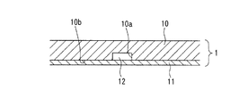
本発明の分析装置が備えるチップは、液体が充填される液体槽と微量の液体の送液や反応が行われる流路とを備えている。そして、この流路は、板面に溝を備える一対の平板状部材を貼り合わせることにより形成することが好ましい。すなわち、図1に示すように、板面に溝10aを備える平板状部材10の前記溝10aを備えた板面10bに、例えば樹脂製のカバーシート11を接着剤,粘着テープ等を介して貼り合わせると、液体の流路となるキャピラリ12を有するチップ1が形成される。
【0041】
この溝は、金型による成形やエンボス等の技術によって形成することができる。溝の形状,寸法については特に限定されるものではないが、現状の成形技術の観点からは、流路の幅と深さとの比が0.3〜10程度で、且つ、幅,深さはそれぞれ0.5μm以上が好ましく、必要とする試料,試薬の量の観点からは、幅,深さはそれぞれ500μm以下であることが好ましい。
【0042】
チップ(平板状部材)の材質として樹脂を採用する場合は、成形加工性が良好であることと、光学測定を実施する場合には透明であることが要求されるので、透明な熱可塑性樹脂を使用することが好ましい。チップの材質としてガラスを採用することも可能であるが、コストを考慮すると樹脂の方が好ましい。
具体的には、ポリスチレン、スチレン−アクリロニトリル共重合体等のスチレン系樹脂、ポリメチルメタクリレート、メチルメタクリレート−スチレン共重合体等のメタクリル樹脂、ポリカーボネート、ポリスルホン、ポリエーテルスルホン、ポリエーテルイミド、ポリアリレート、ポリメチルペンテン、1,3−シクロヘキサジエン系重合体などがあげられる。また、これらの共重合体やブレンド品を用いることも可能である。
【0043】
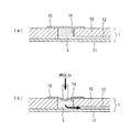
〔隔壁及び隔壁を用いた送液について〕
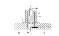
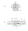
図2の(a)に示すように、液体槽14は平板状部材10に設けられた貫通孔により形成され、その開口部を覆うように弾性を有する隔壁15が取り付けられている。隔壁15は柔軟性を有していて変形可能であるので、図2の(b)に示すようにチップ1の外側から隔壁15に押圧力を作用させると、隔壁15が変形して液体槽14の内部に押し込まれる。
【0044】
そうすると、この隔壁15の変形によって液体槽14の容積が減少するので、液体は非圧縮性であることから、図2の(b)に矢印で示すように、液体槽14内の液体Lが前記容積変化分だけキャピラリ12に押し出される。これにより液体槽14内の液体Lを移動させることができる。
このように隔壁の変形を利用して送液を行えば、外部からチップに配管を繋ぐような複雑な機構,設備等を用いなくても、チップ内で所望の送液を行うことができる。また、チップに配管の接続口等の専用の設備を設ける必要がないため、簡便に低コストでチップを作製することができる。
【0045】
隔壁15は、柔軟性を有していて、小型の機構で変形可能なシート状のものであれば特に限定されるものではないが、PTFE(ポリ四フッ化エチレン)多孔質膜が特に好ましい。PTFE多孔質膜のように空気は透過し液体は透過しない(撥水性によりはじかれてしまう)性質の膜で隔壁15を形成すれば、隔壁15は通気性を有し且つ液体槽14が液体で満たされた際には耐水性を有する機能膜になる。よって、空の液体槽14内にキャピラリ12から液体Lを導入すると、液体槽14内の空気は液体Lが充填されるにしたがって押し出されて隔壁15を透過して抜けていくが、隔壁15の撥水性によって液体Lが透過して抜けていくことはないので、液体槽14内を液体Lで完全に満たされた状態にすることができる。
【0046】
PTFE以外にも、様々な素材の多孔膜が隔壁15として使用可能である。ただし、液体が膜を透過しないためには、疎水性の有機ポリマーや無機素材を用いることが好ましい。
疎水性の有機ポリマーは、臨界表面張力が20℃で約0.04N/m以下であることが好ましく、例としては、ポリテトラフルオロエチレン(PTFE)、シリコーン、ポリエチレン、ポリプロピレン、ポリスチレン、ポリ塩化ビニル、ポリカーボネート、ポリスルホン、ポリエーテルスルホン、ポリアリレート、ポリメチルペンテン、1,3−シクロヘキサジエン系重合体等があげられる。
【0047】
セルロースアセテート膜のようなものでも使用できる場合もあるが、界面活性剤が添加された試薬液の場合は、PTFE,シリコーン,ポリエチレン等の疎水性の強い膜の方が液体の透過を防ぐ耐水圧が大きいので好ましい。
耐水圧が大きいほど高い圧力で送液できるので、耐水圧は大きいほど好ましいが、本発明のチップに使用できる膜の耐水圧は、発明の実施の形態の項で後述するような流路構成では0.01MPa以上が好ましい。ただし、チップ内の流路や液体槽に迅速に液体を満たす必要がある場合には、耐水圧は0.1MPa以上であることがより好ましい。膜の平均孔径は0.1μmから約5μmのものが使用できるが、孔径が小さいほど耐水圧が高く透過空気量が僅かであることを考慮すると、0.1μm程度が最も好ましい。膜厚は25〜300μmのものが好ましい。
【0048】
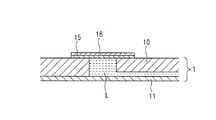
図3に示すように、隔壁15の外面に気体,液体のいずれも透過しない被膜16を被覆すると、耐水圧をさらに高めることができる。隔壁(PTFE多孔質膜)のみで被膜を有していない場合は、液体槽内の気体は隔壁を膜厚方向に透過するのに対し、図3のように被膜16を有していると、液体槽内の気体は隔壁15の膜内を外縁に向かって透過する。よって、隔壁15の膜厚が厚くなったことと同じであるので、耐水圧を高めることができる。このように隔壁に被膜を被覆する場合は、前述の0.1μm程度よりも大きい平均孔径を有する膜を隔壁として採用することができる。
【0049】
表面エネルギの高いPTFE多孔質膜等を隔壁として用いた場合は、前記被膜を隔壁に接着剤で接合することは、一般に困難である。その場合は、前記被膜の素材として低密度ポリエチレンのような熱可塑性樹脂を選択すれば、PTFE多孔質膜等へ前記被膜を熱圧着又は熱融着により接合することが可能である。
〔送液装置について〕
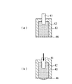
まず、本発明に係る送液機構において使用される送液装置の一例を、図4の概念図に示す。この送液装置は、圧力発生手段の一部をなすピストン41,非圧縮性媒質42,密閉容器43,及びダイアフラム部材44で構成されている。そして、非圧縮性媒質42は、密閉容器43とダイアフラム部材44とで囲まれた密閉空間に密封されている。
【0050】
図4の(b)に示すように、ピストン41により非圧縮性媒質42に圧力を印加する。このとき、ピストン41の非圧縮性媒質42内に存在する部分の体積が増加するが、この増加分は目的の送液量に等しい体積となるようにする。そうすると、密閉容器43中に充填された非圧縮性媒質42を介して前記圧力がダイアフラム部材44に伝達され、ダイアフラム部材44が密閉容器43の外側に向かって突出するように変形する。この突出した部分の体積は、密閉容器43の剛性が十分大きければ、前述した目的の送液量に等しい体積となる。
【0051】
このような送液装置5aを、図5の(a)に示すように、前述したようなチップ5bに装着する。その際には、送液装置5aのダイアフラム部材44の外側表面が、チップ5bの隔壁15の外面と密着するようにする。
図5の(b)に示すように、圧力発生手段を作動させてピストン41により非圧縮性媒質42に圧力を印加したときには、ダイアフラム部材44と隔壁15は密着しているので、前述したダイアフラム部材44の変形によって、隔壁15が液体槽14の内部に向かって突出するように変形する。そして、この隔壁15の変形によって液体槽14の容積が減少することとなるので、その容積の減少分だけ液体槽14内の液体Lが流路12を通じて外部へ送り出されることとなる。
【0052】
このとき、液体槽14の内部に突出した部分の体積は、前述のダイアフラム部材44が突出した部分の体積と等しいので、前述した目的の送液量に等しい体積の液体Lが送液されることとなる。すなわち、圧力発生手段による圧力が非圧縮性媒質42及びダイアフラム部材44を介して隔壁15に伝達され、隔壁15が変形することによって、液体槽14内の液体Lが外部へ送液されるのである。なお、非圧縮性媒質42に陰圧が負荷されるように圧力発生手段を作動すれば、液体槽14の容積が増大するので、前述の場合とは逆に、流路12を通じて液体槽14内に液体Lを引き込むことも可能である。これにより、流路12内又は流路12に連結する別の液体槽内の液体を移動させることができる。
【0053】
図4及び図5においては図示していないが、圧力発生手段は駆動源を備えており、その駆動源としては、例えばリニアステップモータ等のリニア型アクチュエータを用いることができる。
また、非圧縮性媒質42としては水,油等の液体があげられるが、実用上はシリコーンオイル等のように不揮発性である、室温において液体である、化学的に安定である等の性質を有するものが望ましい。液体の代わりに流動性が十分高いゲル状の物質を非圧縮性媒質として用いることもできる。本発明における所期の機能を発揮するためには、非圧縮性媒質中に気泡混入がないようにする必要がある。
【0054】
さらに、ダイアフラム部材44は、弾性を有し、非圧縮性媒質42を保持しうる薄板を用いて構成するが、その素材としては金属,樹脂などが好ましい。ダイアフラム部材44が突出した部分の体積と液体槽14の容積変化とが正確に等しくなるためには、ダイアフラム部材44及び隔壁15を介して対向する非圧縮性媒質42と液体槽14内の液体との対向面の形状を等しくし、ずれなく合わせることが好ましい。ただし、ダイアフラム部材44の外縁部が固定端として支持されている場合は、ダイアフラム部材44の外縁部の変形は微小であるから、非圧縮性媒質42と液体槽14内の液体との対向面の若干のずれは許容される。
【0055】
図5に示す送液機構においては、送液装置5aを繰り返し使用し、チップ5bを交換して用いることを想定しているが、これら両者を一体化して構成することも可能である。この場合は、図6に示すように、ダイアフラム部材を用いずに送液機構を構成することも可能である。
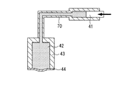
さらに、図7に示すように、密閉容器43と圧力発生手段の一部であるピストン41とを、非圧縮性媒質42が充填されたパイプ70(管状部材)で連結してもよい。このような構成とすれば、送液機構ひいては該送液機構を用いた分析装置のレイアウト設計上の自由度を高めることが可能である。
【0056】
図4〜7の送液機構は、圧力発生手段として往復式容積形ポンプ機構(ピストン・シリンダ機構又はプランジャ機構を有する容積形ポンプ機構)を採用しているが、圧力発生手段として別の機構を採用してもよい。例えば、リニア型アクチュエータと往復式容積形ポンプ機構の代わりに、回転モータとギヤポンプなどの回転式容積形ポンプ機構により圧力発生手段を構成することもできる。
【0057】
また、圧力発生手段、すなわち、体積変化を生じさせる手段として、上記のようなものの代わりに、物質の相変化に伴う体積変化を利用することが考えられる。例えば、パラフィンは室温から数十℃の温度変化で融解又は固化し、そのとき約15%の体積増減がある。パラフィン近傍に小型のヒータと温度センサを配置し、パラフィンの温度を制御すれば、体積変化をコントロールできる。
【0058】
相変化に伴う体積変化としては蒸発に伴う体積変化もあげられ、その体積変化の程度は固液相変化の場合よりもはるかに大きいが、気体は圧縮性が大きいので、定量送液が必要な場合には好ましくない。
図8の(a)に、相変化に伴う体積変化を利用した送液装置を示す。密閉容器43中に、非圧縮性媒質42と相変化に伴い体積変化を起こす物質81を収納する。相変化に伴う体積変化を起こす物質81は、液化した際に非圧縮性媒質42と混和しないように、前記体積変化に応じて膨張収縮自在な袋等(図示せず)に封入するべきであり、また、同袋内に加熱用のヒータ82を配置する。ヒータ82として温度によって電気抵抗が変化するサーミスタを採用し、該サーミスタに通電してその際の電圧降下を測定すれば、ヒータ機能と温度センサ機能とを兼ね備えた、小型で簡易な加熱装置を構成することが可能である。
【0059】
相変化に伴う体積変化は、非圧縮性媒質42を介して過不足なくダイアフラム部材44に伝達され、前記体積変化分だけダイアフラム部材44が突出し、本発明における送液装置として機能させることができる。なお、相変化に伴う体積変化を起こす物質81が非圧縮性媒質42と混合しない性質を有するならば、袋等に封入しなくてもよい。また、非圧縮性媒質42に代えて、相変化に伴い体積変化を起こす物質81で密閉容器43内を満たしても、同様の機能を実現可能である。
【0060】
物質の相変化に着目した圧力発生手段は、機械的要素を持たないため小型化が容易である。よって、図8の(b)に示すように、相変化に伴い体積変化を起こす物質81を、チップ内の液体槽14中に設置することも可能である。相変化を起こすための加熱手段としては、チップ近傍に設置したヒータ83で液体槽14とともに相変化を起こす物質81を加熱する方式が考えられる。また、レーザ集光加熱によって、相変化を起こす物質を加熱する方式も可能である。
【0061】
送液量を決定する体積変化は、非圧縮性媒質を介してダイアフラム部材の形状変化として表れ、さらに隔壁を介して液体槽中の液体に前記体積変化が伝達される。この体積変化の伝達が正確に行われるためには、以下のような要件が必要である。
第一に、ダイアフラム部材の形状変化が隔壁に正確に伝達されるためには、隔壁は極力柔軟なことが望まれる。また、液体槽内に液体を充填する際に液体槽内の気体を排除するために、隔壁にベント機能が必要となる。例えば、PTFE微多孔質膜は、この性質を備えている。
【0062】
第二に、ダイアフラム部材と隔壁との間に隙間がないことが好ましい。そのためには、まず送液装置とチップとを機械的に重ね合わせる。このとき、チップには製造上若干の反りがあるので、機械的に圧迫して両者の密着状態を高める。しかしながら、隔壁は柔軟性があり通常はたるみがあるため、微視的に見るとダイアフラム部材と隔壁との間には隙間があり、精密な定量送液においては無視できない場合がある。その場合には、隔壁の外面とダイアフラム部材の外面とを密着させることが必要となる。さらに、チップの交換を容易にするためには、密着状態と離脱状態とを容易に切り替えられることが要求される。
【0063】
密着状態と離脱状態との切り替えを実現する方法としては、図9に示すような真空を利用した方法があげられる。すなわち、ガスケット91等を用いてダイアフラム部材44と隔壁15との近傍部分を密封し、該近傍部分を図示しない真空ポンプ等を用いて陰圧にする。液体槽14内の液体Lは流路12を通じて大気圧に開放されていれば、隔壁15の内外面間の差圧で、隔壁15はダイアフラム部材44の表面に押しつけられ密着する。真空ポンプを停止してダイアフラム部材44と隔壁15との近傍部分を大気圧に戻せば、送液装置とチップとが容易に離脱する。
【0064】
送液装置を極めて安価に製造し、チップと一体化し使い捨てにする場合等においては、ダイアフラム部材と隔壁とを接着して、これらの間にすきまが生じないようにすることも可能である。
〔ゴム弾性を有する物質で非圧縮性媒質を構成した場合の送液について〕
本発明においては、前述のような一種のミニチュア的な油圧機構を送液装置の圧力発生手段として採用することが理想的である。しかしながら、ミニチュア的な油圧機構を実際に製作するには、精密な加工や組み立てが必要であり、また、作動油中から気泡を確実に排除することも必ずしも簡単ではない。そこで、ほぼ非圧縮性と見なしうる弾性体であるゴムを利用して、本発明における送液装置の構成要素である圧力発生手段,非圧縮性媒質,ダイアフラム部材を、より簡便に構成することができる。
【0065】
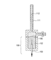
その例を図10に示す。一端が開口している筒状の容器101に、ゴム102が隙間なく充填されている。容器101の閉じた側の端部には微小な穴104が設けられていて、ゴム102に設けられた微小な穴105と連続している。そして、穴104から穴105にピン103が挿入されている。
理想化して考えると、ゴムは非圧縮性のため、挿入されたピン103の体積分だけゴム102の端面106が膨らむこととなる。この端面106とチップの隔壁とが密着するようにゴム102をチップに装着すれば、端面106の形状変化が隔壁を介して液体槽中の液体に伝達される。そして、ピン103の直径と挿入した長さから算出される体積の分だけ、前記液体が液体槽に連結された流路に送り出される。このような送液機構が正確に機能するためには、容器101が十分な剛性を持つこと、ゴム102に設けた穴105とピン103との間に隙間が生じぬように両者の径を選定することなどが必要である。
【0066】
なお、ゴム102に設ける穴105やピン103は、必ずしも断面円形状である必要はない。例えば、ゴム102に微小な穴105の代わりに亀裂を設け、ピン103に代わり金属製薄片を挿入することでも、同様の機能を実現できる。
また、上記のようなゴムを用いた送液機構が、変位縮小機構でもあることを説明する。まず、ゴムを用いた送液機構の場合について説明する。直径0.5mmのピンを用いた場合は、ピンの断面積は0.196mm2 であり、挿入長を5mmとすると体積変化すなわち送液量は1.0μLとなる。つまり、送液量1.0μLに対応する挿入長=アクチュエータ駆動量は5.0mmである。
【0067】
次に、仮にピン等で直接的に隔壁を押す場合について、アクチュエータ駆動量を概算してみる。隔壁の直径は3mmとし、ピンにより変形した隔壁の形状は円錐状であると仮定すれば、送液量1.0μLに対応するピンの挿入長は0.43mmとなる。したがって、アクチュエータ駆動量は、ゴムを用いた送液機構の場合はピン等で直接的に隔壁を押す場合に較べて約12倍である。単純に言うと、アクチュエータ駆動量の精度は一桁低くても問題ないので、駆動機構の低コスト化が可能になると思われる。
【0068】
【発明の実施の形態】
本発明に係る送液機構及び該送液機構を備える分析装置の実施の形態を、図面を参照しながら詳細に説明する。各図においては、同一又は相当する部分には同一の符号を付してある。なお、本実施形態は本発明の一例を示したものであって、本発明は本実施形態に限定されるものではない。
【0069】
〔分析装置について〕
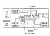
図11に、チップ,送液装置,光学的検出装置,温調装置など、検体の分析に必要な全ての装置・機器を備えた分析装置の全体構成を説明する概念図を示す。以下に、分析装置の機能を、動作の順を追って説明する。
チップローディング機構によって分析装置内にチップを導入した後、送液装置と温調装置とでチップを挟み、チップを所定の位置に固定する。温調装置を作動させてチップを加温しながら、チップが所定温度に到達するまでの時間を利用して、チップ内の空の流路及び液体槽に緩衝液を導入する準備操作を行う。送液装置を作動させて、後述するような希釈操作及び反応操作を行う。検体中の測定対象物質の濃度に応じた反応の程度を、光学的検出装置を用いて(例えば吸光度により)測定する。光学的検出装置としては、いわゆる熱レンズ現象に基づく光熱変換型検出機も利用可能であり、これは微細な流路中の吸光度を測定するのに好適である。測定過程は、統括CPUにより制御される。また、マンマシンインターフェースにより、測定の進捗状況や結果が測定者に適宜提示される。
【0070】
このような構成の分析装置により、チップを用いた分析をほぼ自動的に速やかに行うことが可能である。
〔チップについて〕
生化学測定用の分析装置に用いるチップの一例を、図12の模式図を参照しながら説明する。なお、このチップを用いた分析の過程については、後に詳述する。
【0071】
厚さ2mmの透明なアクリル製プレートの一方の板面に、幅100〜300μm、深さ50μm、長さ20〜250mm程度の数本の溝をエンボス加工により設けた。また、これらの溝の両端には直径4〜5mmの貫通孔を形成した。そして、前記プレートの溝を有する板面に、厚さ0.3mmの透明なアクリル製シートを紫外線硬化接着剤を用いて接着することにより、流路を構成した。
【0072】
さらに、前記プレートの他方の板面のうち前記貫通孔が形成された部分に、厚さ70μmのPTFE微多孔質膜(平均孔径0.1μm)を貼り付けて前記貫通孔の開口部分を覆うことにより、隔壁を構成した。市販のPTFE微多孔質膜では隔壁として必要な耐水圧が得られず、PTFE微多孔質膜に液体槽中の緩衝液が浸潤して、バルブ機能が喪失される場合があるが、PTFE微多孔質膜の外面(チップの外側を向いた面)をポリエチレン薄膜などの熱可塑性樹脂で被覆すれば、耐水圧を向上することができる。熱可塑性樹脂で被覆しても、液体槽内の空気排除の機能は、従来のものと遜色はなかった。なお、熱可塑性樹脂の被膜は、熱圧着又は熱融着によってPTFE微多孔質膜に接合することが好ましい。
【0073】
〔送液装置について〕
フルストロークで約0.8μLの送液量が得られる送液装置を、次のようにして作製した。両端が開口しているアクリル製円筒(外径13mm,内径5mm,高さ15mm)に、シリコーンゴム(ダウコーニング・ジャパン社製シルポット184)を高さ10mmまで満たし、重合して固化させた。シリコーンゴムの上に2液性エポキシ接着剤を充填し、その固化後に、直径1.0mmのドリルにてシリコーンゴム上端に到達するように穴あけ加工を行った。
【0074】
さらに、この穴に直径1.0mmの針を挿入し、シリコーンゴムの内部まで差し込むことにより、ゴムに後述するピンを抜き挿しするための亀裂状の穴を設けた。そして、直径0.9mmのピンを前記穴に差し込み、このピンに1ステップ25μmのリニア型アクチュエータを接続して、シリコーンゴムにピンを抜き差しできるようにした。
【0075】
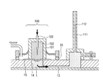
まず、前述のような送液装置において、ピンの挿入長とゴムの突出体積との関係を確認するため、図13に示す測定系を用意した。図13の測定系では、ピン103が差し込んである側を下方にして送液装置100を配置し、上方を向いたゴム端面106にガラス製キャピラリ111を取り付けている。気泡が残留しないように注意しながら、ガラス製キャピラリ111の下端側から水を注入し、キャピラリ全長の中程まで水を満たす。ピン103をゴム102に挿入した際の水面112の上下動を顕微鏡付き微動ステージ(図示せず)の昇降によって計測すれば、その計測結果とキャピラリ111の断面積とを用いて、ゴム端面106の突出による体積変化を算出できる。
【0076】
次に、図14に示すように、チップ上に前述の送液装置を配置した。その際には、前述のチップの隔壁15と送液装置のダイアフラム部材とが重なるように固定した。送液装置のアクリル製容器101の周囲にシリコーンゴム製のガスケット91を配置し、隔壁15の近傍部分を陰圧とするための図示しない小型真空ポンプ(到達真空度は−0.4MPa)を接続した。
【0077】
図14の測定系では、分岐や合流のない流路12の一端に、送液装置100が取り付けられ、他端にはガラス製キャピラリ111が取り付けられている。ガラス製キャピラリ111の上端から水を注入していき、隔壁15の通気性により空気を逃して、液体槽14内が満水になった時点で水の注入を停止する。ガラス製キャピラリ111の下端側から排水し、水面112がキャピラリ全長の中程になるように調整する。
【0078】
次に、前記小型真空ポンプを作動し、隔壁15と送液装置のゴム102の開放面とを密着させる。そして、ピン103をゴム102に挿入した際の水面112の上下動を前述の測定系と同様に測定することにより、挿入長と送液量との関係を得る。
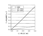
図15のグラフに、このようにして得たデータを示す。このグラフには、理論値として、ピン103の断面積とピン103の挿入長との積で与えられる体積を示している。グラフから分かるように、ゴム端面の突出体積は理論値に対して数%小さい値であった。これは、ゴムがポアソン比が0.49程度の近似的な非圧縮性物質であるため、若干の圧縮性を有しているためと考えられる(完全な非圧縮性物質であれば、ポアソン比は0.5となる)。送液量は、ゴム端面の突出体積とほぼ一致しており、隔壁を介して体積変化が伝達されていることを示している。
【0079】
ピンの挿入長に対する送液量の関係を変更したい場合には、ピンの断面積(直径)を変えればよい。その例を図16のグラフに示す。
〔相変化に伴う体積変化を利用した送液機構について〕
相変化時に体積変化を起こす物質を利用して圧力発生手段を構成することもできるので、以下に説明する。
【0080】
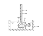
相変化時に体積変化を起こす物質としては、パラフィンを採用した。図17に示すように、ガラス製キャピラリ111の一端に数十μLの容積を有する容器151を接続した。そして、同容器151の内部に6mgのパラフィン152(和光純薬製、融点公称値46〜48℃)を封入し、キャピラリ111の下端側から容器151内に水を注入した。注入する水量は、液面112がキャピラリ111の中程に達する量とし、注水の際には水中に気泡が極力混入しないように注意を払った。
【0081】
パラフィンの密度を約1g/cm3 、相変化に伴う体積変化率を約15%とすれば、6mgのパラフィンの融解によって約1μLの体積変化が起こるはずである。この体積変化は、キャピラリ111内の液面112の移動として観察される。図17に示すように、容器151を囲むように配置された水槽153に約70℃の水を満たし、自然冷却により温度が次第に下がる時のキャピラリ111の液面112の変化を測定し、体積変化を求めた。
【0082】
実際には、パラフィンだけでなく水,容器151,キャピラリ111も温度により僅かではあるが体積変化を起こすので、測定値に誤差をもたらす。そこで、対照実験としてパラフィンを封入しない系についても液面変化を測定し、得られたデータをパラフィンを封入した系のデータから差し引くことにより、誤差を補正した。
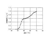
【0083】
このようにして得たパラフィンの固液相変化に伴う体積変化のデータを、図18のグラフに示す。70〜40℃の温度変化の過程で、約1μLの体積変化が生じることが確認できた。
なお、上記のような送液機構は、本発明に係る請求項24の送液機構の一例である。上記のような実験から、固液相変化に伴い体積変化を起こすパラフィン等の物質を、チップ内の流路に連続する液体槽内に封入した上、熱伝達等の手段により同物質を相変化させれば、液体を送液できることが示された。
【0084】
ただし、上記の例においては、パラフィンは水と混合しない性質を有しているので、送液される液体である水と隔離することなく液体槽内に水とともに封入したが、前記体積変化に応じて膨張収縮自在な袋等に入れるなどして送液される液体と隔離して液体槽内に封入するのであれば、送液される液体と混合する物質であっても、相変化に伴って体積が変化する物質として採用することができる。
【0085】
〔分析に必要な単位操作について〕
合流する流路を有するチップと送液装置とを組合わせることにより、分析に必要な単位操作である液体の希釈,混合等の操作を行うことができる。図19に、試験的に作製した希釈のみを行う分析装置を示し、その希釈の精度を評価した結果について述べる。
【0086】
図19の(a)は、チップとその上に固定された送液装置との構成を説明する断面図である。この送液装置は、前述のゴムを利用した送液装置3個が一体化されたものである。また、図19の(b)はチップの平面図である。このチップには4つの液体槽が形成されていて、そのうちP槽,Q槽,Q’槽は上記の3連の送液装置と同一ピッチで形成されている。
【0087】
一体化されたピン171を押し下げてゴム172に形成された穴に挿入すると、P槽,Q槽,Q’槽内の液体Lが各槽に連結する流路に送出されて、3つの流路の合流点で合流するようになっている。
また、P槽と、P槽から前記合流点までの流路と、前記合流点より下流側の流路(合流後流路)とには、測定対象である検体サンプルを模擬するキシレンシアノール色素水溶液(濃度は400μM)が充填してある。さらに、Q槽と、Q’槽と、Q槽から前記合流点までの流路と、Q’槽から前記合流点までの流路とには、緩衝液が充填してある。
【0088】
送液装置を作動させると、色素水溶液と緩衝液とが合流する。そして、両者が流路中で拡散・混合することで、希釈操作が行われる。ここでは、緩衝液用ピンの直径を0.7mm、検体サンプル(キシレンシアノール色素水溶液)用ピンの直径を0.3mmとしたが、希釈率を変更したい場合には、各液体槽に対応するピンの直径を変えればよい。
【0089】
合流後流路の終端近くに光熱変換型吸光度測定系(熱レンズ測定系)を配置すれば、該終端を通過する液体の濃度変化を捉えることができるので、希釈率を実測することが可能である。
図20に、希釈率を測定した結果を示す。このグラフには、送液開始後に希釈によって液体の吸光度が低下する様子が示されている。なお、別途測定した送液装置の特性を基にして、移流拡散現象を差分近似することによって数値計算した結果を、計算値として示している。
【0090】
グラフから分かるように実験値と計算値とは概ね一致しており、このことから本送液機構にて所期の希釈操作が実現できることが確認できた。
〔分析操作について〕
次に、チップを用いた分析の過程について詳述する。図12に、生化学測定用の分析装置のチップの構成を説明する模式図を示す。このチップには、9個の液体槽(P槽,Q槽,Q’槽,D槽,S槽,A槽,B槽,R槽,W槽)が備えられており、これらは流路により連通されている。
【0091】
P槽には血液から分離された血漿が充填され、A槽及びB槽には乾燥した反応試薬が槽の底部に付着されている。また、R槽には緩衝液が充填されている。また、各液体槽の開口部は、柔軟性,通気性,及び耐水性を有する隔壁(ポアサイズ約0.1μm、耐水圧0.39MPaのPTFE多孔質膜)で覆われている。P槽,Q槽,及びQ’槽には、図19に示す3連の送液装置が装着されている。また、D槽及びR槽には、図14に示すような送液装置100がそれぞれ装着されている。さらに、W槽には図21に示すバルブ201が装着され、初期状態ではバルブ201は閉状態とされている。バルブ201は、ガスケット202によりW槽の隔壁15の周囲を密閉するように設置されている。バルブ201が開状態であれば、W槽内の空気が隔壁を通過してバルブ201の外に流出でき、バルブ201が閉状態であれば、W槽内の空気が隔壁を通過してバルブ201の外に流出することが阻止される。したがって、バルブ201を開状態又は閉状態とすることにより、W槽内の空気を液体で置換するか否かを選択することができる。
【0092】
まず、R槽に取り付けられた送液装置を作動させ、緩衝液をチップ内の流路全体に充填する。すなわち、R槽に配された送液装置によってR槽内に充填されている緩衝液が押し出されるが、W槽のバルブ201が閉状態とされているため、緩衝液は流路sab,sa,sを通ってS槽,A槽,B槽に流入する。
S槽が満杯になると緩衝液はQ槽及びQ’槽へと流入するが、P槽は既に検体で満たされているため、P槽には流入しない。また、A槽及びB槽が満杯になると、緩衝液はD槽へ流入する。最終的にはQ槽,Q’槽,D槽,S槽,A槽,B槽への緩衝液が充填が完了する。W槽は、バルブ201が閉状態であるため、緩衝液は通過するのみで、W槽内はほぼ空気で満たされた状態である。
【0093】
この過程において、A槽,B槽に収納されていた乾燥A試薬と乾燥B試薬は緩衝液に溶解するので、A槽,B槽には各々の試薬溶液が準備される。試薬溶液の濃度は、液体槽の容積と乾燥試薬の量とで所望の値に設定することができる。このような操作により、試薬の溶解と送液のための緩衝液の各液体槽への充填とが完了した。
【0094】
次に、検体の希釈操作を行う。W槽のバルブ201を開状態とし、P槽,Q槽,及びQ’槽に装着された送液装置によって検体と緩衝液とを同時に押し出すと、両液が拡散、混合し、その混合液がS槽に流入する。すなわち、S槽内の緩衝液が希釈された検体で置換される。S槽内に当初存在した緩衝液は、流路s,流路sa,流路sabを通って廃液槽であるW槽に流入する。なお、検体の希釈の比率は、P槽,Q槽,及びQ’槽に装着された送液装置の設定流量によって決定される。
【0095】
この段階で、S槽に希釈検体が充填され、A槽,B槽には各々の試薬溶液が充填された状態となり、反応の準備が整った。
最後に、D槽に装着された送液機構によってD槽内に充填されている緩衝液を押し出すと、3分岐流路を介してS槽,A槽,B槽に緩衝液が流入し、これらに連結するそれぞれの流路へ、各液体槽の内容液が送出される。すなわち、流路sには希釈検体が、流路aにはA試薬溶液が、流路bにはB試薬溶液が送出される。このとき、緩衝液は液押し用液体として作用する。
【0096】
それぞれの流路には、3分岐流路の分岐点における各流路の圧力損失が等しくなるように、流量が配分される。チップの設計においては、希釈検体及びA,B各試薬溶液の流量が所望の値となるように、各液体の粘性の違いを勘案した上で、各流路の圧力損失係数を決定する。圧力損失係数は、流路断面の形状と流路長の2つの因子で決定される。なお、P槽,Q槽,及びQ’槽に装着された送液装置は停止しているので、これらの液体槽への液体の流入はない。
【0097】
希釈検体とA試薬溶液は流路saに流入し混合され、流路saで検体とA試薬との反応が起こる。この混合液は反応しながら流路bとの合流点に向かって流れ、流路saを流れる時間を反応時間とすれば、流速と流路saの長さとによって反応時間をコントロールすることができる。
検体とA試薬との反応が予定の時間進行した後、流路bとの混合点に到達させる。これにより、さらにB試薬と混合して反応が起きることによって、最終的な濃度測定が行える混合溶液が流路sabに流れることとなる。混合後、試薬反応系に適合するような適当な反応時間を経て、色素濃度として標識化される。流速を考慮して十分な反応時間をとれるように流路sabの長さを設定すれば、反応後、直ちに、図11で説明したような光学測定装置を使用して樹脂の基板を通して流路内の溶液の濃度測定が可能となる。
【0098】
濃度測定が行われた混合液は、W槽(廃液槽)へ到達し廃液として貯留される。濃度測定の後のチップはそのまま使い捨てにすることができるので、分析作業者に検体由来の感染等が発生することがない分析システムを構築することが可能である。
また、血液などの試料検体の希釈や抽出プロセスなども同様に考えることができ、上記のような方式を用いれば、考えられる試薬反応プロセスについてはほとんどが実現可能となる。
【0099】
【発明の効果】
以上のように、本発明の分析装置は、POC分析等をはじめとする種々の分析を簡便且つ正確に行うことができる。また、本発明の送液機構は、前記分析装置における液体の送液に好適で、小型且つ簡易な構成であり、低コストである。
【図面の簡単な説明】
【図1】本発明の分析装置のチップの構成を説明する断面図である。
【図2】本発明における送液原理を説明する模式図である。
【図3】隔壁の耐水圧を向上させる手段を説明する模式図である。
【図4】送液装置の原理を説明する模式図である。
【図5】送液装置とチップとを組み合わせて送液を行う原理を説明する模式図である。
【図6】本発明における別の送液機構を説明する模式図である。
【図7】密閉容器と圧力発生手段とをパイプで接続した構成を有する送液装置の模式図である。
【図8】固液相変化に伴い体積変化を起こす物質を圧力発生手段に利用した送液機構を説明する模式図である。
【図9】ダイアフラム部材と隔壁とを確実に密着する手段を説明する模式図である。
【図10】非圧縮性媒質をゴムで構成した送液装置の模式図である。
【図11】本発明の一実施形態の分析装置の全体構成を示す模式図である。
【図12】検体の希釈操作及び反応操作を行うためのチップの流路構成を説明する模式図である。
【図13】送液装置による送液量の測定方法を説明する模式図である。
【図14】送液装置及びチップによる送液量の測定方法を説明する模式図である。
【図15】図14の送液装置及びチップにおいて、ピンの挿入長と送液量との相関を測定した結果を示すグラフである。
【図16】ピンの直径を変えてピンの挿入長と送液量との相関を測定した結果を示すグラフである。
【図17】固液相変化に伴い体積変化を起こす物質を圧力発生手段に利用した送液機構において、送液量の測定方法を説明する模式図である。
【図18】図17の送液機構について送液の特性を測定した結果を示すグラフである。
【図19】送液装置及びチップを用いて行う希釈操作を説明する模式図である。
【図20】図19の送液装置及びチップを用いて行った希釈操作の特性を測定した結果を示すグラフである。
【図21】検体の希釈操作及び反応操作を行うにあたり、前準備操作において用いるバルブの構造を示す模式図である。
【符号の説明】
1,5b チップ
10 平板状部材
10a 溝
10b 板面
11 カバーシート
12 キャピラリ(流路)
14 液体槽
15 隔膜
16 被膜
41 ピストン
42 非圧縮性媒質
43 密閉容器
44 ダイアフラム部材
70 パイプ
81 相変化に伴い体積変化を起こす物質
82,83 ヒータ
101 容器
102,172 ゴム
103,171 ピン
104 穴
105 穴
152 パラフィン
L 液体[0001]
BACKGROUND OF THE INVENTION
The present invention relates to an analyzer that can easily analyze and detect a trace amount of sample. The present invention also relates to a liquid feeding mechanism suitable for liquid feeding in the analyzer.
[0002]
[Prior art]
Analyzes for bedside diagnosis (POC (point of care) analysis) that performs measurements necessary for medical diagnosis in the vicinity of patients, and analyzes of hazardous substances in rivers and wastes at rivers and waste disposal sites (POU (point of use) analysis) and analysis / measurement at or near the site where analysis / measurement is required, such as contamination inspection at food cooking, harvesting and import sites The importance of (hereinafter collectively referred to as “POC analysis, etc.”) is attracting attention. In recent years, the development of detection methods and apparatuses applied to such POC analysis and the like is being emphasized. Such POC analysis and the like are required to be performed simply in a short time and at a low cost.
[0003]
Conventionally, for microanalysis, a GC-MS apparatus or an LC-MS apparatus, in which a sample is separated by capillary gas chromatography (CGC), capillary liquid chromatography (CLC), etc. and then quantified by a mass spectrometer, has been widely used. It was. However, these analyzers are suitable for use in on-site measurements such as patient bedsides, contaminated rivers, waste disposal sites, etc., due to the large mass spectrometer and complicated operation. Not. Furthermore, it is desirable that an analyzer for medical diagnosis using blood or the like as a sample should be disposable at the part touched by the sample.
[0004]
Therefore, in order to solve these problems, studies have been made to reduce the size of a conventionally used analyzer and apply μTAS (micro total analysis system) technology for reacting a very small amount of liquid reagent to POC analysis and the like. did it. In μTAS, a groove is formed on the surface of a glass or silicon chip of about 10 cm to several centimeters or less in order to reduce the amount of a specimen, not limited to blood, and a reagent solution or specimen is allowed to flow through the groove. A small amount of sample is analyzed by separation and reaction (JP-A-2-245655, JP-A-3-226666, JP-A-8-233778, Analytical Chem. 69, 2626-2630 (1997). ) Aclara Biosciences). This technology has the advantage that the amount of specimen, the amount of reagent necessary for detection, the amount of waste such as consumables used for detection, and the amount of waste liquid are all reduced, and the time required for detection can be reduced to a short time. is there.
[0005]
The applicant of the present application is also disclosed in Japanese Patent Application No. 10-181586 (“mixing analysis apparatus and mixing analysis method”), Japanese Patent Application Laid-Open No. 2000-2675 (“capillary photothermal conversion analysis device”), and Japanese Patent Application Laid-Open No. 2000-2777. (“Analyzer”), International Publication No. WO99 / 64846, Japanese Patent Application No. 11-227624 (“Analytical Cartridge and Liquid Feed Control Device”) and other inventions relating to μTAS have been filed.
[0006]
These publications or application specifications also describe using a resin microchip as a chip and using a thermal lens detection method as a trace component detection method.
The thermal lens detection method is a photothermal conversion detection method in which a sample in a liquid is excited with excitation light to form a so-called thermal lens, and the change in the thermal lens is measured with the detection light. (Japanese Patent Laid-Open No. 60-174933, A.C. Boccara et.al., Appl. Phys. Lett. 36, 130, 1980, J. Liquid Chromatography 12, 2575-2585 (1989), 10-142177, JP-A-4-369467, Bunkeki No. 4,280-284, 1997, M. Harada, et.al., Anal.Chem.Vol.65, 2938-2940, 1993, Kawanishi , Et al. Abstracts of the 44th Annual Meeting of the Analytical Society of Japan, p119, 1995, etc.).
[0007]
As a method for measuring the components in the capillary, a fluorescence method or an absorbance method can be used in addition to the thermal lens detection method, but high sensitivity can be realized without an operation such as introduction of a fluorescent labeling substance. Thermal lens detection is suitable.
On the other hand, capillary electrophoresis itself or a method of feeding a liquid by applying a voltage using electroosmotic flow has also been proposed (International Publication WO96 / 04547, S. C. Jakobson, et.al.). Chem. Vol. 66, 4127-4132, 1994, J.
[0008]
However, since both electrophoresis and electroosmotic flow apply a voltage to the liquid in the chip via the electrode, the reagent and sample composition change due to electrolysis of the measurement reagent and measurement sample on the electrode surface. There is. In addition, a phenomenon may occur in which the electrolytic product of the reagent or sample adheres to the inner surface of the capillary, changes the zeta potential on the capillary surface, and changes the liquid feeding speed.
[0009]
In addition, a solid reagent freeze-dried is placed in the cartridge, the blood sample is diluted with a lysis dilution solution enclosed in the cartridge, and the solid reagent is further dissolved in the diluted sample solution, and an analytical reaction is performed for quantification. Methods have been disclosed (Japanese Patent Publication No. 10-501340, Japanese Patent Publication No. 9-504732, etc.).
In this method, since liquid feeding is performed by centrifugal force, the liquid feeding direction is always the direction in which the centrifugal force works, that is, the direction from the center of the circle of the circular cartridge to the outside. The solid reagent is placed in a small chamber along the circumference located at the end of the flow path in the cartridge. The diluted specimen flows into each small chamber, dissolves the solid reagent, reacts, and changes to absorbance. Come to come.
[0010]
However, because of the structure of the cartridge, since the solid reagent is placed at the final point of the flow path, only a one-step detection reaction with one reagent can be performed. Depending on the detection item, a clinical laboratory in a test center or hospital Therefore, it is necessary to adopt a reaction and reagent composition different from the detection reaction based on the recommended method established by academic societies or government offices. Therefore, the correlation with conventional inspection data may be low. Further, depending on the inspection item, it may be difficult to analyze in such a circular cartridge reaction mode.
[0011]
On the other hand, a liquid feeding method using bubbles in a sealed capsule has been reported. This includes liquid feeding due to thermal expansion of bubbles and liquid feeding due to generation of electrolytic gas. The former is performed by a sealed chamber, a heating material, and a filling liquid. The expansion of the heated bubbles generates a high pressure and enables fast liquid feeding. For example, in the method of Naruse Yoshihiro et al., When a light-absorbing heat generating material is sealed in a chamber filled with liquid and the laser light is guided into the chamber with glass fiber, bubbles in the chamber expand due to heat generation of the light-absorbing heat generating material. In this case, the liquid is fed (USP 5210817 specification).
[0012]
On the other hand, the latter is performed by a sealed chamber, an electrolytic solution filled therein, and a pair of electrodes inserted in the chamber. Pressure is generated by the generation of electrolytic gas by applying a voltage to the electrodes, and liquid feeding is performed. For example, DAHopkins, Jr (USP 5671905 specification) and CRNeagu et al. (CRNeagu, JGEGardeniers, M. Elwenspoek, JJKelly, Journal of Micro Electro Mechanical Systems, 5, 1, 2-9, (1996)) There is something to report.
[0013]
However, since bubbles have compressibility, when a liquid is sent into a narrow capillary channel, it takes a long time to stabilize after the liquid flow starts. In some cases, the liquid may vibrate in the flow direction, which may cause a problem that the liquid feeding is not stabilized at all.
Furthermore, a method of sending the liquid by pushing the filling liquid from the outside without using bubbles has been proposed, for example, liquid feeding by a piezoelectric element. A piezoelectric element can generate a large force with a relatively small amount of energy.
[0014]
However, when the piezoelectric element is composed of a single crystal, the liquid can be pushed and moved only by a very small distance. In order to increase the stroke, the piezoelectric element is usually constituted by a plurality of crystals. However, if this is done, a large number of parts are required, resulting in an increase in cost.
In addition, since the piezoelectric element is driven with a small current but requires a high voltage, it is not necessarily adapted to the present semiconductor circuit. Furthermore, it is necessary to form piezoelectric elements by laminating materials having different expansion coefficients, and accurate clearance is required for lamination, so it is difficult to reduce the size. Furthermore, because it is a reciprocating motion due to vibration, in order to convert it into a unidirectional force suitable for liquid feeding, it is necessary to use multiple valves with check valve functions or to add phase differences to multiple pumps. There is a problem that the entire system becomes very complicated because control is required. Although it is possible to perform liquid feeding by installing a module having a rectifying effect such as a diffuser in the flow path, the rectifying effect cannot be expected unless the flow rate is high due to its structural characteristics. Although it is possible to increase the speed by narrowing the flow path width at low flow rates, this method increases the pressure loss in the flow path, and it is necessary to improve the chip manufacturing accuracy and flow control accuracy. It becomes difficult to build a practical system for reasons such as high costs.
[0015]
Furthermore, liquid feeding based on the principle of electrostatic charge repulsion and counter charge is reported. For example, in the method of R. Zengerle et al., The liquid in the chamber is pushed out by electrostatic repulsion between the thin membrane electrode and the fixed chip electrode (R. Zengerle, A. Richter, H. Sandmaier, Micro Electro Mechanical Systems '' 92, 4, 19, (1992)).
[0016]
However, since the gap distance is sensitive to liquid feeding, the actual liquid feeding is limited to a few μm. This narrow gap is sensitive to contamination by dust and the like, and easily attracts dust in a high electric field. Such contamination prevents proper liquid feeding. Moreover, since a large current is not required but a high voltage is required, it is not necessarily adapted to today's semiconductor circuits. Furthermore, a large capacity charged plate is required to obtain a large liquid feeding force. Furthermore, since the reciprocating motion is caused by vibration, a plurality of pilot valves that are electrically controlled or have a check valve function are required to convert the force into a unidirectional force suitable for liquid feeding. There was a problem that the whole became very complicated.
[0017]
[Patent Document 1]
US Pat. No. 5,210,817
[Patent Document 2]
US Pat. No. 5,671,905
[Non-Patent Document 1]
C.R.Neagu, J.G.E.Gardeniers, M.Elwenspoek, J.J.Kelly, "Journal of Micro Electro Mechanical Systems", 1996, Vol. 5, No. 1, p.2-9
[Non-Patent Document 2]
R. Zengerle, A. Richter, H. Sandmaier, "Micro Electro Mechanical Systems '92", 1992, Volume 4, p.19
[0018]
[Problems to be solved by the invention]
As described above, there are many proposals as a liquid delivery technology to be provided to a device that performs POC analysis and the like. However, there are still solutions that meet all of the requirements of our target devices such as multi-item, small size, simple, short time, and low cost. Not proposed. Specifically, the device is small and can be manufactured easily, the operation is not complicated and can be measured easily, the analysis chip can be disposable from the viewpoint of preventing contamination, and the test results are the same as the conventional test method Those that have correlation, those that can measure concentration by photothermal conversion detection method (thermal lens method), etc., those that do not have a complicated connection mechanism between the external liquid delivery device and the analysis chip, and concentrations to ensure accuracy There is a demand for a liquid feeding mechanism that can satisfy many requirements such as one that can perform a standard solution reaction.
[0019]
Therefore, the present invention solves the problems of the conventional techniques as described above, and its mechanism is simple, small and low cost, and is suitable for an analysis apparatus for performing various analyzes such as POC analysis. It is an object to provide a liquid feeding mechanism. It is another object of the present invention to provide an analyzer that includes the liquid feeding mechanism and can easily perform various analyzes including POC analysis in a short time.
[0020]
[Means for Solving the Problems]
In order to solve the above problems, the present invention has the following configuration. That is, in the liquid feeding mechanism according to the first aspect of the present invention, the liquid filled in the liquid tank is connected to the liquid tank by changing the volume of the liquid tank surrounded by the wall body. Or a liquid feeding mechanism that sends the liquid stored in the flow path or another liquid tank connected to the flow path to the liquid tank, wherein at least a part of the wall body is A diaphragm member that is configured by a partition wall having elasticity that can be deformed so as to protrude toward the inside or the outside of the liquid tank, and that is in contact with the outer surface of the partition wall;Composed of a material having rubber elasticity andAn incompressible medium that is in contact with a surface of the diaphragm member that is not in contact with the partition; a container that stores the incompressible medium; and a pressure generating unit that applies pressure to the incompressible medium. The incompressible medium is sealed in a sealed space surrounded by the diaphragm member and the container,The pressure generating means includes the container provided with holes or cracks, the incompressible medium provided with holes or cracks continuous with the holes or cracks of the container, and the holes of the container and the incompressible medium. Or a pin or flake inserted in a crack and reciprocating,The pressure is applied to the partition via the incompressible medium and the diaphragm member, so that the partition is deformed.
[0021]
Moreover, the liquid feeding mechanism of claim 2 according to the present invention comprises:By changing the volume of the liquid tank formed surrounded by the wall body, the liquid filled in the liquid tank is sent to the flow path connected to the liquid tank, or the flow path or the flow path A liquid feeding mechanism for sending a liquid stored in another connected liquid tank to the liquid tank, wherein at least a part of the wall body can be deformed so as to protrude toward the inside or the outside of the liquid tank. A diaphragm member that is in contact with the outer surface of the partition wall, an incompressible medium that is in contact with a surface of the diaphragm member that is not in contact with the partition wall, and the incompressible medium. And a pressure generating means for generating a pressure using a volume change accompanying a solid-liquid phase change of the substance and loading the pressure on the incompressible medium, wherein the incompressible medium is the Diaphragm member The partition is sealed in a sealed space surrounded by the container, and the pressure is applied to the partition via the incompressible medium and the diaphragm member, so that the partition is deformed. And
Furthermore, the liquid feeding mechanism of claim 3 according to the present invention comprises:3. The liquid feeding mechanism according to claim 2, further comprising at least one of a heating device and a cooling device that controls a temperature of the substance to cause a volume change accompanying a solid-liquid phase change in the substance.
[0022]
Furthermore, the liquid feeding mechanism of claim 4 according to the present invention comprises:The liquid feeding mechanism according to claim 2 or 3, wherein the container and the pressure generating means are connected by a tubular member filled with an incompressible medium.
Furthermore, the liquid feeding mechanism of claim 5 according to the present invention comprises:The liquid feeding mechanism according to any one of claims 1 to 4, wherein the partition wall and the diaphragm member are brought into close contact with each other by reducing the vicinity of the contact portion between the partition wall and the diaphragm member to less than atmospheric pressure. A means for releasing the adhesion between the partition wall and the diaphragm member by setting the vicinity of the contact portion to atmospheric pressure is provided.
[0023]
Furthermore, the liquid feeding mechanism of claim 6 according to the present invention comprises:By changing the volume of the liquid tank formed surrounded by the wall body, the liquid filled in the liquid tank is sent to the flow path connected to the liquid tank, or the flow path or the flow path A liquid feeding mechanism for sending a liquid stored in another connected liquid tank to the liquid tank, wherein at least a part of the wall body can be deformed so as to protrude toward the inside or the outside of the liquid tank. A diaphragm member that is in contact with the outer surface of the partition wall, an incompressible medium that is in contact with a surface of the diaphragm member that is not in contact with the partition wall, and the incompressible medium. And a pressure generating means for applying pressure to the incompressible medium, wherein the incompressible medium is sealed in a sealed space surrounded by the diaphragm member and the container, pressure The partition is deformed by being applied to the partition via the incompressible medium and the diaphragm member, and further, the vicinity of the contact portion between the partition and the diaphragm member is reduced to less than atmospheric pressure. Thus, the partition wall and the diaphragm member are brought into close contact with each other, and a means for releasing the close contact between the partition wall and the diaphragm member by setting the vicinity of the contact portion to atmospheric pressure is provided.
Furthermore, the liquid feeding mechanism of claim 7 according to the present invention comprises:The liquid feeding mechanism according to claim 6, wherein the container and the pressure generating means are connected by a tubular member filled with an incompressible medium.
[0024]
Furthermore, the liquid feeding mechanism of claim 8 according to the present invention comprises:8. The liquid feeding mechanism according to claim 6, wherein the pressure generating means generates the pressure using a reciprocating positive displacement pump mechanism.
[0025]
Furthermore, the liquid feeding mechanism according to claim 9 of the present invention isThe liquid feeding mechanism according to claim 6 or 7, wherein the pressure generating means generates the pressure using a rotary positive displacement pump mechanism.
[0026]
Furthermore, the liquid feeding mechanism of
Furthermore, the liquid feeding mechanism of
[0027]
Furthermore, the liquid feeding mechanism of
Furthermore, the liquid feeding mechanism of claim 13 according to the present invention comprises:The liquid feeding mechanism according to claim 11 or 12, wherein the container and the pressure generating means are connected by a tubular member filled with an incompressible medium.
[0028]
Furthermore, the liquid feeding mechanism of
Furthermore, the liquid feeding mechanism of
[0029]
Furthermore, the liquid feeding mechanism according to claim 16 of the present invention includes:16. The liquid feeding mechanism according to
Furthermore, the liquid feeding mechanism of claim 17 according to the present invention comprises:17. The liquid feeding mechanism according to claim 15 or 16, wherein the pressure generating means generates the pressure using a reciprocating positive displacement pump mechanism.
[0030]
Furthermore, the liquid feeding mechanism of claim 18 according to the present invention comprises:17. The liquid feeding mechanism according to claim 15 or 16, wherein the pressure generating means generates the pressure using a rotary positive displacement pump mechanism.
Furthermore, the liquid feeding mechanism of claim 19 according to the present invention comprises:The liquid feeding mechanism according to any one of claims 1 to 18, wherein the partition wall is made of a material that allows gas to permeate but does not allow liquid to permeate.
Furthermore, the liquid feeding mechanism of claim 20 according to the present invention comprises:The liquid feeding mechanism according to claim 19, wherein the material is a porous film having hydrophobicity.
[0031]
Furthermore, the liquid feeding mechanism of claim 21 according to the present invention is the liquid feeding mechanism of claim 20,The porous film is formed of an organic polymer.
Furthermore, the liquid feeding mechanism of claim 22 according to the present invention comprises:The liquid feeding mechanism according to any one of claims 19 to 21, wherein a coating that does not transmit gas and liquid is coated on an outer surface of the partition wall.
[0032]
Furthermore, the liquid feeding mechanism according to claim 23 of the present invention is the liquid feeding mechanism according to claim 22,The film is bonded to the partition wall by thermocompression bonding or heat fusion.
Furthermore, the liquid feeding mechanism of claim 24 according to the present invention comprises:A liquid filled in a liquid tank surrounded by a wall body is sent to a flow path connected to the liquid tank, or stored in the flow path or another liquid tank connected to the flow path. A liquid feeding mechanism for sending the liquid to the liquid tank, wherein a substance whose volume changes with a phase change is enclosed in the liquid tank so as not to be mixed with the liquid to be fed. And
[0033]
Furthermore, the liquid feeding mechanism of claim 25 according to the present invention comprises:25. The liquid feeding mechanism according to claim 24, wherein the substance is isolated from the liquid to be fed and sealed in the liquid tank.
Furthermore, the liquid feeding mechanism of claim 26 according to the present invention is characterized in that, in the liquid feeding mechanism of claim 24, the substance does not mix with the liquid to be fed.
Furthermore, the liquid feeding mechanism of Claim 27 which concerns on this invention is a liquid feeding mechanism as described in any one of Claims 24-26. The volume change accompanying a phase change to the said substance by controlling the temperature of the said substance. It is characterized by comprising at least one of a heating device and a cooling device for generating the above.
With the liquid feeding mechanism having such a configuration, accurate liquid feeding can be performed even with a very small amount of liquid. Further, the mechanism is simple, small, and low in cost, and can be suitably applied to an analyzer that performs various analyzes such as POC analysis.
[0034]
Further, if the partition wall is made of a material that allows gas to permeate but does not allow liquid to permeate, it acts as an air vent when filling the liquid into the liquid tank or the flow path, and deforms when the liquid is fed. Since the liquid can be pushed or pulled, it is possible to easily configure the liquid feeding mechanism without using a special valve or mechanism.
In the present invention, the above-mentioned “outer surface of the partition wall” means a surface facing the outside of the liquid tank among the two surfaces of the partition wall.
[0035]
Furthermore, according to the present inventionClaim 28The analyzer is an analyzer that analyzes a predetermined component in the sample or the liquid mixture by flowing a liquid sample or a liquid mixture of the liquid sample and the liquid reagent into the flow path. A chip having a liquid tank filled with the sample or the mixed liquid, and the flow path connected to the liquid tank, and27One ofOne paragraphAn analysis apparatus comprising the liquid feeding mechanism described in 1.
[0036]
Furthermore, according to the present inventionClaim 29The analyzer ofClaim 28In the analysis apparatus according to the above, the chip is configured by bonding a pair of flat plate members, and at least one of the pair of flat plate members includes a groove on the plate surface, and the plate surface including the groove is provided. The flow path is formed by laminating inward.
[0037]
Furthermore, according to the present inventionClaim 30The analyzer ofClaim 28 or Claim 29In the analyzer according to the above, the chip includes a liquid tank in which a dry reagent is stored, and the liquid is loaded into the liquid tank and the reagent is dissolved in the liquid by dissolving the reagent. It is possible to prepare a reagent in the shape of the chip.
[0038]
With the analyzer having such a configuration, various types of analysis including POC analysis can be performed easily and accurately in a short time. Further, since it is not necessary to provide a special device or mechanism for preparing a reagent solution necessary for analysis outside the chip, the configuration of the analyzer can be simplified.
Furthermore, according to the present inventionClaim 31The analyzer ofAny one of Claims 28-30.In the analyzer described in the above, the analyzer includes a mechanism for simultaneously moving the liquid in the plurality of liquid tanks or the plurality of flow paths with the liquid pushing liquid,Any one of Claims 1-27The liquid pushing flow path through which the liquid pushing liquid fed by the liquid feeding mechanism described in 1 is connected to the plurality of liquid tanks or the plurality of flow paths, respectively.
[0039]
With such a configuration, operations such as liquid mixing and dilution necessary for analysis can be freely performed in the chip.
Hereinafter, a liquid feeding mechanism and an analyzer according to the present invention will be described in detail with reference to the drawings.
The liquid feeding mechanism of the present invention is mainly composed of two parts. That is, a liquid tank including a partition and a part having a flow path (a part corresponding to a chip, and will be referred to as a chip in the following description), and a part for changing the volume of the liquid tank by deforming the partition (hereinafter referred to as a chip) In the description, it is referred to as a liquid feeding device). In order to realize quantitative liquid feeding required for POC analysis or the like, it is necessary for the liquid feeding device to change the shape of the partition wall so that a volume change equal to the target liquid feeding amount is generated in the liquid tank. There is a need to accurately deliver a target amount according to the volume change of the liquid tank.
[0040]
[About chip]
The chip provided in the analyzer of the present invention includes a liquid tank filled with a liquid and a flow path in which a small amount of liquid is fed and a reaction is performed. And it is preferable to form this flow path by bonding a pair of flat plate-like members having grooves on the plate surface. That is, as shown in FIG. 1, a
[0041]
This groove can be formed by a technique such as molding using a mold or embossing. The shape and dimensions of the groove are not particularly limited, but from the viewpoint of the current molding technique, the ratio of the width and depth of the flow path is about 0.3 to 10, and the width and depth are Each is preferably 0.5 μm or more, and from the viewpoint of the amount of sample and reagent required, the width and depth are each preferably 500 μm or less.
[0042]
When resin is used as the material of the chip (flat plate member), it is required to have good molding processability and to be transparent when performing optical measurement. It is preferable to use it. Glass can be used as the material of the chip, but a resin is preferable in consideration of cost.
Specifically, styrene resins such as polystyrene and styrene-acrylonitrile copolymer, methacrylic resins such as polymethyl methacrylate and methyl methacrylate-styrene copolymer, polycarbonate, polysulfone, polyethersulfone, polyetherimide, polyarylate, Examples thereof include polymethylpentene and 1,3-cyclohexadiene polymers. These copolymers and blends can also be used.
[0043]
[Bulk and liquid feeding using bulkhead]
As shown to (a) of FIG. 2, the
[0044]
Then, since the volume of the
Thus, if liquid feeding is performed using the deformation of the partition wall, a desired liquid feeding can be performed in the chip without using a complicated mechanism, equipment, or the like that connects the pipe to the chip from the outside. In addition, since it is not necessary to provide a dedicated facility such as a pipe connection port on the chip, the chip can be easily produced at low cost.
[0045]
The
[0046]
Besides PTFE, porous films made of various materials can be used as the
The hydrophobic organic polymer preferably has a critical surface tension of about 0.04 N / m or less at 20 ° C., for example, polytetrafluoroethylene (PTFE), silicone, polyethylene, polypropylene, polystyrene, polyvinyl chloride Polycarbonate, polysulfone, polyethersulfone, polyarylate, polymethylpentene, 1,3-cyclohexadiene polymer, and the like.
[0047]
Cellulose acetate membranes may be used in some cases, but in the case of a reagent solution with a surfactant added, a highly hydrophobic membrane such as PTFE, silicone, polyethylene, etc. is more resistant to water permeation. Is preferable because it is large.
Since the higher the water pressure, the higher the water pressure, the higher the water pressure, the better. However, the water pressure of the membrane that can be used in the chip of the present invention is the flow path configuration described later in the section of the embodiment of the invention. 0.01 MPa or more is preferable. However, when it is necessary to quickly fill the flow path or liquid tank in the chip with the liquid, the water pressure resistance is more preferably 0.1 MPa or more. The average pore size of the membrane can be from 0.1 μm to about 5 μm, but considering that the smaller the pore size, the higher the water pressure resistance and the smaller the amount of permeated air, the most preferred is about 0.1 μm. The film thickness is preferably 25 to 300 μm.
[0048]
As shown in FIG. 3, when the outer surface of the
[0049]
When a PTFE porous film having a high surface energy is used as a partition, it is generally difficult to bond the coating to the partition with an adhesive. In that case, if a thermoplastic resin such as low density polyethylene is selected as the material of the coating, the coating can be joined to a PTFE porous membrane or the like by thermocompression bonding or thermal fusion.
[About liquid feeding device]
First, the present inventionSendingAn example of the liquid feeding device used in the liquid mechanism is shown in the conceptual diagram of FIG. This liquid feeding device includes a
[0050]
As shown in FIG. 4B, pressure is applied to the
[0051]
Such a
As shown in FIG. 5B, when the pressure generating means is operated and pressure is applied to the
[0052]
At this time, since the volume of the portion protruding into the
[0053]
Although not shown in FIGS. 4 and 5, the pressure generating means includes a drive source, and a linear actuator such as a linear step motor can be used as the drive source.
The
[0054]
Further, the
[0055]
In the liquid feeding mechanism shown in FIG. 5, it is assumed that the
Further, as shown in FIG. 7, the sealed
[0056]
4-7 employs a reciprocating positive displacement pump mechanism (a positive displacement pump mechanism having a piston / cylinder mechanism or a plunger mechanism) as a pressure generating means, but another mechanism is used as the pressure generating means. It may be adopted. For example, instead of the linear actuator and the reciprocating positive displacement pump mechanism, the pressure generating means can be constituted by a rotary positive displacement pump mechanism such as a rotary motor and a gear pump.
[0057]
Further, as a pressure generating means, that is, a means for causing a volume change, it is conceivable to use a volume change accompanying a phase change of a substance instead of the above. For example, paraffin melts or solidifies with a temperature change from room temperature to several tens of degrees Celsius, and there is a volume increase or decrease of about 15%. If a small heater and temperature sensor are placed near the paraffin and the temperature of the paraffin is controlled, the volume change can be controlled.
[0058]
Volume change accompanying phase change includes volume change due to evaporation, and the degree of volume change is much larger than that of solid-liquid phase change, but gas is highly compressible and requires constant liquid feeding. It is not preferable in some cases.
FIG. 8 (a) shows a liquid delivery apparatus that utilizes volume change accompanying phase change. In the sealed
[0059]
The volume change due to the phase change is transmitted to the
[0060]
The pressure generating means that pays attention to the phase change of the substance does not have a mechanical element and can be easily downsized. Therefore, as shown in FIG. 8B, a
[0061]
The volume change that determines the liquid feeding amount appears as a shape change of the diaphragm member via the incompressible medium, and the volume change is transmitted to the liquid in the liquid tank via the partition wall. In order to accurately transmit the volume change, the following requirements are necessary.
First, in order for the shape change of the diaphragm member to be accurately transmitted to the partition wall, the partition wall is desired to be as flexible as possible. Moreover, in order to exclude the gas in a liquid tank when filling a liquid in a liquid tank, a vent function is required for a partition. For example, a PTFE microporous membrane has this property.
[0062]
Second, it is preferable that there is no gap between the diaphragm member and the partition wall. For this purpose, first, the liquid feeding device and the chip are mechanically overlapped. At this time, since the chip has a slight warp in manufacturing, it is mechanically pressed to enhance the close contact state between them. However, since the partition wall is flexible and usually has a slack, there is a gap between the diaphragm member and the partition wall when viewed microscopically, and there are cases where it cannot be ignored in precise quantitative liquid feeding. In that case, it is necessary to bring the outer surface of the partition wall into close contact with the outer surface of the diaphragm member. Furthermore, in order to facilitate the replacement of the chip, it is required that the contact state and the detached state can be easily switched.
[0063]
As a method for realizing switching between the contact state and the separation state, a method using a vacuum as shown in FIG. That is, the vicinity of the
[0064]
In the case where the liquid feeding device is manufactured at a very low cost and is integrated with the chip to be disposable, the diaphragm member and the partition wall can be bonded so that there is no gap between them.
[Liquid feeding when an incompressible medium is made of a material with rubber elasticity]
In the present invention, it is ideal to employ a kind of miniature hydraulic mechanism as described above as the pressure generating means of the liquid feeding device. However, in order to actually manufacture a miniature hydraulic mechanism, precise processing and assembly are required, and it is not always easy to reliably remove bubbles from the hydraulic oil. Therefore, it is possible to more easily configure the pressure generating means, the incompressible medium, and the diaphragm member, which are constituent elements of the liquid feeding device according to the present invention, using rubber that is an elastic body that can be regarded as almost incompressible. it can.
[0065]
An example is shown in FIG. A
Considering idealization, since rubber is incompressible, the
[0066]
Note that the
Further, it will be explained that the liquid feeding mechanism using rubber as described above is also a displacement reducing mechanism. First, the case of a liquid feeding mechanism using rubber will be described. If a pin with a diameter of 0.5 mm is used, the cross-sectional area of the pin is 0.196 mm2When the insertion length is 5 mm, the volume change, that is, the liquid feeding amount is 1.0 μL. That is, the insertion length corresponding to the liquid feed amount of 1.0 μL = actuator drive amount is 5.0 mm.
[0067]
Next, if the partition is pushed directly with a pin or the like, the actuator drive amount will be roughly estimated. Assuming that the partition wall diameter is 3 mm and the shape of the partition wall deformed by the pin is a conical shape, the insertion length of the pin corresponding to a liquid feeding amount of 1.0 μL is 0.43 mm. Therefore, the actuator drive amount is about 12 times in the case of a liquid feeding mechanism using rubber as compared with the case where the partition is pushed directly with a pin or the like. To put it simply, there is no problem even if the accuracy of the actuator drive amount is one digit lower, so it seems possible to reduce the cost of the drive mechanism.
[0068]
DETAILED DESCRIPTION OF THE INVENTION
Embodiments of a liquid feeding mechanism and an analyzer equipped with the liquid feeding mechanism according to the present invention will be described in detail with reference to the drawings. In the drawings, the same or corresponding parts are denoted by the same reference numerals. In addition, this embodiment shows an example of this invention and this invention is not limited to this embodiment.
[0069]
[Analyzer]
FIG. 11 is a conceptual diagram for explaining the overall configuration of an analyzer including all devices and devices necessary for analyzing a sample, such as a chip, a liquid delivery device, an optical detection device, and a temperature control device. The functions of the analyzer will be described below in the order of operation.
After the chip is introduced into the analyzer by the chip loading mechanism, the chip is sandwiched between the liquid feeding device and the temperature control device, and the chip is fixed at a predetermined position. The preparatory operation for introducing the buffer solution into the empty flow path and the liquid tank in the chip is performed using the time until the chip reaches a predetermined temperature while operating the temperature control device to heat the chip. The liquid feeding device is operated to perform a dilution operation and a reaction operation as described later. The degree of reaction according to the concentration of the substance to be measured in the sample is measured using an optical detection device (for example, by absorbance). As the optical detection device, a photothermal conversion detector based on a so-called thermal lens phenomenon can also be used, which is suitable for measuring the absorbance in a fine channel. The measurement process is controlled by the overall CPU. The man-machine interface also presents the measurement progress and results to the measurer as appropriate.
[0070]
With the analysis apparatus having such a configuration, analysis using a chip can be performed almost automatically and promptly.
[About chip]
An example of a chip used in an analyzer for biochemical measurement will be described with reference to the schematic diagram of FIG. The analysis process using this chip will be described in detail later.
[0071]
Several grooves having a width of 100 to 300 μm, a depth of 50 μm, and a length of about 20 to 250 mm were provided on one plate surface of a transparent acrylic plate having a thickness of 2 mm by embossing. Further, through holes having a diameter of 4 to 5 mm were formed at both ends of these grooves. And the flow path was comprised by adhere | attaching the transparent acrylic sheet | seat of thickness 0.3mm using the ultraviolet curing adhesive agent on the plate | board surface which has the groove | channel of the said plate.
[0072]
Further, a PTFE microporous film (average pore diameter of 0.1 μm) having a thickness of 70 μm is attached to the portion of the other plate surface where the through hole is formed to cover the opening portion of the through hole. Thus, a partition wall was formed. The commercially available PTFE microporous membrane does not provide the required water pressure resistance as a partition wall, and the buffer function in the PTFE microporous membrane may be infiltrated into the PTFE microporous membrane and the valve function may be lost. If the outer surface of the material film (the surface facing the outside of the chip) is covered with a thermoplastic resin such as a polyethylene thin film, the water pressure resistance can be improved. Even when coated with a thermoplastic resin, the function of eliminating air in the liquid tank was not inferior to that of the conventional one. The thermoplastic resin film is preferably bonded to the PTFE microporous membrane by thermocompression bonding or heat fusion.
[0073]
[About liquid feeding device]
A liquid delivery apparatus capable of obtaining a liquid delivery amount of about 0.8 μL with a full stroke was produced as follows. Acrylic cylinder (outer diameter 13 mm, inner diameter 5 mm,
[0074]
Furthermore, by inserting a needle having a diameter of 1.0 mm into this hole and inserting it into the inside of the silicone rubber, a crack-like hole for inserting and removing a pin to be described later was provided in the rubber. Then, a pin having a diameter of 0.9 mm was inserted into the hole, and a linear actuator having a step size of 25 μm was connected to the pin so that the pin could be inserted into and removed from the silicone rubber.
[0075]
First, in the liquid feeding device as described above, a measurement system shown in FIG. 13 was prepared in order to confirm the relationship between the insertion length of the pin and the protruding volume of the rubber. In the measurement system of FIG. 13, the
[0076]
Next, as shown in FIG. 14, the above-described liquid feeding device was arranged on the chip. In that case, it fixed so that the
[0077]
In the measurement system of FIG. 14, the
[0078]
Next, the small vacuum pump is operated to bring the
The data obtained in this way is shown in the graph of FIG. This graph shows the volume given by the product of the cross-sectional area of the
[0079]
In order to change the relationship of the liquid feeding amount with respect to the insertion length of the pin, the cross-sectional area (diameter) of the pin may be changed. An example of this is shown in the graph of FIG.
[Liquid feeding mechanism using volume change accompanying phase change]
The pressure generating means can be configured using a substance that causes a volume change at the time of phase change, and will be described below.
[0080]
Paraffin was adopted as a substance that causes a volume change during the phase change. As shown in FIG. 17, a
[0081]
The density of paraffin is about 1 g / cmThreeIf the volume change rate associated with the phase change is about 15%, melting of 6 mg paraffin should cause a volume change of about 1 μL. This volume change is observed as the movement of the
[0082]
Actually, not only the paraffin but also the water, the
[0083]
The volume change data accompanying the solid-liquid phase change of the paraffin thus obtained is shown in the graph of FIG. It was confirmed that a volume change of about 1 μL occurred in the process of temperature change of 70 to 40 ° C.
The liquid feeding mechanism as described above is related to the present invention.Claim 24It is an example of a liquid feeding mechanism. From the above experiment, paraffin and other substances that cause volume changes due to solid-liquid phase changes are sealed in a liquid tank that is continuous with the flow path in the chip, and the substances are phase-changed by means such as heat transfer. It was shown that the liquid can be sent if it is made to do.
[0084]
However, in the above example, since paraffin has the property of not mixing with water, it was sealed with water in the liquid tank without being separated from the water being the liquid to be fed, but depending on the volume change As long as it is isolated from the liquid to be sent in a bag that can be expanded and contracted and sealed in the liquid tank, even if it is a substance mixed with the liquid to be sent, It can be adopted as a substance whose volume changes.
[0085]
[Unit operations required for analysis]
By combining a chip having a flow path to join and a liquid feeding device, operations such as liquid dilution and mixing, which are unit operations necessary for analysis, can be performed. FIG. 19 shows an analytical apparatus that performs only dilution prepared experimentally, and describes the results of evaluating the accuracy of the dilution.
[0086]
FIG. 19A is a cross-sectional view illustrating a configuration of a chip and a liquid feeding device fixed on the chip. This liquid feeding device is an integrated unit of three liquid feeding devices using the aforementioned rubber. FIG. 19B is a plan view of the chip. This chip is formed with four liquid tanks, of which the P tank, the Q tank, and the Q 'tank are formed at the same pitch as the above three series of liquid feeding devices.
[0087]
When the integrated pin 171 is pushed down and inserted into the hole formed in the rubber 172, the liquid L in the P tank, the Q tank, and the Q 'tank is sent to the flow path connected to each tank, and the three flow paths It is designed to meet at the meeting point.
In addition, a xylene cyanol dye that simulates a specimen sample to be measured is provided in the P tank, the flow path from the P tank to the merge point, and the flow path downstream from the merge point (flow path after the merge). It is filled with an aqueous solution (concentration is 400 μM). Furthermore, a buffer solution is filled in the Q tank, the Q ′ tank, the flow path from the Q tank to the junction, and the flow path from the Q ′ tank to the junction.
[0088]
When the liquid feeding device is operated, the aqueous dye solution and the buffer solution merge. And dilution operation is performed because both diffuse and mix in a flow path. Here, the diameter of the buffer pin is 0.7 mm and the diameter of the specimen sample (xylene cyanol dye aqueous solution) pin is 0.3 mm. However, if the dilution rate is to be changed, it corresponds to each liquid tank. What is necessary is just to change the diameter of a pin.
[0089]
If a photothermal conversion type absorbance measurement system (thermal lens measurement system) is placed near the end of the flow path after the merge, the concentration change of the liquid passing through the end can be captured, so the dilution rate can be measured. is there.
FIG. 20 shows the results of measuring the dilution rate. This graph shows how the absorbance of the liquid decreases due to dilution after the start of liquid feeding. In addition, based on the characteristic of the liquid feeding apparatus measured separately, the result of numerical calculation by carrying out the difference approximation of the advection diffusion phenomenon is shown as a calculated value.
[0090]
As can be seen from the graph, the experimental value and the calculated value are almost the same, and from this, it was confirmed that the intended dilution operation can be realized by this liquid feeding mechanism.
[About analysis operations]
Next, the analysis process using the chip will be described in detail. FIG. 12 is a schematic diagram for explaining the configuration of the chip of the analyzer for biochemical measurement. This chip is equipped with nine liquid tanks (P tank, Q tank, Q 'tank, D tank, S tank, A tank, B tank, R tank, W tank), and these are provided by the flow path. It is communicated.
[0091]
The P tank is filled with plasma separated from blood, and the dried reaction reagents are attached to the bottom of the tanks A and B. The R tank is filled with a buffer solution. The opening of each liquid tank is covered with a partition wall (a PTFE porous film having a pore size of about 0.1 μm and a water pressure resistance of 0.39 MPa) having flexibility, air permeability, and water resistance. The P tank, the Q tank, and the Q 'tank are equipped with a triple liquid feeding device shown in FIG. Further, a
[0092]
First, the liquid feeding device attached to the R tank is operated to fill the entire flow path in the chip with the buffer solution. That is, the buffer solution filled in the R tank is pushed out by the liquid feeding device arranged in the R tank, but since the
When the S tank is full, the buffer solution flows into the Q tank and the Q 'tank, but since the P tank is already filled with the sample, it does not flow into the P tank. Further, when the tank A and the tank B are full, the buffer solution flows into the tank D. Finally, the filling of the buffer solution into the Q tank, Q 'tank, D tank, S tank, A tank, and B tank is completed. In the W tank, since the
[0093]
In this process, the dry A reagent and the dry B reagent stored in the A tank and the B tank are dissolved in the buffer solution, so that each reagent solution is prepared in the A tank and the B tank. The concentration of the reagent solution can be set to a desired value by the volume of the liquid tank and the amount of the dry reagent. By such an operation, the dissolution of the reagent and the filling of each liquid tank with the buffer solution for feeding were completed.
[0094]
Next, a sample dilution operation is performed. When the
[0095]
At this stage, the S tank was filled with the diluted specimen, and the A and B tanks were filled with the respective reagent solutions, ready for reaction.
Finally, when the buffer solution filled in the D tank is pushed out by the liquid feeding mechanism attached to the D tank, the buffer solution flows into the S tank, the A tank, and the B tank through the three branch channels. The liquid contents in each liquid tank are delivered to the respective flow paths connected to. That is, the diluted specimen is sent to the flow path s, the A reagent solution is sent to the flow path a, and the B reagent solution is sent to the flow path b. At this time, the buffer acts as a liquid for liquid pushing.
[0096]
The flow rate is distributed to each channel so that the pressure loss of each channel at the branch point of the three-branch channel becomes equal. In designing the chip, the pressure loss coefficient of each flow path is determined in consideration of the difference in viscosity of each liquid so that the flow rates of the diluted specimen and each of the reagent solutions A and B have desired values. The pressure loss coefficient is determined by two factors, the shape of the channel cross section and the channel length. In addition, since the liquid feeding apparatus with which P tank, Q tank, and Q 'tank were mounted | worn has stopped, the inflow of the liquid to these liquid tanks does not occur.
[0097]
The diluted specimen and the A reagent solution flow into the flow path sa and are mixed, and the reaction between the specimen and the A reagent occurs in the flow path sa. This mixed liquid flows toward the confluence with the flow path b while reacting, and the reaction time can be controlled by the flow rate and the length of the flow path sa if the time flowing through the flow path sa is the reaction time.
After the reaction between the sample and the reagent A proceeds for a predetermined time, the sample is allowed to reach the mixing point with the channel b. As a result, when the reaction is further mixed with the B reagent, a mixed solution capable of final concentration measurement flows into the flow path sab. After mixing, the mixture is labeled as a dye concentration through an appropriate reaction time suitable for the reagent reaction system. If the length of the flow path sab is set so that a sufficient reaction time can be taken in consideration of the flow rate, immediately after the reaction, the optical measurement apparatus as described in FIG. The concentration of the solution can be measured.
[0098]
The liquid mixture whose concentration has been measured reaches the W tank (waste liquid tank) and is stored as waste liquid. Since the chip after the concentration measurement can be disposed as it is, it is possible to construct an analysis system in which the analysis worker does not cause infection or the like derived from the specimen.
In addition, dilution and extraction processes of sample specimens such as blood can be considered in the same manner, and almost all possible reagent reaction processes can be realized by using the above-described method.
[0099]
【The invention's effect】
As described above, the analyzer of the present invention can easily and accurately perform various analyzes including POC analysis. The liquid feeding mechanism of the present invention is suitable for liquid feeding in the analyzer, has a small and simple configuration, and is low in cost.
[Brief description of the drawings]
FIG. 1 is a cross-sectional view illustrating the configuration of a chip of an analyzer according to the present invention.
FIG. 2 is a schematic diagram for explaining a liquid feeding principle in the present invention.
FIG. 3 is a schematic diagram for explaining a means for improving the water pressure resistance of the partition wall.
FIG. 4 is a schematic diagram illustrating the principle of a liquid delivery device.
FIG. 5 is a schematic diagram for explaining the principle of performing liquid feeding by combining a liquid feeding device and a chip.
FIG. 6 is a schematic diagram for explaining another liquid feeding mechanism in the present invention.
FIG. 7 is a schematic diagram of a liquid feeding device having a configuration in which a sealed container and pressure generating means are connected by a pipe.
FIG. 8 is a schematic diagram for explaining a liquid feeding mechanism using a substance that causes a volume change accompanying a solid-liquid phase change as a pressure generating means.
FIG. 9 is a schematic diagram for explaining means for securely bringing a diaphragm member and a partition into close contact with each other.
FIG. 10 is a schematic diagram of a liquid feeding device in which an incompressible medium is made of rubber.
FIG. 11 is a schematic diagram showing an overall configuration of an analyzer according to an embodiment of the present invention.
FIG. 12 is a schematic diagram for explaining a channel configuration of a chip for performing a specimen dilution operation and a reaction operation.
FIG. 13 is a schematic diagram for explaining a method of measuring a liquid feeding amount by a liquid feeding device.
FIG. 14 is a schematic diagram for explaining a method for measuring a liquid feeding amount by a liquid feeding device and a chip.
15 is a graph showing the results of measuring the correlation between the pin insertion length and the amount of liquid to be fed in the liquid feeding device and chip of FIG.
FIG. 16 is a graph showing the result of measuring the correlation between the insertion length of the pin and the amount of liquid delivered by changing the diameter of the pin.
FIG. 17 is a schematic diagram for explaining a method for measuring a liquid feeding amount in a liquid feeding mechanism using a substance that causes a volume change accompanying a solid-liquid phase change as a pressure generating unit.
FIG. 18 is a graph showing the result of measuring the characteristics of liquid feeding for the liquid feeding mechanism of FIG.
FIG. 19 is a schematic diagram for explaining a dilution operation performed using a liquid feeding device and a chip.
20 is a graph showing the results of measuring the characteristics of a dilution operation performed using the liquid delivery device and the chip of FIG.
FIG. 21 is a schematic diagram showing the structure of a valve used in a preparatory operation when performing a specimen dilution operation and a reaction operation.
[Explanation of symbols]
1,5b chip
10 Flat members
10a Groove
10b Board surface
11 Cover sheet
12 Capillary (flow path)
14 Liquid tank
15 Diaphragm
16 coating
41 piston
42 Incompressible media
43 Airtight container
44 Diaphragm member
70 pipe
81 Substance that causes volume change with phase change
82,83 heater
101 containers
102,172 rubber
103,171 pins
104 holes
105 holes
152 paraffin
L liquid
Claims (31)
前記壁体の少なくとも一部が、前記液体槽の内部又は外部に向かって突出するように変形可能な弾性を有する隔壁で構成されているとともに、
前記隔壁の外面に接するダイアフラム部材と、ゴム弾性を有する物質で構成され且つ前記ダイアフラム部材の有する面のうち前記隔壁と接していない面に接する非圧縮性媒質と、前記非圧縮性媒質を収納する容器と、前記非圧縮性媒質に圧力を負荷する圧力発生手段と、を備え、前記非圧縮性媒質が前記ダイアフラム部材と前記容器とに囲まれた密閉空間に密封されていて、
前記圧力発生手段が、孔又は亀裂が設けられた前記容器と、前記容器の孔又は亀裂に連続する孔又は亀裂が設けられた前記非圧縮性媒質と、前記容器及び前記非圧縮性媒質の孔又は亀裂に挿入され往復運動するピン又は薄片と、で構成され、
前記圧力が前記非圧縮性媒質及び前記ダイアフラム部材を介して前記隔壁に負荷されて、前記隔壁が変形するようになっていることを特徴とする送液機構。By changing the volume of the liquid tank formed surrounded by the wall body, the liquid filled in the liquid tank is sent to the flow path connected to the liquid tank, or the flow path or the flow path A liquid feeding mechanism for sending liquid stored in another connected liquid tank to the liquid tank;
At least a part of the wall body is constituted by a partition wall having elasticity that can be deformed so as to protrude toward the inside or the outside of the liquid tank,
A diaphragm member in contact with an outer surface of the partition wall, an incompressible medium made of a material having rubber elasticity and in contact with a surface of the diaphragm member not in contact with the partition wall, and the incompressible medium are accommodated. A container and pressure generating means for applying pressure to the incompressible medium, and the incompressible medium is sealed in a sealed space surrounded by the diaphragm member and the container,
The pressure generating means includes the container provided with holes or cracks, the incompressible medium provided with holes or cracks continuous with the holes or cracks of the container, and the holes of the container and the incompressible medium. Or a pin or flake inserted in a crack and reciprocating,
The liquid feeding mechanism, wherein the pressure is applied to the partition via the incompressible medium and the diaphragm member, and the partition is deformed.
前記壁体の少なくとも一部が、前記液体槽の内部又は外部に向かって突出するように変形可能な弾性を有する隔壁で構成されているとともに、At least a part of the wall body is composed of a partition wall having elasticity that can be deformed so as to protrude toward the inside or the outside of the liquid tank,
前記隔壁の外面に接するダイアフラム部材と、前記ダイアフラム部材の有する面のうち前記隔壁と接していない面に接する非圧縮性媒質と、前記非圧縮性媒質を収納する容器と、物質の固液相変化に伴う体積変化を利用して圧力を発生させ該圧力を前記非圧縮性媒質に負荷する圧力発生手段と、を備え、前記非圧縮性媒質が前記ダイアフラム部材と前記容器とに囲まれた密閉空間に密封されていて、A diaphragm member in contact with an outer surface of the partition; an incompressible medium in contact with a surface of the diaphragm member not in contact with the partition; a container for storing the incompressible medium; and a solid-liquid phase change of a substance Pressure generating means for generating a pressure by utilizing a volume change accompanying the pressure and applying the pressure to the incompressible medium, and a sealed space in which the incompressible medium is surrounded by the diaphragm member and the container Sealed
前記圧力が前記非圧縮性媒質及び前記ダイアフラム部材を介して前記隔壁に負荷されて、前記隔壁が変形するようになっていることを特徴とする送液機構。The liquid feeding mechanism, wherein the pressure is applied to the partition via the incompressible medium and the diaphragm member, and the partition is deformed.
前記壁体の少なくとも一部が、前記液体槽の内部又は外部に向かって突出するように変形可能な弾性を有する隔壁で構成されているとともに、At least a part of the wall body is constituted by a partition wall having elasticity that can be deformed so as to protrude toward the inside or the outside of the liquid tank,
前記隔壁の外面に接するダイアフラム部材と、前記ダイアフラム部材の有する面のうち前記隔壁と接していない面に接する非圧縮性媒質と、前記非圧縮性媒質を収納する容器と、前記非圧縮性媒質に圧力を負荷する圧力発生手段と、を備え、前記非圧縮性媒質が前記A diaphragm member in contact with the outer surface of the partition; an incompressible medium in contact with a surface of the diaphragm member that does not contact the partition; a container that stores the incompressible medium; and the incompressible medium. Pressure generating means for applying pressure, and the incompressible medium is the ダイアフラム部材と前記容器とに囲まれた密閉空間に密封されていて、It is sealed in a sealed space surrounded by the diaphragm member and the container,
前記圧力が前記非圧縮性媒質及び前記ダイアフラム部材を介して前記隔壁に負荷されて、前記隔壁が変形するようになっており、The pressure is applied to the partition via the incompressible medium and the diaphragm member, and the partition is deformed,
さらに、前記隔壁と前記ダイアフラム部材との接触部分近傍を大気圧未満に減圧することによって、前記隔壁と前記ダイアフラム部材とを密着させ、前記接触部分近傍を大気圧とすることによって、前記隔壁と前記ダイアフラム部材との密着を解除する手段を備えることを特徴とする送液機構。Further, by reducing the vicinity of the contact portion between the partition wall and the diaphragm member to less than atmospheric pressure, the partition wall and the diaphragm member are brought into close contact with each other, and the vicinity of the contact portion is set to atmospheric pressure, whereby the partition wall and the diaphragm member A liquid-feeding mechanism comprising means for releasing close contact with a diaphragm member.
前記壁体の少なくとも一部が、前記液体槽の内部又は外部に向かって突出するように変形可能な弾性を有する隔壁で構成されているとともに、At least a part of the wall body is composed of a partition wall having elasticity that can be deformed so as to protrude toward the inside or the outside of the liquid tank,
ゴム弾性を有する物質で構成され且つ前記隔壁の外面に接する非圧縮性媒質と、前記非圧縮性媒質を収納する容器と、前記非圧縮性媒質に圧力を負荷する圧力発生手段と、を備え、前記非圧縮性媒質が前記隔壁と前記容器とに囲まれた密閉空間に密封されていて、An incompressible medium made of a material having rubber elasticity and in contact with the outer surface of the partition; a container for housing the incompressible medium; and a pressure generating means for applying pressure to the incompressible medium, The incompressible medium is sealed in a sealed space surrounded by the partition and the container;
前記圧力発生手段が、孔又は亀裂が設けられた前記容器と、前記容器の孔又は亀裂に連続する孔又は亀裂が設けられた前記非圧縮性媒質と、前記容器及び前記非圧縮性媒質の孔又は亀裂に挿入され往復運動するピン又は薄片と、で構成され、The pressure generating means includes the container provided with holes or cracks, the incompressible medium provided with holes or cracks continuous with the holes or cracks of the container, and the holes of the container and the incompressible medium. Or a pin or flake inserted in a crack and reciprocating,
前記圧力が前記非圧縮性媒質を介して前記隔壁に負荷されて、前記隔壁が変形するようになっていることを特徴とする送液機構。The liquid feeding mechanism, wherein the pressure is applied to the partition via the incompressible medium so that the partition is deformed.
前記壁体の少なくとも一部が、前記液体槽の内部又は外部に向かって突出するように変形可能な弾性を有する隔壁で構成されているとともに、At least a part of the wall body is composed of a partition wall having elasticity that can be deformed so as to protrude toward the inside or the outside of the liquid tank,
前記隔壁の外面に接する非圧縮性媒質と、前記非圧縮性媒質を収納する容器と、物質の固液相変化に伴う体積変化を利用して圧力を発生させ該圧力を前記非圧縮性媒質に負荷する圧力発生手段と、を備え、前記非圧縮性媒質が前記隔壁と前記容器とに囲まれた密閉空間に密封されていて、An incompressible medium in contact with the outer surface of the partition wall, a container for storing the incompressible medium, and a volume change caused by a solid-liquid phase change of a substance are used to generate pressure, and the pressure is applied to the incompressible medium. A pressure generating means for loading, wherein the incompressible medium is sealed in a sealed space surrounded by the partition wall and the container,
前記圧力が前記非圧縮性媒質を介して前記隔壁に負荷されて、前記隔壁が変形するようになっていることを特徴とする送液機構。The liquid feeding mechanism, wherein the pressure is applied to the partition via the incompressible medium so that the partition is deformed.
前記壁体の少なくとも一部が、前記液体槽の内部又は外部に向かって突出するように変形可能な弾性を有する隔壁で構成されているとともに、At least a part of the wall body is constituted by a partition wall having elasticity that can be deformed so as to protrude toward the inside or the outside of the liquid tank,
前記隔壁の外面に接する非圧縮性媒質と、前記非圧縮性媒質を収納する容器と、前記非圧縮性媒質に圧力を負荷する圧力発生手段と、を備え、前記非圧縮性媒質が前記隔壁と前記容器とに囲まれた密閉空間に密封され、前記隔壁と前記非圧縮性媒質との接触部分の少なくとも一部が接着されていて、An incompressible medium in contact with the outer surface of the partition, a container for storing the incompressible medium, and pressure generating means for applying pressure to the incompressible medium, the incompressible medium being the partition It is sealed in a sealed space surrounded by the container, and at least a part of a contact portion between the partition wall and the incompressible medium is bonded,
前記圧力が前記非圧縮性媒質を介して前記隔壁に負荷されて、前記隔壁が変形するようになっていることを特徴とする送液機構。The liquid feeding mechanism, wherein the pressure is applied to the partition via the incompressible medium so that the partition is deformed.
相変化に伴って体積が変化する物質を、前記送液される液体と混合しないように、前記液体槽の内部に封入したことを特徴とする送液機構。A liquid feeding mechanism characterized in that a substance whose volume changes with a phase change is enclosed in the liquid tank so as not to be mixed with the liquid to be fed.
前記試料又は前記混合液が充填される液体槽と、前記液体槽に連結された前記流路と、を有するチップと、A chip having a liquid tank filled with the sample or the mixed liquid, and the flow path connected to the liquid tank;
請求項1〜27のいずれか一項に記載の送液機構と、The liquid feeding mechanism according to any one of claims 1 to 27,
を備えることを特徴とする分析装置。An analysis apparatus comprising:
請求項1〜27のいずれか一項に記載の送液機構により送液される前記液押し用液体が流れる液押し用流路を、前記複数の液体槽又は前記複数の流路にそれぞれ連結したことを特徴とする請求項28〜30のいずれか一項に記載の分析装置。A liquid pushing flow path through which the liquid pushing liquid fed by the liquid feeding mechanism according to any one of claims 1 to 27 is connected to the plurality of liquid tanks or the plurality of flow paths, respectively. The analyzer according to any one of claims 28 to 30, wherein:
Priority Applications (1)
| Application Number | Priority Date | Filing Date | Title |
|---|---|---|---|
| JP2003013634A JP4098103B2 (en) | 2003-01-22 | 2003-01-22 | Liquid feeding mechanism and analyzer equipped with the liquid feeding mechanism |
Applications Claiming Priority (1)
| Application Number | Priority Date | Filing Date | Title |
|---|---|---|---|
| JP2003013634A JP4098103B2 (en) | 2003-01-22 | 2003-01-22 | Liquid feeding mechanism and analyzer equipped with the liquid feeding mechanism |
Publications (2)
| Publication Number | Publication Date |
|---|---|
| JP2004226207A JP2004226207A (en) | 2004-08-12 |
| JP4098103B2 true JP4098103B2 (en) | 2008-06-11 |
Family
ID=32901911
Family Applications (1)
| Application Number | Title | Priority Date | Filing Date |
|---|---|---|---|
| JP2003013634A Expired - Fee Related JP4098103B2 (en) | 2003-01-22 | 2003-01-22 | Liquid feeding mechanism and analyzer equipped with the liquid feeding mechanism |
Country Status (1)
| Country | Link |
|---|---|
| JP (1) | JP4098103B2 (en) |
Cited By (1)
| Publication number | Priority date | Publication date | Assignee | Title |
|---|---|---|---|---|
| WO2024213543A1 (en) * | 2023-04-12 | 2024-10-17 | Cytiva Sweden Ab | Liquid actuated pump, pump unit, and method of pumping a process fluid |
Families Citing this family (17)
| Publication number | Priority date | Publication date | Assignee | Title |
|---|---|---|---|---|
| JP3905074B2 (en) * | 2003-11-04 | 2007-04-18 | アイダエンジニアリング株式会社 | Microfluidic control mechanism and microchip having the mechanism |
| JP4506472B2 (en) * | 2005-01-12 | 2010-07-21 | ヤマハ株式会社 | Temperature control device for analysis chip |
| JP2006300860A (en) * | 2005-04-25 | 2006-11-02 | Kyocera Corp | Micro chemical chip |
| WO2006132324A1 (en) * | 2005-06-10 | 2006-12-14 | Olympus Corporation | Reaction container and reaction apparatus employing the same |
| JP2007021351A (en) * | 2005-07-15 | 2007-02-01 | Yokogawa Electric Corp | Chemical reaction cartridge and chemical reaction processing system |
| JP4528330B2 (en) * | 2005-11-02 | 2010-08-18 | 株式会社新潟Tlo | Micropump and microfluidic chip |
| JP5377972B2 (en) * | 2005-11-22 | 2013-12-25 | マイクロラボ ピーティーワイ エルティーディー | Fluid structure, apparatus, method, and apparatus configuration method |
| CN101622543B (en) * | 2007-03-05 | 2013-08-14 | 日本电气株式会社 | Microchip Fluid Control Mechanism |
| US20140166108A1 (en) * | 2010-10-07 | 2014-06-19 | Boehringer Ingelheim Microparts Gmbh | Microfluidic Platform |
| US20130161193A1 (en) * | 2011-12-21 | 2013-06-27 | Sharp Kabushiki Kaisha | Microfluidic system with metered fluid loading system for microfluidic device |
| JP2015021906A (en) * | 2013-07-22 | 2015-02-02 | 東亜ディーケーケー株式会社 | Measuring method, cartridge for measurement, and measuring device |
| JP5922719B2 (en) * | 2014-07-24 | 2016-05-24 | 日本電信電話株式会社 | Blood coagulation test method |
| CN110566432B (en) * | 2018-06-05 | 2024-09-27 | 上海渔霁生物技术有限公司 | Axial multi-plunger pulse-free high-pressure infusion pump for liquid chromatograph |
| JP6956695B2 (en) * | 2018-08-28 | 2021-11-02 | 京セラ株式会社 | Liquid supply device |
| WO2020230492A1 (en) * | 2019-05-16 | 2020-11-19 | 日曹エンジニアリング株式会社 | Membrane-based continuous phase separation system and device suitable for low flow rates |
| CN110227564B (en) * | 2019-06-17 | 2021-07-02 | 佛山市麦控智能科技有限公司 | Detection system based on micro-fluidic technology |
| CN111238911A (en) * | 2020-02-10 | 2020-06-05 | 大连医科大学 | Special perpendicular embedding case of fault plastify |
Family Cites Families (8)
| Publication number | Priority date | Publication date | Assignee | Title |
|---|---|---|---|---|
| JPH09108579A (en) * | 1995-10-16 | 1997-04-28 | Shimadzu Corp | Micro pipette |
| US5863502A (en) * | 1996-01-24 | 1999-01-26 | Sarnoff Corporation | Parallel reaction cassette and associated devices |
| JPH11258243A (en) * | 1998-03-10 | 1999-09-24 | Hitachi Ltd | Automatic analyzer |
| KR20020021810A (en) * | 1999-08-11 | 2002-03-22 | 야마모토 카즈모토 | Analyzing cartridge and liquid feed control device |
| DE10010587A1 (en) * | 2000-03-03 | 2001-09-06 | Roche Diagnostics Gmbh | System for the determination of analyte concentrations in body fluids |
| JP2002034560A (en) * | 2000-07-28 | 2002-02-05 | Mitsubishi Chemicals Corp | Spotting head, spotting device and spotting method |
| DE10041536A1 (en) * | 2000-08-24 | 2002-03-07 | Roland Zengerle | Device and method for the contactless application of microdroplets to a substrate |
| JP2003166910A (en) * | 2001-11-30 | 2003-06-13 | Asahi Kasei Corp | Liquid sending mechanism and analyzer provided with the liquid sending mechanism |
-
2003
- 2003-01-22 JP JP2003013634A patent/JP4098103B2/en not_active Expired - Fee Related
Cited By (1)
| Publication number | Priority date | Publication date | Assignee | Title |
|---|---|---|---|---|
| WO2024213543A1 (en) * | 2023-04-12 | 2024-10-17 | Cytiva Sweden Ab | Liquid actuated pump, pump unit, and method of pumping a process fluid |
Also Published As
| Publication number | Publication date |
|---|---|
| JP2004226207A (en) | 2004-08-12 |
Similar Documents
| Publication | Publication Date | Title |
|---|---|---|
| JP4098103B2 (en) | Liquid feeding mechanism and analyzer equipped with the liquid feeding mechanism | |
| JP2003166910A (en) | Liquid sending mechanism and analyzer provided with the liquid sending mechanism | |
| US10807093B2 (en) | Microfluidic systems | |
| JP4627395B2 (en) | Analytical cartridge and liquid feeding control device | |
| US7125510B2 (en) | Microstructure fabrication and microsystem integration | |
| US7595871B2 (en) | Flow cell consisting of layer and connection means | |
| US9213043B2 (en) | Clinical diagnostic system including instrument and cartridge | |
| CN101176001A (en) | Inspection chip and miniature comprehensive analysis system for analyzing target substances in a subject | |
| AU2013262815A1 (en) | Clinical diagnostic system including instrument and cartridge | |
| JP5246167B2 (en) | Microchip and liquid feeding method of microchip | |
| Do et al. | Development of functional lab-on-a-chip on polymer for point-of-care testing of metabolic parameters | |
| Chiu et al. | An air-bubble-actuated micropump for on-chip blood transportation | |
| US20260097400A1 (en) | System for delivering fluid samples through a fluidic device and methods therefor | |
| EP3661649B1 (en) | Microfluidic systems with capillary pumps | |
| WO2017134313A1 (en) | Propulsion pump | |
| JP4083452B2 (en) | Valve mechanism | |
| JP2003294596A (en) | Mixing mechanism | |
| Bodén et al. | On-chip liquid storage and dispensing for lab-on-a-chip applications | |
| JP3754038B2 (en) | Flow control device and flow control system | |
| Baek et al. | A laser-micromachined PCB electrolytic micropump using an oil-based electrolyte separation barrier | |
| WO2007055151A1 (en) | Microreactor and microanalysis system | |
| JP2006023121A (en) | Liquid feeding device | |
| JP2005030999A (en) | Reaction mechanism | |
| CA3134917C (en) | System for delivering fluid samples through a fluidic device and methods therefor | |
| A Meyer et al. | Integrated electrochemical pumping and dosing system using phaseguide techniques with inherent implemented valving and metering |
Legal Events
| Date | Code | Title | Description |
|---|---|---|---|
| A621 | Written request for application examination |
Free format text: JAPANESE INTERMEDIATE CODE: A621 Effective date: 20060118 |
|
| A977 | Report on retrieval |
Free format text: JAPANESE INTERMEDIATE CODE: A971007 Effective date: 20070412 |
|
| A131 | Notification of reasons for refusal |
Free format text: JAPANESE INTERMEDIATE CODE: A131 Effective date: 20070424 |
|
| A521 | Written amendment |
Free format text: JAPANESE INTERMEDIATE CODE: A523 Effective date: 20070625 |
|
| TRDD | Decision of grant or rejection written | ||
| A01 | Written decision to grant a patent or to grant a registration (utility model) |
Free format text: JAPANESE INTERMEDIATE CODE: A01 Effective date: 20080304 |
|
| A61 | First payment of annual fees (during grant procedure) |
Free format text: JAPANESE INTERMEDIATE CODE: A61 Effective date: 20080312 |
|
| R150 | Certificate of patent or registration of utility model |
Free format text: JAPANESE INTERMEDIATE CODE: R150 |
|
| FPAY | Renewal fee payment (event date is renewal date of database) |
Free format text: PAYMENT UNTIL: 20110321 Year of fee payment: 3 |
|
| FPAY | Renewal fee payment (event date is renewal date of database) |
Free format text: PAYMENT UNTIL: 20110321 Year of fee payment: 3 |
|
| S531 | Written request for registration of change of domicile |
Free format text: JAPANESE INTERMEDIATE CODE: R313531 |
|
| FPAY | Renewal fee payment (event date is renewal date of database) |
Free format text: PAYMENT UNTIL: 20110321 Year of fee payment: 3 |
|
| R360 | Written notification for declining of transfer of rights |
Free format text: JAPANESE INTERMEDIATE CODE: R360 |
|
| FPAY | Renewal fee payment (event date is renewal date of database) |
Free format text: PAYMENT UNTIL: 20110321 Year of fee payment: 3 |
|
| R370 | Written measure of declining of transfer procedure |
Free format text: JAPANESE INTERMEDIATE CODE: R370 |
|
| FPAY | Renewal fee payment (event date is renewal date of database) |
Free format text: PAYMENT UNTIL: 20110321 Year of fee payment: 3 |
|
| S531 | Written request for registration of change of domicile |
Free format text: JAPANESE INTERMEDIATE CODE: R313531 |
|
| FPAY | Renewal fee payment (event date is renewal date of database) |
Free format text: PAYMENT UNTIL: 20110321 Year of fee payment: 3 |
|
| R350 | Written notification of registration of transfer |
Free format text: JAPANESE INTERMEDIATE CODE: R350 |
|
| FPAY | Renewal fee payment (event date is renewal date of database) |
Free format text: PAYMENT UNTIL: 20110321 Year of fee payment: 3 |
|
| FPAY | Renewal fee payment (event date is renewal date of database) |
Free format text: PAYMENT UNTIL: 20120321 Year of fee payment: 4 |
|
| FPAY | Renewal fee payment (event date is renewal date of database) |
Free format text: PAYMENT UNTIL: 20120321 Year of fee payment: 4 |
|
| FPAY | Renewal fee payment (event date is renewal date of database) |
Free format text: PAYMENT UNTIL: 20130321 Year of fee payment: 5 |
|
| FPAY | Renewal fee payment (event date is renewal date of database) |
Free format text: PAYMENT UNTIL: 20140321 Year of fee payment: 6 |
|
| S531 | Written request for registration of change of domicile |
Free format text: JAPANESE INTERMEDIATE CODE: R313531 |
|
| R350 | Written notification of registration of transfer |
Free format text: JAPANESE INTERMEDIATE CODE: R350 |
|
| LAPS | Cancellation because of no payment of annual fees |