JP4098079B2 - Filter making machine - Google Patents
Filter making machine Download PDFInfo
- Publication number
- JP4098079B2 JP4098079B2 JP2002522723A JP2002522723A JP4098079B2 JP 4098079 B2 JP4098079 B2 JP 4098079B2 JP 2002522723 A JP2002522723 A JP 2002522723A JP 2002522723 A JP2002522723 A JP 2002522723A JP 4098079 B2 JP4098079 B2 JP 4098079B2
- Authority
- JP
- Japan
- Prior art keywords
- sheet material
- binder liquid
- filter
- spray nozzle
- spray
- Prior art date
- Legal status (The legal status is an assumption and is not a legal conclusion. Google has not performed a legal analysis and makes no representation as to the accuracy of the status listed.)
- Expired - Fee Related
Links
Images


Classifications
-
- A—HUMAN NECESSITIES
- A24—TOBACCO; CIGARS; CIGARETTES; SIMULATED SMOKING DEVICES; SMOKERS' REQUISITES
- A24D—CIGARS; CIGARETTES; TOBACCO SMOKE FILTERS; MOUTHPIECES FOR CIGARS OR CIGARETTES; MANUFACTURE OF TOBACCO SMOKE FILTERS OR MOUTHPIECES
- A24D3/00—Tobacco smoke filters, e.g. filter-tips, filtering inserts; Filters specially adapted for simulated smoking devices; Mouthpieces for cigars or cigarettes
- A24D3/02—Manufacture of tobacco smoke filters
- A24D3/0204—Preliminary operations before the filter rod forming process, e.g. crimping, blooming
- A24D3/0212—Applying additives to filter materials
- A24D3/022—Applying additives to filter materials with liquid additives, e.g. application of plasticisers
Landscapes
- Nozzles (AREA)
- Cigarettes, Filters, And Manufacturing Of Filters (AREA)
Description
【0001】
【発明の属する技術分野】
本発明は、フィルタシガレットのフィルタプラグとして使用されるフィルタロッドを製造するフィルタ製造機に関する。
【0002】
【従来の技術】
この種のフィルタ製造機は例えば、特開平7-203935号公報に開示されている。この公知の製造機はフィルタ繊維からなるトウを蓄えた貯蔵容器を備え、この貯蔵容器からトウが所定の繰出し経路に沿って繰出される。トウの繰出し過程にて、トウは開繊処理を受けて拡げられ、シート材に形成される。この後、シート材はトリアセチン等の可塑剤の添加を受け、そして、ロッド成形装置に向けて供給される。ロッド成形装置はシート材を棒状に成形しながら、この棒状のシート材をペーパにより包み込み、フィルタロッドを連続的に成形する。
【0003】
フィルタロッド内にて、トウのフィルタ繊維は可塑剤により相互に結合されているので、フィルタロッドの外観形状は安定して維持される。また、フィルタロッドの硬さは可塑剤の添加量、つまり、フィルタ繊維間の結合力により決定される。したがって、この種のフィルタロッドの製造に関し、フィルタロッドの硬さを安定させるには、シート材の全面に可塑剤を均一に添加する必要がある。従来、可塑剤の添加にはブラシ塗布方式、ローラ転写方式およびノズル噴射方式等の種々の方式が採用されているが、可塑剤がトリアセチンの場合、トリアセチンの添加にはブラシ塗布方式やローラ転写方式が多用されている。
【0004】
【発明が解決しようとする課題】
ところで、トリアセチンが可塑剤として使用される場合、トリアセチンはフィルタ繊維の表面を溶かし、フィルタ繊維内に吸収されてフィルタ繊維間の接合部を形成し、この接合部の接着強度は強い。それゆえ、可塑剤としてトリアセチンが使用されたフィルタロッド、より詳しくは、このフィルタロッドを切断して得られるフィルタシガレットのフィルタプラグはたとえ水中に放置されても、分解性に乏しい。
【0005】
一方、トリアセチンの代りにポリエチレングリコール(PEG)などの水溶性材料がバインダとして使用される場合、フィルタプラグの分解性は高い。しかしながら、バインダとして使用されるPEGは、ホットメルト接着剤のように加熱された状態でのみ液状をなし、しかも、液状PEGの粘性はトリアセチンに比べて非常に高い。
【0006】
従来、可塑剤の噴射に使用されるノズルは低い噴射圧を有するため、比較的低粘度の液状可塑剤のみ噴射可能であり、液状PEG等の高粘度のバインダ液を良好に噴射できない。
一方、ノズルの噴射圧が高められれば、ノズルはある程度の粘性の高いバインダ液をも噴射できる。しかしながら、この場合、ノズルからシート材にバインダ液が均一に添加されないので、フィルタロッドの硬度が不均一になる。また、バインダ液が飛散するため、フィルタ製造機におけるノズルの周辺の機械部分にバインダ液が付着し、フィルタ製造機の安定した運転を維持することが困難となる。
【0007】
本発明の目的は、粘性の高いバインダ液でも、シート材に均一に塗布でき、そして、周囲へのバインダ液の飛散を効果的に防止することができるフィルタ製造機を提供することにある。
【0008】
【課題を解決するための手段】
上記の目的を達成するため、本発明のフィルタ製造機は、フィルタ繊維を含むシート材を繰出し経路に沿い連続的に繰出す繰出し装置と、繰出し経路上のシート材にフィルタ繊維を結合するバインダ液を塗布するスプレー装置と、繰出し経路の終端に接続され、シート材を棒状に成形しながら紙により包み込み、フィルタロッドを連続的に成形するロッド成形装置とを備え、そして、繰出し経路は垂直方向に延びる垂直部分を有し、スプレー装 置は、繰出し経路の垂直部分の両側で且つ上下に隣接して配置された2つのスプレーノズルを含み、各スプレーノズルはシート材の幅方向に延び、バインダ液を噴射する噴出孔の列と、噴出孔の列の近傍に設けられ、噴出孔から噴射されるバインダ液に向けて圧縮空気を噴出する複数のエア噴出口とを有し(請求項1)、これにより、圧縮空気により細分化されたバインダ液の粒子を霧状または滴状の形態で、垂直部分上のシート材の対応する面に向けて散布する。
【0009】
上述のフィルタ製造機のスプレー装置によれば、各スプレーノズルにおける個々の噴出孔に要求される粒子の散布面積が少ないので、高い粘度のバインダ液であっても、バインダ液の噴射圧を低く抑えることができる。この結果、各スプレーノズルは、個々の噴出孔からの粒子の散布面積を容易に制御することができ、シート材にバインダ液を均一の塗布することができるばかりでなく、バインダ液の飛散を防止する。しかも、各スプレーノズルは繰出し経路における垂直部分の両側でかつ上下隣接して配置されていることから、シート材へのバインダ液の塗布条件が同一となり、シート材の両面にバインダ液を均一に塗布する。
【0010】
より詳しくは、バインダ液はポリエチレングリコールを含むことができる(請求項6)。ポリエチレングリコールはフィルタ繊維の結合力に優れるばかりでなく、シガレットの喫味への悪影響もないことから、シガレットに好適したフィルタロッドが得られる。さらに、バインダ液はポリエチレングリコールと所望の香料との混合物であってもよい。
【0011】
具体的には、スプレー装置は、バインダ液を加圧し、かつ加圧したバインダ液を噴出孔に向けて供給するポンプを有したバインダ液の供給源と、エア噴出口に向けて圧縮空気を供給し、圧縮空気を加熱するヒータを有した圧縮空気源と、およびスプレーノズルから散布される粒子の広がり領域を外側から囲むカバー装置とを更に含むことができる(請求項3)。
【0012】
上述のスプレー装置は、バインダ液を圧送するポンプを備えているので、高粘度のバインダ液であっても、噴出孔にバインダ液を確実に供給することができる。また、エア噴出口から噴出される圧縮空気は加熱されているので、圧縮空気はスプレーノズル内でのバインダ液の温度の低下、つまり、バインダ液の粘度の増加を防止し、バインダ液の細分化を促進する。この結果、スプレー装置はシート材にバインダ液をより均一に塗布することができる。さらに、カバー装置はバインダ液の飛散を確実に防止する。
【0013】
前述した繰出し装置は、フィルタ繊維からなるトウを貯蔵した貯蔵容器と、貯蔵容器から繰出し経路に沿ってトウを送出する送出手段と、トウの送出過程にて、トウを横方向に開繊してシート材に形成する開繊手段とを含むことができる(請求項4)。この場合、フィルタ製造機は通常タイプのフィルタロッドを製造する。
【0014】
一方、繰出し装置はフィルタ繊維のトウからシート材を形成するものに限らない。たとえば、繰出し装置は、フィルタ繊維からなる紙又は不織布のウエブが巻回されたウエブロールと、ウエブロールから繰出し経路に沿ってウエブを送出する送出手段と、ウエブの送出過程にて、ウエブに縦皺を付与し、ウエブを皺付きのシート材に形成する皺付け手段とを含むことができる(請求項5)。この場合、スプレー装置は皺付きのシート材にバインダ液を塗布する。
【0015】
スプレーノズルは、シート材を貫通する粒子の散布領域、つまり、粒子の広がり領域であって、シート材を挟んでスプレーノズル側のヘッド部分と、スプレーノズル側とは反対側のテール部分とを有する、粒子の広がり領域を形成し、この場合、前述したカバー装置は、広がり領域のヘッド部分を外側から囲むフロントカバーと、広がり領域のテール部分を外側閉じ込めるバックカバーと、バックカバー内にて広がり領域におけるテール部分の乱れを抑制する抑制手段とを含むことができる(請求項6)。
【0016】
フロントカバーおよびバックカバーはバインダ液を飛散を確実に防止し、一方、抑制手段は、スプレーノズル側の広がり領域のヘッド部分を安定させ、この結果、シート材へのバインダ液の塗布がより均一となる。
【0017】
【発明の実施の形態】
図1のフィルタ製造機は大きく分けてトウ処理装置2と、ロッド成形装置4とを備えている。トウ処理装置2はフィルタ材の貯蔵容器6を含み、貯蔵容器6にはたとえばセルロースアセテート繊維等のフィルタ繊維からなるトウTが蓄えられている。トウTは貯蔵容器6から繰出し経路8に沿って連続的に繰出し可能である。
【0018】
より詳しくは、繰出し経路8は複数のガイドローラ10から規定され、ロッド成形装置4に接続されている。繰出し経路8には、貯蔵容器6側からリングガイド11、1次バンディングジェット12、2次バンディングジェット13、一対のプレテンションローラ14、一対のブルーミングローラ16、3次バンディングジェット18が順次介挿されている。
【0019】
さらに、繰出し経路8には3次バンディングジェット18の下流にフィードローラユニット19および第1ニップローラユニット20が順次配置され、これらユニット19,20間に第4次バンディングジェット21が配置されている。フィードローラユニット19は繰出し経路8を挟んで配置されたフィードローラ19aおよびバックアップローラ19bとを有し、これらローラ19a,19bはスチールローラである。第1ニップローラユニット20もまた繰出し経路8を挟んで配置された駆動ローラ20aおよびピンチローラ20bを有し、これらローラ20a,20bのそれぞれにはスクレーパ23が備えられている。これらスクレーパ23は対応するローラの周面に間欠的に接触し、これにより、スクレーバ2の摩耗は低減される。
【0020】
フィードローラユニット19および第1ニップローラユニット20が駆動されると、貯蔵容器6からトウTが繰出し経路8に沿って繰出され、トウTはリングガイド11を通過した後、1次および2次バンディングジェット12,13に順次供給される。これら1次および2次バンディングジェット12,13はトウTを解繊して横方向に拡げる。この後、トウTは一対ずつのプレテンションローラ14およびブルーミングローラ16を介して3次バンディングジェット18および4次バンディングジェット21を通過する際、さらに開繊され、所望の幅まで拡げられる。したがって、4次バンディングジェット21を通過した後のトウTは一定の幅を有するシート材Sに形成される。第1ニップローラユニット20のスクレーパ23は、ローラ20a,20bの外周面に付着したトウTの屑を除去する。
【0021】
前述した1次〜4次バンディングジェット12,13,18,21はトウTに向けて空気を吹出し、空気の吹出し量および吹出し圧によりトウTのクリンプを適度に引伸ばす。一対のプレテンションローラ14は繰出し経路8を上下から挟むスチールローラとゴムローラとを含み、これらローラはトウTを挟み付けながら回転し、トウTに所定の張力を付与する。一対のブルーミングローラ16もまた繰出し経路8を上下から挟むゴムローラと周溝付きのスチールローラとを含み、これらローラはプレテンションロール14と協働してトウTのクリンプをさらに引伸ばす。また、トウTがブルーミングローラ16を通過するとき、ブルーミングローラ、すなわち、周溝付きのスチールローラはトウTの幅方向でみて、トウTの隣接する部分の張力に差を付与する。これにより、トウTはその幅方向に並ぶ複数の束に分離され、この後の3次および4次バンディングジェット18,21によるトウTの開繊効果がさらに高められる。
【0022】
繰出し経路8には、第1ニップローラユニット20の下流に第2および第3ニップローラユニット25,27が順次配置されており、これらユニット25,27もまた駆動ローラおよびピンチローラをそれぞれ有し、そして、これらローラには間欠的に接触するスクレーパ29がそれぞれ備えられている。
ここで、図1から明らかなように第2ニップローラユニット25は、第1ニップローラユニット20の上方に配置され、これにより、ユニット20,25間の繰出し経路8の部分8aは垂直に延びている。繰出し経路8の垂直部分8aにはスプレー装置24が配置されており、スプレー装置24は、第1ニップローラユニット20を通過したシート材Sの両面にバインダ液を塗布する。したがって、第2および第3ニップローラユニット25,27はバインダ液が塗布されたシート材Sをロッド成形装置4に向けて供給し、これらユニット25,27のスクレーパ29は対応するローラの外周面に付着したトウTの屑やバインダ液を除去する。
【0023】
ここで、第1〜第3ニップローラユニット20,25,27の各ローラおよびユニット25,27間のガイドローラ10はそれぞれヒータ(図示しない)を内蔵し、これらヒータにより所定の温度に加熱されている。したがって、シート材Sが第2および第3ニップローラユニット25,27のローラやガイドローラ10を通過する際、これらローラへのシート材Sの巻き付きが防止される。
【0024】
繰出し経路8の終端は、ロッド成形装置4のスタファージェット30に接続されており、スタファージェット30の下流にはトランペットガイド31を介してラッピングセクション32が配置されている。
スタファージェット30は圧縮空気の供給を受けることにより、第3ニップローラユニット27から供給されるシート材Sをトランペットガイド31に強制的に詰め込む。それゆえ、第3ニップローラユニット27へのシート材Sの巻き付きが防止されるともに、トランペットガイド31へのシート材Sの安定した押し込みが確保される。
【0025】
ロッド成形装置4はスタファージェット30に供給されるべき圧縮空気の温度を調整する調整器(図示しない)を備えている。圧縮空気の温度が室温以下の比較的低温に維持されていれば、シート材Sに塗布されたバインダ液の硬化が促進され、これに対し、圧縮空気の温度が高く維持されていれば、バインダ液の硬化が抑制される。
【0026】
トランペットガイド31はスタファージェット30から詰め込まれたシート材Sを棒状に集めて、ラッピングセクション32に送り込む。棒状のシート材Sがラッピングセクション32を通過する際、棒状のシート材Sは圧縮成形されながらペーパPに包み込まれてフィルタロッドFRとなり、フィルタロッドFRはラッピングセクション32から連続的に送出される。
【0027】
ここで、ラッピングセクション32は、シガレット製造機のラッピングセクションと基本的に同様な構造を有する。すなわち、ペーパPはペーパロールPRからリザーバ33を介してラッピングセクション32に供給され、この過程にてペーパPの一方の側縁にスプレーガン34から糊が塗布される。
一方、ラッピングセクション32は無端状のガニチャテープGを備え、このガニチャテープGはペーパPおよび棒状のシート材Sの供給を受け、これらをラッピングセクション32のトング35を通じて一方向に走行させる。棒状のシート材SがペーパPとともにトング35を通過する際、トング35は棒状のシート材Sを圧縮し、一方、ペーパPはU字形に成形され、棒状のシート材Sを下側から包込む。
【0028】
ここで、トング35およびトランペットガイド31はヒータ(図示しない)をそれぞれ内蔵しており、これらヒータはトング35およびトランペットガイド31を所定の温度に加熱する。このようにトランペットガイド31およびトング35が高温に維持されていると、シート材Sに塗布されたバインダ液の硬化および付着が低減され、シート材Sとトランペットガイド31およびトング35との間の摩擦抵抗が増加することはない。
【0029】
この後、ペーパPおよび棒状のシート材Sは成形ホルダ36を通過し、この過程にて棒状のシート材SはペーパPにより完全に包込まれ、これにより、フィルタロッドFRが成形される。さらに、フィルタロッドFRはヒータ37およびクーラ38を順次通過する。ヒータ37は、ペーパPの糊付け部分を加熱乾燥する一方、塗布されたバインダ液をさらに溶融させ、シート材S中に浸透させる。この後、フィルタロッドFRはクーラ38より冷却され、そして、フィルタロッドFRが切断ナイフ40を通過する際、切断ナイフ40はフィルタロッドFRを切断し、所定の長さのフィルタプラグFPが得られる。
【0030】
図2を参照すると、前述したスプレー装置24がより具体的に示されている。
スプレー装置24は一対のスプレーノズル42を備えており、これらスプレーノズル42は繰出し経路8の垂直部分8aに上下に隣接し、かつ、垂直部分8aを両側から挟むように配置されている。
各スプレーノズル42は水平面に対し傾動可能であるとともに、その軸線42aを中心に回動可能である。したがって、図2に示されるように水平面に対する各スプレーノズル42の傾斜角αおよびシート材Sの走行方向に対する各スプレーノズル42の傾斜角βは任意に調整可能である。この実施例の場合、各スプレーノズル42は若干下向きに傾斜した状態で配置されている。さらに、各スプレーノズル42と繰出し経路8の垂直部分8aとの間の距離もまた調整可能である。
【0031】
図3および図4に示されるようにスプレーノズル42は噴出孔44の列を有し、この列は繰出し経路8上のシート材Sの幅方向に延び、そして、各噴出孔44はシート材Sに向けて開口し、互いに隣接して配置されている。
噴出孔44の列の上下には、複数のエア噴出スリット52がそれぞれ開口しており、これらエア噴出スリット52は噴出孔44の列と平行に延び、水平方向に隣接するエア噴出スリット52間には所定の間隔が確保されている。
【0032】
図5は、1つの噴出孔44およびその周辺の断面を示す。噴出孔44はスプレーノズル42の内部通路46に接続され、内部通路46はヒータ(図示しない)により覆われた外部チューブ48を介してバインダ液の供給源に接続されている。
具体的には、バインダ液の供給源は、図2に示されるようにタンク50と、ギヤポンプ51とを含む。タンク50はバインダ液を蓄え、このバインダ液がホットメルト接着剤のように加熱状態でのみ液状状態を維持する場合、タンク50はバインダ液を加熱するためのヒータ(図示しない)を有する。
【0033】
この実施例の場合、バインダ液にはポリエチレングリコール(PEG)が使用されている。PEGはフィルタ繊維の結合力に優れているばかりでなく、水中に投入されたとき、フィルタプラグの分解を促進させる機能をも有している。PEGには液体から硬い蝋のような状態まで、種々の形態のものが知られているが、この実施例のPEGは室温では固体であるが、凝固点以上に加熱溶融されることでバインダ液として使用される。このようなPEGからなるバインダ液は数10〜30000mPa・sの広範囲に亘る粘度を有するが、バインダ液はその粘度がより高い程、優れたバインダ効果(フィルタ繊維の高い結合力)を発揮する。
【0034】
なお、バインダ液としては、PEG に限らず、PEG以外のポリアルキレンオキサイド系樹脂やポリビニルアルコール系樹脂、 そして、水溶性高分子や熱可塑性高分子を始め、他の公知の接着剤などを使用でき、さらにはバインダ液は所望の香料を含むものであってもよい。
ギヤポンプ51はタンク50内のバインダ液を吐出する。ギヤポンプ51から吐出されたバインダ液は外部チューブ48を介して各スプレーノズル42に供給される。したがって、各スプレーノズル42に供給された加圧状態のバインダ液は各スプレーノズル42の所望の噴出孔44から繰出し経路8上のシート材Sの両面に向けて、それぞれ噴射される。なお、各噴出孔44からのバインダ液の噴射は内部通路46に介挿された電磁弁(図示しない)の開閉により制御される。
【0035】
一方、図5に示されるように各エア噴出スリット52はスプレーノズル42内のエア通路54、そして、外部のエア管路56(図2)を通じて圧縮空気源に接続されている。
図2に示されるように圧縮空気源はエアコンプレッサ58と、このエアコンプレッサ58から吐出された圧縮空気を加熱するヒータ59とを備えている。圧縮空気源は、各エア噴出スリット52に加熱された圧縮空気を供給し、この圧縮空気は各エア噴出スリット52からシート材Sに向けて噴射される。このような圧縮空気の噴出はいわゆるアトマイズエアを発生し、噴出孔44から噴射されたバインダ液を粒子状に細分化、つまり、霧化する。この結果、スプレーノズル42はシート材Sの両面に霧化バインダ液を一様に噴射する。なお、エア噴出スリット52からの加熱圧縮空気の噴出もまた、スプレーノズル42内のエア通路54に介挿した電磁弁(図示しない)により制御可能である。
【0036】
シート材Sの幅に応じた数の噴出孔44からシート材Sに向けて霧化バインダ液が噴射されると、図6に示されるようにシート材Sはその両面にバインダ液が均一に塗布される。この結果、シート材Sから成形されたフィルタロッドFRは安定した硬さを有する。
また、各噴出孔44はシート材Sの幅に応じた数設けられているので、バインダ液の粘性が高くても、バインダ液の噴射に必要な噴射圧は低く抑えることができる。この結果、バインダ液の噴射圧が低いので、各噴出孔44からの霧化バインダ液の噴霧領域が明確に規定され、シート材S上の所定の面域に霧化バインダ液を均一且つ効率的に塗布することができる。また、前述したように各スプレーノズル42は若干下向きに傾斜しているので、このことも、シート材Sへの霧化バインダ液の効率的な塗布に役立つ。
【0037】
さらに、各スプレーノズル42は垂直方向に走行するシート材Sに向けて略水平方向に霧化バインダ液を噴射することから、シート材Sの両面でのバインダ液の塗布条件が同一となり、シート材Sの両面間にてバインダ液の塗布量にばらつきが生じることはない。この点、水平に走行するシート材Sの上下から霧化バインダ液が噴射される場合、重力の影響から生じるバインダ液の噴霧力の相違を考慮しなければならない。
【0038】
なお、スプレーノズル42は霧化バインダ液の噴射に代えて、バインダ液を滴状に細分化し、これら滴状バインダ液をシート材Sに散布するようにしてもよく、この場合にも、シート材Sにバインダ液を均一に塗布することができる。
図2を再度参照すると、各スプレーノズル42にはカバー装置60がそれぞれ組み合わされており、カバー装置60について以下に説明する。
【0039】
カバー装置60はフロントカバー62を備え、フロントカバー62は対応するスプレーノズル42と繰出し経路8との間に配置されている。フロントカバー62は矩形の箱状をなし、スプレーノズル42の幅方向に延びている。フロントカバー62はスプレーノズル42および繰出し経路8にそれぞれ面する両側壁を有し、これら両側壁には開口がそれぞれ形成されている。一方の開口にはスプレーノズル42が臨み、他方の開口は繰出し経路8に対して大きく開いている。さらに、フロントカバー62の底壁には排出口(図示しない)が形成されており、そして、排出口の下方に受皿63が配置されている。なお、フロントカバー62の一方の端壁には点検窓(図示しない)が開閉可能に設けられている。
【0040】
一方、繰出し経路8の反対側にはバックカバー64が配置されており、バックカバー64はフロントカバー62と対向している。バックカバー64もまた、両側壁を有し、繰出し経路8側の一方の側壁は大きく開口し、そして、他方の側壁には複数の通気口66が分布して形成されている。なお、バックカバー64の一方の端壁にも点検窓(図示しない)が開閉可能に設けられている。
【0041】
バックカバー64の後方には遮蔽板68が配置されている。遮蔽板68は通気口66の分布領域と対向し、遮蔽板68の上端はバックカバー64に向けて屈曲されている。バックカバー64の底壁にも排出口(図示しない)が形成され、そして、この排出口および遮蔽板68の下方に受皿70が配置されている。
さらに、フロントカバー62の外面や、通気口66の分布領域を除くバックカバー64の外面、そして、遮蔽板68の背面にはそれぞれラバーヒータ72が張付けられ、これらラバーヒータ72はフロントカバー62、バックカバー64および遮蔽板68を所定の温度に加熱している。
【0042】
図2に示されるように、スプレーノズル42から噴射される霧化バインダ液はシート材Sを貫通する散布領域、つまり、広がり領域Xを有し、この広がり領域Xは垂直部分8a上のシート材Sを挟み、スプレーノズル42側のヘッド部分と、スプレーノズル42側とは反対側のテール部分とを有する。
フロントカバー62は、霧化バインダ液の広がり領域Xのヘッド部分を外側から囲み、バックカバー64は広がり領域Xのテール部分を外側から閉じ込めている。したがって、フロントカバー62およびバックカバー64は霧化バインダ液の飛散を確実に阻止する。この結果、スプレー装置24の周囲の機械部品にバインダ液が付着することはない。
【0043】
また、バックカバー64の他方の側壁には通気口66が分布されているので、霧化バインダ液の噴射により生起される空気流は通気口66を通じて逃げることができる。それゆえ、バックカバー64内に空気の乱流が発生することはなく、この乱流により広がり領域Xのテール部分が乱されるようなことはない。この結果、霧化バインダ液の広がり領域Xはシート材Sを安定した状態で貫通し、これにより、シート材Sへのバインダ液の均一な塗布が保証される。
【0044】
一方、通気口66は霧化バインダ液を部分的に通過させるが、しかしながら、通気口66を通過した霧化バインダ液は遮蔽板68に受止められ、遮蔽板68は通過した霧化バインダ液の飛散を防止する。
遮蔽板68に受止められたバインダ液は遮蔽板68を伝わって流下し、受皿70に回収される。また、フロントカバー62およびバックカバー64の内壁に捕獲されたバインダ液もまた、カバー62,64の排出口から受皿63,70に回収される。ここで、前述したようにフロントカバー62、バックカバー64および遮蔽板68のそれぞれはラバーヒータ72により加熱された状態にあるので、フロントカバー62およびバックカバー64内や、遮蔽板68上にてバインダ液が凝固することはなく、バインダ液は受皿63,70に確実に回収される。
【0045】
本発明は上述した一実施例に制約されるものではなく、種々の変形が可能である。たとえば、一対のスプレーノズル42は、繰出し経路8の垂直部分8aに配置されているが、これらスプレーノズル42は繰出し経路8の水平部分を上下に挟むようにして配置されていてもよい。また、スプレー装置24は1個のスプレーノズル42を有するものであってもよい。
【0046】
また、本発明のノズル装置42は、PEGのような粘性の高いバインダ液の噴射に好適するものであるが、ノズル装置42は粘性の低い他のバインダ液も同様に噴射可能である。
そして、本発明のフィルタ製造機はプレーンフィルタロッドの製造に限らず、チャコールフィルタロッドの製造にも適用可能である。この場合、繰出し経路8の終端部にはチャコール粒子の散布装置が配置され、この散布装置は図1に示されるようにスタファージェット30の直前位置にて、シート材Sの上面にチャコール粒子を散布する。なお、チャコール粒子の散布装置が備えられている場合、スタファージェット30はその出口にチャコール粒子の飛散を抑制するガイド(図示しない)を備えているのが望ましい。
【0047】
そして、シート材Sは、セルロースアセテート繊維のみからなるトウに限らず、他の材料或いは両者の混合物からなるシート材であってもよい。より詳しくは、このような他の材料としては、天然若しくは半合成材料(たとえば、パルプ、リンター、木綿、麻、ビスコースレーヨン、銅アンモニアレーヨン、羊毛等、あるいはポリヒドロキシアルカノエート等の微生物生産系生分解生高分子)、通常の合成材料(たとえば、ポリプロピレン等のポリオレフィン、ポリエチレンテレフタート等のポリエステル、ポリアミド)、生分解生合成材料(たとえば、ポリ乳酸、ポリカプロラクトン、ポリブチレンサクシネート、ポリビニルアルコール)、光分解生材料等の公知の材料を使用できる。これらの他の材料は単独或いは2種類以上混合されてトウや、不織布または紙等のウエブの形態で製造可能である。
【0048】
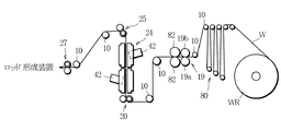
図7は、シート材Sとして紙または不織布からなるウエブを供給する供給装置の一例が示されている。この供給装置はウエブロールWRを備え、ウエブロールWRからウエブWが繰出し経路8に沿って繰出し可能となっている。すなわち、繰出し経路8にはフィードローラユニット19が配置され、フィードローラユニット19とウエブロールWRとの間にダンサローラ80が配置されている。そして、フィードローラユニット19の直下流には繰出し経路8を挟んで一対のクリープローラ82が回転可能に配置されている。これらクレープローラ82は互いにギャップを存して噛み合う櫛歯ローラからなる。一対のクレープローラ82はウエブWが通過する際、ウエブWに縦皺を付け、これにより、ウエブWは皺付きのシート材Sに形成される。この後、皺付きのシート材Sは前述したノズル装置24を通過する際、霧化バインダ液の塗布を受け、この後、ロッド成形装置4に向けて供給される。
【0049】
【発明の効果】
請求項1〜6のフィルタ製造機は、シート材の繰出し経路における垂直部分の両側でかつ上下隣接してスプレーノズルがそれぞれ配置され、しかも、各スプレーノズルにおける個々の噴出孔に要求される粒子の散布面積もまた少ないことから、高い粘度のバインダ液であっても、バインダ液の噴射圧を低く抑えることができる。この結果、各スプレーノズルは、個々の噴出孔からの粒子の散布面積を容易に制御することができ、シート材の両面にバインダ液を均一に塗布することができるばかりでなく、バインダ液の飛散を防止することができる。
【図面の簡単な説明】
【図1】 本発明の一実施例に係るフィルタ製造機を概略的に示した図である。
【図2】 図1の一対のスプレーノズルおよびその周辺の詳細を示した図である。
【図3】 スプレーノズルの斜視図である。
【図4】 図3のスプレーノズルの一部を拡大して示した図である。
【図5】 スプレーノズルの1つの噴出孔周辺を示した断面図である。
【図6】 スプレーノズルからシート材にバインダ液が塗布された状態を示す斜視図である。
【図7】 フィルタ製造機の変形例を概略的に示した図である。
【符号の説明】
4 ロッド成形装置
6 貯蔵容器
8 繰出し経路
12 1次バンディングジェット(開繊手段)
13 2次バンディングジェット(開繊手段)
18 3次バンディングジェット(開繊手段)
19 フィードローラユニット(送出手段)
21 4次バンディングジェット(開繊手段)
24 スプレー装置
42 スプレーノズル
44 噴出孔
50 バインダ液タンク(供給源)
51 ギヤポンプ
52 エア噴出スリット(エア噴出口)
58 エアコンプレッサ(圧縮空気源)
59 ヒータ
60 カバー装置
62 フロントカバー
64 バックカバー
66 通気口(抑制手段)
82 クリープローラ(皺付け手段)
WR ウエブローラ [0001]
BACKGROUND OF THE INVENTION
The present invention relates to a filter manufacturing machine for manufacturing a filter rod used as a filter plug of a filter cigarette.
[0002]
[Prior art]
This type of filter manufacturing machine is disclosed in, for example, Japanese Patent Laid-Open No. 7-203935. This known manufacturing machine includes a storage container that stores tow made of filter fibers, and the tow is fed from the storage container along a predetermined feeding path. In the process of feeding the tow, the tow is subjected to a fiber opening process to be spread and formed into a sheet material. Thereafter, the sheet material is subjected to the addition of a plasticizer such as triacetin and is supplied to the rod forming apparatus. The rod forming apparatus wraps the rod-shaped sheet material with paper while forming the sheet material into a rod shape, and continuously forms the filter rod.
[0003]
In the filter rod, the tow filter fibers are bonded to each other by the plasticizer, so that the external shape of the filter rod is stably maintained. The hardness of the filter rod is determined by the amount of plasticizer added, that is, the bonding strength between the filter fibers. Therefore, regarding the manufacture of this type of filter rod, it is necessary to uniformly add a plasticizer to the entire surface of the sheet material in order to stabilize the hardness of the filter rod. Conventionally, various methods such as a brush application method, a roller transfer method, and a nozzle injection method have been adopted for adding a plasticizer. When the plasticizer is triacetin, the brush application method and the roller transfer method are used for adding triacetin. Is frequently used.
[0004]
[Problems to be solved by the invention]
By the way, when triacetin is used as a plasticizer, triacetin dissolves the surface of the filter fiber and is absorbed into the filter fiber to form a joint between the filter fibers, and the adhesive strength of the joint is strong. Therefore, a filter rod using triacetin as a plasticizer, more specifically, a filter plug of a filter cigarette obtained by cutting the filter rod has poor degradability even if left in water.
[0005]
On the other hand, instead of triacetin, polyethylene glycol (PEGWhen a water-soluble material such as) is used as a binder, the filter plug is highly decomposable. However, used as a binderPEGIs liquid only when heated like hot melt adhesive, and it is liquidPEGThe viscosity of is very high compared to triacetin.
[0006]
Conventionally, since the nozzle used for plasticizer injection has a low injection pressure, only a relatively low-viscosity liquid plasticizer can be injected.PEGHigh viscosity etc.Binder liquidCan not be injected well.
On the other hand, if the injection pressure of the nozzle is increased, the nozzle has a certain degree of viscosityBinder liquidCan also be injected. However, in this case, from the nozzle to the sheet materialBinder liquidIs not uniformly added, the filter rod has non-uniform hardness. Also,Binder liquidIs scattered on the machine part around the nozzle in the filter manufacturing machine.Binder liquidIt becomes difficult to maintain a stable operation of the filter manufacturing machine.
[0007]
The object of the present invention is high viscosityBinder liquidBut it can be applied evenly to the sheet material andBinder liquidAn object of the present invention is to provide a filter manufacturing machine that can effectively prevent the scattering of water.
[0008]
[Means for Solving the Problems]
In order to achieve the above object, a filter manufacturing machine according to the present invention includes a feeding device that continuously feeds a sheet material including filter fibers along a feeding path, and a sheet material on the feeding path.Binder liquid for binding filter fibersAnd a rod forming device that is connected to the end of the feeding path, wraps the sheet material with paper while forming it into a rod shape, and continuously forms the filter rod.And the delivery path has a vertical portion extending in the vertical direction, The position isIncluding two spray nozzles disposed on both sides of the vertical portion of the feeding path and adjacent to each other, each spray nozzle extending in the width direction of the sheet material;Binder liquidAre provided in the vicinity of the row of ejection holes for ejecting the jet and the row of ejection holes, and are ejected from the ejection holesBinder liquidA plurality of air jets for jetting compressed air toward(Claim 1), This was subdivided by compressed airBinder liquidParticles ofTheIn the form of mist or drops,On the vertical partSheet materialCorresponding surfaceScattered towardsDo.
[0009]
According to the spray device of the filter manufacturing machine described above,In each spray nozzleHigh viscosity due to the small particle spraying area required for each nozzleBinder liquidEvenBinder liquidThe injection pressure can be kept low. As a result,Each spray nozzleFrom the individual ventsofEasy to control the particle spray area,Binder liquidNot only can be applied uniformly,Binder liquidPrevent splashes.Moreover, since each spray nozzle is arranged on both sides of the vertical part in the feeding path and adjacent to each other, the application conditions of the binder liquid to the sheet material are the same, and the binder liquid is uniformly applied to both surfaces of the sheet material. To do.
[0010]
More details, BaInda fluid can contain polyethylene glycol(Claim 6). Since polyethylene glycol is not only excellent in the binding strength of filter fibers, but also has no adverse effect on the taste of cigarettes, a filter rod suitable for cigarettes can be obtained. Further, the binder liquid may be a mixture of polyethylene glycol and a desired fragrance.
[0011]
Specifically, the spray device, BaThere is a pump that pressurizes the inda liquid and supplies the pressurized binder liquid toward the ejection holes.Of binder liquidSupply compressed air toward the supply source and air outletAndHas a heater to heat the compressed airdidCompressed air source and particles sprayed from spray nozzlespreadCover that encloses the area from the outsideapparatusAndMoreCan include(Claim 3).
[0012]
Since the above-described spray device includes the pump that pumps the binder liquid, the binder liquid can be reliably supplied to the ejection holes even if the binder liquid has a high viscosity. Moreover, since the compressed air ejected from the air outlet is heated, the compressed air prevents a decrease in the temperature of the binder liquid in the spray nozzle, that is, an increase in the viscosity of the binder liquid.Shi, Promote the fragmentation of the binder liquid. As a result, the spray device can more uniformly apply the binder liquid to the sheet material. In addition, coverapparatusReliably prevents the scattering of the binder liquid.
[0013]
The feeding device described above includes a storage container that stores tow made of filter fibers, a feeding means that sends tow from the storage container along a feeding path, and a tow that is opened in a lateral direction in the tow feeding process. And opening means for forming the sheet material.(Claim 4). In this case, the filter manufacturing machine manufactures a normal type filter rod.
[0014]
On the other hand, the feeding device is not limited to the one that forms the sheet material from the tows of the filter fibers. For example, the feeding device includes a web roll around which a paper or non-woven web made of filter fibers is wound, a feeding means for feeding the web along a feeding path from the web roll, and a vertical direction on the web in the web feeding process. And a brazing means for forming a web into a sheet material with a flange.(Claim 5). In this case, the spray device applies the binder liquid to the sheet material with the hook..
[0015]
The spray nozzle is used to spread the particles through the sheet material, that is,spreadregionAnd with the sheet material in betweenIt has a head part on the spray nozzle side and a tail part opposite to the spray nozzle side.Form a spreading area of the particles,In this case, the cover mentioned aboveapparatusIsspreadA front cover that surrounds the head portion of the area from the outside,spreadBack cover to confine the tail part of the area outside, and in the back coverspreadSuppression means for suppressing disturbance of the tail portion in the region(Claim 6).
[0016]
The front cover and back cover reliably prevent the binder liquid from splashing, while the suppression means is on the spray nozzle side.spreadThe head portion of the region is stabilized, and as a result, the application of the binder liquid to the sheet material becomes more uniform.
[0017]
DETAILED DESCRIPTION OF THE INVENTION
FIG.The filter manufacturing machine is roughly divided into a tow processing device 2 and a rod forming device 4. The tow processing apparatus 2 includes a
[0018]
More specifically, the
[0019]
Further, a
[0020]
When the
[0021]
The aforementioned primary to
[0022]
Second and third
here,FIG.As can be seen from the above, the second
[0023]
Here, each roller of the first to third nip
[0024]
The end of the
When the
[0025]
The rod forming device 4 includes a regulator (not shown) that adjusts the temperature of the compressed air to be supplied to the
[0026]
The
[0027]
Here, the
On the other hand, the
[0028]
Here, the
[0029]
Thereafter, the paper P and the rod-shaped sheet material S pass through the forming
[0030]
FIG., The
The
Each
[0031]
FIG.andFIG.As shown in FIG. 4, the
A plurality of air ejection slits 52 are opened above and below the row of ejection holes 44, respectively. These air ejection slits 52 extend in parallel with the row of ejection holes 44 and are arranged between the air ejection slits 52 adjacent in the horizontal direction. A predetermined interval is secured.
[0032]
FIG.Shows a cross section of one
Specifically, the source of the binder liquid isFIG.As shown in FIG. 4, a
[0033]
In this embodiment, polyethylene glycol (PEG) is used as the binder liquid. PEG not only has excellent binding strength of filter fibers, but also has a function of accelerating the decomposition of the filter plug when put in water. Various forms of PEG are known, ranging from liquid to hard wax, but the PEG in this example is solid at room temperature, but is heated and melted above the freezing point to form a binder liquid. used. Such a binder solution made of PEG has a viscosity over a wide range of several tens to 30,000 mPa · s. However, the higher the viscosity of the binder solution, the better the binder effect (high binding strength of the filter fibers).
[0034]
The binder liquid is not limited to PEG, and other known adhesives such as polyalkylene oxide resins and polyvinyl alcohol resins other than PEG, and water-soluble polymers and thermoplastic polymers can be used. Further, the binder liquid may contain a desired fragrance.
The
[0035]
on the other hand,FIG.As shown, each air ejection slit 52 has an
FIG.As shown in FIG. 2, the compressed air source includes an
[0036]
When the atomized binder liquid is sprayed toward the sheet material S from the number of ejection holes 44 corresponding to the width of the sheet material S,FIG.As shown in FIG. 5, the binder liquid is uniformly applied to both sides of the sheet material S. As a result, the filter rod FR molded from the sheet material S has a stable hardness.
Further, since the number of the ejection holes 44 is set according to the width of the sheet material S, the injection pressure required for the injection of the binder liquid can be kept low even if the viscosity of the binder liquid is high. As a result, since the injection pressure of the binder liquid is low, the spray area of the atomized binder liquid from each
[0037]
Furthermore, since each
[0038]
The
FIG., The
[0039]
The
[0040]
On the other hand, a
[0041]
A shielding
Further,
[0042]
FIG.As shown in FIG. 4, the atomized binder liquid sprayed from the
The
[0043]
Further, since the vent holes 66 are distributed on the other side wall of the
[0044]
On the other hand, the
The binder liquid received by the shielding
[0045]
The present invention is not limited to the above-described embodiment, and various modifications can be made. For example, the pair of
[0046]
Moreover, the
And the filter manufacturing machine of this invention is applicable not only to manufacture of a plain filter rod but to manufacture of a charcoal filter rod. In this case, a charcoal particle spraying device is disposed at the end of the
[0047]
The sheet material S is not limited to a tow made of only cellulose acetate fibers, but may be a sheet material made of another material or a mixture of both. More specifically, such other materials include natural or semi-synthetic materials (eg, pulp, linter, cotton, hemp, viscose rayon, copper ammonia rayon, wool, etc., or microbial production systems such as polyhydroxyalkanoates) Biodegradable biopolymers), normal synthetic materials (eg polyolefins such as polypropylene, polyesters such as polyethylene terephthalate, polyamides), biodegradable biosynthetic materials (eg polylactic acid, polycaprolactone, polybutylene succinate, polyvinyl alcohol) ), Known materials such as photodegradable biomaterials can be used. These other materials can be produced in the form of a web such as tow, non-woven fabric or paper by mixing alone or in combination of two or more.
[0048]
FIG.Shows an example of a supply device for supplying a web made of paper or non-woven fabric as the sheet material S. This supply device includes a web roll WR, and the web W can be fed out along the
[0049]
【The invention's effect】
In the filter manufacturing machine according to any one of claims 1 to 6, spray nozzles are arranged on both sides of the vertical portion in the sheet material feeding path and adjacent to each other in the vertical direction. Since the spray area is also small, the injection pressure of the binder liquid can be kept low even with a binder liquid having a high viscosity. As a result, each spray nozzle can easily control the spraying area of the particles from the individual ejection holes, not only can the binder liquid be uniformly applied to both sides of the sheet material, but also the scattering of the binder liquid. Can be prevented.
[Brief description of the drawings]
FIG. 1 is a diagram schematically showing a filter manufacturing machine according to an embodiment of the present invention.It is.
[Figure 2]FIG.Figure showing details of a pair of spray nozzles and their surroundingsIt is.
[Fig. 3] Perspective view of spray nozzleIt is.
[Fig. 4]FIG.Figure showing an enlarged view of a part of the spray nozzleIt is.
FIG. 5 is a sectional view showing the vicinity of one spray hole of a spray nozzleIt is.
FIG. 6 is a perspective view showing a state in which a binder liquid is applied to a sheet material from a spray nozzle.It is.
FIG. 7 is a diagram schematically showing a modification of the filter manufacturing machine.
[Explanation of symbols]
4 Rod forming equipment
6 Storage container
8 Feeding route
12 Primary banding jet (opening means)
13 Secondary banding jet (opening means)
18 3rd banding jet (opening means)
19 Feed roller unit (feeding means)
21 4th banding jet (opening means)
24 spray equipment
42 Spray nozzle
44 ejection hole
50 Binder liquid tank (supply source)
51 Gear pump
52 Air outlet slit (Air outlet)
58 Air compressor (compressed air source)
59 Heater
60 Cover device
62 Front cover
64 Back cover
66 Vent (Suppression means)
82 Creep roller (brazing means)
WR web roller
Claims (6)
前記繰出し経路上の前記シート材に前記フィルタ繊維を結合するバインダ液を塗布するスプレー装置と、
前記繰出し経路の終端に接続され、前記シート材を棒状に成形しながら紙により包み込み、フィルタロッドを連続的に成形するロッド成形装置と
を具備し、
前記繰出し経路は垂直方向に延びる垂直部分を有し、
前記スプレー装置は、前記繰出し経路の前記垂直部分の両側で且つ上下に隣接して配置された2つのスプレーノズルを含み、
前記各スプレーノズルは、前記シート材の幅方向に延び、前記バインダ液を噴射する噴出孔の列と、前記噴出孔の列の近傍に設けられ、前記噴出孔から噴射される前記バインダ液に向けて圧縮空気を噴出する複数のエア噴出口とを有し、これにより、前記圧縮空気により細分化された前記バインダ液の粒子を前記垂直部分上の前記シート材の対応する面に向けて散布する、フィルタ製造機。A feeding device that continuously feeds the sheet material including the filter fiber along the feeding path;
And spray equipment for applying the binder solution to bind the filter fibers in the sheet material on the feeding path,
A rod forming device connected to the end of the feeding path, wrapped in paper while forming the sheet material into a rod shape, and continuously forming a filter rod ;
The delivery path has a vertical portion extending in a vertical direction;
The spray device includes two spray nozzles disposed on both sides of the vertical portion of the feeding path and adjacent to each other vertically.
Each of the spray nozzles extends in the width direction of the sheet material and is provided in the vicinity of the row of ejection holes for ejecting the binder liquid and the row of the ejection holes, toward the binder liquid ejected from the ejection holes. A plurality of air outlets for jetting compressed air, whereby the particles of the binder liquid subdivided by the compressed air are dispersed toward the corresponding surface of the sheet material on the vertical portion. , Filter making machine.
前記エア噴出口に向けて圧縮空気を供給し、前記圧縮空気を加熱するヒータを有した前記圧縮空気源と、および
前記スプレーノズルから散布される前記粒子の広がり領域を外側から囲むカバー装置と
更に含む請求項1のフィルタ製造機。It said spray device includes a source of a pre-Symbol binder liquid pressurized and pressurized binder solution have a pump for supplying toward the ejection holes of the spray nozzle binder solution,
The supply compressed air toward the air ejection port, and the compressed air the compressed air source have a heater for heating the, and cover enclosing the spread area of the particles sprayed from the spray nozzle from the outer device
The filter manufacturing machine according to claim 1 , further comprising:
フィルタ繊維からなるトウを貯蔵した貯蔵容器と、
前記貯蔵容器から前記繰出し経路に沿って前記トウを送出する送出手段と、
前記トウの送出過程にて、前記トウを横方向に開繊してシート材に形成する開繊手段と
を含む、請求項1又は2に記載のフィルタ製造機。The feeding device is
A storage container storing tow made of filter fibers;
A delivery means for delivering the tow from the storage container along the delivery path;
At delivery process of the tow, and a open Senshu stage for forming the sheet material by spreading the tow laterally filter manufacturing machine according to claim 1 or 2.
フィルタ繊維からなる紙又は不織布のウエブが巻回されたウエブロールと、
前記ウエブロールから前記繰出し経路に沿って前記ウエブを送出する送出手段と、
前記ウエブの送出過程にて、前記ウエブに縦皺を付与し、前記ウエブを皺付きのシート材に形成する皺付け手段と
を含む、請求項1又は2に記載のフィルタ製造機。The feeding device is
A web roll on which a paper or nonwoven web made of filter fibers is wound;
A delivery means for delivering the web from the web roll along the delivery path;
Wherein at web-out process, the web to impart vertical wrinkles, and a wrinkle with means for forming the web to the sheet material with a wrinkled, filter manufacturing machine according to claim 1 or 2.
前記カバー装置は、
前記広がり領域の前記ヘッド部分を外側から囲むフロントカバーと、
前記広がり領域の前記テール部分を外側から閉じ込めるバックカバーと、
前記バックカバー内にて、前記広がり領域の前記テール部分の乱れを抑制する抑制手段と
を含む、請求項3に記載のフィルタ製造機。It said spray nozzle is a spread area of the particles penetrating the sheet material, and the head portion of the spray nozzle side across the sheet material, and the spray nozzle side and a tail portion opposite to Forming a spreading region of the particles;
The cover device is
A front cover surrounding the head portion of the spreading area from the outside;
A back cover for confining the tail portion of the spreading area from the outside;
The filter manufacturing machine according to claim 3, further comprising suppression means for suppressing disturbance of the tail portion of the spreading area in the back cover.
Applications Claiming Priority (2)
| Application Number | Priority Date | Filing Date | Title |
|---|---|---|---|
| JP2000263710 | 2000-08-31 | ||
| PCT/JP2001/007427 WO2002017738A1 (en) | 2000-08-31 | 2001-08-29 | Filter manufacturing machine |
Publications (1)
| Publication Number | Publication Date |
|---|---|
| JP4098079B2 true JP4098079B2 (en) | 2008-06-11 |
Family
ID=18751217
Family Applications (1)
| Application Number | Title | Priority Date | Filing Date |
|---|---|---|---|
| JP2002522723A Expired - Fee Related JP4098079B2 (en) | 2000-08-31 | 2001-08-29 | Filter making machine |
Country Status (7)
| Country | Link |
|---|---|
| US (1) | US6908421B2 (en) |
| EP (1) | EP1314363B1 (en) |
| JP (1) | JP4098079B2 (en) |
| CN (1) | CN1265743C (en) |
| AU (1) | AU2001282537A1 (en) |
| DE (1) | DE60142908D1 (en) |
| WO (1) | WO2002017738A1 (en) |
Cited By (1)
| Publication number | Priority date | Publication date | Assignee | Title |
|---|---|---|---|---|
| KR101886690B1 (en) * | 2016-11-16 | 2018-08-08 | 주식회사 이엠코 | Dust collecting filter and dust collector |
Families Citing this family (31)
| Publication number | Priority date | Publication date | Assignee | Title |
|---|---|---|---|---|
| DE10354924B4 (en) * | 2003-11-25 | 2024-01-18 | Körber Technologies Gmbh | Device for processing filter tow material and device for producing filters |
| WO2005087026A1 (en) * | 2004-03-16 | 2005-09-22 | Japan Tobacco Inc. | Filter rod manufacturing machine |
| DE102004021773B4 (en) * | 2004-04-30 | 2007-02-22 | Hauni Maschinenbau Ag | Scraper and sprayer for filter tow |
| DE102005015877A1 (en) * | 2005-04-06 | 2006-10-12 | Hauni Maschinenbau Ag | Method and device for applying triacetin to a filter material web |
| DE102006018101A1 (en) | 2006-04-18 | 2007-10-25 | Hauni Maschinenbau Ag | Processing unit for processing at least one filter tow strip and a device with at least two such processing units |
| ITBO20060646A1 (en) * | 2006-09-20 | 2006-12-20 | Gd Spa | MACHINE FOR THE PRODUCTION OF CIGARETTE FILTERS |
| US7878210B2 (en) * | 2007-06-04 | 2011-02-01 | Philip Morris Usa Inc. | Cellulose acetate fiber modification |
| JP2009112276A (en) * | 2007-11-08 | 2009-05-28 | Japan Filter Technology Ltd | Rod-forming machine |
| DE102007057396A1 (en) | 2007-11-27 | 2009-05-28 | Hauni Maschinenbau Ag | Device for processing at least two filter tows |
| DE102008005185A1 (en) | 2008-01-18 | 2009-07-30 | Hauni Maschinenbau Aktiengesellschaft | Device for transporting tow |
| DE102009022790A1 (en) | 2009-05-27 | 2010-12-02 | Hauni Maschinenbau Aktiengesellschaft | Apparatus for processing filter bowl line in tobacco processing industry, has filter bowl guide path, along which filter bowl line is guided in transport direction |
| GB0922253D0 (en) * | 2009-12-21 | 2010-02-03 | British American Tobacco Co | Sheet filter materials with additives |
| WO2011114440A1 (en) * | 2010-03-16 | 2011-09-22 | 日本たばこ産業株式会社 | Filter manufacturing machine |
| GB201007946D0 (en) * | 2010-05-12 | 2010-06-30 | British American Tobacco Co | Filter additive |
| CN101898182B (en) * | 2010-07-13 | 2012-07-04 | 长沙湖大江远系统集成有限公司 | Method and device for adding plasticizer on loosened fiber tow belt |
| JP2013542063A (en) * | 2010-09-20 | 2013-11-21 | ブレントナール,ニコラス | Filter and manufacturing method |
| WO2012114437A1 (en) * | 2011-02-21 | 2012-08-30 | 日本たばこ産業株式会社 | Cigarette filter manufacturing device and cigarette filter manufacturing method |
| EP2723201B1 (en) | 2011-06-23 | 2018-08-08 | British American Tobacco (Investments) Ltd | Filter material comprising polylactide fibres |
| WO2013124984A1 (en) * | 2012-02-22 | 2013-08-29 | 日本たばこ産業株式会社 | Device for adding to filter tow |
| US20150059789A1 (en) * | 2012-02-23 | 2015-03-05 | Anthony Denis McCormack | Tobacco smoke filter |
| ITBO20120106A1 (en) * | 2012-03-05 | 2013-09-06 | Montrade Srl | METHOD AND MACHINE FOR THE PRODUCTION OF FILTERS WITHOUT PAPER FOR SMOKE ITEMS |
| GB201401520D0 (en) * | 2014-01-29 | 2014-03-12 | Batmark Ltd | Aerosol-forming member |
| UA116855C2 (en) * | 2014-07-18 | 2018-05-10 | Джапан Тобакко Інк. | Apparatus and method for producing cigarette filter |
| KR102226828B1 (en) * | 2014-07-22 | 2021-03-12 | 제이티 인터내셔널 소시에떼 아노님 | Method and appratus for forming a filter rod |
| DE102014221146A1 (en) * | 2014-10-17 | 2016-04-21 | Hauni Maschinenbau Ag | Transfer device of a filter rod machine and method for operating a filter rod machine of the tobacco processing industry |
| TR201819930T4 (en) * | 2015-02-18 | 2019-01-21 | Jt Int Sa | High Additive Filters for Tobacco Smoking Products |
| ITUB20160197A1 (en) * | 2016-01-21 | 2017-07-21 | Gd Spa | Packaging machine for cigarette filters and method for packaging cigarette filters. |
| DE102019106146A1 (en) * | 2019-03-11 | 2020-09-17 | Illinois Tool Works Inc. | NOZZLE ARRANGEMENT FOR APPLYING FLUIDS, SYSTEM WITH SUCH NOZZLE ARRANGEMENT AND METHOD FOR APPLYING FLUIDS |
| CN110477450B (en) * | 2019-08-28 | 2023-07-11 | 深圳市智叶科技有限公司 | Filter tip for electronic cigarette and preparation method thereof |
| CN115074886A (en) * | 2021-03-11 | 2022-09-20 | 株式会社大赛璐 | Tow open fiber body manufacturing device and tow open fiber body manufacturing method |
| DE102022116185A1 (en) * | 2022-06-29 | 2024-01-04 | Körber Technologies Gmbh | Machine and process in the tobacco processing industry for producing a rod or paper filter and use of the machine |
Family Cites Families (20)
| Publication number | Priority date | Publication date | Assignee | Title |
|---|---|---|---|---|
| USRE28487E (en) * | 1953-08-04 | 1975-07-22 | Crimped flat material for filter plugs | |
| US3774508A (en) * | 1968-05-08 | 1973-11-27 | American Filtrona Corp | Apparatus for making filter means |
| DE2017360C3 (en) * | 1970-04-11 | 1979-05-23 | Hauni-Werke Koerber & Co Kg, 2050 Hamburg | Method and machine for the production of rod-shaped articles for the tobacco processing industry |
| DE2036486A1 (en) * | 1970-07-23 | 1972-02-03 | Hauni-Werke Körber & Co KG, 2050 Hamburg | Method for peeling off a dewstrip for cigarette filters |
| DE2127293C3 (en) * | 1971-06-02 | 1980-07-31 | Hauni-Werke Koerber & Co Kg, 2050 Hamburg | Device for applying a plasticizer to a continuous strip of spread filter rope for the manufacture of filters for rod-shaped articles in the tobacco processing industry |
| US3847064A (en) * | 1972-09-11 | 1974-11-12 | American Filtrona Corp | Tobacco smoke filter |
| US4179323A (en) * | 1973-08-27 | 1979-12-18 | Liggett Group Inc. | Method for making a hollow filter rod |
| GB1463114A (en) * | 1974-01-28 | 1977-02-02 | Rothmans Of Pall Mall | Method and apparatus for the opening of tow |
| GB2020158B (en) * | 1978-04-21 | 1982-11-24 | Cigarette Components Ltd | Production of tobacco smoke filters |
| GB2075373A (en) * | 1980-04-24 | 1981-11-18 | Hauni Werke Koerber & Co Kg | Applying additive to tobacco |
| US4537583A (en) * | 1983-02-18 | 1985-08-27 | R. J. Reynolds Tobacco Company | Method and apparatus for conveying filter tow |
| US4549875A (en) * | 1983-06-02 | 1985-10-29 | R. J. Reynolds Tobacco Co. | Manufacture of tobacco smoke filters |
| US5163452A (en) * | 1990-09-20 | 1992-11-17 | R. J. Reynolds Tobacco Company | Rod making apparatus for use in the manufacture of smoking articles |
| JPH06327455A (en) | 1993-05-26 | 1994-11-29 | Japan Tobacco Inc | Tobacco filter production unit having netty guide pipe |
| AU7717794A (en) * | 1993-09-02 | 1995-03-22 | Weyerhaeuser Company | Spray applicator for coating substrates uniformly |
| DE4340029A1 (en) | 1993-11-24 | 1995-06-01 | Hauni Werke Koerber & Co Kg | Arrangement for preparing a strip of filter material |
| JP3229763B2 (en) | 1995-01-11 | 2001-11-19 | ダイセル化学工業株式会社 | Manufacturing method of tobacco filter |
| US5902540A (en) * | 1996-10-08 | 1999-05-11 | Illinois Tool Works Inc. | Meltblowing method and apparatus |
| JP2000083642A (en) | 1998-09-14 | 2000-03-28 | Mitsubishi Rayon Co Ltd | Manufacturing equipment for tobacco filter |
| DE19853833A1 (en) | 1998-11-21 | 2000-05-25 | Hauni Maschinenbau Ag | Method and arrangement for gluing a wrapping strip for a filler in the tobacco processing industry |
-
2001
- 2001-08-29 CN CNB018165710A patent/CN1265743C/en not_active Expired - Fee Related
- 2001-08-29 US US10/362,926 patent/US6908421B2/en not_active Expired - Lifetime
- 2001-08-29 EP EP01961172A patent/EP1314363B1/en not_active Expired - Lifetime
- 2001-08-29 DE DE60142908T patent/DE60142908D1/en not_active Expired - Lifetime
- 2001-08-29 AU AU2001282537A patent/AU2001282537A1/en not_active Abandoned
- 2001-08-29 WO PCT/JP2001/007427 patent/WO2002017738A1/en active Application Filing
- 2001-08-29 JP JP2002522723A patent/JP4098079B2/en not_active Expired - Fee Related
Cited By (1)
| Publication number | Priority date | Publication date | Assignee | Title |
|---|---|---|---|---|
| KR101886690B1 (en) * | 2016-11-16 | 2018-08-08 | 주식회사 이엠코 | Dust collecting filter and dust collector |
Also Published As
| Publication number | Publication date |
|---|---|
| CN1265743C (en) | 2006-07-26 |
| EP1314363A1 (en) | 2003-05-28 |
| AU2001282537A1 (en) | 2002-03-13 |
| CN1466425A (en) | 2004-01-07 |
| WO2002017738A1 (en) | 2002-03-07 |
| US20030173418A1 (en) | 2003-09-18 |
| DE60142908D1 (en) | 2010-10-07 |
| EP1314363A4 (en) | 2008-07-09 |
| EP1314363B1 (en) | 2010-08-25 |
| US6908421B2 (en) | 2005-06-21 |
Similar Documents
| Publication | Publication Date | Title |
|---|---|---|
| JP4098079B2 (en) | Filter making machine | |
| KR101425111B1 (en) | Device for manufacturing spread long fiber tow | |
| US4476807A (en) | Apparatus for application of additives to cigarette filter tow | |
| JP5388249B2 (en) | Filter making machine | |
| US4646675A (en) | Apparatus for applying fluid additive to fibrous material | |
| JP5450246B2 (en) | Manufacturing method of spread product of long fiber tow and manufacturing apparatus therefor | |
| US7261681B2 (en) | Method and apparatus for applying additive to a moving, spread-out filter material web | |
| CN202697694U (en) | Gluing unit for continuous paper web | |
| JP2007031865A (en) | Non-contact type controller for filamentous body and method for controlling | |
| US7107659B2 (en) | Method and apparatus for making an absorbent composite | |
| JP5888800B2 (en) | Filter rod manufacturing machine and filter rod manufacturing method | |
| EP3170411A1 (en) | Apparatus and method for producing cigarette filter | |
| US4414253A (en) | Method for applying liquid plasticizer to filamentary filter material | |
| JP3002173B2 (en) | Manufacturing method and device for tobacco filter | |
| CN113163854A (en) | Tubular element with thread for use with an aerosol-generating article | |
| SK281388B6 (en) | Process for preparing mineral fibre elements and apparatus for carrying out the process | |
| US7059027B2 (en) | Method and apparatus for making an absorbent composite | |
| US7076848B2 (en) | Method and apparatus for making an absorbent composite | |
| JP2004337159A (en) | Method for preparing cut fiber and apparatus for preparing the cut fiber used for producing filter | |
| CN113645858A (en) | Heating cigarette, heating cigarette product, method for manufacturing tobacco rod in heating cigarette, and manufacturing device | |
| EP1886589B1 (en) | A device for the treatment of filter material used in tobacco products | |
| EP3828337A1 (en) | Fiber assembly-forming method, fiber assembly-forming apparatus, and sheet | |
| EP1670382A2 (en) | Method and apparatus for making an absorbent composite | |
| WO2023162217A1 (en) | Additive adding unit, filler element manufacturing device equipped with said adding unit, additive adding method, and filler element manufacturing method using said adding method | |
| CN212520771U (en) | Atomizing perfuming device, atomizing perfuming equipment and forming machine |
Legal Events
| Date | Code | Title | Description |
|---|---|---|---|
| A621 | Written request for application examination |
Free format text: JAPANESE INTERMEDIATE CODE: A621 Effective date: 20050819 |
|
| A131 | Notification of reasons for refusal |
Free format text: JAPANESE INTERMEDIATE CODE: A131 Effective date: 20070725 |
|
| A521 | Written amendment |
Free format text: JAPANESE INTERMEDIATE CODE: A523 Effective date: 20070925 |
|
| TRDD | Decision of grant or rejection written | ||
| A01 | Written decision to grant a patent or to grant a registration (utility model) |
Free format text: JAPANESE INTERMEDIATE CODE: A01 Effective date: 20080305 |
|
| A61 | First payment of annual fees (during grant procedure) |
Free format text: JAPANESE INTERMEDIATE CODE: A61 Effective date: 20080312 |
|
| R150 | Certificate of patent or registration of utility model |
Ref document number: 4098079 Country of ref document: JP Free format text: JAPANESE INTERMEDIATE CODE: R150 Free format text: JAPANESE INTERMEDIATE CODE: R150 |
|
| FPAY | Renewal fee payment (event date is renewal date of database) |
Free format text: PAYMENT UNTIL: 20110321 Year of fee payment: 3 |
|
| FPAY | Renewal fee payment (event date is renewal date of database) |
Free format text: PAYMENT UNTIL: 20120321 Year of fee payment: 4 |
|
| R250 | Receipt of annual fees |
Free format text: JAPANESE INTERMEDIATE CODE: R250 |
|
| FPAY | Renewal fee payment (event date is renewal date of database) |
Free format text: PAYMENT UNTIL: 20130321 Year of fee payment: 5 |
|
| R250 | Receipt of annual fees |
Free format text: JAPANESE INTERMEDIATE CODE: R250 |
|
| FPAY | Renewal fee payment (event date is renewal date of database) |
Free format text: PAYMENT UNTIL: 20140321 Year of fee payment: 6 |
|
| R250 | Receipt of annual fees |
Free format text: JAPANESE INTERMEDIATE CODE: R250 |
|
| R250 | Receipt of annual fees |
Free format text: JAPANESE INTERMEDIATE CODE: R250 |
|
| R250 | Receipt of annual fees |
Free format text: JAPANESE INTERMEDIATE CODE: R250 |
|
| R250 | Receipt of annual fees |
Free format text: JAPANESE INTERMEDIATE CODE: R250 |
|
| R250 | Receipt of annual fees |
Free format text: JAPANESE INTERMEDIATE CODE: R250 |
|
| R250 | Receipt of annual fees |
Free format text: JAPANESE INTERMEDIATE CODE: R250 |
|
| LAPS | Cancellation because of no payment of annual fees |