JP4096014B2 - Ultrasonic inspection method and apparatus for reactor pressure vessel - Google Patents
Ultrasonic inspection method and apparatus for reactor pressure vessel Download PDFInfo
- Publication number
- JP4096014B2 JP4096014B2 JP2006215190A JP2006215190A JP4096014B2 JP 4096014 B2 JP4096014 B2 JP 4096014B2 JP 2006215190 A JP2006215190 A JP 2006215190A JP 2006215190 A JP2006215190 A JP 2006215190A JP 4096014 B2 JP4096014 B2 JP 4096014B2
- Authority
- JP
- Japan
- Prior art keywords
- ultrasonic
- container
- pressure vessel
- reactor pressure
- vessel
- Prior art date
- Legal status (The legal status is an assumption and is not a legal conclusion. Google has not performed a legal analysis and makes no representation as to the accuracy of the status listed.)
- Active
Links
Images


Classifications
-
- G—PHYSICS
- G01—MEASURING; TESTING
- G01N—INVESTIGATING OR ANALYSING MATERIALS BY DETERMINING THEIR CHEMICAL OR PHYSICAL PROPERTIES
- G01N29/00—Investigating or analysing materials by the use of ultrasonic, sonic or infrasonic waves; Visualisation of the interior of objects by transmitting ultrasonic or sonic waves through the object
- G01N29/04—Analysing solids
- G01N29/11—Analysing solids by measuring attenuation of acoustic waves
-
- G—PHYSICS
- G01—MEASURING; TESTING
- G01N—INVESTIGATING OR ANALYSING MATERIALS BY DETERMINING THEIR CHEMICAL OR PHYSICAL PROPERTIES
- G01N29/00—Investigating or analysing materials by the use of ultrasonic, sonic or infrasonic waves; Visualisation of the interior of objects by transmitting ultrasonic or sonic waves through the object
- G01N29/04—Analysing solids
- G01N29/06—Visualisation of the interior, e.g. acoustic microscopy
- G01N29/0609—Display arrangements, e.g. colour displays
-
- G—PHYSICS
- G01—MEASURING; TESTING
- G01N—INVESTIGATING OR ANALYSING MATERIALS BY DETERMINING THEIR CHEMICAL OR PHYSICAL PROPERTIES
- G01N29/00—Investigating or analysing materials by the use of ultrasonic, sonic or infrasonic waves; Visualisation of the interior of objects by transmitting ultrasonic or sonic waves through the object
- G01N29/22—Details, e.g. general constructional or apparatus details
- G01N29/26—Arrangements for orientation or scanning by relative movement of the head and the sensor
- G01N29/262—Arrangements for orientation or scanning by relative movement of the head and the sensor by electronic orientation or focusing, e.g. with phased arrays
-
- G—PHYSICS
- G21—NUCLEAR PHYSICS; NUCLEAR ENGINEERING
- G21C—NUCLEAR REACTORS
- G21C17/00—Monitoring; Testing ; Maintaining
- G21C17/003—Remote inspection of vessels, e.g. pressure vessels
-
- G—PHYSICS
- G01—MEASURING; TESTING
- G01N—INVESTIGATING OR ANALYSING MATERIALS BY DETERMINING THEIR CHEMICAL OR PHYSICAL PROPERTIES
- G01N2291/00—Indexing codes associated with group G01N29/00
- G01N2291/02—Indexing codes associated with the analysed material
- G01N2291/028—Material parameters
- G01N2291/02854—Length, thickness
-
- G—PHYSICS
- G01—MEASURING; TESTING
- G01N—INVESTIGATING OR ANALYSING MATERIALS BY DETERMINING THEIR CHEMICAL OR PHYSICAL PROPERTIES
- G01N2291/00—Indexing codes associated with group G01N29/00
- G01N2291/02—Indexing codes associated with the analysed material
- G01N2291/028—Material parameters
- G01N2291/02872—Pressure
-
- G—PHYSICS
- G01—MEASURING; TESTING
- G01N—INVESTIGATING OR ANALYSING MATERIALS BY DETERMINING THEIR CHEMICAL OR PHYSICAL PROPERTIES
- G01N2291/00—Indexing codes associated with group G01N29/00
- G01N2291/04—Wave modes and trajectories
- G01N2291/044—Internal reflections (echoes), e.g. on walls or defects
-
- G—PHYSICS
- G01—MEASURING; TESTING
- G01N—INVESTIGATING OR ANALYSING MATERIALS BY DETERMINING THEIR CHEMICAL OR PHYSICAL PROPERTIES
- G01N2291/00—Indexing codes associated with group G01N29/00
- G01N2291/26—Scanned objects
- G01N2291/267—Welds
- G01N2291/2675—Seam, butt welding
-
- Y—GENERAL TAGGING OF NEW TECHNOLOGICAL DEVELOPMENTS; GENERAL TAGGING OF CROSS-SECTIONAL TECHNOLOGIES SPANNING OVER SEVERAL SECTIONS OF THE IPC; TECHNICAL SUBJECTS COVERED BY FORMER USPC CROSS-REFERENCE ART COLLECTIONS [XRACs] AND DIGESTS
- Y02—TECHNOLOGIES OR APPLICATIONS FOR MITIGATION OR ADAPTATION AGAINST CLIMATE CHANGE
- Y02E—REDUCTION OF GREENHOUSE GAS [GHG] EMISSIONS, RELATED TO ENERGY GENERATION, TRANSMISSION OR DISTRIBUTION
- Y02E30/00—Energy generation of nuclear origin
- Y02E30/30—Nuclear fission reactors
Description
本発明は、超音波検査技術に係り、特に検査対象となる部分が原子炉圧力容器の容器貫通部である場合の超音波検査技術に関するものである。 The present invention relates to an ultrasonic inspection technique, and more particularly to an ultrasonic inspection technique in a case where a portion to be inspected is a vessel penetration portion of a reactor pressure vessel.
金属などの固体の非破壊検査方法として、超音波による手法(超音波検査方法あるいは超音波探傷方法)が従来から一般に用いられている。このうち、原子炉圧力容器の超音波検査方法として、従来以下のような検査方法が知られている。 As a nondestructive inspection method for solids such as metals, an ultrasonic method (an ultrasonic inspection method or an ultrasonic flaw detection method) has been generally used. Among these, the following inspection methods are conventionally known as an ultrasonic inspection method for a reactor pressure vessel.
例えば、特許文献1によれば、原子炉圧力容器の容器貫通部(原子炉圧力容器下鏡に取付けられた制御棒駆動機構部のスタブ溶接部)の内面に超音波探触子を配置し、貫通部の内面に水を入れ水浸法により探傷する方法が記載されている。
For example, according to
また、特許文献2によれば、原子炉炉内炉底部の容器貫通部(制御棒駆動機構のスタブ溶接部)に炉内すなわち原子炉圧力容器の内側に超音波探触子を配置し、容器貫通部(スタブ溶接部)を探傷する方法が記載されている。 Further, according to Patent Document 2, an ultrasonic probe is arranged in the reactor, that is, inside the reactor pressure vessel, in the vessel penetration portion (stub weld portion of the control rod drive mechanism) in the reactor bottom in the reactor, A method for flaw detection of a penetration portion (stub weld) is described.
上記に示した例のように、従来の原子炉圧力容器の容器貫通部の超音波検査では、原子炉圧力容器の容器貫通部の溶接部に対して、水などの接触媒質を介して超音波を伝播させる探傷方法が一般的であった。 As in the example shown above, in the ultrasonic inspection of the conventional reactor pressure vessel penetration through the vessel, the ultrasonic wave is passed through the contact medium such as water to the weld through the reactor penetration of the reactor pressure vessel. The flaw detection method that propagates was common.
原子炉圧力容器の容器貫通部における超音波検査対象は、オーステナイト系ステンレス鋼溶接金属やニッケル基合金溶接部の検査が想定される。 The ultrasonic inspection target in the vessel penetration portion of the reactor pressure vessel is assumed to be an inspection of an austenitic stainless steel weld metal or a nickel-base alloy weld.
原子炉圧力容器の容器貫通部に対する従来の超音波検査方法は、検査対象となる容器貫通部の溶接部近傍に超音波検査装置の超音波探触子を接近させて検査しているため超音波を効率的に検査対象部に伝播させることができるという利点を持っている。 In the conventional ultrasonic inspection method for the vessel penetration part of the reactor pressure vessel, the ultrasonic probe of the ultrasonic inspection apparatus is inspected close to the welded part of the vessel penetration part to be inspected. Can be efficiently propagated to the inspection target part.
しかし、原子炉圧力容器の容器貫通部の内面または、原子炉圧力容器の内面に超音波探触子を配置するためには、超音波探触子を水中で遠隔走査する必要があるため、超音波探触子の位置精度を充分に確保した探傷を行うことが困難であるという課題があった。 However, in order to place the ultrasonic probe on the inner surface of the reactor penetration part of the reactor pressure vessel or the inner surface of the reactor pressure vessel, it is necessary to remotely scan the ultrasonic probe in water. There was a problem that it was difficult to perform flaw detection with sufficiently secured position accuracy of the acoustic probe.
さらに、容器貫通部の溶接部表面は、グラインダなどで表面が機械加工で仕上げてある場合が多く、検査対象表面に粗さやうねりといった形状のばらつきが存在する。そのために、特許文献2にあるように、原子炉圧力容器の内側からの超音波検査では、検査対象への超音波の入射効率を一定に保つことができず、検査部位ごとに超音波検査の受信信号にばらつきが生じるために検査欠陥の評価が難しくなる場合がある。 Further, the surface of the welded portion of the container penetration portion is often finished by machining with a grinder or the like, and there are variations in shape such as roughness and undulation on the surface to be inspected. Therefore, as disclosed in Patent Document 2, in the ultrasonic inspection from the inside of the reactor pressure vessel, the incident efficiency of the ultrasonic wave to the inspection target cannot be kept constant, and the ultrasonic inspection is performed for each inspection region. Due to variations in received signals, it may be difficult to evaluate inspection defects.
従って、本発明が解決しようとする課題は、原子炉圧力容器の容器貫通部の溶接部の超音波検査において、超音波探触子の位置精度を極力確保し、且つ、検査対象となる溶接部表面の形状の影響を低減することにある。 Therefore, the problem to be solved by the present invention is to ensure the position accuracy of the ultrasonic probe as much as possible in the ultrasonic inspection of the welded portion of the reactor pressure vessel through-hole, and to be the inspection target It is to reduce the influence of the surface shape.
本発明の超音波検査方法は、超音波検査装置の超音波探触子から超音波を原子炉圧力容器に送信して前記原子炉圧力容器の容器貫通部からの前記超音波の反射波を前記超音波探触子で受信し、前記受信した前記反射波に基づくエコーを前記超音波検査装置の表示部に表示する超音波検査方法において、受信した前記反射波の強度に基づいて前記原子炉圧力容器の壁面に対する前記容器貫通部の傾斜角度を求める第1過程と、前記傾斜角度を有する、前記容器貫通部の円周方向位置を求める第2過程と、を備えたことを特徴とした超音波検査方法である。 In the ultrasonic inspection method of the present invention, an ultrasonic wave is transmitted from an ultrasonic probe of an ultrasonic inspection apparatus to a reactor pressure vessel, and the reflected wave of the ultrasonic wave from the vessel penetration portion of the reactor pressure vessel is received by the ultrasonic probe, the ultrasonic inspection method for displaying an echo based on the said received reflected wave on the display unit of the ultrasonic inspection apparatus, the reactor pressure based on the intensity of received the reflected wave An ultrasonic wave comprising: a first process for determining an inclination angle of the container penetration part with respect to a wall surface of the container; and a second process for determining a circumferential position of the container penetration part having the inclination angle. Inspection method.
本発明の原子炉圧力容器の超音波検査装置は、超音波探触子と、前記超音波探触子を、容器貫通部を有する原子炉圧力容器の外面を走査面として走査する走査機構と、前記超音波探触子で受信した超音波の反射波の強度に基づいて前記原子炉圧力容器の壁面に対する前記容器貫通部の傾斜角度を計測する手段とを備えた原子炉圧力容器の超音波検査装置である。 Ultrasonic inspection system of the reactor pressure vessel of the present invention, the scanning mechanism and the ultrasonic probe, the ultrasonic probe to scan the outer surface of the reactor pressure vessel having a vessel penetrating portion as a scanned surface, Ultrasonic inspection of a reactor pressure vessel comprising means for measuring an inclination angle of the vessel penetration portion with respect to a wall surface of the reactor pressure vessel based on an intensity of a reflected wave of an ultrasonic wave received by the ultrasonic probe Device.
本発明によれば、原子炉圧力容器の容器貫通部の超音波検査において、原子炉圧力容器の外面に超音波探触子を配置し、検査対象表面の形状の超音波検査への影響を低減し、且つ、容器貫通部の形状のうち特に原子炉圧力容器に対する容器貫通部の傾斜角度から超音波検査装置により検査されている位置(容器貫通部の円周方向位置)を特定することで、検査範囲の位置精度を確保した超音波検査方法及び装置を提供することができる。 According to the present invention, in the ultrasonic inspection of the reactor penetrating portion of the reactor pressure vessel, the ultrasonic probe is disposed on the outer surface of the reactor pressure vessel, and the influence of the shape of the surface to be inspected on the ultrasonic inspection is reduced. And, by specifying the position (circumferential position of the container penetration part) that is inspected by the ultrasonic inspection apparatus from the inclination angle of the container penetration part with respect to the reactor pressure vessel among the shapes of the container penetration parts, It is possible to provide an ultrasonic inspection method and apparatus that ensure the positional accuracy of the inspection range.
本発明の目的を達成する実施例による超音波検査方法は、原子炉圧力容器の容器貫通部に対して超音波検査装置の超音波探触子から超音波を送信し、前記容器貫通部からの反射波を受信し、前記反射波から圧力容器貫通部を検査する容器貫通部溶接部の超音波検査方法において、以下の項目を有するものである。
(1)前記原子炉圧力容器の外面に超音波探触子を配置すること。
(2)上記(1)に記載の超音波探触子で送受信される超音波により、前記原子炉圧力容器の壁面に対する容器貫通部の傾斜角度を測定すること。
(3)上記(2)で測定した前記容器貫通部の傾斜角度から検査位置を評価すること。
An ultrasonic inspection method according to an embodiment that achieves the object of the present invention transmits ultrasonic waves from an ultrasonic probe of an ultrasonic inspection apparatus to a container penetration part of a reactor pressure vessel, In the ultrasonic inspection method for a container penetration part welded part that receives a reflected wave and inspects the pressure vessel penetration part from the reflected wave, the method has the following items.
(1) An ultrasonic probe is disposed on the outer surface of the reactor pressure vessel.
(2) The inclination angle of the container penetration part with respect to the wall surface of the reactor pressure vessel is measured by ultrasonic waves transmitted and received by the ultrasonic probe described in (1) above.
(3) Evaluating the inspection position from the inclination angle of the container penetration part measured in (2) above.
また、本発明の実施例による超音波検査装置は、原子炉圧力容器の容器貫通部に対して超音波探触子から超音波を送信し前記容器貫通部からの反射波を受信し前記反射波から原子炉圧力容器の容器貫通部を検査する容器貫通部溶接部の超音波検査装置において、以下の項目を有するものである。
(4)前記原子炉圧力容器の外面に超音波探触子を配置する超音波送受信手段。
(5)上記(4)に記載の超音波送受信手段で送受信される超音波により、前記圧力容器の壁面に対する容器貫通部の傾斜角度を計測する手段。
Further, the ultrasonic inspection apparatus according to the embodiment of the present invention transmits an ultrasonic wave from an ultrasonic probe to a vessel penetration part of a reactor pressure vessel, receives a reflected wave from the vessel penetration part, and receives the reflected wave. In the ultrasonic inspection apparatus for the vessel penetration portion welding portion for inspecting the vessel penetration portion of the reactor pressure vessel, the following items are included.
(4) Ultrasonic transmission / reception means for arranging an ultrasonic probe on the outer surface of the reactor pressure vessel.
(5) Means for measuring an inclination angle of the container penetration portion with respect to the wall surface of the pressure vessel by ultrasonic waves transmitted and received by the ultrasonic transmission / reception means according to (4).
原子炉圧力容器の容器貫通部の溶接部を検査する場合について、それぞれの項目について説明する。なお、検査対象となる原子炉圧力容器は炭素鋼製(縦波の超音波の音速が約5900m/秒)であるものとし、また、水やグリセリン等の中間媒質(縦波の超音波の音速が約1500m/秒)を介して、超音波探傷を実施するものとする。 Each item is demonstrated about the case where the welding part of the container penetration part of a reactor pressure vessel is test | inspected. The reactor pressure vessel to be inspected is made of carbon steel (longitudinal ultrasonic wave velocity is about 5900 m / sec), and an intermediate medium such as water or glycerin (longitudinal ultrasonic wave velocity). Is about 1500 m / second).
前記した項目(1)または(4)によれば、従来は原子炉圧力容器または容器貫通部の内面に超音波探触子を設置して遠隔で走査する必要があったが、原子炉圧力容器そのものは通常気中に設置されているため原子炉圧力容器の外面に超音波探触子を設置することにより、超音波探触子を気中で比較的近い距離で走査することが可能となり、超音波探触子の位置の把握や制御を容易にすることができる。 According to the item (1) or (4) described above, conventionally, it has been necessary to remotely scan by installing an ultrasonic probe on the inner surface of the reactor pressure vessel or the vessel penetration portion. Since it is normally installed in the air, it is possible to scan the ultrasonic probe at a relatively close distance in the air by installing an ultrasonic probe on the outer surface of the reactor pressure vessel. It is possible to easily grasp and control the position of the ultrasonic probe.
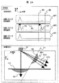
また、原子炉圧力容器の容器貫通部は、沸騰水型原子炉を例にとると、下鏡と呼ばれる直径6〜7メートルの半円形状の構造物が原子炉圧力容器の下部の壁として採用され、その下鏡に直径約20センチメートル程度の穴(制御棒駆動機構用の貫通部)が設けられており、その個数は100〜200個程度である。その穴の方向は、いずれも鉛直方向であるため、図4に示すように、半円形状をした原子炉圧力容器の下鏡と容器貫通部のなす角度は、ひとつひとつの貫通部で異なっている。 In the case of a boiling water reactor, for example, a semicircular structure called a lower mirror with a diameter of 6 to 7 meters is used as the lower wall of the reactor pressure vessel. The lower mirror is provided with holes having a diameter of about 20 centimeters (through portions for the control rod drive mechanism), and the number thereof is about 100 to 200. Since the directions of the holes are all vertical, as shown in FIG. 4, the angle formed by the lower mirror of the semicircular reactor pressure vessel and the vessel penetration portion is different for each penetration portion. .
例えば図4の模式図を例にとって説明すると、中央部では原子炉圧力容器の下鏡と容器貫通部はほぼ直角に交差しているが、外周部では原子炉圧力容器の下鏡と貫通部のなす角度は約45度となっている。 For example, referring to the schematic diagram of FIG. 4, the lower part of the reactor pressure vessel and the vessel penetrating part intersect at a substantially right angle in the central part, but the lower part of the reactor pressure vessel and the penetration part in the outer peripheral part. The angle formed is about 45 degrees.
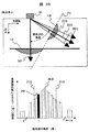
また、あるひとつの容器貫通部においても、その円周方向位置によって原子炉圧力容器と容器貫通部のなす角度が変化する。図5に、外周部の貫通部の例を模式的に示す。図5のA−A断面は、原子炉圧力容器の下鏡の中央部から外周部へ沿う方向での断面を示しており、B−B断面はA−A断面に直交する方向での断面図を示している。山側部では原子炉圧力容器(下鏡)と容器貫通部のなす角度が45度程度であり、反対側の谷側部ではその角度が135度程度である。一方、B−B断面の中腹部では原子炉圧力容器壁と容器貫通部がほぼ直角に交差していることがわかる。 Further, even in a certain vessel penetration portion, the angle formed by the reactor pressure vessel and the vessel penetration portion changes depending on the circumferential position thereof. In FIG. 5, the example of the penetration part of an outer peripheral part is shown typically. The AA cross section in FIG. 5 shows a cross section in the direction from the central portion to the outer peripheral portion of the lower mirror of the reactor pressure vessel, and the BB cross section is a cross sectional view in the direction orthogonal to the AA cross section. Is shown. The angle between the reactor pressure vessel (lower mirror) and the vessel penetration is about 45 degrees at the mountain side, and the angle is about 135 degrees at the valley side on the opposite side. On the other hand, it can be seen that the reactor pressure vessel wall and the vessel penetrating portion intersect at a substantially right angle in the middle of the BB cross section.
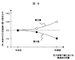
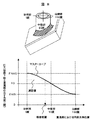
このように、原子炉圧力容器(下鏡)と容器貫通部のなす角度は、2つの要因で決定される。第1に原子炉圧力容器の下鏡における位置関係(中央部から外周部)である。図6に示すように、その下鏡における位置関係により、原子炉圧力容器と容器貫通部のなす角度の最小値と最大値が決定される。第2に容器貫通部における円周方向(谷側部,中腹部,山側部)である。図7に示すように、円周方向の位置関係により、容器貫通部と原子炉圧力容器(下鏡)のなす角度は、上述の最小値と最大値の間の値をとることとなる。 Thus, the angle formed by the reactor pressure vessel (lower mirror) and the vessel penetration is determined by two factors. The first is the positional relationship (from the central part to the outer peripheral part) in the lower mirror of the reactor pressure vessel. As shown in FIG. 6, the minimum value and the maximum value of the angle formed by the reactor pressure vessel and the vessel penetration portion are determined by the positional relationship in the lower mirror. Second, it is the circumferential direction (valley side, middle abdomen, mountain side) in the container penetration part. As shown in FIG. 7, the angle formed between the vessel penetration part and the reactor pressure vessel (lower mirror) takes a value between the above-described minimum value and maximum value, depending on the positional relationship in the circumferential direction.
そこで、前記した項目(2)または(5)のように、原子炉圧力容器の外面に設置した超音波探触子から斜め方向に超音波を送受信することによって、容器貫通部と原子炉圧力容器(下鏡)の傾斜角度(互いのなす角度)を測定できる。これは、超音波が検査対象部位の面に対して90度で送受信する波をほぼ100%に近いエネルギー効率で反射する性質を利用したものであり、傾斜している容器貫通部の面に対してちょうど直行する角度で超音波が送受信された場合の受信信号強度が最も強くなることから、容器貫通部の傾斜角度を評価することができる。 Therefore, as described in item (2) or (5) above, by transmitting and receiving ultrasonic waves obliquely from an ultrasonic probe installed on the outer surface of the reactor pressure vessel, the vessel penetration portion and the reactor pressure vessel The tilt angle of the (lower mirror) (the angle between each other) can be measured. This utilizes the property of reflecting waves transmitted and received at 90 degrees with respect to the surface of the region to be examined with energy efficiency close to 100%, with respect to the inclined surface of the container penetrating portion. Since the received signal intensity when the ultrasonic wave is transmitted / received at an angle that is just perpendicular is the strongest, the inclination angle of the container penetrating portion can be evaluated.
また、前記した項目(3)のように、原子炉圧力容器の傾斜角度、すなわち、原子炉圧力容器の下鏡と容器貫通部のなす角度を測定することで検査位置、すなわち、容器貫通部のうち円周方向のどの位置の部分を検査しているか、を評価することができる。これは、図7の例に示したように、容器貫通部の円周方向位置と傾斜角度が一対一に対応することから、逆に、測定された傾斜角度から、容器貫通部の円周方向位置を推定できるという原理を利用したものである。 Further, as described in item (3) above, by measuring the inclination angle of the reactor pressure vessel, that is, the angle formed between the lower mirror of the reactor pressure vessel and the vessel penetration portion, the inspection position, ie, the vessel penetration portion is measured. It is possible to evaluate which portion in the circumferential direction is being inspected. This is because, as shown in the example of FIG. 7, since the circumferential position and the inclination angle of the container penetrating part correspond one-to-one, conversely, from the measured inclination angle, the circumferential direction of the container penetrating part This is based on the principle that the position can be estimated.
また、測定された傾斜角度、すなわち、原子炉圧力容器の下鏡と容器貫通部のなす角度を超音波検査装置の表示部にて表示するようにしても良い。 Further, the measured tilt angle, that is, the angle formed between the lower mirror of the reactor pressure vessel and the vessel penetration portion may be displayed on the display unit of the ultrasonic inspection apparatus.
さらに、前記した項目(4)から(5)に記載の超音波検査は、下記の項目による手段を持つことができる。
(6)(4)から(5)の内容を有する超音波検査装置において、容器貫通部の傾斜角度を記憶する手段を有することが好ましい。
Furthermore, the ultrasonic inspection described in the items (4) to (5) can have means according to the following items.
(6) In the ultrasonic inspection apparatus having the contents of (4) to (5), it is preferable to have means for storing the inclination angle of the container penetration part.
上述の項目(6)によれば、図8に示すような、容器貫通部の円周方向位置に対する原子炉圧力容器の下鏡の壁面と容器貫通部のなす角度(傾斜角度)のマスターカーブや設計図面を記憶することで、上述の項目(2)または(5)によって測定した傾斜角度から、検査位置、すなわち、貫通部の円周方向位置のどの部分を検査しているか、を特定することができる。 According to the above item (6), as shown in FIG. 8, the master curve of the angle (inclination angle) formed by the wall of the lower mirror of the reactor pressure vessel and the vessel penetration with respect to the circumferential position of the vessel penetration is By storing the design drawing, the inspection position, that is, which part of the circumferential position of the penetrating portion is inspected is specified from the inclination angle measured by the above item (2) or (5). Can do.
以下、本発明による超音波探傷方法及び装置について、図示の実施の形態により詳細に説明する。 Hereinafter, an ultrasonic flaw detection method and apparatus according to the present invention will be described in detail with reference to embodiments shown in the drawings.
図1は本発明の第1の実施形態で、図示のように、この実施対象である検査対象102(破線内)に対して、原子炉圧力容器(以下、単に圧力容器とも言う。)103を介して、超音波を入射する超音波検査装置の超音波探触子101を圧力容器103の外面側に押し付けて探傷する。検査すべき対象の詳細を、図1の拡大図中に溶接部(網掛け部)104として示す。検査対象となる溶接部104は、その表面が曲率を有しており1周にわたってリング状に貫通部を取り囲んだ溶接部となっている。
FIG. 1 shows a first embodiment of the present invention. As shown in the figure, a reactor pressure vessel (hereinafter also simply referred to as a pressure vessel) 103 is inspected with respect to an inspection object 102 (inside the broken line), which is the object of execution. Then, the
実施形態の適用先は、原子炉圧力容器の容器貫通部の溶接部104である。沸騰水型原子炉(BWR)の場合は、制御棒駆動機構(CRD)のスタブチューブ溶接部や炉内計装案内管(ICMハウジング)溶接部等が対象であり、加圧水型原子炉(PWR)の場合は、容器上蓋管台溶接部等が対象として掲げられる。
The application destination of the embodiment is the welded
また、図1では、BWRの場合であるため、原子炉圧力容器の下鏡の外面に超音波探触子を設置する例を示したが、PWRを対象とした場合は、原子炉圧力容器の上蓋の外面に超音波探触子を設置することとなり、図の天地が反転されるが同様に適用することが可能である。 In addition, since FIG. 1 shows the case of BWR, an example in which an ultrasonic probe is installed on the outer surface of the lower mirror of the reactor pressure vessel is shown. However, in the case of targeting PWR, An ultrasonic probe will be installed on the outer surface of the upper lid, and the top and bottom of the figure will be inverted, but it can be applied in the same way.
図22と図24を用いて、検査対象102(図22の2210に相当する。)とその周囲の容器貫通部の関係を説明する。図4に示す沸騰水型原子炉の原子炉圧力容器の下鏡の模式図から、検査対象2210とその周囲の容器貫通部の幾何学的な関係は、図22に示すように、超音波探触子101及び検査対象102の中心を通る直線2201による断面が、周辺の容器貫通部(2202及び2203)の中心を通過する場合と、図24に示すように、超音波探触子101及び検査対象2210の中心を通り直線2401による断面が、周辺の容器貫通部(2402及び2403)の中心を通過しない場合とがある。より一般的な場合は図24に示す後者の場合であるが、実施例1及び2では説明を簡単化するために、図22に示す前者の例について説明する。図24に示す場合は、第3の実施例として相違点を説明する。
The relationship between the inspection object 102 (corresponding to 2210 in FIG. 22) and the surrounding container penetration portion will be described with reference to FIGS. From the schematic diagram of the lower mirror of the reactor pressure vessel of the boiling water reactor shown in FIG. 4, the geometrical relationship between the
検査対象102に超音波を伝達させるため、超音波探触子101が設置される圧力容器103と超音波探触子101の間には、音の伝播効率をよくするために、中間媒質として水やグリセリンといった接触媒質(または、カプラントとも呼ばれる)が塗布または充填されているものとする。
In order to transmit ultrasonic waves to the
超音波探触子101は送受信部106と接続されており、送受信部106は、超音波を送信するためのパルサー電圧を発信し超音波探触子101に送り出す機能や、超音波探触子101で受信された信号を受信する機能を備えている。
The
また、超音波探触子101は走査機構105によって走査面である圧力容器103の外面を1次元的にまたは2次元的に走査される。走査機構105は、制御機構107により走査範囲や走査位置(すなわち、超音波探触子101の位置)を制御されている。このうち、少なくとも走査位置の情報は、送受信部106に送られ、走査位置(超音波探触子の位置)とその位置で受信された信号は組みとなって記録される。
Further, the
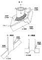
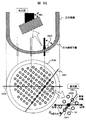
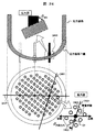
図9に走査機構105の構造の例を示す。超音波探触子101を圧力容器103の外面に接触させるために、走査機構105は、超音波探触子の押し付け機構901を備える。また、その押し付け機構901を所定の検査対象部位まで移動するために、例えば、隣接する制御棒案内管(以下、単に管とも言う。)902をガイドとする回転機構903,上下移動機構904、及び所定の方向に超音波探触子を向けるための探触子回転機構905を備えている。このような走査機構105により、圧力容器103の容器貫通部のうち、検査対象となっている所定の容器貫通部に対応して、超音波探触子101を圧力容器の外面に押し付けて設置することが可能となる。
FIG. 9 shows an example of the structure of the
送受信部106で受信され超音波探触子の位置に関する情報とともに記録された受信信号は、波形または画像として表示部108に表示される。ここでは、超音波探触子としてアレイ探触子を用いたフェーズドアレイ法により探傷した場合について、詳細に説明する。
The received signal received by the transmission /
図10を用いて、アレイ探触子によるフェーズドアレイ法について説明する。アレイ探触子1010とは、小さな圧電素子1001を通常数個から数十個規則的に配列させた探触子のことであり、広く用いられているものとしては、1方向に矩形の素子を配列したリニアアレイ探触子(1020)が知られている。素子の大きさは周波数によって若干変化するが、およそ0.数 ミリから数ミリである。素子1001に対して、送信(発振)及び受信のタイミングを変化させることで様々な超音波ビームを合成する手法がフェーズドアレイ法である。
A phased array method using an array probe will be described with reference to FIG. The array probe 1010 is a probe in which several to tens of small
フェーズドアレイ法を使用する場合、アレイセンサ1010を構成する素子1001に対してあるタイミングのパターン(遅延時間パターン)1002を設定する。各素子から発生する波面1007は合成されて方向1005に伝播する合成波面1006となる。合成面1006は、点1004で互いに強め合うため、点1004は焦点とよばれる。最終的にアレイ探触子1010全体の作る音の分布は、焦点1004に集束する超音波ビーム1003のようになる。フェーズドアレイ法の特徴は、遅延時間パターン1002を変化させることで、焦点1004の深さや、伝播方向1005を自由に且つ高速に電子的に制御することが可能な点である。
When the phased array method is used, a certain timing pattern (delay time pattern) 1002 is set for the
次に、図20を用いて、超音波検査装置の詳細を説明する。超音波検査装置は、アレイ探触子による超音波探触子101,送受信部106,制御機構107,表示部108の構成例について説明する。送受信部106は、遅延時間制御部106B,パルサー106C,レシーバ106D,データ収録部106E,計算機106F,全体を収納する筐体106Aから構成される。
Next, details of the ultrasonic inspection apparatus will be described with reference to FIG. The ultrasonic inspection apparatus will be described with respect to a configuration example of an
フェーズドアレイ法を利用する場合、上述のように、超音波探触子101を構成する各素子に異なったタイミングでパルス信号を与えることで超音波ビームの伝播方向や保焦点位置を電気的に制御することができる。このタイミングのパターン(遅延時間パターン)は計算機106Fにて計算される。このとき、計算に必要なパラメータ、例えば、超音波の入射角度,屈折角度,焦点の有無及び焦点の位置や深さ等は、例えばユーザによって、ポインティングデバイスやキーボードを用いて、計算機106Fに入力される。各素子に与える遅延時間パターンにしたがって、遅延時間制御部106Bから遅延時間に相当する時間だけシフトされたトリガ信号が発生し、アレイ探触子の各素子に対して高電圧パルスを与えるパルサー106Cに送られる。パルサー106Cはアレイ探触子を構成する各素子と接続されているため、アレイ探触子を採用している超音波探触子101は遅延時間パターンによって規定される方向及び焦点位置をともなった超音波ビーム1003を、検査対象である圧力容器103内に発生させる。検査対象内部または表面に反射源が存在する場合には、再び圧力容器103内を反射された超音波が伝播し、超音波探触子101に到達する。
When the phased array method is used, as described above, the propagation direction of the ultrasonic beam and the focal position are electrically controlled by applying pulse signals to the elements constituting the
このとき、超音波探触子101がアレイ探触子であるので、図9を用いて説明したような、走査機構105により、検査対象である圧力容器103の外表面上を移動させ、検査対象の広い範囲について超音波検査を行う。ここで、走査機構105は、走査手段105の移動を制御する走査手段制御部105Aと、探触子位置を検出する移動量検出部105Bから構成される。走査手段制御部105Aとしては、例えばモータ及びモータドライブを用い、移動量検出部としては、エンコーダを用いることができる。
At this time, since the
超音波探触子101に到着した超音波は、超音波探触子の各素子で圧電変換され電気信号へと変換され、各素子に接続されたレシーバ106Dに送られる。ここで、素子からの電気信号は通常非常に微弱であることが多いため、データ収録部106Eでは、アンプにより数ボルト程度に増幅された後、アナログデジタル変換を行い、走査機構105より提供される超音波探触子101の位置と対応して、受信信号がデジタルデータとして記録される。
The ultrasonic waves that have arrived at the
超音波探触子101に対して送受信部106により遅延時間パターン1002の情報が送られることで、超音波探触子101は、例えば扇形111のように伝播方向1005を変化させて超音波を送受信する。圧力容器の内面113及び容器貫通部の内径112と、超音波探触子101の位置関係が図1の[探触子の位置関係]に示すような配置である場合、主に2種類の信号が受信される。第一のエコー109は容器貫通部112の内径112からの反射波であり、第二のエコー110は圧力容器の内面113からの反射波である。これら2種類のエコーから検査対象となる貫通部の検査位置の健全性(欠陥の有無やその寸法等)を評価する。
When the information of the
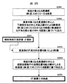
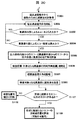
図11に本実施例のフローチャートを示す。超音波検査を実施するにあたって、容器貫通部が複数個ある場合には、検査対象となる容器貫通部を設定する(S1101)。次に、検査対象となる容器貫通部が検査できるまで走査機構105を移動する(S1102)。次に、押し付け機構901で超音波探触子101を圧力容器103の外面に押し付ける(S1103)。
FIG. 11 shows a flowchart of this embodiment. When performing ultrasonic inspection, when there are a plurality of container penetration parts, a container penetration part to be inspected is set (S1101). Next, the
圧力容器外面に押し付けられた超音波探触子101からは、複数の方向に超音波が送信され(S1104A)、反射源が存在する場合にはその角度方向からのエコー(反射波)が受信される。超音波探触子101にアレイ探触子1010を用いたので、扇型111に超音波を送受信し、超音波による画像が表示部108に表示される。
From the
超音波探触子101で受信される主な信号として、圧力容器内面への垂直方向の超音波送受信により得られるエコー110と、貫通部内面によるエコー109がある。これらのエコーのうち、特に容器貫通部内面によるエコー109に注目する。
As main signals received by the
図21Aから図21Cを用いて、容器貫通部内面によるエコーの種類について説明する。検査対象となる容器貫通部を各図の2103A,2103B,2103Cとする。圧力容器と容器貫通部のなす角度θによって、容器貫通部内面によるエコーは3種類に分類することができる。第1は、圧力容器と容器貫通部がほぼ直角をなしている場合(図21A)である。このとき、圧力容器内面と容器貫通部内面の交差する領域に送信した2101Aによって反射エコーを受信することができる。また、検査対象となる容器貫通部2103Aに隣接する容器貫通部2104Aに対しても同様に、圧力容器内面と容器貫通部内面の交差する領域に送信した2102Aによって反射エコーを受信することができる。ここで、ほぼ直角をなしているとみなせる範囲として、2101A及び2102Aがある程度の強さで受信できる範囲とすると、制限はおよそプラスマイナス20度程度となる。
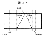
The kind of echo by the container penetration part inner surface is demonstrated using FIG. 21A to FIG. 21C. Let the container penetration part used as a test object be 2103A, 2103B, and 2103C of each figure. Depending on the angle θ formed between the pressure vessel and the container penetrating portion, the echoes from the inner surface of the container penetrating portion can be classified into three types. The first is a case where the pressure vessel and the vessel penetration portion are substantially perpendicular (FIG. 21A). At this time, the reflected echo can be received by 2101A transmitted to the region where the inner surface of the pressure vessel and the inner surface of the container penetrating portion intersect. Similarly, with respect to the
第2は、圧力容器と容器貫通部がある程度(例えば20度以上)の角度をなしており、圧力容器内面と容器貫通部内面が鋭角に交差する領域に対して、超音波検査装置の超音波探触子2105(超音波探触子101と同じである。)から超音波2101Bが送信される場合である(図21B)。この場合は、図21Aの例と同様に、圧力容器内面と容器貫通部内面が鋭角に交差する領域からの反射波を受信することが期待されるが、受信時の強度が十分でない可能性があるため検査位置特定のために利用することは困難と考えられる。一方で、検査対象となる容器貫通部2103Bに隣接する容器貫通部2104Bに対して直接送信された超音波2102Bによっても、反射エコーを受信することができるが、こちらは反射源に対して直射される超音波であり強度も十分と予想されるので、検査位置特定のために利用することができる。
Second, the ultrasonic wave of the ultrasonic inspection apparatus is applied to a region where the pressure vessel and the container penetration part form an angle (for example, 20 degrees or more) and the pressure vessel inner surface and the container penetration part inner surface intersect at an acute angle. This is a case where the ultrasonic wave 2101B is transmitted from the probe 2105 (the same as the ultrasonic probe 101) (FIG. 21B). In this case, as in the example of FIG. 21A, it is expected to receive a reflected wave from a region where the inner surface of the pressure vessel and the inner surface of the container penetrating portion intersect at an acute angle, but the intensity at the time of reception may not be sufficient. Therefore, it is considered difficult to use for specifying the inspection position. On the other hand, the reflected echo can also be received by the
第3は、圧力容器と容器貫通部がある程度(例えば20度以上)の角度をなしており、圧力容器内面と容器貫通部内面が鈍角に交差する場合である(図21C)。この場合は、圧力容器内面と容器貫通部内面が鈍角に交差する領域からの反射波を得ることが幾何学的に困難であるため、検査対象となる容器貫通部2103Cの内面に直接送信された超音波2101Cによって反射エコーを受信することができる。この信号も反射源に直射する超音波であるため受信感度が十分高いことが予想されるので探傷位置(検査位置と同じである。)特定に利用することができる。また、検査対象となる容器貫通部2103Cに隣接する容器貫通部2104Cに対して、圧力容器内面と容器貫通部内面の交差する領域に送信した2102Cによって反射エコーを受信することが期待されるが、受信時の強度が十分でない可能性があるため検査位置特定のために利用することは困難と考えられる。
The third is a case where the pressure vessel and the container penetration part form an angle of a certain degree (for example, 20 degrees or more), and the pressure vessel inner surface and the container penetration part inner surface intersect at an obtuse angle (FIG. 21C). In this case, since it is geometrically difficult to obtain a reflected wave from a region where the inner surface of the pressure vessel and the inner surface of the container penetrating portion intersect at an obtuse angle, it is directly transmitted to the inner surface of the
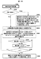
この2種類のエコー(図21Aから図21Cにおける2101A〜C及び2102A〜C)のうち、いずれかまたは両方を利用して、次のステップ(S1105)で探傷位置を特定する評価を行う。しかしながらその前の段階として、超音波探触子101からの超音波の伝搬方向が、図22の断面2201内に存在するかを確認する必要がある。すなわち、超音波探触子101を走査機構105の探触子回転機構905によって、超音波探触子101を回転させ、上述の2種類のエコーのうちの少なくともいずれかの信号が最大位置となるように、探触子の回転位置を調整する(S1104B)。
Of these two types of echoes (2101A to C and 2102A to 2102A to C in FIGS. 21A to 21C), an evaluation for specifying the flaw detection position is performed in the next step (S1105) using either or both. However, as a previous step, it is necessary to confirm whether the ultrasonic wave propagation direction from the
容器貫通部内面による2種類のエコー(図21Aから図21Cにおける2101A〜C及び2102A〜C)の少なくともいずれかが最大値を与える場合に、次のステップへと進み(S1104C)、これら2種類のエコーを利用して圧力容器と容器貫通部のなす角度(傾斜角度)を評価し(S1105)、測定された傾斜角度から、検査位置(対象となる貫通部の円周方向位置)を特定する(S1106)。なお、S1105及びS1106の詳細は後述することとする。 When at least one of two types of echoes (2101A to C and 2102A to 2102A to C in FIGS. 21A to 21C) gives the maximum value, the process proceeds to the next step (S1104C). The angle (inclination angle) formed between the pressure vessel and the container penetrating portion is evaluated using echo (S1105), and the inspection position (circumferential position of the target penetrating portion) is specified from the measured inclination angle ( S1106). Details of S1105 and S1106 will be described later.
複数の方向に超音波を送受信した結果、上述の形状に起因するエコー以外にエコーが得られなかった場合は、特定された検査位置を健全と判断する。また、何か他にエコーが存在した場合は、欠陥の可能性があると判断する(S1107)。欠陥の可能性を詳細に検討するために、形状に起因しないエコーに関して、反射波を受信した時間や角度から、反射源の位置や寸法を評価する(S1109)。健全か否かの最終的な判断は、いくつかの手法(例えば、周波数や角度,センサの配置位置)による総合判断により決定されることが一般的であるので、図11に示したフローチャートでは、欠陥の可能性と、その反射源の位置及び寸法を評価する点で終了するものとする。なお、S1109の詳細は後述することとする。 As a result of transmitting and receiving ultrasonic waves in a plurality of directions, if no echo is obtained other than the echo due to the above-described shape, the specified inspection position is determined to be healthy. If any other echo is present, it is determined that there is a possibility of a defect (S1107). In order to examine the possibility of the defect in detail, the position and size of the reflection source are evaluated from the time and angle at which the reflected wave is received with respect to the echo not caused by the shape (S1109). Since the final determination of whether or not the sound is normal is generally determined by a comprehensive determination by several methods (for example, frequency, angle, and sensor arrangement position), in the flowchart shown in FIG. We shall end with the point of evaluating the possibility of a defect and the position and size of its reflection source. Details of S1109 will be described later.
ここで、図11に示したステップ(S1105及びS1106)について、図2A及び図12を用いてその詳細を説明する。図2Aは、圧力容器及び容器貫通部の形状に起因するエコーの受信波形及び画像の例を示す。ただし、図2Aに示す容器貫通部内面によるエコー109は、図21Bの2102B、または、図21Cの2101Cに相当する、容器貫通部内径に直射するエコーの例である。
Details of the steps (S1105 and S1106) shown in FIG. 11 will be described with reference to FIGS. 2A and 12. FIG. FIG. 2A shows an example of a received waveform and an image of an echo caused by the shape of the pressure vessel and the vessel penetration portion. However, the
断面表示の図形は、走査軸方向(探傷面に平行な方向)と深さ方向(探傷面に垂直な方向)の2つの軸によって検査対象の断面図を描画したものである。複数の角度方向に送受信した超音波をその信号を送受信した方向に描画して表示している。そのため、図1に示すように、圧力容器の内面113とそこからのエコー110、及び、容器貫通部の内面
112とそこからのエコー109は、位置関係を崩さずに表示される。ただし、ここでひとつ注意すべき点がある。超音波はある1方向に送受信したとしても、指向角と呼ばれるある広がりを持ってその方向に伝播している。そのため、形状からのエコー(109及び110)は超音波の送受信方向に広がりをもって表示される。
The cross-sectional display graphic is a drawing of a cross-sectional view to be inspected by two axes, a scanning axis direction (direction parallel to the flaw detection surface) and a depth direction (direction perpendicular to the flaw detection surface). The ultrasonic waves transmitted and received in a plurality of angular directions are drawn and displayed in the direction in which the signals are transmitted and received. Therefore, as shown in FIG. 1, the
実際の形状と正対している超音波の送受信方向を決めるための方法を図2Aの[受信波形]を用いて説明する。受信波形207Aから207Cは、送受信方向201AからCでの受信波形を示している。時間的に最初に受信される信号203は検査対象の表面を意味するエコーである。時間ゲート205及び206の間に存在するエコー204が形状に起因するエコーとなる。このとき、伝播時間202と検査対象となる材料の音速から伝播距離を求めることができる。形状に起因するエコー204の強度に注目すると、送受信方向が201Aから201Cに変化するにつれて、その強度は、201Aと201Cの中間位置である201Bにて極大値をとることがわかる。この極大値をとる方向が、形状に正対して超音波が送受信されている方向と判断して、送受信方向201Bに垂直な方向201を容器貫通部の内径の角度と評価する。
A method for determining the transmission / reception direction of the ultrasonic wave facing the actual shape will be described with reference to [Received waveform] in FIG. 2A.
同様に、超音波の送受信方向202に対しても、送受信角度を、図2A中の送受信方向202を中心に±の左右両側に変化させて、エコー強度が極大となる送受信方向を圧力容器内面に正対する方向と判断し、その方向に直交する方向110を圧力容器内面の傾斜角度と評価する。通常、圧力容器内面と探触子の走査面は平行であるため、圧力容器内面の傾斜角度方向110は水平方向となるので、容器貫通部内面の傾斜角度は圧力容器内面の傾斜角度方向110ではなく探傷面を基準とするものとする。
Similarly, with respect to the ultrasonic transmission /
なお、圧力容器の板厚や探傷面との位置関係(水平)の情報を用いて、超音波探触子
101及び表示部108の校正のために、圧力容器内面からのエコー(110A)及びその伝搬時間(110B)を用いてよい。
In order to calibrate the
図12に、管内面への直射超音波(図21Bの2102B、または、図21Cの2101C)を用いた場合の位置評価に係るフローチャートを示す。上述のように、圧力容器と容器貫通部のなす角度(傾斜角度)を超音波により測定する(S1105)。次に、検査の最初のステップ(S1101)で指定されている検査対象となる容器貫通部の位置から、傾斜角度の最小値(または最大値)を求める(S1201)。この角度は、例えば、設計図面
(2次元断面)またはCADデータ(2次元または3次元)を求める事が出来る。最後に、測定した傾斜角度(θ傾斜)と傾斜角度の最小値(θMIN) を数1に代入して、検査位置すなわち容器貫通部の円周方向の位置(円周方向の角度として表すと、数1のθ円周方向)を求める。
FIG. 12 shows a flowchart relating to position evaluation in the case of using direct ultrasonic waves (2102B in FIG. 21B or 2101C in FIG. 21C) on the inner surface of the tube. As described above, the angle (inclination angle) formed by the pressure vessel and the container penetration portion is measured by ultrasonic waves (S1105). Next, the minimum value (or maximum value) of the inclination angle is obtained from the position of the container penetration part to be inspected specified in the first step (S1101) of inspection (S1201). For this angle, for example, a design drawing (two-dimensional section) or CAD data (two-dimensional or three-dimensional) can be obtained. Finally, the measured inclination angle (θ inclination ) and the minimum value (θ MIN ) of the inclination angle are substituted into

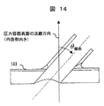
なお、数1の中で使用した、θ円周の定義を図13に示す。θ円周方向は、谷側を0度とし山側に向かって圧力容器外面側から見て時計回りにθが大きくなる。また、θ傾斜
(及びθMINも同様)の定義を図14に示す。θ傾斜は、圧力容器の法線方向(内面側向き)を0度とし、容器貫通部の軸方向とのなす角として定義する。
The definition of the θ circumference used in
The definition of (and θ MIN is the same) is shown in FIG. The θ inclination is defined as an angle between the normal direction (inner surface side direction) of the pressure vessel and the axial direction of the vessel penetration portion.
図12の処理(S1201とS1202)は、手計算にて実施することも可能であるが、実際の検査の場合、検査対象となる機器の図面及び寸法が予め数値化されている場合が想定される。このように、検査対象の図面に記された形状が数値化されている場合には、図25,図26,図27に示すステップにしたがって、コンピュータである計算機106Fを利用して自動的に計算処理を行うことができる。
The processing in FIG. 12 (S1201 and S1202) can be performed manually, but in the case of an actual inspection, it is assumed that the drawing and dimensions of the device to be inspected are digitized in advance. The Thus, when the shape described in the drawing to be inspected is digitized, it is automatically calculated using the
まず、検査対象となる容器貫通部(例えば、図22に示す2210)を指定する
(S2501)。次に、検査対象となる貫通部の中心と下鏡全体の中心を結ぶ線分による断面図(例として、図22に示す2220)から、圧力容器と貫通部のなす角の最小値
θMIN を図面に基づいて出力する(S2502)。具体的には、例えば、図面から手動または自動的に角度を算出すればよい。次に、傾斜角度の測定値(S2601)を用いて、貫通部の円周方向位置(θ円周方向)を数1により計算する。円周方向位置が決まることで、検査対象となる貫通部の中心と超音波探触子101の送信位置を結ぶ線分による断面図(例として、図22に示す2201)を、検査対象全体図面(例として図22の2250)及びその図面による寸法に基づいて、出力する(S2504)。最後に、UT結果と合成(図27を用いて詳細を後述)して表示する(S2701)。
First, a container penetration part (for example, 2210 shown in FIG. 22) to be inspected is designated (S2501). Next, from the cross-sectional view (for example, 2220 shown in FIG. 22) connecting the center of the penetration part to be inspected and the center of the entire lower mirror, the minimum value θ MIN of the angle formed by the pressure vessel and the penetration part is obtained. Output based on the drawing (S2502). Specifically, for example, the angle may be calculated manually or automatically from the drawing. Next, using the measured value of the tilt angle (S2601), the circumferential position (θ circumferential direction ) of the penetrating portion is calculated by
次に、図26を用いて傾斜角度の測定(S2601)について説明する。この処理は手動または計算機による自動の処理を選択することができる(S2602)。 Next, the measurement of the tilt angle (S2601) will be described with reference to FIG. This process can be selected manually or automatically by a computer (S2602).
手動を選択した場合の処理(S2603)では、超音波の入射角度に対応する指示手段(図2Bに示す角度カーソル201B)を手動で変化させながら、貫通部内径による信号の強度の最大値を調べて、強度のピークを与える超音波入射角度を、90度から減算して「θ入射角度」とする。 In the processing when manual is selected (S2603), the maximum value of the signal intensity due to the inner diameter of the penetrating portion is checked while manually changing the instruction means (angle cursor 201B shown in FIG. 2B) corresponding to the incident angle of the ultrasonic wave. Then, the ultrasonic incident angle that gives the intensity peak is subtracted from 90 degrees to obtain the “θ incident angle”.
自動を選択した場合は、自動処理のため最大値を0で初期化(S2604)した後、超音波の入射角度をN通り(通常、Nは数十から百程度)、1番目からN番目まで変化させながら、貫通部内径によるエコー、すなわち、時間ゲート205及び206の間に存在するエコー204の強度を測定し記録する(S2605)。それぞれの角度に対する強度と最大値と比較することで最大値を検索し(S2606及びS2607)、最終的に、強度の最大値を与える入射角度を90度から減算して「θ傾斜角度」とする(S2609)。
If automatic is selected, the maximum value is initialized to 0 for automatic processing (S2604), and then the ultrasonic incident angles are N (usually N is about several tens to hundreds), from the first to the Nth While changing, the echo due to the inner diameter of the penetrating portion, that is, the intensity of the
次に、図27を用いて傾斜角度の測定(S2701)について説明する。本処理の最終目的は、超音波探傷結果における超音波探触子101の走査面と、検査対象の断面図(図22の線分2201による断面図)の位置を一致させて表示することにある。
Next, measurement of the tilt angle (S2701) will be described with reference to FIG. The final purpose of this process is to display the scanning surface of the
まず、探傷結果における走査面(図15Aに示す1510)と検査対象の断面図の表面位置(図15Aに示す1520)を一致させる(S2702)。次に、検査対象となる容器貫通部内径の傾斜角度(θ傾斜角度)において、超音波探触子101の中心と容器貫通部内径(図15Aに示す1530)までの測定値から、貫通部内径端から超音波探触子までの距離を数3により計算し、断面図上の送信位置(図15Aに示す1525)を求める(S2703)。数式における各記号文字は図31に示す内容を表す。探傷結果上の送信点位置(図15Aに示す1515)と、先程計算により求めた断面図上の送信位置(図
15に示す1525)を一致させる。
First, the scanning surface (1510 shown in FIG. 15A) in the flaw detection result and the surface position (1520 shown in FIG. 15A) of the cross-sectional view to be inspected are matched (S2702). Next, in the inclination angle (θ inclination angle) of the inner diameter of the container penetration portion to be inspected, from the measured values up to the center of the
![]()
![]()
これらの処理により、上下左右方向ともに両図面の位置合わせが終わり、図の重ね合わせ方法が一意に定まったので、手動での微調整が必要かを合成画像にて確認し(S2704)、必要に応じて微調整を実施した後(S2705)、探傷結果と断面図を重ね合わせて合成図(例として、図15(C))を表示する。 With these processes, the alignment of both drawings in both the top, bottom, left, and right directions has been completed, and the method of overlaying the drawings has been uniquely determined, so it is confirmed in the composite image whether manual fine adjustment is necessary (S2704). After performing fine adjustment accordingly (S2705), the flaw detection result and the cross-sectional view are superimposed and a composite diagram (for example, FIG. 15C) is displayed.
上述の説明は、検査対象となる容器貫通部2103A〜Cとそれに隣接する貫通部
2104A〜Cの関係が、図21Cに相当する場合、すなわち、検査対象となる容器貫通部と容器貫通部の傾斜を測定するための超音波の反射面を提供した容器貫通部が一致している場合である。
In the above description, the relationship between the
他の場合の説明として、検査対象となる容器貫通部と容器貫通部の傾斜を測定するための容器貫通部が必ずしも一致していない場合で、かつ、隣接する容器貫通部内面からの直射エコーを利用する場合について説明する。この場合の特徴は、超音波探触子から見て、検査対象となる容器貫通部と圧力容器が鈍角に交差しており、検査対象となる容器貫通部の内面からの直射エコーの受信が困難な場合に相当する。 As an explanation of other cases, the case where the container penetration part to be inspected and the container penetration part for measuring the inclination of the container penetration part do not necessarily match, and the direct echo from the inner surface of the adjacent container penetration part is used. The case of using will be described. The feature in this case is that it is difficult to receive a direct echo from the inner surface of the container penetration part to be inspected because the container penetration part to be inspected and the pressure vessel intersect at an obtuse angle as seen from the ultrasonic probe. It corresponds to a case.
図15Bに、検査対象となる容器貫通部に隣接する容器貫通部の位置関係の例を示す。図15Aと同様に、超音波探触子101の中心と、検査対象である容器貫通部2210と隣接する容器貫通部2203の内径までの測定値から、容器貫通部内径端から超音波探触子までの距離(図15Bに示すr)を数3により計算する。その後、検査対象の図面等で指示されている、検査対象となる容器貫通部2210とそれに隣接する容器貫通部2203の内径端から内径端までの距離(図15Bに示すR)から、先程算出した隣接する容器貫通部内径端から超音波探触子までの距離(r)を減算し、検査対象となる容器貫通部2210の内径端から超音波探触子101までの距離1530Bを計算し、超音波の送信位置とする。この送信位置を用いて、図27に示すフローチャートに基づいて、探傷画面と断面図を重ね合わせる。
FIG. 15B shows an example of the positional relationship between the container penetration parts adjacent to the container penetration part to be inspected. Similarly to FIG. 15A, from the measured value up to the center of the
また、図15Cには、検査対象となる容器貫通部と容器貫通部の傾斜を測定するための容器貫通部が必ずしも一致していない場合で、かつ、検査対象及び隣接する容器貫通部と、圧力容器の交差する領域からのエコーを利用する場合について説明する。この場合の特徴は、容器貫通部がほぼ垂直に圧力容器と交差している場合である。 Further, FIG. 15C shows a case where the container penetration part to be inspected and the container penetration part for measuring the inclination of the container penetration part do not necessarily coincide with each other, and the inspection object and the adjacent container penetration part, A case of using echoes from regions where containers intersect will be described. The feature in this case is a case where the container penetrating portion intersects the pressure vessel substantially vertically.
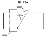
圧力容器内面と容器貫通部内面の交差する領域からの超音波(図21Aの2101A及び2102A)を利用する場合には、図15Cに示すように、検査対象の貫通部2303Aまたは隣接する貫通部2304Aと圧力容器の交差する領域からのエコーの伝搬距離(WまたはW′)を測定し、数4または数5を用いて、容器貫通部内径から超音波探触子101の送信位置までの距離を測定し、探傷結果と断面図を合成するものである。
When using ultrasonic waves (2101A and 2102A in FIG. 21A) from the region where the inner surface of the pressure vessel intersects with the inner surface of the container penetrating portion, as shown in FIG. 15C, the penetrating
![]()
![]()
![]()
![]()
数4を利用する場合は、算出された距離をそのまま用いればよいが、隣接する容器貫通部を利用する場合、すなわち、数5を利用する場合には、図15Bを用いて説明した上述の場合と同様に、両容器貫通部の内径端の距離(図15Cに示すR)から、数5による計算結果を減算することで所望の値、すわなち、検査対象となる容器貫通部内径と探触子の送信位置までの距離を得ることができる。
When using Equation 4, the calculated distance may be used as it is, but when using the adjacent container penetration portion, that is, when using
このように、検査対象となる容器貫通部が特定されている状況においては、超音波によって測定された圧力容器との容器貫通部の傾斜角度から、容器貫通部の円周方向での検査位置(円周方向位置)を特定することができ、通常厚板材のため従来どの部分を検査しているのかを判断することが難しかった圧力容器内側の溶接部に対して、どの部分を検査しているかという検査位置を特定することができる。 Thus, in the situation where the container penetration part to be inspected is specified, the inspection position in the circumferential direction of the container penetration part (from the inclination angle of the container penetration part with the pressure vessel measured by ultrasonic waves ( (Circumferential position) can be specified, and it is usually difficult to determine which part is being inspected because of the thick plate material, which part is being inspected against the weld inside the pressure vessel The inspection position can be specified.
本実施例の説明の最後に、図11に示したステップ(S1109)について、図15A及び図19を用いてその詳細を説明する。図19は、圧力容器の外面から超音波検査した場合の探傷画像例であり、図19はS1109の詳細を表したフローチャートである。図19に示すように、フローは、探傷で得られた画像の表示(S1901)と、断面図との重ね合わせ(S1902)、反射源位置及び寸法の測定(S1903)の3つのステップから構成される。以下、探傷画像の例を使って説明する。 At the end of the description of the present embodiment, the details of step (S1109) shown in FIG. 11 will be described with reference to FIGS. 15A and 19. FIG. 19 is an example of a flaw detection image when an ultrasonic inspection is performed from the outer surface of the pressure vessel, and FIG. 19 is a flowchart showing details of S1109. As shown in FIG. 19, the flow is composed of three steps: display of an image obtained by flaw detection (S1901), overlaying with a cross-sectional view (S1902), and measurement of a reflection source position and dimensions (S1903). The Hereinafter, an example of a flaw detection image will be described.
図15A(A)に探傷画像の模式図を示す。これまで説明したように、エコー109は、貫通部の内径からのエコーである。エコー109を最も強くとらえることができる送受信の方向(角度)210Bに直交する方向210として、圧力容器と容器貫通部のなす角度(傾斜角度)が求められる。図15A(B)に探傷画像の例を示す。図15A(B)において観察される3つのエコー(1501〜1503)のうち、エコー109に該当するものはエコー1501である。このエコー1501を最も強くとらえる送受信角度1507に直交する方向として、傾斜角度を求めることができる。この傾斜角度と設計時の図面から、検査対象部の断面画像1504を作成し、探傷画像に重ねて表示する。
FIG. 15A shows a schematic diagram of a flaw detection image. As described above, the
このように、少なくとも形状に起因するエコーを含んだ探傷結果を検査対象の図面(断面画像)と合成し比較することで、例えば、エコー1503は、断面図の圧力容器の内面側から溶接部表面の輪郭線とほぼ一致することから、溶接表面(曲面部)近傍の形状エコーであることがわかる。一方、エコー1502は、溶接部の中央部に存在することが分かるので、この反射源が欠陥あるいはその先端である可能性が高いことが分かる。また、この探傷画像と設計図面の重ね合わせによって、反射源(エコー1503に相当)の溶接表面からの深さ1506や、圧力容器外面(探傷面)からの深さ1505を測定することができ、反射源が欠陥であった場合に、欠陥の進展を考慮した安全性の評価に利用することができる。本例は、図15Aを用いて説明したが、図15B及び図15Cの場合に関しても、同様の比較検討を実施することができる。
Thus, by combining and comparing the flaw detection result including at least the echo due to the shape with the drawing to be inspected (cross-sectional image), for example, the
以上、本発明の第1の実施例においては、圧力容器外面に超音波探触子を設置し、圧力容器と貫通部のなす角度(傾斜角度)を測定することで、超音波検査の検査位置を特定し、その結果、設計図面と比較することによって、反射源の位置や寸法を測定する方法及び装置を提供することができる。 As described above, in the first embodiment of the present invention, the ultrasonic probe is installed on the outer surface of the pressure vessel, and the angle (inclination angle) formed by the pressure vessel and the penetrating portion is measured, so that the inspection position of the ultrasonic inspection is obtained. As a result, it is possible to provide a method and an apparatus for measuring the position and size of the reflection source by comparing with the design drawing.
図3は本発明の第2の実施形態で、図示のように、この実施対象である検査対象102(破線内)に対して、圧力容器103を介して、超音波を入射する超音波探触子101を圧力容器103の外面側に押し付けて探傷する点は第1の実施形態と同じである。
FIG. 3 shows a second embodiment of the present invention. As shown in the figure, an ultrasonic probe that injects an ultrasonic wave through the
第2の実施形態が第1の実施形態と異なる点は、超音波検査装置に、図面データベース301,記憶部302,演算部303,出力部304、が備わっている点である。記憶部302には、図8に示すような、貫通部における円周方向と、圧力容器と貫通部のなす角度(傾斜角度)に関する関係(マスターカーブ)が記憶されている。マスターカーブ作成にあたって、図面データベース301に記憶されている情報を用いてもよい。
The second embodiment is different from the first embodiment in that the ultrasonic inspection apparatus includes a
計算機として採用したコンピュータによる演算部303において、超音波により測定された傾斜角度とマスターカーブを比較演算することによって、検査位置を特定する。特定した検査位置は、出力部304に角度として、または、図面データベース301に記憶されている図面情報を利用して図面として表示してもよい。このような比較演算の機能を先の実施例1の送受信部の計算機106Fに担わせても良い。
In the
なお、記憶部302に記憶されているマスターカーブは、容器貫通部における円周方向と、圧力容器と容器貫通部のなす角度(傾斜角度)が理論的に1対1に対応した関係になっているので、図8に示すように、測定値(Y軸)とマスターカーブの交点からX軸に垂線を下ろすことによって検査位置(円周方向の角度)を求めることができる。
In addition, the master curve memorize | stored in the memory |
なお、本実施例において、検査位置の特定に関してマスターカーブを利用する点以外は、第1の実施形態に同じである。 In this embodiment, the second embodiment is the same as the first embodiment except that a master curve is used for specifying the inspection position.
図16を用いて、本発明の第3の実施形態を説明する。第3の実施例が第1または第2の実施例と異なる点は、第3の実施例では、図24に示すように、超音波探触子101及び検査対象2410(検査対象102と同じ。)の中心を通り直線2401による断面が、周辺の容器貫通部(2402及び2403)の中心を通過しないという点である。このような状況は、例えば、検査実施対象が、図16に示したように、容器貫通部1601を中心として、貫通部1601を取り囲む円周(1610)に沿って超音波探触子101を走査させながら溶接部を検査する場合に、一般的に発生する。
A third embodiment of the present invention will be described with reference to FIG. The third embodiment is different from the first or second embodiment in that the third embodiment is the same as the
超音波検査装置の探触子101によって検査対象1601のどの部分を検査しているかを明確にすることで検査対象部位を特定する必要がある。すなわち、検査対象部位を特定するには、検査対象1601における容器貫通部の円周方向位置及び、容器貫通部から探触子101の距離が明確になれば、検査対象の位置を特定することができる。
It is necessary to specify the inspection target part by clarifying which part of the
特に、検査対象となる機器の図面が存在するなどの理由で、検査対象全体(図24)のうちから検査対象の容器貫通部(図24においては2410、図16においては1601)が特定できている場合には、検査対象となる容器貫通部1601に対する超音波探触子
101の位置関係を特定するには、検査対象となる容器貫通部1601以外のいずれかの容器貫通部(本実施例の場合は1602)に対する超音波探触子101の位置関係が特定され、探触子101の位置が特定されればよい。実施例1には、検査対象以外の容器貫通部を利用する例のうち、特別な場合として、検査対象となる貫通部とそれ以外の隣接する容器貫通部が、超音波探触子101を含んで1直線上に並ぶ場合(図21A〜C及び図
22参照)について説明した。
In particular, the container penetration part (2410 in FIG. 24 and 1601 in FIG. 16) to be inspected can be specified from the entire inspection object (FIG. 24) because the drawing of the equipment to be inspected exists. In order to identify the positional relationship of the
第3の実施形態では、検査対象の容器貫通部1601の検査位置を評価するにあたって、容器貫通部1601に隣接する別の容器貫通部1602の傾斜角度を利用するために超音波探触子101の超音波送信方向を変化させることが特徴である。
In the third embodiment, in evaluating the inspection position of the
隣接する容器貫通部1602に対して、圧力容器と容器貫通部1602のなす角(傾斜角度)を求める手段,方法,手順は、第1及び第2の実施形態と同様である。
The means, method, and procedure for obtaining the angle (inclination angle) between the pressure vessel and the
なお、図16に示す容器貫通部1601は、容器貫通部1602と比較して貫通部の径の細い場合について図示しているが、容器貫通部1601と隣接する容器貫通部、すなわち、傾斜角度を測定する対象となる容器貫通部1602の径が同じ場合でも以降の説明は同様に成立する。
The
本発明の実施例3の作業フローを図30に示す。なお、初期のフローは図11に示す内容と同様であるので、途中のステップからのみ記載してある。 FIG. 30 shows a work flow of the third embodiment of the present invention. Since the initial flow is the same as that shown in FIG. 11, only the steps in the middle are described.
超音波検査を実施するにあたって、検査対象となる容器貫通部が複数個ある場合には、検査対象となる容器貫通部を設定する(S1101)。次に、検査対象となる容器貫通部1601を検査するにあたって、検査対象となる容器貫通部近傍まで走査機構105を移動する(S1102)。次に、押し付け機構901で超音波探触子101を圧力容器103の外面に押し付ける(S1103)。
When performing an ultrasonic inspection, when there are a plurality of container penetration parts to be inspected, the container penetration part to be inspected is set (S1101). Next, when inspecting the
圧力容器外面に押し付けられた超音波探触子101からは、複数の方向に超音波が送信され(S3001)、反射源が存在する場合にはその角度方向からのエコー(反射波)が受信される。
From the
本実施例では、図16〜図18に示すように、検査対象となる容器貫通部と、検査位置(すなわち、探触子の位置と方向)を特定するための容器貫通部、及び超音波探触子101の3点が同一直線上にないために、検査対象部の探傷を実施する前に、検査位置を特定する必要がある。
In this embodiment, as shown in FIGS. 16 to 18, a container penetration part to be inspected, a container penetration part for specifying the inspection position (that is, the position and direction of the probe), and an ultrasonic probe Since the three points of the
検査位置を特定するために、図17及び図18に示すように、超音波探触子101からの超音波ビームの送信方向を回転させ、検査位置を特定するための容器貫通部1602に向けて超音波の送信方向を変化させる必要がある(S3002)。このとき、超音波ビームの送信方向の回転手段として、例えば、図28に示すような機械的な方法(図9の905に示した機械的な回転機構を利用)を用いてもよいし、図29に示すような、超音波探触子を2次元のアレイ状にしたマトリクス型のアレイ探触子により電子的に送信方向を回転させてもよい。
In order to specify the inspection position, as shown in FIGS. 17 and 18, the transmission direction of the ultrasonic beam from the
なお、機械的な方法の場合、超音波の送信方向を変化させるためには、回転機構905を用いて探触子2801そのものを物理的に回転することで、所望する送信方向2810を得ることができる。また、電子的な方法の場合は、マトリクス状のアレイ探触子2901を構成する各素子と送信方向の基準となる焦点2910の座標から、両点の距離を伝搬する時間を計算し、マトリクス状アレイ探触子2901の各素子から発せられた超音波が同時に焦点2910に到達するように、各素子に対して時間的な遅延を与えることで、送信方向を制御することができる。通常、電子的な送信方向の制御機能は、図20に示すシステム構成例の送受信部で実現することが可能である。
In the case of the mechanical method, in order to change the transmission direction of the ultrasonic wave, a desired
このように超音波送信方向を回転させることで、図17に示すように、本来であれば検査対象となる容器貫通部1601と超音波探触子101の送信位置を通過する線分1701による断面図1710が、超音波探触子から見て、圧力容器と貫通部のなす角度が鈍角となり貫通部内径面からの直射エコーの受信が困難な場合であっても、図16のように、超音波の送信方向を「θ回転」(1620)だけ回転させることで、図18に示すように、隣接する貫通部の中心と超音波探触子101の送信位置を通過する線分1801による断面図(1810)が図15Aで示す例と同様の断面を得ることができ、実施例1と同様の方法により検査位置を特定することができる。
By rotating the ultrasonic transmission direction in this way, as shown in FIG. 17, a cross section of a
実施例1においては、検査対象となる貫通部と検査位置特定のための容器貫通部が同一断面上に存在したが、本実施例では、これらの容器貫通部は超音波探触子と同一面内に同時には存在できないため、検査位置を特定するために用いたエコー(図21Aから図21Cにおける2101A〜C及び2102A〜C)は、図23に示すように、それぞれ2301A,2302B,2301Bとなる。 In the first embodiment, the penetrating portion to be inspected and the container penetrating portion for specifying the inspection position exist on the same cross section. In this embodiment, these container penetrating portions are on the same plane as the ultrasonic probe. The echoes (2101A to C and 2102A to 2102A to C in FIGS. 21A to 21C) used for specifying the examination position become 2301A, 2302B, and 2301B, respectively, as shown in FIG. .
これらの信号のいずれかを利用して、次のステップ(S3005)で探傷位置を特定する評価を行う。しかしながらその前の段階として、超音波探触子101からの超音波の伝搬方向が、図16の断面1801内、すなわち、超音波探触子101の入射点と、検査位置を特定するための隣接する貫通部2403の中心を通過する線分による断面に存在するかを確認する必要がある。
Using any of these signals, evaluation for specifying the flaw detection position is performed in the next step (S3005). However, as a previous step, the propagation direction of the ultrasonic wave from the
超音波探触子101を走査機構105の探触子回転機構905または2次元的に配列されたアレイ探触子2901よって、超音波探触子101の超音波送信方向を回転させ、上述のエコー信号が受信できているか(S3003)、また、受信できているようであれば最大強度位置となっているか(S3004)を確認しながら、超音波の送信方向を回転により調整する。
The
容器貫通部内面によるエコー(図23の2301A,2302B,2301C)のいずれかが最大値を与える場合に、次のステップへと進み(S3005)、これらのエコーを利用して圧力容器と容器貫通部のなす角度(傾斜角度)を評価し(S1105)、測定された傾斜角度から、検査位置(対象となる貫通部の円周方向位置)を特定する(S3006)。なお、これらのS3005及びS3006の詳細は実施例1と同様である。 If any of the echoes (2301A, 2302B, 2301C in FIG. 23) by the inner surface of the container penetrating portion gives the maximum value, the process proceeds to the next step (S3005), and using these echoes, the pressure vessel and the container penetrating portion are used. Are evaluated (inclination angle) (S1105), and the inspection position (circumferential position of the target penetrating portion) is specified from the measured inclination angle (S3006). The details of S3005 and S3006 are the same as those in the first embodiment.
超音波探触子101の位置を特定した後に、上述の機械的または電子的な手法によって、検査対象となる容器貫通部に向けて超音波の送信方向を回転させ、当該溶接部を探傷する。このとき、健全部の判定(S1107〜S1109)についても実施例1と同様である。
After the position of the
本実施例の場合においても、実施形態1に記載の方法によって容器貫通部1602との位置関係(円周方向位置)が特定されることから、超音波探触子101は断面1701
(または1801)の線上に存在するということが特定できる。また、図15Aの容器貫通部内径からのエコー109までの距離1508から、隣接する容器貫通部1602と超音波探触子101の距離を求めることができる。
Also in the case of the present example, since the positional relationship (circumferential position) with the
It can be specified that it exists on the line (or 1801). Further, the distance between the
以上のことから、実施形態1に記載の貫通部に対する超音波探触子の位置関係を特定する方法を用いることで、検査対象となる容器貫通部に隣接する容器貫通部を基準とすることで超音波探触子の位置を特定することができ、本発明の第3の実施例においては、圧力容器外面に超音波探触子を設置し、圧力容器と容器貫通部のなす角度(傾斜角度)を測定することで、検査対象となる容器貫通部と、隣接する容器貫通部及び、超音波探触子の3点が同一直線上に存在しない場合においても、超音波の送信方向を回転させることによって、隣接する容器貫通部を基準として検査位置を特定し、その結果、設計図面と比較することによって、反射源の位置や寸法を測定する方法及び装置を提供することができる。 From the above, by using the method of specifying the positional relationship of the ultrasonic probe with respect to the penetration part described in the first embodiment, the container penetration part adjacent to the container penetration part to be inspected is used as a reference. The position of the ultrasonic probe can be specified, and in the third embodiment of the present invention, an ultrasonic probe is installed on the outer surface of the pressure vessel, and the angle (inclination angle) formed by the pressure vessel and the vessel penetrating portion is set. ), The ultrasonic transmission direction is rotated even when three points of the container penetration part to be inspected, the adjacent container penetration part, and the ultrasonic probe do not exist on the same straight line. Thus, it is possible to provide a method and an apparatus for measuring the position and size of the reflection source by specifying the inspection position with reference to the adjacent container penetration part and comparing with the design drawing as a result.
101…超音波探触子、102…検査対象、103…圧力容器、105…走査機構、
106…送受信部、107…制御機構、108…表示部、109…貫通部内径からのエコー。
DESCRIPTION OF
106: Transmission / reception unit, 107: Control mechanism, 108 ... Display unit, 109 ... Echo from inner diameter of penetration part.
Claims (11)
受信した前記反射波の強度に基づいて前記原子炉圧力容器の壁面に対する前記容器貫通部の傾斜角度を求める第1過程と、
前記傾斜角度を有する、前記容器貫通部の円周方向位置を求める第2過程と、
を備えたことを特徴とした超音波検査方法。 Ultrasonic wave is transmitted from the ultrasonic probe of the ultrasonic inspection apparatus to the reactor pressure vessel, and the reflected wave of the ultrasonic wave from the vessel penetration part of the reactor pressure vessel is received by the ultrasonic probe , In the ultrasonic inspection method for displaying the received reflected wave on the display unit of the ultrasonic inspection apparatus,
A first step of determining an inclination angle of the vessel penetration with respect to the wall of the reactor pressure vessel based on the intensity of the received reflected wave;
A second step of determining a circumferential position of the container penetration part having the inclination angle;
An ultrasonic inspection method characterized by comprising:
受信した前記反射波の断面表示上の送信点位置と、前記構造の断面上での超音波の送信位置とを一致させて前記合成を行うことを特徴とした超音波検査方法。 According to claim 6, wherein to match the surface position of the cross section of the structure and the scan surface in the first image, further, calculates a distance to the vessel through inner diameter of the test object and the center of the ultrasonic probe , Find the transmission position of the ultrasonic wave on the cross section of the structure
An ultrasonic inspection method, wherein the composition is performed by matching a transmission point position on a cross-sectional display of the received reflected wave with an ultrasonic transmission position on a cross section of the structure.
前記超音波探触子を、容器貫通部を有する原子炉圧力容器の外面を走査面として走査する走査機構と、
前記超音波探触子で受信した超音波の反射波の強度に基づいて前記原子炉圧力容器の壁面に対する前記容器貫通部の傾斜角度を計測する手段と、
を備えた原子炉圧力容器の超音波検査装置。 An ultrasound probe ,
It said ultrasonic probe, a scanning mechanism for scanning the outer surface of the reactor pressure vessel having a vessel penetrating portion as a scanned surface,
Means for measuring an inclination angle of the vessel penetration portion with respect to the wall surface of the reactor pressure vessel based on the intensity of the reflected wave of the ultrasonic wave received by the ultrasonic probe;
Ultrasonic inspection equipment for reactor pressure vessels equipped with
Priority Applications (2)
| Application Number | Priority Date | Filing Date | Title |
|---|---|---|---|
| JP2006215190A JP4096014B2 (en) | 2006-08-08 | 2006-08-08 | Ultrasonic inspection method and apparatus for reactor pressure vessel |
| US11/834,230 US7693251B2 (en) | 2006-08-08 | 2007-08-06 | Method and apparatus for ultrasonic inspection of reactor pressure vessel |
Applications Claiming Priority (1)
| Application Number | Priority Date | Filing Date | Title |
|---|---|---|---|
| JP2006215190A JP4096014B2 (en) | 2006-08-08 | 2006-08-08 | Ultrasonic inspection method and apparatus for reactor pressure vessel |
Publications (3)
| Publication Number | Publication Date |
|---|---|
| JP2008039622A JP2008039622A (en) | 2008-02-21 |
| JP2008039622A5 JP2008039622A5 (en) | 2008-04-10 |
| JP4096014B2 true JP4096014B2 (en) | 2008-06-04 |
Family
ID=39050761
Family Applications (1)
| Application Number | Title | Priority Date | Filing Date |
|---|---|---|---|
| JP2006215190A Active JP4096014B2 (en) | 2006-08-08 | 2006-08-08 | Ultrasonic inspection method and apparatus for reactor pressure vessel |
Country Status (2)
| Country | Link |
|---|---|
| US (1) | US7693251B2 (en) |
| JP (1) | JP4096014B2 (en) |
Cited By (1)
| Publication number | Priority date | Publication date | Assignee | Title |
|---|---|---|---|---|
| US7929656B2 (en) | 2007-08-20 | 2011-04-19 | Hitachi-Ge Nuclear Energy, Ltd. | Apparatus for ultrasonic inspection of reactor pressure vessel |
Families Citing this family (16)
| Publication number | Priority date | Publication date | Assignee | Title |
|---|---|---|---|---|
| JP4544240B2 (en) * | 2005-11-21 | 2010-09-15 | Jfeスチール株式会社 | Tubular ultrasonic inspection apparatus and ultrasonic inspection method |
| JP4839333B2 (en) * | 2008-03-19 | 2011-12-21 | 日立Geニュークリア・エナジー株式会社 | Ultrasonic inspection method and ultrasonic inspection apparatus |
| JP2009229355A (en) * | 2008-03-25 | 2009-10-08 | Toshiba Corp | Device and method for monitoring oscillation of nuclear reactor |
| US7984650B2 (en) * | 2008-06-24 | 2011-07-26 | Alstom Technology Ltd | Portable ultrasonic scanner device for nondestructive testing |
| US8262572B2 (en) * | 2008-10-03 | 2012-09-11 | Hitachi Medical Corporation | Ultrasonic diagnostic apparatus and image processing apparatus for ultrasonic diagnosis |
| JP5575554B2 (en) * | 2010-06-23 | 2014-08-20 | 株式会社東芝 | Ultrasonic diagnostic equipment |
| CN101916598B (en) * | 2010-08-19 | 2012-08-08 | 中广核检测技术有限公司 | Multifunctional inspection equipment of nuclear reactor pressure vessel nozzle |
| JP2011154040A (en) * | 2011-04-08 | 2011-08-11 | Toshiba Corp | Apparatus for monitoring of reactor vibration |
| US10319484B1 (en) | 2011-11-17 | 2019-06-11 | Nuscale Power, Llc | Method for imaging a nuclear reactor |
| JP2013140119A (en) * | 2012-01-06 | 2013-07-18 | Hitachi-Ge Nuclear Energy Ltd | Method of monitoring reactor bottom section, apparatus for monitoring reactor bottom section, and nuclear reactor |
| US9372173B2 (en) * | 2013-03-14 | 2016-06-21 | Orbital Atk, Inc. | Ultrasonic testing phased array inspection fixture and related methods |
| JP6298371B2 (en) * | 2014-06-23 | 2018-03-20 | 日立Geニュークリア・エナジー株式会社 | Ultrasonic flaw detection apparatus and ultrasonic flaw detection method |
| KR102225562B1 (en) * | 2018-05-30 | 2021-03-10 | 김효섭 | A testing device for nuclear fuel cladding using ultra-sonic wave |
| CN109596709B (en) * | 2018-12-19 | 2021-03-26 | 张磊 | Detection method of fixed pressure container |
| CN109358117B (en) * | 2018-12-21 | 2024-03-19 | 核动力运行研究所 | Remote underwater movable multifunctional ultrasonic inspection secondary calibration device |
| JP6805289B2 (en) * | 2019-05-14 | 2020-12-23 | 株式会社東芝 | Estimator, inspection system, estimation method, angle adjustment method, inspection method, program, and storage medium |
Family Cites Families (8)
| Publication number | Priority date | Publication date | Assignee | Title |
|---|---|---|---|---|
| JPH0643988B2 (en) | 1985-05-25 | 1994-06-08 | 日立造船株式会社 | Ultrasonic testing method |
| JPH063332A (en) * | 1992-06-22 | 1994-01-11 | Ishikawajima Harima Heavy Ind Co Ltd | Method for discriminating defect in weld |
| JP3489036B2 (en) * | 1994-03-07 | 2004-01-19 | バブコック日立株式会社 | Ultrasonic flaw detector for stub welds and flaw detection method |
| US6137853A (en) * | 1994-10-13 | 2000-10-24 | General Electric Company | Method and apparatus for remote ultrasonic inspection of nozzles in vessel bottom head |
| JP3207740B2 (en) * | 1996-02-22 | 2001-09-10 | 三菱重工業株式会社 | Defect position estimation device |
| JPH1026610A (en) * | 1996-07-11 | 1998-01-27 | Ishikawajima Harima Heavy Ind Co Ltd | Tube welding position analyzer |
| JP4287321B2 (en) * | 2004-04-07 | 2009-07-01 | 日立Geニュークリア・エナジー株式会社 | Ultrasonic sensor |
| JP4112526B2 (en) * | 2004-06-02 | 2008-07-02 | 株式会社日本製鋼所 | Ultrasonic flaw detection method and apparatus |
-
2006
- 2006-08-08 JP JP2006215190A patent/JP4096014B2/en active Active
-
2007
- 2007-08-06 US US11/834,230 patent/US7693251B2/en active Active
Cited By (3)
| Publication number | Priority date | Publication date | Assignee | Title |
|---|---|---|---|---|
| US7929656B2 (en) | 2007-08-20 | 2011-04-19 | Hitachi-Ge Nuclear Energy, Ltd. | Apparatus for ultrasonic inspection of reactor pressure vessel |
| US8576974B2 (en) | 2007-08-20 | 2013-11-05 | Hitachi-Ge Nuclear Energy, Ltd. | Apparatus for ultrasonic inspection of reactor pressure vessel |
| US8619939B2 (en) | 2007-08-20 | 2013-12-31 | Hitachi-Ge Nuclear Energy, Ltd. | Apparatus for ultrasonic inspection of reactor pressure vessel |
Also Published As
| Publication number | Publication date |
|---|---|
| US20080037695A1 (en) | 2008-02-14 |
| JP2008039622A (en) | 2008-02-21 |
| US7693251B2 (en) | 2010-04-06 |
Similar Documents
| Publication | Publication Date | Title |
|---|---|---|
| JP4096014B2 (en) | Ultrasonic inspection method and apparatus for reactor pressure vessel | |
| JP4839333B2 (en) | Ultrasonic inspection method and ultrasonic inspection apparatus | |
| JP4544240B2 (en) | Tubular ultrasonic inspection apparatus and ultrasonic inspection method | |
| US5497662A (en) | Method and apparatus for measuring and controlling refracted angle of ultrasonic waves | |
| CN108414622A (en) | Stainless steel tube butt weld phased array ultrasonic detecting method | |
| JP4166222B2 (en) | Ultrasonic flaw detection method and apparatus | |
| JP5604738B2 (en) | Progress crack detection method, apparatus and program | |
| CN105699492A (en) | An ultrasonographic method used for weld seam detection | |
| Prager et al. | SAFT and TOFD—a comparative study of two defect sizing techniques on a reactor pressure vessel mock-up | |
| US20040091076A1 (en) | Method and system for nondestructive inspection of components | |
| JP5372875B2 (en) | Ultrasonic flaw detection method and apparatus using array probe | |
| JP5840910B2 (en) | Ultrasonic flaw detection method | |
| JP4827670B2 (en) | Ultrasonic inspection equipment | |
| JP2013019715A (en) | Ultrasonic inspection method and ultrasonic inspection device | |
| JP4559931B2 (en) | Ultrasonic flaw detection method | |
| JP2002214204A (en) | Ultrasonic flaw detector and method using the same | |
| Mares | Simulation as a support for ultrasonic testing | |
| Murugaiyan | Time of flight diffraction (TOFD), an advanced non-destructive testing technique for inspection of welds for heavy walled pressure vessels | |
| JPS6356946B2 (en) | ||
| Bin et al. | Ultrasonic multi-view total focusing method for weld defect detection on small-diameter austenitic stainless steel tubes | |
| Kwan et al. | TFM Acoustic Influence Map | |
| Anandamurugan | Manual phased array ultrasonic technique for weld application | |
| Ganhao | Sizing with time-of-flight diffraction | |
| Lesage | Phased Array Ultrasonic Testing | |
| NL2012363C2 (en) | Ultrasonic phased array approach. |
Legal Events
| Date | Code | Title | Description |
|---|---|---|---|
| A711 | Notification of change in applicant |
Free format text: JAPANESE INTERMEDIATE CODE: A712 Effective date: 20071122 |
|
| A521 | Request for written amendment filed |
Free format text: JAPANESE INTERMEDIATE CODE: A523 Effective date: 20071219 |
|
| A621 | Written request for application examination |
Free format text: JAPANESE INTERMEDIATE CODE: A621 Effective date: 20071219 |
|
| A871 | Explanation of circumstances concerning accelerated examination |
Free format text: JAPANESE INTERMEDIATE CODE: A871 Effective date: 20071219 |
|
| A521 | Request for written amendment filed |
Free format text: JAPANESE INTERMEDIATE CODE: A523 Effective date: 20071219 |
|
| A975 | Report on accelerated examination |
Free format text: JAPANESE INTERMEDIATE CODE: A971005 Effective date: 20080215 |
|
| TRDD | Decision of grant or rejection written | ||
| A01 | Written decision to grant a patent or to grant a registration (utility model) |
Free format text: JAPANESE INTERMEDIATE CODE: A01 Effective date: 20080226 |
|
| A61 | First payment of annual fees (during grant procedure) |
Free format text: JAPANESE INTERMEDIATE CODE: A61 Effective date: 20080310 |
|
| FPAY | Renewal fee payment (event date is renewal date of database) |
Free format text: PAYMENT UNTIL: 20110314 Year of fee payment: 3 |
|
| R150 | Certificate of patent or registration of utility model |
Ref document number: 4096014 Country of ref document: JP Free format text: JAPANESE INTERMEDIATE CODE: R150 Free format text: JAPANESE INTERMEDIATE CODE: R150 |
|
| FPAY | Renewal fee payment (event date is renewal date of database) |
Free format text: PAYMENT UNTIL: 20110314 Year of fee payment: 3 |
|
| FPAY | Renewal fee payment (event date is renewal date of database) |
Free format text: PAYMENT UNTIL: 20120314 Year of fee payment: 4 |
|
| FPAY | Renewal fee payment (event date is renewal date of database) |
Free format text: PAYMENT UNTIL: 20130314 Year of fee payment: 5 |
|
| FPAY | Renewal fee payment (event date is renewal date of database) |
Free format text: PAYMENT UNTIL: 20130314 Year of fee payment: 5 |
|
| FPAY | Renewal fee payment (event date is renewal date of database) |
Free format text: PAYMENT UNTIL: 20140314 Year of fee payment: 6 |