JP4093301B2 - Exhaust gas purification system and control method thereof - Google Patents
Exhaust gas purification system and control method thereof Download PDFInfo
- Publication number
- JP4093301B2 JP4093301B2 JP2002093872A JP2002093872A JP4093301B2 JP 4093301 B2 JP4093301 B2 JP 4093301B2 JP 2002093872 A JP2002093872 A JP 2002093872A JP 2002093872 A JP2002093872 A JP 2002093872A JP 4093301 B2 JP4093301 B2 JP 4093301B2
- Authority
- JP
- Japan
- Prior art keywords
- catalyst
- exhaust gas
- dpf
- nox
- purification system
- Prior art date
- Legal status (The legal status is an assumption and is not a legal conclusion. Google has not performed a legal analysis and makes no representation as to the accuracy of the status listed.)
- Expired - Fee Related
Links
Images


Classifications
-
- F—MECHANICAL ENGINEERING; LIGHTING; HEATING; WEAPONS; BLASTING
- F02—COMBUSTION ENGINES; HOT-GAS OR COMBUSTION-PRODUCT ENGINE PLANTS
- F02B—INTERNAL-COMBUSTION PISTON ENGINES; COMBUSTION ENGINES IN GENERAL
- F02B37/00—Engines characterised by provision of pumps driven at least for part of the time by exhaust
- F02B37/12—Control of the pumps
- F02B37/16—Control of the pumps by bypassing charging air
- F02B37/164—Control of the pumps by bypassing charging air the bypassed air being used in an auxiliary apparatus, e.g. in an air turbine
-
- F—MECHANICAL ENGINEERING; LIGHTING; HEATING; WEAPONS; BLASTING
- F01—MACHINES OR ENGINES IN GENERAL; ENGINE PLANTS IN GENERAL; STEAM ENGINES
- F01N—GAS-FLOW SILENCERS OR EXHAUST APPARATUS FOR MACHINES OR ENGINES IN GENERAL; GAS-FLOW SILENCERS OR EXHAUST APPARATUS FOR INTERNAL COMBUSTION ENGINES
- F01N13/00—Exhaust or silencing apparatus characterised by constructional features ; Exhaust or silencing apparatus, or parts thereof, having pertinent characteristics not provided for in, or of interest apart from, groups F01N1/00 - F01N5/00, F01N9/00, F01N11/00
- F01N13/009—Exhaust or silencing apparatus characterised by constructional features ; Exhaust or silencing apparatus, or parts thereof, having pertinent characteristics not provided for in, or of interest apart from, groups F01N1/00 - F01N5/00, F01N9/00, F01N11/00 having two or more separate purifying devices arranged in series
- F01N13/0097—Exhaust or silencing apparatus characterised by constructional features ; Exhaust or silencing apparatus, or parts thereof, having pertinent characteristics not provided for in, or of interest apart from, groups F01N1/00 - F01N5/00, F01N9/00, F01N11/00 having two or more separate purifying devices arranged in series the purifying devices are arranged in a single housing
-
- F—MECHANICAL ENGINEERING; LIGHTING; HEATING; WEAPONS; BLASTING
- F01—MACHINES OR ENGINES IN GENERAL; ENGINE PLANTS IN GENERAL; STEAM ENGINES
- F01N—GAS-FLOW SILENCERS OR EXHAUST APPARATUS FOR MACHINES OR ENGINES IN GENERAL; GAS-FLOW SILENCERS OR EXHAUST APPARATUS FOR INTERNAL COMBUSTION ENGINES
- F01N3/00—Exhaust or silencing apparatus having means for purifying, rendering innocuous, or otherwise treating exhaust
- F01N3/02—Exhaust or silencing apparatus having means for purifying, rendering innocuous, or otherwise treating exhaust for cooling, or for removing solid constituents of, exhaust
- F01N3/021—Exhaust or silencing apparatus having means for purifying, rendering innocuous, or otherwise treating exhaust for cooling, or for removing solid constituents of, exhaust by means of filters
- F01N3/023—Exhaust or silencing apparatus having means for purifying, rendering innocuous, or otherwise treating exhaust for cooling, or for removing solid constituents of, exhaust by means of filters using means for regenerating the filters, e.g. by burning trapped particles
-
- F—MECHANICAL ENGINEERING; LIGHTING; HEATING; WEAPONS; BLASTING
- F01—MACHINES OR ENGINES IN GENERAL; ENGINE PLANTS IN GENERAL; STEAM ENGINES
- F01N—GAS-FLOW SILENCERS OR EXHAUST APPARATUS FOR MACHINES OR ENGINES IN GENERAL; GAS-FLOW SILENCERS OR EXHAUST APPARATUS FOR INTERNAL COMBUSTION ENGINES
- F01N3/00—Exhaust or silencing apparatus having means for purifying, rendering innocuous, or otherwise treating exhaust
- F01N3/02—Exhaust or silencing apparatus having means for purifying, rendering innocuous, or otherwise treating exhaust for cooling, or for removing solid constituents of, exhaust
- F01N3/021—Exhaust or silencing apparatus having means for purifying, rendering innocuous, or otherwise treating exhaust for cooling, or for removing solid constituents of, exhaust by means of filters
- F01N3/033—Exhaust or silencing apparatus having means for purifying, rendering innocuous, or otherwise treating exhaust for cooling, or for removing solid constituents of, exhaust by means of filters in combination with other devices
- F01N3/035—Exhaust or silencing apparatus having means for purifying, rendering innocuous, or otherwise treating exhaust for cooling, or for removing solid constituents of, exhaust by means of filters in combination with other devices with catalytic reactors, e.g. catalysed diesel particulate filters
-
- F—MECHANICAL ENGINEERING; LIGHTING; HEATING; WEAPONS; BLASTING
- F01—MACHINES OR ENGINES IN GENERAL; ENGINE PLANTS IN GENERAL; STEAM ENGINES
- F01N—GAS-FLOW SILENCERS OR EXHAUST APPARATUS FOR MACHINES OR ENGINES IN GENERAL; GAS-FLOW SILENCERS OR EXHAUST APPARATUS FOR INTERNAL COMBUSTION ENGINES
- F01N3/00—Exhaust or silencing apparatus having means for purifying, rendering innocuous, or otherwise treating exhaust
- F01N3/08—Exhaust or silencing apparatus having means for purifying, rendering innocuous, or otherwise treating exhaust for rendering innocuous
- F01N3/0807—Exhaust or silencing apparatus having means for purifying, rendering innocuous, or otherwise treating exhaust for rendering innocuous by using absorbents or adsorbents
- F01N3/0821—Exhaust or silencing apparatus having means for purifying, rendering innocuous, or otherwise treating exhaust for rendering innocuous by using absorbents or adsorbents combined with particulate filters
-
- F—MECHANICAL ENGINEERING; LIGHTING; HEATING; WEAPONS; BLASTING
- F01—MACHINES OR ENGINES IN GENERAL; ENGINE PLANTS IN GENERAL; STEAM ENGINES
- F01N—GAS-FLOW SILENCERS OR EXHAUST APPARATUS FOR MACHINES OR ENGINES IN GENERAL; GAS-FLOW SILENCERS OR EXHAUST APPARATUS FOR INTERNAL COMBUSTION ENGINES
- F01N3/00—Exhaust or silencing apparatus having means for purifying, rendering innocuous, or otherwise treating exhaust
- F01N3/08—Exhaust or silencing apparatus having means for purifying, rendering innocuous, or otherwise treating exhaust for rendering innocuous
- F01N3/0807—Exhaust or silencing apparatus having means for purifying, rendering innocuous, or otherwise treating exhaust for rendering innocuous by using absorbents or adsorbents
- F01N3/0871—Regulation of absorbents or adsorbents, e.g. purging
- F01N3/0885—Regeneration of deteriorated absorbents or adsorbents, e.g. desulfurization of NOx traps
-
- F—MECHANICAL ENGINEERING; LIGHTING; HEATING; WEAPONS; BLASTING
- F01—MACHINES OR ENGINES IN GENERAL; ENGINE PLANTS IN GENERAL; STEAM ENGINES
- F01N—GAS-FLOW SILENCERS OR EXHAUST APPARATUS FOR MACHINES OR ENGINES IN GENERAL; GAS-FLOW SILENCERS OR EXHAUST APPARATUS FOR INTERNAL COMBUSTION ENGINES
- F01N3/00—Exhaust or silencing apparatus having means for purifying, rendering innocuous, or otherwise treating exhaust
- F01N3/08—Exhaust or silencing apparatus having means for purifying, rendering innocuous, or otherwise treating exhaust for rendering innocuous
- F01N3/10—Exhaust or silencing apparatus having means for purifying, rendering innocuous, or otherwise treating exhaust for rendering innocuous by thermal or catalytic conversion of noxious components of exhaust
- F01N3/18—Exhaust or silencing apparatus having means for purifying, rendering innocuous, or otherwise treating exhaust for rendering innocuous by thermal or catalytic conversion of noxious components of exhaust characterised by methods of operation; Control
- F01N3/20—Exhaust or silencing apparatus having means for purifying, rendering innocuous, or otherwise treating exhaust for rendering innocuous by thermal or catalytic conversion of noxious components of exhaust characterised by methods of operation; Control specially adapted for catalytic conversion ; Methods of operation or control of catalytic converters
-
- F—MECHANICAL ENGINEERING; LIGHTING; HEATING; WEAPONS; BLASTING
- F01—MACHINES OR ENGINES IN GENERAL; ENGINE PLANTS IN GENERAL; STEAM ENGINES
- F01N—GAS-FLOW SILENCERS OR EXHAUST APPARATUS FOR MACHINES OR ENGINES IN GENERAL; GAS-FLOW SILENCERS OR EXHAUST APPARATUS FOR INTERNAL COMBUSTION ENGINES
- F01N3/00—Exhaust or silencing apparatus having means for purifying, rendering innocuous, or otherwise treating exhaust
- F01N3/08—Exhaust or silencing apparatus having means for purifying, rendering innocuous, or otherwise treating exhaust for rendering innocuous
- F01N3/10—Exhaust or silencing apparatus having means for purifying, rendering innocuous, or otherwise treating exhaust for rendering innocuous by thermal or catalytic conversion of noxious components of exhaust
- F01N3/18—Exhaust or silencing apparatus having means for purifying, rendering innocuous, or otherwise treating exhaust for rendering innocuous by thermal or catalytic conversion of noxious components of exhaust characterised by methods of operation; Control
- F01N3/22—Control of additional air supply only, e.g. using by-passes or variable air pump drives
-
- F—MECHANICAL ENGINEERING; LIGHTING; HEATING; WEAPONS; BLASTING
- F02—COMBUSTION ENGINES; HOT-GAS OR COMBUSTION-PRODUCT ENGINE PLANTS
- F02B—INTERNAL-COMBUSTION PISTON ENGINES; COMBUSTION ENGINES IN GENERAL
- F02B37/00—Engines characterised by provision of pumps driven at least for part of the time by exhaust
- F02B37/12—Control of the pumps
- F02B37/16—Control of the pumps by bypassing charging air
- F02B37/168—Control of the pumps by bypassing charging air into the exhaust conduit
-
- F—MECHANICAL ENGINEERING; LIGHTING; HEATING; WEAPONS; BLASTING
- F01—MACHINES OR ENGINES IN GENERAL; ENGINE PLANTS IN GENERAL; STEAM ENGINES
- F01N—GAS-FLOW SILENCERS OR EXHAUST APPARATUS FOR MACHINES OR ENGINES IN GENERAL; GAS-FLOW SILENCERS OR EXHAUST APPARATUS FOR INTERNAL COMBUSTION ENGINES
- F01N11/00—Monitoring or diagnostic devices for exhaust-gas treatment apparatus, e.g. for catalytic activity
-
- F—MECHANICAL ENGINEERING; LIGHTING; HEATING; WEAPONS; BLASTING
- F01—MACHINES OR ENGINES IN GENERAL; ENGINE PLANTS IN GENERAL; STEAM ENGINES
- F01N—GAS-FLOW SILENCERS OR EXHAUST APPARATUS FOR MACHINES OR ENGINES IN GENERAL; GAS-FLOW SILENCERS OR EXHAUST APPARATUS FOR INTERNAL COMBUSTION ENGINES
- F01N2260/00—Exhaust treating devices having provisions not otherwise provided for
- F01N2260/04—Exhaust treating devices having provisions not otherwise provided for for regeneration or reactivation, e.g. of catalyst
-
- F—MECHANICAL ENGINEERING; LIGHTING; HEATING; WEAPONS; BLASTING
- F01—MACHINES OR ENGINES IN GENERAL; ENGINE PLANTS IN GENERAL; STEAM ENGINES
- F01N—GAS-FLOW SILENCERS OR EXHAUST APPARATUS FOR MACHINES OR ENGINES IN GENERAL; GAS-FLOW SILENCERS OR EXHAUST APPARATUS FOR INTERNAL COMBUSTION ENGINES
- F01N2570/00—Exhaust treating apparatus eliminating, absorbing or adsorbing specific elements or compounds
- F01N2570/14—Nitrogen oxides
-
- F—MECHANICAL ENGINEERING; LIGHTING; HEATING; WEAPONS; BLASTING
- F01—MACHINES OR ENGINES IN GENERAL; ENGINE PLANTS IN GENERAL; STEAM ENGINES
- F01N—GAS-FLOW SILENCERS OR EXHAUST APPARATUS FOR MACHINES OR ENGINES IN GENERAL; GAS-FLOW SILENCERS OR EXHAUST APPARATUS FOR INTERNAL COMBUSTION ENGINES
- F01N3/00—Exhaust or silencing apparatus having means for purifying, rendering innocuous, or otherwise treating exhaust
- F01N3/08—Exhaust or silencing apparatus having means for purifying, rendering innocuous, or otherwise treating exhaust for rendering innocuous
- F01N3/10—Exhaust or silencing apparatus having means for purifying, rendering innocuous, or otherwise treating exhaust for rendering innocuous by thermal or catalytic conversion of noxious components of exhaust
- F01N3/24—Exhaust or silencing apparatus having means for purifying, rendering innocuous, or otherwise treating exhaust for rendering innocuous by thermal or catalytic conversion of noxious components of exhaust characterised by constructional aspects of converting apparatus
- F01N3/30—Arrangements for supply of additional air
-
- F—MECHANICAL ENGINEERING; LIGHTING; HEATING; WEAPONS; BLASTING
- F02—COMBUSTION ENGINES; HOT-GAS OR COMBUSTION-PRODUCT ENGINE PLANTS
- F02B—INTERNAL-COMBUSTION PISTON ENGINES; COMBUSTION ENGINES IN GENERAL
- F02B29/00—Engines characterised by provision for charging or scavenging not provided for in groups F02B25/00, F02B27/00 or F02B33/00 - F02B39/00; Details thereof
- F02B29/04—Cooling of air intake supply
- F02B29/0406—Layout of the intake air cooling or coolant circuit
-
- F—MECHANICAL ENGINEERING; LIGHTING; HEATING; WEAPONS; BLASTING
- F02—COMBUSTION ENGINES; HOT-GAS OR COMBUSTION-PRODUCT ENGINE PLANTS
- F02B—INTERNAL-COMBUSTION PISTON ENGINES; COMBUSTION ENGINES IN GENERAL
- F02B37/00—Engines characterised by provision of pumps driven at least for part of the time by exhaust
-
- F—MECHANICAL ENGINEERING; LIGHTING; HEATING; WEAPONS; BLASTING
- F02—COMBUSTION ENGINES; HOT-GAS OR COMBUSTION-PRODUCT ENGINE PLANTS
- F02M—SUPPLYING COMBUSTION ENGINES IN GENERAL WITH COMBUSTIBLE MIXTURES OR CONSTITUENTS THEREOF
- F02M26/00—Engine-pertinent apparatus for adding exhaust gases to combustion-air, main fuel or fuel-air mixture, e.g. by exhaust gas recirculation [EGR] systems
- F02M26/02—EGR systems specially adapted for supercharged engines
- F02M26/04—EGR systems specially adapted for supercharged engines with a single turbocharger
- F02M26/05—High pressure loops, i.e. wherein recirculated exhaust gas is taken out from the exhaust system upstream of the turbine and reintroduced into the intake system downstream of the compressor
-
- F—MECHANICAL ENGINEERING; LIGHTING; HEATING; WEAPONS; BLASTING
- F02—COMBUSTION ENGINES; HOT-GAS OR COMBUSTION-PRODUCT ENGINE PLANTS
- F02M—SUPPLYING COMBUSTION ENGINES IN GENERAL WITH COMBUSTIBLE MIXTURES OR CONSTITUENTS THEREOF
- F02M26/00—Engine-pertinent apparatus for adding exhaust gases to combustion-air, main fuel or fuel-air mixture, e.g. by exhaust gas recirculation [EGR] systems
- F02M26/02—EGR systems specially adapted for supercharged engines
- F02M26/09—Constructional details, e.g. structural combinations of EGR systems and supercharger systems; Arrangement of the EGR and supercharger systems with respect to the engine
- F02M26/10—Constructional details, e.g. structural combinations of EGR systems and supercharger systems; Arrangement of the EGR and supercharger systems with respect to the engine having means to increase the pressure difference between the exhaust and intake system, e.g. venturis, variable geometry turbines, check valves using pressure pulsations or throttles in the air intake or exhaust system
-
- F—MECHANICAL ENGINEERING; LIGHTING; HEATING; WEAPONS; BLASTING
- F02—COMBUSTION ENGINES; HOT-GAS OR COMBUSTION-PRODUCT ENGINE PLANTS
- F02M—SUPPLYING COMBUSTION ENGINES IN GENERAL WITH COMBUSTIBLE MIXTURES OR CONSTITUENTS THEREOF
- F02M26/00—Engine-pertinent apparatus for adding exhaust gases to combustion-air, main fuel or fuel-air mixture, e.g. by exhaust gas recirculation [EGR] systems
- F02M26/13—Arrangement or layout of EGR passages, e.g. in relation to specific engine parts or for incorporation of accessories
- F02M26/22—Arrangement or layout of EGR passages, e.g. in relation to specific engine parts or for incorporation of accessories with coolers in the recirculation passage
- F02M26/23—Layout, e.g. schematics
- F02M26/28—Layout, e.g. schematics with liquid-cooled heat exchangers
-
- Y—GENERAL TAGGING OF NEW TECHNOLOGICAL DEVELOPMENTS; GENERAL TAGGING OF CROSS-SECTIONAL TECHNOLOGIES SPANNING OVER SEVERAL SECTIONS OF THE IPC; TECHNICAL SUBJECTS COVERED BY FORMER USPC CROSS-REFERENCE ART COLLECTIONS [XRACs] AND DIGESTS
- Y02—TECHNOLOGIES OR APPLICATIONS FOR MITIGATION OR ADAPTATION AGAINST CLIMATE CHANGE
- Y02A—TECHNOLOGIES FOR ADAPTATION TO CLIMATE CHANGE
- Y02A50/00—TECHNOLOGIES FOR ADAPTATION TO CLIMATE CHANGE in human health protection, e.g. against extreme weather
- Y02A50/20—Air quality improvement or preservation, e.g. vehicle emission control or emission reduction by using catalytic converters
-
- Y—GENERAL TAGGING OF NEW TECHNOLOGICAL DEVELOPMENTS; GENERAL TAGGING OF CROSS-SECTIONAL TECHNOLOGIES SPANNING OVER SEVERAL SECTIONS OF THE IPC; TECHNICAL SUBJECTS COVERED BY FORMER USPC CROSS-REFERENCE ART COLLECTIONS [XRACs] AND DIGESTS
- Y02—TECHNOLOGIES OR APPLICATIONS FOR MITIGATION OR ADAPTATION AGAINST CLIMATE CHANGE
- Y02T—CLIMATE CHANGE MITIGATION TECHNOLOGIES RELATED TO TRANSPORTATION
- Y02T10/00—Road transport of goods or passengers
- Y02T10/10—Internal combustion engine [ICE] based vehicles
- Y02T10/12—Improving ICE efficiencies
Description
【0001】
【発明の属する技術分野】
本発明は、内燃機関の排気ガス中のNOxを還元して浄化すると共に、排気ガスの粒子状物質を捕集して燃焼除去する排気ガス浄化システム及びその制御方法に関する。より詳細には、NOxの浄化用に直接還元型NOx触媒を上流側に配置し、PMの浄化用に酸化触媒付きDPFを下流側に配置した排気ガス浄化システム及びその制御方法に関する。
【0002】
【従来の技術】
ディーゼルエンジン等の自動車の内燃機関の排気ガスから、粒子状物質(パティキュレートマテリアル:以下PMとする)とNOx(窒素酸化物)を浄化するための排気ガス浄化システムについて種々の研究や提案がなされており、PMに対しては、ディーゼルパティキュレートフィルタ(DPF:Diesel Particulate Filter :以下DPFとする)と呼ばれるフィルタが開発され、また、NOxについては、NOx還元触媒や三元触媒等が開発されている。
【0003】
このDPFには、PMを捕集するDPFに白金(Pt)等の酸化触媒をフィルタの表面に塗布した酸化触媒付きDPFや、白金等の酸化触媒と酸化セリウム(CeO2 )等のPM酸化触媒をフィルタの表面に塗布したPM酸化触媒付きDPF等の触媒付きDPFがある。
【0004】
この酸化触媒付きDPFでは、NO2 によるPMの酸化が、O2 による酸化よりもエネルギー障壁が低く低温で行うことが可能な点を利用して、酸化触媒により排気ガス中のNOを酸化し、発生したNO2 で捕集されたPMを酸化してCO2 とし、PMを除去している。
【0005】
また、PM酸化触媒付きDPFでは、酸化セリウム等の触媒を有し、低温酸化域(350℃〜450℃程度)では、酸化触媒でNOをNO2 に酸化し、このNO2 でPMを酸化し、中温酸化域(400℃〜600℃程度)では、PM酸化触媒で排気ガス中のO2 を活性化させてPMを直接酸化し、PMが排気ガス中のO2 で燃焼する温度以上の高温酸化域(600℃程度以上)では排気ガス中のO2 によりPMを酸化している。
【0006】
また、フィルタに酸化触媒を塗布せずに、フィルタの上流側に白金等の酸化触媒を配置し、上流側の酸化触媒で排気ガス中のNOを酸化し、発生したNO2 で、下流側のDPFに捕集されたPMを酸化してCO2 とし、PMを除去するものもある。
【0007】
これらの触媒付きDPFや酸化触媒前置のDPFでは、触媒や、NO2 によるPMの酸化を利用することによって、PMを酸化できる温度を下げて、PMを捕集しながら酸化除去している。
【0008】
しかしながら、これらの触媒付きDPFや酸化触媒前置のDPFでも、まだ、排気ガスを350℃程度に昇温させる必要があるため、アイドルや低負荷のエンジン運転状態では、排気ガス温度が不足して触媒が活性化しないため、上記の反応が起こらず、PMが酸化されずにDPFに堆積してしまう。そのため、噴射時期遅延や多段噴射等で排気ガス温度を上昇させたり、ポスト噴射や排気管内噴射によって酸化触媒に燃料を供給して燃焼させて、PMを再燃焼温度以上に昇温させて燃焼させる等して、DPFの再生処理を行っている。このDPFの再生に際しては、酸素濃度を比較的高くして酸化雰囲気で捕集されているPMをPM燃焼温度にする必要がある。
【0009】
一方、NOx浄化用の触媒に関しては、その一つに特開2000−274279号公報等で提案されている内燃機関の排気浄化装置に用いられているNOx吸蔵還元触媒がある。このNOx吸蔵還元触媒は、触媒担体上に白金等の貴金属触媒とバリウム(Ba)等のアルカリ土類等を担持して形成され、高酸素濃度雰囲気下では、排気ガス中のNOは貴金属触媒の触媒作用により酸化されてNO2 となり、硝酸イオンNO3 - の形で触媒内に拡散し硝酸塩の形で吸収される。
【0010】
そして、空燃比がリッチになり酸素濃度が低下すると硝酸イオン(NO3 - )がNO2 の形で放出され、貴金属触媒の触媒作用により、排気ガス中に含まれている未燃炭化水素(HC)やCOやH2 等の還元剤でNO2 はN2 に還元される。この還元作用により、大気中にNOxが放出されるのを阻止することができる。
【0011】
そのため、特開2000−274279号公報の排気浄化装置では、流入する排気ガスの空燃比がリーンである時にNOxをNOx吸蔵還元型触媒に吸収させると共に、NOx吸収能力が飽和に近くなると、排気ガスの空燃比を理論空燃比やリッチにする再生処理を行って、流入する排気ガスの酸素濃度を低下させることにより吸収したNOxを放出させて、この放出されたNOxを還元させ、NOxを浄化している。
【0012】
しかしながら、この再生処理時においては、放出されるNOxを貴金属触媒により還元する必要があるが、極めて大量のNOxが短時間に放出されるので、適量の還元剤を供給しても、NOxの全量を確実に還元剤と貴金属触媒に接触させて、N2 に還元することは難しく、一部のNOxが漏出してしまうので、NOxの低減に限界が生じるという問題がある。
【0013】
更に、ディーゼルエンジンの燃料に含まれている硫黄分によって触媒機能が劣化してしまうので、長時間にわたってNOxの浄化率を高く維持することが難しいという硫黄被毒の問題がある。
【0014】
この硫黄被毒による劣化状態を回復するための硫黄パージには、触媒温度を650℃まで昇温することが必要であり、ディーゼルエンジンにおいては、この触媒温度を650℃以上にするためには、排気ガス温度を600℃以上に昇温させる必要がある。しかし、吸気絞りやリッチ燃焼等の排気ガス昇温制御を行っても、エンジンの制御だけで触媒温度を650℃まで昇温させることは実際上は困難である。
【0015】
一方、このNOx吸蔵還元触媒とは別に、フィンランド共和国への特許出願NO.19992481やNO.20000617に記載されているNOxを直接還元する触媒(以下、直接還元型NOx触媒という。)がある。
【0016】
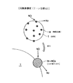
この直接還元型NOx触媒は、図7や図8に示すように、β型ゼオライト等の担体Tに触媒成分であるロジウム(Rh)やパラジウム(Pd)等の金属Mを担持させたもので、ディーゼルエンジン等の内燃機関の空燃比がリーン状態の排気ガスのように酸素濃度が高い雰囲気では、図7に示すように、NOxと接触して、NOxをN2 に還元すると共にこの触媒成分自体が酸化して酸化ロジウム等の酸化金属MOxとなる。この金属Mが全部酸化してしまうとNOxの還元能力が無くなるので、ある程度酸化された時点で再生させる必要がある。
【0017】
この再生は、空燃比が理論空燃比やリッチ状態の時のように、排気ガス中の酸素濃度を略ゼロ%に低い状態にして、図8に示すように、この酸化ロジウム等の酸化金属MOxを還元雰囲気で、未燃HCやCOや水素H2 等の還元剤と接触させて還元して金属Mに戻すことにより行なう。
【0018】
なお、この直接還元型NOx触媒においては、酸化金属MOxを還元する反応は他の触媒に比較して低温(例えば200℃以上)でも迅速に行なわれ、しかも、硫黄被毒の問題が少ないという利点がある。
【0019】
そして、更に、金属Mの酸化作用を軽減し、NOx還元能力の保持に寄与するセリウム(Ce)を配合し、下層に三元触媒を設けて酸化還元反応、特にリッチ状態におけるNOxの還元反応を促進するようにしている。また、NOxの浄化率を向上させるために担体に鉄(Fe)を加える等している。
【0020】
【発明が解決しようとする課題】
しかしながら、硫黄被毒がNOx吸蔵還元触媒に比べて少ないとはいうものの、燃料中の硫黄分により徐々に硫黄被毒して劣化する。即ち、担体に加えた鉄に、排気ガス中の硫黄分がSO2 として吸収されるので、この鉄によるNOxの浄化性能の向上が阻害される一次的な硫黄被毒が生じたり、更に、還元剤を含まない一定の温度の酸化雰囲気中で鉄から排出されたSO2 がSO3 に変化して、セリウムと化合するので、このセリウムによるNOx還元能力の保持に対する寄与が減少したりする二次的な硫黄被毒が生じて、NOxの浄化率が低下する。
【0021】
ただし、直接還元型NOx触媒においては、この硫黄被毒に対する触媒劣化回復に必要な触媒温度(硫黄パージ温度)は400℃程度であり、NOx吸蔵還元型触媒の650℃に比較して低く、通常の運転状態でも容易に達成することができる。
【0022】
この硫黄被毒による劣化が直接還元型NOx触媒で進展すると、排気ガスの空燃比がリーン状態で酸素濃度が高い雰囲気であっても、NOxをN2 に還元する能力が低下しているためNOxの浄化率が低下し、また、すぐにNOx還元能力が限界に近くまで低下するため、リッチ燃焼による再生処理を頻繁に行う必要が生じるので、燃費の悪化が生じる。
【0023】
そのため、直接還元型NOx触媒において、酸化金属MOxを還元雰囲気で、還元剤と接触させて還元して金属Mに戻す再生処理の他に、この硫黄被毒による劣化の進捗状態を監視し、劣化がある程度進捗した段階で、二次的な硫黄被毒を回避するために低酸素状態で、触媒の温度を400℃程度の硫黄パージ温度以上にして硫黄分を除去する硫黄パージによる触媒劣化回復処理を行う必要があり、強制的にこの触媒劣化回復処理を行っている。
【0024】
しかしながら、この硫黄パージにおいて、排気ガスを低酸素濃度にするリッチスパイク運転をすると、排気ガス中に未燃成分であるHC、COが多量に生成され、外部に排出されてしまうので、排気ガス浄化の面から好ましくないという問題がある。
【0025】
本発明は、上記の問題を解決するためになされたものであり、その目的は、上流側の直接還元型NOx触媒における硫黄被毒に対する触媒劣化回復処理の際に、発生するHC、COを利用して、下流側のDPFに捕集されているPMを燃焼除去できる排気ガス浄化システム及びその制御方法を提供することにある。
【0026】
【課題を解決するための手段】
以上のような目的を達成するための排気ガス浄化システムは、排気ガス中のNOxを浄化するための直接還元型NOx触媒と、排気ガス中のPMを浄化するための触媒付きDPFを、排気ガス通路に上流側から順に配置した排気ガス浄化システムにおいて、排気ガス中の酸素濃度を低くすると共に触媒温度を硫黄パージ温度以上に昇温する、前記直接還元型NOx触媒の硫黄被毒に対する触媒劣化回復処理中に、前記直接還元型NOx触媒と前記触媒付きDPFの間にエアを供給するエア供給システムを設けて構成される。
【0027】
この「直接還元型NOx触媒」とは、排気ガス中の酸素濃度が高い時に、触媒成分がNOx(窒素酸化物)をN2 (窒素)に還元すると共にこの触媒成分が酸化され、且つ、排気ガス中の酸素濃度が低下した時に、この触媒成分が還元される触媒のことをいい、この直接還元型NOx触媒は、β型ゼオライト等の担体に触媒成分であるロジウム(Rh)やパラジウム(Pd)等の特別な金属を担持させて構成することができる。
【0028】
そして、更に、この触媒成分の金属の酸化作用を軽減し、NOx還元能力の保持に寄与させるためにセリウム(Ce)を配合し、酸化還元反応、特にリッチ状態における放出されたNOxの還元反応を促進するために、下層に白金等を有する三元触媒を設けたり、また、NOxの浄化率を向上させるために担体に鉄(Fe)を加えたりして形成することができる。
【0029】
この触媒劣化回復処理は、直接還元型NOx触媒の硫黄被毒に対して、二次的な硫黄被毒を回避するために、排気ガス中の酸素濃度をほぼゼロにすると共に、排気ガス温度を昇温して触媒温度を硫黄が排出される硫黄パージ温度(約400℃程度)以上に昇温する処理であり、吸気絞り等の吸気量制御や後噴射等の燃料噴射制御やEGR制御等によるリッチスパイク制御によって実施することができる。
【0030】
また、上記の排気ガス浄化システムにおいて、前記エア供給システムは、ターボチャージャのコンプレッサによって過給される空気の一部を前記直接還元型NOx触媒と前記触媒付きDPFの間にエアを供給するように構成する。この構成により、比較的簡単なシステムで空気を供給することができる。
【0031】
そして、上記の排気ガス浄化システムにおける前記触媒付きDPFとしては、酸化触媒を有する様々な種類のDPFを利用できるが、酸化触媒をウォールフロータイプの壁表面に塗布して形成した触媒付きDPFや、酸化触媒とPM酸化触媒をウォールフロータイプの壁表面に塗布して形成した触媒付きDPFを用いることができる。また、前記触媒付きDPFの代わりに、上流側に酸化触媒を配置したDPFを用いることもできる。
【0032】
そして、上記の目的を達成するための排気ガス浄化システムの制御方法は、排気ガス中のNOxを浄化するための直接還元型NOx触媒と、排気ガス中のPMを浄化するための触媒付きDPFを、排気ガス通路に上流側から順に配置した排気ガス浄化システムの制御方法において、排気ガス中の酸素濃度を低くすると共に触媒温度を硫黄パージ温度以上に昇温する、前記直接還元型NOx触媒の硫黄被毒に対する触媒劣化回復処理中に、前記直接還元型NOx触媒と前記触媒付きDPFの間にエアを供給することを特徴とする。
【0033】
これらの構成によれば、直接還元型NOx触媒では、触媒劣化回復処理の硫黄パージを行う際に、二次的な硫黄被毒を回避するために、リッチスパイク運転をして、排気ガスを低酸素状態にするので、未燃焼成分HC、COが多量に排出され、同時に、リッチスパイク運転により排気ガス温度が上昇し、直接還元型NOx触媒の下流側では排気ガス温度が通常では400℃以上に上昇する。
【0034】
この時直接還元型NOx触媒の下流側にエア供給を行うと、下流側の触媒付きDPFの酸化触媒により、リッチスパイク運転で発生したHC、COが酸化するので、この酸化により、DPFに捕集されているPMが昇温し、PMは供給されるエア中のO2 で燃焼して除去され、DPFが再生される。
【0035】
従って、この上流側の直接還元型NOx触媒と下流側の触媒付きDPF(又は酸化触媒前置のDPF)を組み合わせてエア供給システムを設けた本発明の排気ガス浄化システムとその制御方法では、直接還元型NOx触媒の触媒劣化回復処理の硫黄パージの際に、直接還元型NOx触媒と触媒付きDPF(又は酸化触媒前置のDPF)の間にエアを供給することで、直接還元型NOx触媒の硫黄パージで発生する未燃HC、COの外部への排出を防止でき、しかも、同時に触媒付きDPFのPMを燃焼除去できる。
【0036】
【発明の実施の形態】
以下、図面を用いて、本発明に係る実施の形態の排気ガス浄化システム及びその制御方法について説明する。
【0037】
最初に、排気ガス浄化システムについて説明する。図1に示すように、この排気ガス浄化システム10は、エンジン本体1の排気ガス通路2に、上流側から順に直接還元型NOx触媒3と触媒付きDPF4を配置し、更に、この直接還元型NOx触媒3と触媒付きDPF4との間にエア供給口5aを有するエア供給システム5を設けて構成される。
【0038】
この直接還元型NOx触媒3は、図7や図8に示すように、β型ゼオライト等の担体Tにロジウム(Rh)やパラジウム(Pd)等の特別な金属Mを担持させて構成される。そして、更に、金属Mの酸化作用を軽減し、NOx還元能力の保持に寄与するセリウム(Ce)を配合し、下層に白金等を有する三元触媒を設けて酸化還元反応、特にリッチ状態におけるNOxの還元反応を促進するようにし、また、NOxの浄化率を向上させるために担体に鉄(Fe)を加えている。
【0039】
そして、この直接還元型NOx触媒3は、図7に示すように、ディーゼルエンジン等の内燃機関の空燃比がリーンの排気ガスのように酸素濃度が高い雰囲気では、NOxと接触して、NOxをN2 に還元すると共にこの金属M自体が酸化して酸化ロジウム(RhOx)等の酸化金属MOxとなり、図8に示すように、空燃比が理論空燃比やリッチ状態の時のように排気ガス中の酸素濃度が略ゼロ%の低い還元雰囲気の場合には、酸化金属MOxが、未燃HCやCOやH2 等の還元剤と接触して還元されてロジウム等の元の金属Mに戻る性質を有するものである。
【0040】
この触媒付きDPF4は、多孔質のコーディライト、あるいは、炭化ケイ素によって多数のガス通路(セル)が平行に形成され、この周囲を多孔質壁面で囲まれた多数の排気ガス通路の入口側と出口側を千鳥状に目封止して形成されるウォールフロータイプと呼ばれるハニカムフィルタや、セラミック繊維をステンレス多孔管に巻き付けて積層した繊維型フィルタ等で形成する。
【0041】
そして、酸化触媒付きのDPFの場合には、このフィルタの壁表面に白金(Pt)等の酸化触媒を塗布し、PM酸化触媒付きDPFの場合には、このフィルタの壁表面に白金等の酸化触媒と酸化セリウム(CeO2 )等のPM酸化触媒を塗布して形成される。
【0042】
これらの触媒付きDPF4は、未燃HC、COを190℃〜200℃の酸化雰囲気で燃焼することができる。
【0043】
また、エア供給システム5は、触媒付きDPF4の直前のエア供給口5aと、ターボ6のコンプレッサー6aの後流側のエア吸入口5bを連結するエア供給配管5cと、このエア供給配管5cに設けられたエア供給弁5dとを有して構成される。
【0044】
そして、エンジンの運転状態、主にトルクQとエンジン回転数Neを検出するトルクセンサや回転数センサ等からなる運転状況検出装置21が設けられる。また、排気ガス通路2の直接還元型NOx触媒3の上流側には空燃比Afを検知するための空燃比センサ22が、また、直接還元型NOx触媒3には触媒温度Tcat を検知するための触媒温度センサ23が、更に、下流側にはNOx濃度Cnox を検知するNOxセンサ24が設けられる。また、排気ガス温度を検知するための温度センサ25、26が、直接還元型NOx触媒3の上流側と、DPF4の下流側に設けられる。
【0045】
そして、運転状況検出装置21等から得られるエンジン1のトルク(負荷)Qやエンジン回転数Ne等を入力とし、燃料噴射制御等のエンジン全般の制御を行うエンジンコントロールユニット(ECU)と呼ばれる制御装置50を有して構成され、この制御装置50に直接還元型NOx触媒3の触媒再生制御や触媒劣化回復制御やDPF再生制御等を行なう排気ガス浄化システム制御手段200が設けられる。
【0046】
なお、吸気通路7には、エアクリーナー31と、ターボチャージャ6のコンプレッサ6aと、インタークーラ32と、吸気スロットル弁33が設けられ、更にEGR装置40として、EGR弁42とEGRクーラ43を有するEGR通路41と冷却水用配管44が設けられている。
【0047】
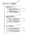
図2に示すように、この排気ガス浄化システム制御手段200は、触媒再生時期判定手段211や触媒再生処理制御手段212を含む触媒再生手段210と、硫黄パージ時期判定手段221や硫黄パージ処理制御手段222を含む触媒劣化回復手段220と、DPF再生時期判定手段231やDPF再生処理制御手段232を含むDPF再生手段230を有して構成される。
【0048】
この触媒再生手段210は、排気ガスの空燃比がリーン状態の酸素濃度が高い通常の運転状態で、NOxと接触してNOxをN2 に還元して酸化金属MOxとなった直接還元型NOx触媒3を、排気ガスの空燃比がリッチ状態の酸素濃度が低い状態で再生する手段であり、触媒再生時期判定手段211でこの触媒再生を行うタイミングを判定し、触媒再生時期であると判定した時に、触媒再生処理制御手段212で、空燃比が理論空燃比やリッチ状態の酸素濃度が略ゼロ%の状態の排気ガスを発生し、酸化金属MOxを還元雰囲気で未燃HCやCOやH2 等の還元剤と接触させて還元して金属Mに戻す。
【0049】
なお、この通常の運転状態とは、直接還元型NOx触媒3の再生処理用の運転や触媒劣化回復処理用の運転や触媒付きDPF4の再生処理等を行っていない時の、エンジンに要求されるトルクや回転数で運転する運転のことをいい、この通常の運転状態では、排気ガス中のNOxは直接還元型NOx触媒3により、直接N2 に還元されて浄化され、排気ガス中のPMは触媒付きDPF4による捕集及び燃焼除去により浄化される。
【0050】
この触媒再生時期判定手段211は、NOxを還元している時の直接還元型NOx触媒3の下流側の排気ガス中のNOx濃度Cnox や、酸素濃度が高い状態の経過時間や、NOxを還元している時に直接還元型NOx触媒3によって還元されるNOx量を推定演算した推定演算量等で、触媒再生時期であるか否かを判定する。
【0051】
また、触媒再生処理制御手段212は、排気ガス中の酸素濃度を低下させる手段、即ち、空燃比Afが14.7以下のリッチスパイク運転を行う手段であり、内燃機関の燃焼室に供給される燃料の噴射を制御する燃料噴射制御や、吸入空気量を制御する吸気量制御や、EGR装置のEGRガス量を制御するEGR制御等のいずれか一つまたはその組み合わせで行い、空燃比センサ22の検出値Afに基づいて、この検出値Afが所定の設定範囲内に入るようにフィードバック制御する。
【0052】
なお、燃料噴射制御には、エンジンの燃焼室に噴射する燃料の主噴射のタイミングを変更する主噴射タイミング制御や主噴射の後に後噴射(ポスト噴射)を行なう後噴射制御等があり、吸気量制御には、吸気スロットル弁33の弁開度を制御する吸気スロットル弁制御や、ターボチャージャ6のコンプレッサ6aからの吸気量を制御するターボチャージャ吸気量制御等がある。
【0053】
そして、触媒劣化回復手段220は、硫黄パージ時期判定手段221、硫黄パージ処理制御手段222を有して構成される。
【0054】
この硫黄パージ時期判定手段221は、硫黄パージ制御を行うか、行わないかを判定する手段であり、燃料消費量と燃料中の硫黄濃度から、直接還元型NOx触媒3に堆積される硫黄量X1を推定し、この推定した硫黄の堆積量X1を累積した累積値Xtが、硫黄パージ開始判定値X1より大きい場合に、硫黄パージ制御を開始するとの判定を行い、小さければ硫黄パージ制御を開始しないとの判定を行う。
【0055】
そして、硫黄パージ処理制御手段222は、硫黄の累積量Xtが限界X1に達し多時に、硫黄パージする必要があるとして、排気ガス中の酸素濃度を低くすると共に触媒温度Tcat を硫黄パージ温度Tr以上に昇温するリッチスパイク運転制御を行う手段であり、これにより、触媒温度Tcat を硫黄パージ温度Tr以上に昇温して、リッチ状態で二次的な硫黄被毒を防止しながら、硫黄パージを行って、触媒の劣化回復を行うものである。なお、この硫黄パージ運転におけるリッチスパイク運転は、再生処理のリッチスパイク運転と同様に、燃料噴射制御や吸気量制御やEGR制御等のいずれか一つまたはその組み合わせで行うことができる。
【0056】
そして、本発明においては、この硫黄パージ処理制御手段222は、DPF再生処理制御を含み、このDPF再生処理制御では、エア供給弁5dを開弁操作して、触媒付きDPF4の上流側に、ターボチャージャ6のコンプレッサ6a下流の過給空気の一部Aaを供給する。このエア供給により、硫黄パージ処理制御におけるリッチスパイク運転で発生する多量の未燃HC、COを、触媒付きDPF4の酸化触媒で酸化し、更に、これらのHC、COの酸化により発生した熱により、触媒付きDPF4に捕集されているPMを昇温させて、エア供給によって供給されるO2 で、燃焼除去する。
【0057】
つまり、硫黄パージの時に、リッチスパイク運転により排気ガス温度を上昇させ、直接還元型NOx触媒3の触媒温度Tcat を硫黄パージ温度(約400℃)以上に上昇させる。このとき、エア供給を行うことにより、リッチスパイク運転により発生した未燃HC、COを、触媒付きDPF4の酸化触媒の触媒作用により燃焼させることにより、触媒付きDPF4に捕集されたPMに流入する排気ガス温度を更に高く、一般的には500℃程度にすることができるので、このPMを燃焼させて、触媒付きDPF4のPMを除去して再生することができる。
【0058】
また、DPF再生手段230は、DPF再生時期判定手段231でDPFの目詰まりが進捗して触媒付きDPF4の再生処理が必要であると判定したら、DPF再生処理制御手段232で、再生処理制御を行って、触媒付きDPF4に捕集されたPMを燃焼除去する手段である。
【0059】
このDPF再生時期判定手段231は、DPF再生時期を判定する手段であり、エンジンの運転条件から触媒付きDPF4に堆積されるPM量を推定して積算することでPM蓄積量を算出し、このPM蓄積量が予め設定した判定値を超えた時に、DPF再生時期であると判定したり、あるいは、触媒付きDPF4の前後の排気圧力の差や比が判定値を超えた時に、DPF再生時期であると判定する。
【0060】
また、DPF再生処理制御手段232は、コモンレール等の電子制御式燃料噴射システムを利用して、噴射時期遅延や多段噴射等で排気ガス温度を上昇させたり、ポスト噴射や排気管内噴射によってフィルタに塗布した酸化触媒に燃料を供給して燃焼させて、排気ガス温度をPMの再燃焼温度以上に昇温させる等して、触媒付きDPF4の再生処理を行う。
【0061】
この再生処理は、リーン燃焼状態やエア供給システム5によるエア供給で、触媒付きDPF4に流入する排気ガス中の酸素濃度が高い状態で行われる。
【0062】
次に、上記の構成の排気ガス浄化システム10を、排気ガス浄化システム制御手段200により制御して、排気ガス中のNOx除去を行なう排気ガス浄化システム制御フローについて説明する。この制御フローは図3〜図5に例示するフローチャート等に基づいて行なわれる。
【0063】
この図3に示す排気ガス浄化システム制御フローは、ステップS100の触媒再生制御とステップS200の触媒劣化回復制御とステップS300のDPF再生制御からなり、エンジン全般を制御する全体のフローの一部として構成されるものであり、メインのエンジン制御フローで呼ばれて、エンジン制御フローと並行して実行され、エンジン運転の終了に伴って実行を中断し、メインのエンジン制御フローに戻って、このエンジン制御フローと共に終了するものとして示してある。
【0064】
そして、図3に示すように、この排気ガス浄化システム制御フローがスタートすると、ステップS100の触媒再生制御とステップS200の触媒劣化回復制御とステップS300のDPF再生制御が並行して実行され、エンジンの運転終了等のこの制御フローを終了する場合が生じると、この各ステップの制御内で終了の割り込みが生じリターンして、このフローに戻り、更に、図示しないメインのエンジン制御フローにリターンし、このフローを終了する。
【0065】
ステップS100の触媒再生制御は、図4の触媒再生制御フローに示すように、ステップS110で、直接還元型NOx触媒3によりNOxを浄化する通常運転制御を所定の時間(例えば、触媒再生制御を行うか否かを判定する時間間隔に相当する時間)の間行った後、ステップS120で直接還元型NOx触媒3が再生開始時期であるか否かを判定し、再生開始時期であれば、ステップS130の触媒再生処理制御を行ってから、また、再生開始時期でなければ、そのまま、ステップS110に戻り、この制御を繰り返す。そして、エンジンの運転終了等のこの制御フローを終了する場合が生じると、ステップS140の終了の割り込みが生じリターンして、図3の制御に戻る。
【0066】
そして、ステップS200の触媒劣化回復制御では、図5の触媒劣化回復制御フローに示すように、このフローがスタートすると、ステップS201で前回のエンジン運転で直接還元型NOx触媒3に累積した硫黄の累積量Xtをメモリーから読み込む。
【0067】
そして、ステップS202で、通常運転制御を所定の時間(例えば、触媒劣化回復制御を行うか否かを判定する時間間隔に相当する時間)の間行った後、このステップS202のエンジン運転による硫黄の堆積量Xaを、燃料消費量及び燃料中の硫黄濃度から算出し、この堆積量Xaを累積量Xtに加えて、新しい累積量Xtとする(Xt=Xt+Xa)。
【0068】
次のステップS203では、硫黄パージ開始時期であるか否かを、累積量Xtが所定のパージ開始判定値X1より大きいか否かで判定し、大きくない場合には、硫黄パージ開始時期に入っていないとして、ステップS202に戻る。
【0069】
ステップS203の判定で累積量Xtが所定のパージ開始判定値X1より大きい場合には、ステップS204の硫黄パージ運転制御を所定の時間の間行い、ステップS205で、直接還元型NOx触媒3の入口側の排気ガス温度Tg1が所定の判定温度T1(例えば、400℃)より大きい場合にはステップS206でエア供給を行ってから、また、小さい場合にはエア供給を行わずに、ステップS207に行く。なお、ステップS205の判定に排気ガス温度Tg1を用いたが, 代りに、触媒温度Tcat を用いることもできる。
【0070】
このステップS204の硫黄パージ運転制御は、リッチスパイク運転を行って、触媒温度Tcat を硫黄パージ温度以上にすると共に、排気ガス中の酸素濃度をゼロに近くして、SO3 の発生を防止して、セリウムの二次的な硫黄被毒を防止しながら、触媒劣化回復処理を行うものである
また、ステップS206のエア供給は、硫黄パージ運転制御のリッチスパイク運転によって発生する未燃HC、COを触媒付きDPF4の酸化触媒の触媒作用によって酸化して浄化すると共に、この酸化によって生じる熱により触媒付きDPF4捕集されたPMを昇温し、このPMを供給されたエアAa中のO2 で酸化し、触媒付きDPF4を再生するものである。
【0071】
次のステップS207では、硫黄パージで吐出される硫黄の吐出量Xsを、排気ガス量と触媒温度Tcat (又は、排気ガス温度Tg1)と予め入力した硫黄吐出量マップデータとから算出し、この吐出量Xsを累積量Xtから減算して、ステップS204の硫黄パージ運転制御を行った後の累積量Xtを求め、ステップS208の判定でこの累積量Xtが所定の第2判定値X2(通常はゼロ)以下でない場合には、ステップS204に戻って、累積量Xtが第2判定値X2以下になるまで硫黄パージ運転制御を継続し、ステップS208の判定で、この累積量Xtが第2判定値X2以下になったら、硫黄パージが完了したと判定して、ステップS209で硫黄パージ運転を停止し、通常の運転に戻る。なお、この時累積量Xtがマイナスの時はゼロとする。
【0072】
なお、この図5のフローでは、ステップS207とステップS208により累積量Xtが第2判定値X2以下になった時を硫黄パージ運転の終了の時としているが、燃料消費量と燃料中の硫黄濃度から算出した硫黄の累積量Xtと、硫黄パージ運転開始時の排気ガス量と触媒温度Tcat (又は、排気ガス温度Tg1)と予め入力された硫黄パージ運転時間マップデータとから、硫黄パージ運転時間を算出して、この運転時間の間硫黄パージ運転制御を行うようにしてもよい。
【0073】
このステップS209を終えると、ステップS202に戻り、このフローを繰り返す。そして、エンジンの運転終了等、この制御フローを終了する場合が生じると、ステップS210の終了の割り込みが生じ、ステップS211で、終了時の硫黄の累積量Xt、即ち、ステップS202やステップS207で算出された累積量Xtをメモリーへ書込んでから、図3のNOx浄化システム制御フローにリターンし、このフローを終了する。
【0074】
ステップS300のDPF再生制御は、図6のDPF再生制御フローに示すように、ステップS310で、PMを捕集する通常運転制御を所定の時間(例えば、DPF再生制御を行うか否かを判定する時間間隔に相当する時間)の間行った後、ステップS320で触媒付きDPF4が再生開始時期であるか否かを判定し、再生開始時期であれば、ステップS330のDPF再生処理制御を行ってから、また、再生開始時期でなければ、そのまま、ステップS310に戻り、この制御を繰り返す。そして、エンジンの運転終了等のこの制御フローを終了する場合が生じると、ステップS340の終了の割り込みが生じリターンして、図3の制御に戻る。
【0075】
そして、図4の触媒再生制御、図5の触媒劣化回復制御、図6のDPF再生制御が共に終了の割込みによりリターンして、図3の排気ガス浄化システム制御フローに戻ると、更に図示しないメインのエンジン制御フローに戻り、このエンジン制御フローの終了と共にこのNOx浄化システム制御フローも終了する。
【0076】
なお、上記のフローには示していないが、触媒再生処理制御、触媒パージ運転制御、DPF再生処理制御の何れかが重なる時は、予め設定された優先順序によってどれか一つを優先して行うものとする。
【0077】
これらの構成の排気ガス浄化システム10とその制御方法によれば、NOx浄化用の直接還元型NOx触媒3とPM浄化用の触媒付きDPF4を排気ガス通路2の上流側から順に配置し、これらの間にエア供給を行うエア供給システム5を設けることにより、直接還元型NOx触媒3の硫黄パージによる劣化回復処理時に、エアを触媒付きDPF4に供給して、硫黄パージのリッチスパイク運転で発生する未燃HC,COを酸化して浄化すると共に、この酸化によって発生する熱で、触媒付きDPF4に捕集され堆積されたPMをPM再燃焼温度以上に昇温し、燃焼除去できる。
【0078】
なお、上記では、DPFとして触媒付きDPFを例にして説明したが、触媒付きDPFの代わりに、酸化触媒をDPFの前に配置するタイプのDPFに対しても、本発明を適用することができる。
【0079】
この酸化触媒前置のDPFの場合には、前置する酸化触媒は、コーディエライト、炭化ケイ素、ステンレス等で形成されるハニカム構造に設けられた、上流側から下流側に貫通する多数のガス通路(セル)の壁面に、アルミナ、ゼオライト、シリカ等に白金等を担持させた貴金属触媒をコーティングして形成される。
【0080】
そして、エアは、この酸化触媒の上流側に供給され、未燃HC、COはこの酸化触媒で酸化され、酸化によって発生した熱により排気ガスが昇温し、この昇温した排気ガスにより、下流側のDPFが昇温し、このDPFに捕集されたPMが供給されたエア中のO2 により酸化されるので、これによりDPFが再生することになる。
【0081】
【発明の効果】
以上説明したように、本発明に係る排気ガス浄化システム及びその制御方法によれば、次のような効果を奏することができる。
【0082】
NOx浄化用の触媒として直接還元型NOx触媒を選択し、また、PM浄化用のDPFとして、触媒付きDPFや酸化触媒前置のDPFを選択して、排気ガス通路の上流側から順に配置し、更に、直接還元型NOx触媒の硫黄パージによる劣化回復処理時に、これらの間にエア供給を行うエア供給システムを設けることにより、エア供給により、硫黄パージのリッチスパイク運転で発生する未燃HC,COを酸化して浄化することができる。
【0083】
また、同時に、この未燃HC,COを酸化によって発生する熱で、触媒付きDPFや酸化触媒前置のDPFに捕集され堆積されたPMをPM再燃焼温度以上に昇温することができ、供給されたエア中のO2 で燃焼除去できる。
【0084】
従って、NOx浄化用の直接還元型NOx触媒の触媒劣化回復時に、PM浄化用のDPFの再生処理を行うことができるので、DPFの再生制御の回数を少なくすることができて、DPF再生処理による燃料の消費量の増加を抑制することができる。
【図面の簡単な説明】
【図1】本発明の実施の形態の排気ガス浄化システムを備えたエンジンの構成を示す図である。
【図2】本発明の実施の形態の排気ガス浄化システム制御手段の構成を示す図である。
【図3】本発明の実施の形態の排気ガス浄化システム制御フローの一例を示すフローチャートである。
【図4】図3の触媒再生制御フローの一例を示すフローチャートである。
【図5】図3の触媒劣化回復制御フローの一例を示すフローチャートである。
【図6】図3のDPF再生制御フローの一例を示すフローチャートである。
【図7】直接還元型NOx触媒の高酸素濃度状態における反応を示す模式図である。
【図8】直接還元型NOx触媒の低酸素濃度状態における反応を示す模式図である。
【符号の説明】
1 ディーゼルエンジン
2 排気ガス通路
3 直接還元型NOx触媒
4 触媒付きDPF
5 エア供給システム
6 ターボチャージャ
6a コンプレッサ
Aa エア[0001]
BACKGROUND OF THE INVENTION
The present invention relates to an exhaust gas purification system that reduces and purifies NOx in exhaust gas of an internal combustion engine, and collects and removes particulate matter in the exhaust gas, and a control method thereof. More specifically, the present invention relates to an exhaust gas purification system in which a direct reduction type NOx catalyst is disposed upstream for NOx purification, and an DPF with an oxidation catalyst is disposed downstream for PM purification, and a control method thereof.
[0002]
[Prior art]
Various studies and proposals have been made on exhaust gas purification systems for purifying particulate matter (particulate material: hereinafter referred to as PM) and NOx (nitrogen oxides) from exhaust gas of automobile internal combustion engines such as diesel engines. For PM, a filter called Diesel Particulate Filter (DPF) is developed, and for NOx, NOx reduction catalyst, three-way catalyst, etc. are developed. Yes.
[0003]
This DPF includes a DPF with an oxidation catalyst in which an oxidation catalyst such as platinum (Pt) is applied to the surface of a filter on a DPF that collects PM, and an oxidation catalyst such as platinum and cerium oxide (CeO).2There is a DPF with a catalyst such as a DPF with a PM oxidation catalyst in which a PM oxidation catalyst such as) is applied to the surface of the filter.
[0004]
In this DPF with an oxidation catalyst, NO2Oxidation of PM by O2NO is generated by oxidizing NO in the exhaust gas with an oxidation catalyst by utilizing the fact that the energy barrier is lower than oxidation by NO and can be performed at a low temperature.2Oxidize PM collected in CO and CO2PM is removed.
[0005]
Further, the DPF with a PM oxidation catalyst has a catalyst such as cerium oxide, and in the low temperature oxidation region (about 350 ° C. to 450 ° C.), NO is NO with the oxidation catalyst.2Oxidized into this NO2PM is oxidized by the catalyst, and in the intermediate temperature oxidation range (about 400 ° C to 600 ° C), the PM oxidation catalyst is used for O in the exhaust gas.2Is activated to directly oxidize PM, and the PM becomes O in the exhaust gas.2Oxygen in the exhaust gas in a high-temperature oxidation region (about 600 ° C or higher) above the temperature at which combustion occurs in2PM is oxidized by this.
[0006]
In addition, without applying an oxidation catalyst to the filter, an oxidation catalyst such as platinum is disposed upstream of the filter, and the upstream oxidation catalyst oxidizes NO in the exhaust gas, and the generated NO.2Then, the PM collected in the downstream DPF is oxidized to CO.2Some of them remove PM.
[0007]
In these DPF with catalyst and DPF before oxidation catalyst, catalyst, NO2By utilizing the oxidation of PM, the temperature at which PM can be oxidized is lowered, and oxidation is removed while collecting PM.
[0008]
However, even with these catalyst-equipped DPFs and DPFs in front of the oxidation catalyst, the exhaust gas still needs to be heated to about 350 ° C., so the exhaust gas temperature is insufficient in idling or low-load engine operating conditions. Since the catalyst is not activated, the above reaction does not occur, and PM is not oxidized but is deposited on the DPF. Therefore, the exhaust gas temperature is raised by injection timing delay, multistage injection, etc., or fuel is supplied to the oxidation catalyst by post injection or in-pipe injection and burned, and the PM is heated to a temperature higher than the reburning temperature and burned. For example, the DPF regeneration process is performed. At the time of regeneration of this DPF, it is necessary to make the PM collected in an oxidizing atmosphere at a relatively high oxygen concentration to the PM combustion temperature.
[0009]
On the other hand, regarding the NOx purification catalyst, one of them is a NOx occlusion reduction catalyst used in an exhaust gas purification apparatus for an internal combustion engine proposed in Japanese Patent Laid-Open No. 2000-274279. This NOx occlusion reduction catalyst is formed by supporting a noble metal catalyst such as platinum and an alkaline earth such as barium (Ba) on a catalyst carrier. In a high oxygen concentration atmosphere, NO in the exhaust gas is a noble metal catalyst. NOx is oxidized by catalytic action2Nitrate ion NOThree -And is absorbed in the form of nitrate.
[0010]
When the air-fuel ratio becomes rich and the oxygen concentration decreases, nitrate ions (NOThree -) NO2The unburned hydrocarbons (HC), CO and H contained in the exhaust gas are released by the catalytic action of the noble metal catalyst.2NO with a reducing agent such as2Is N2Reduced to This reduction action can prevent NOx from being released into the atmosphere.
[0011]
Therefore, in the exhaust emission control device of Japanese Patent Application Laid-Open No. 2000-274279, when the air-fuel ratio of the inflowing exhaust gas is lean, NOx is absorbed by the NOx occlusion reduction type catalyst, and when the NOx absorption capacity approaches saturation, the exhaust gas A regeneration process is performed to make the air-fuel ratio of the exhaust air the stoichiometric air-fuel ratio or rich, and the absorbed NOx is released by lowering the oxygen concentration of the inflowing exhaust gas, the released NOx is reduced, and the NOx is purified. ing.
[0012]
However, at the time of this regeneration treatment, it is necessary to reduce the released NOx with a noble metal catalyst. However, since a very large amount of NOx is released in a short time, the total amount of NOx even if an appropriate amount of reducing agent is supplied. Is reliably brought into contact with the reducing agent and the noble metal catalyst.2However, it is difficult to reduce the amount of NOx, and part of the NOx leaks, so that there is a problem in that there is a limit in reducing NOx.
[0013]
Furthermore, since the catalytic function is deteriorated by sulfur contained in the fuel of the diesel engine, there is a problem of sulfur poisoning that it is difficult to maintain a high NOx purification rate for a long time.
[0014]
In the sulfur purge for recovering the deterioration state due to the sulfur poisoning, it is necessary to raise the catalyst temperature to 650 ° C. In a diesel engine, in order to increase the catalyst temperature to 650 ° C. or higher, It is necessary to raise the exhaust gas temperature to 600 ° C. or higher. However, even if exhaust gas temperature raising control such as intake throttling or rich combustion is performed, it is practically difficult to raise the catalyst temperature to 650 ° C. only by engine control.
[0015]
On the other hand, a patent application NO. 19992481 and NO. There is a catalyst (hereinafter referred to as a direct reduction type NOx catalyst) that directly reduces NOx described in 20000617.
[0016]
As shown in FIG. 7 and FIG. 8, this direct reduction type NOx catalyst is obtained by supporting a metal M such as rhodium (Rh) or palladium (Pd) as a catalyst component on a carrier T such as β-type zeolite, In an atmosphere having a high oxygen concentration such as exhaust gas in which the air-fuel ratio of an internal combustion engine such as a diesel engine is in a lean state, as shown in FIG.2The catalyst component itself is oxidized to a metal oxide MOx such as rhodium oxide. If this metal M is completely oxidized, the ability to reduce NOx is lost, so it is necessary to regenerate it when it is oxidized to some extent.
[0017]
This regeneration is performed by setting the oxygen concentration in the exhaust gas to a low level of approximately zero% as in the case where the air-fuel ratio is the stoichiometric air-fuel ratio or rich state, and as shown in FIG. In a reducing atmosphere, unburned HC, CO, and hydrogen H2It reduces by making it contact with reducing agents, such as, and returning to the metal M.
[0018]
In this direct reduction type NOx catalyst, the reaction for reducing the metal oxide MOx is carried out rapidly even at a low temperature (for example, 200 ° C. or higher) as compared with other catalysts, and there are few advantages of sulfur poisoning. There is.
[0019]
Further, cerium (Ce) that contributes to maintaining the NOx reduction ability is reduced by reducing the oxidation action of the metal M, and a three-way catalyst is provided in the lower layer to perform the oxidation-reduction reaction, particularly the reduction reaction of NOx in a rich state. Try to promote. Further, iron (Fe) is added to the carrier in order to improve the NOx purification rate.
[0020]
[Problems to be solved by the invention]
However, although the sulfur poisoning is less than that of the NOx occlusion reduction catalyst, the sulfur content in the fuel gradually deteriorates due to sulfur poisoning. That is, the sulfur added in the exhaust gas is added to the iron added to the carrier.2As a result, primary sulfur poisoning that impedes the improvement in NOx purification performance by iron occurs, and SO discharged from iron in an oxidizing atmosphere at a constant temperature not containing a reducing agent.2Is SOThreeTherefore, secondary sulfur poisoning in which the contribution of the cerium to the retention of the NOx reduction ability is reduced, and the NOx purification rate is lowered.
[0021]
However, in the direct reduction type NOx catalyst, the catalyst temperature (sulfur purge temperature) necessary for recovery of the catalyst deterioration against this sulfur poisoning is about 400 ° C., which is lower than the 650 ° C. of the NOx storage reduction type catalyst. It can be easily achieved even in the driving state.
[0022]
When the deterioration due to sulfur poisoning progresses in the direct reduction NOx catalyst, NOx is reduced to N even in an atmosphere where the air-fuel ratio of the exhaust gas is lean and the oxygen concentration is high2The NOx purification rate is reduced because the ability to reduce to NO is reduced, and the NOx reduction ability is immediately reduced to near the limit, so that it is necessary to frequently perform regeneration processing by rich combustion. Deterioration occurs.
[0023]
Therefore, in the direct reduction type NOx catalyst, in addition to the regeneration process in which the metal oxide MOx is reduced in contact with a reducing agent in a reducing atmosphere and returned to the metal M, the progress of deterioration due to sulfur poisoning is monitored, In order to avoid secondary sulfur poisoning at a certain stage, the catalyst deterioration recovery process by sulfur purge is performed in a low oxygen state to remove the sulfur content by setting the catalyst temperature to a sulfur purge temperature of about 400 ° C. or higher. The catalyst deterioration recovery process is forcibly performed.
[0024]
However, in this sulfur purge, if rich spike operation is performed to reduce the exhaust gas to a low oxygen concentration, a large amount of unburned components HC and CO are generated in the exhaust gas and discharged to the outside. There is a problem that it is not preferable from the viewpoint of.
[0025]
The present invention has been made to solve the above-mentioned problems, and its purpose is to utilize HC and CO generated during the catalyst deterioration recovery process for sulfur poisoning in the upstream direct reduction NOx catalyst. An object of the present invention is to provide an exhaust gas purification system capable of burning and removing PM trapped in the downstream DPF and a control method therefor.
[0026]
[Means for Solving the Problems]
To achieve the above objectivesExhaust gasThe purification system is an exhaust gas purification system in which a direct reduction type NOx catalyst for purifying NOx in exhaust gas and a DPF with a catalyst for purifying PM in exhaust gas are sequentially arranged in the exhaust gas passage from the upstream side. InLower the oxygen concentration in the exhaust gas and raise the catalyst temperature above the sulfur purge temperature,An air supply system is provided to supply air between the direct reduction NOx catalyst and the DPF with catalyst during the catalyst deterioration recovery process for sulfur poisoning of the direct reduction NOx catalyst.
[0027]
This “direct reduction type NOx catalyst” is a catalyst component that converts NOx (nitrogen oxide) into N when the oxygen concentration in the exhaust gas is high.2This catalyst component is reduced when it is reduced to (nitrogen) and this catalyst component is oxidized, and the oxygen concentration in the exhaust gas is reduced. This direct reduction type NOx catalyst is a β-type catalyst. A special metal such as rhodium (Rh) or palladium (Pd) as a catalyst component may be supported on a support such as zeolite.
[0028]
Further, cerium (Ce) is blended in order to reduce the metal oxidizing action of the catalyst component and contribute to maintaining the NOx reduction ability, and the oxidation reduction reaction, particularly the reduction reaction of released NOx in the rich state. In order to promote, a three-way catalyst having platinum or the like in the lower layer can be provided, or in order to improve the NOx purification rate, iron (Fe) can be added to the support.
[0029]
This catalyst deterioration recovery process reduces the oxygen concentration in the exhaust gas to almost zero and reduces the exhaust gas temperature in order to avoid secondary sulfur poisoning against the sulfur poisoning of the direct reduction NOx catalyst. This is a process to raise the catalyst temperature above the sulfur purge temperature (about 400 ° C.) at which sulfur is discharged, and is based on intake air amount control such as intake throttle, fuel injection control such as post-injection, EGR control, etc. It can be implemented by rich spike control.
[0030]
Also aboveExhaust gasIn the purification system, the air supply system is configured to supply a part of the air supercharged by a turbocharger compressor between the direct reduction NOx catalyst and the DPF with catalyst. With this configuration, air can be supplied with a relatively simple system.
[0031]
And aboveExhaust gasAs the DPF with catalyst in the purification system, various types of DPF having an oxidation catalyst can be used. However, the DPF with catalyst formed by applying the oxidation catalyst to the wall surface of the wall flow type, the oxidation catalyst and the PM oxidation catalyst. A DPF with a catalyst formed by applying to a wall flow type wall surface can be used. Moreover, DPF which has arrange | positioned the oxidation catalyst upstream can also be used instead of the said DPF with a catalyst.
[0032]
And to achieve the above objectiveExhaust gasThe control method of the purification system is an exhaust gas in which a direct reduction type NOx catalyst for purifying NOx in exhaust gas and a DPF with catalyst for purifying PM in exhaust gas are arranged in order from the upstream side in the exhaust gas passage. Gas purification systemControl methodInLower the oxygen concentration in the exhaust gas and raise the catalyst temperature above the sulfur purge temperature,During the catalyst deterioration recovery process for sulfur poisoning of the direct reduction type NOx catalyst, air is supplied between the direct reduction type NOx catalyst and the DPF with catalyst.
[0033]
According to these configurations, in the direct reduction type NOx catalyst, when performing the sulfur purge for the catalyst deterioration recovery process, in order to avoid secondary sulfur poisoning, the rich spike operation is performed to reduce the exhaust gas. Since it is in the oxygen state, a large amount of unburned components HC and CO are discharged, and at the same time, the exhaust gas temperature rises due to the rich spike operation, and the exhaust gas temperature is usually 400 ° C. or more on the downstream side of the direct reduction NOx catalyst. To rise.
[0034]
At this time, if air is supplied to the downstream side of the direct reduction type NOx catalyst, HC and CO generated in the rich spike operation are oxidized by the oxidation catalyst of the downstream catalyst-attached DPF. The temperature of the heated PM rises, and the PM is O in the supplied air.2The DPF is regenerated by burning and removing.
[0035]
Therefore, in the exhaust gas purification system of the present invention in which the air supply system is provided by combining the upstream direct reduction NOx catalyst and the downstream catalyst-attached DPF (or the DPF in front of the oxidation catalyst) and the control method thereof, In the sulfur purge of the catalyst deterioration recovery process of the reduced NOx catalyst, by supplying air between the directly reduced NOx catalyst and the DPF with catalyst (or the DPF in front of the oxidation catalyst), the direct reduced NOx catalyst Unburned HC and CO generated by sulfur purge can be prevented from being discharged to the outside, and at the same time, PM of the DPF with catalyst can be burned and removed.
[0036]
DETAILED DESCRIPTION OF THE INVENTION
Hereinafter, an exhaust gas purification system and a control method thereof according to an embodiment of the present invention will be described with reference to the drawings.
[0037]
First, the exhaust gas purification system will be described. As shown in FIG. 1, in this exhaust
[0038]
As shown in FIGS. 7 and 8, the direct
[0039]
Then, as shown in FIG. 7, the direct reduction
[0040]
The
[0041]
In the case of a DPF with an oxidation catalyst, an oxidation catalyst such as platinum (Pt) is applied to the wall surface of the filter. In the case of a DPF with a PM oxidation catalyst, oxidation of platinum or the like is applied to the wall surface of the filter. Catalyst and cerium oxide (CeO2) Or the like is applied to form a PM oxidation catalyst.
[0042]
These DPF4 with a catalyst can burn unburned HC and CO in an oxidizing atmosphere of 190 ° C to 200 ° C.
[0043]
The
[0044]
And the driving | running
[0045]
A control device called an engine control unit (ECU) that performs overall engine control such as fuel injection control using the torque (load) Q of the
[0046]
The intake passage 7 is provided with an
[0047]
As shown in FIG. 2, the exhaust gas purification system control means 200 includes a catalyst regeneration means 210 including a catalyst regeneration timing determination means 211 and a catalyst regeneration processing control means 212, a sulfur purge timing determination means 221 and a sulfur purge processing control means. And a catalyst deterioration recovery means 220 including 222, and a DPF regeneration means 230 including a DPF regeneration timing determination means 231 and a DPF regeneration processing control means 232.
[0048]
This catalyst regeneration means 210 is in a normal operation state in which the exhaust gas air-fuel ratio is lean and the oxygen concentration is high, and in contact with NOx, NOx is reduced to N2The direct reduction
[0049]
This normal operating state is required for the engine when the operation for regeneration processing of the direct
[0050]
The catalyst regeneration timing determination means 211 reduces NOx concentration Cnox in the exhaust gas downstream of the direct
[0051]
The catalyst regeneration processing control means 212 is means for reducing the oxygen concentration in the exhaust gas, that is, means for performing a rich spike operation in which the air-fuel ratio Af is 14.7 or less, and is supplied to the combustion chamber of the internal combustion engine. The fuel injection control for controlling the fuel injection, the intake air amount control for controlling the intake air amount, the EGR control for controlling the EGR gas amount of the EGR device, or the like is performed, or a combination thereof. Based on the detected value Af, feedback control is performed so that the detected value Af falls within a predetermined setting range.
[0052]
Fuel injection control includes main injection timing control for changing the timing of main injection of fuel injected into the combustion chamber of the engine, post-injection control for performing post-injection (post-injection) after main injection, and the like. The control includes intake throttle valve control for controlling the valve opening degree of the intake throttle valve 33, turbocharger intake air amount control for controlling the intake air amount from the
[0053]
The catalyst deterioration recovery means 220 includes a sulfur purge timing determination means 221 and a sulfur purge processing control means 222.
[0054]
This sulfur purge timing determination means 221 is a means for determining whether or not to perform sulfur purge control. From the fuel consumption amount and the sulfur concentration in the fuel, the sulfur amount X1 directly deposited on the reduced
[0055]
Then, the sulfur purge processing control means 222 assumes that the cumulative amount of sulfur Xt reaches the limit X1 and needs to purge the sulfur at many times, so that the oxygen concentration in the exhaust gas is lowered and the catalyst temperature Tcat is set to the sulfur purge temperature Tr or higher. In this way, the catalyst temperature Tcat is raised to a temperature equal to or higher than the sulfur purge temperature Tr to prevent secondary sulfur poisoning in a rich state, and the sulfur purge is performed. To recover the deterioration of the catalyst. Note that the rich spike operation in the sulfur purge operation can be performed by any one or a combination of fuel injection control, intake air amount control, EGR control, and the like, similarly to the rich spike operation of the regeneration process.
[0056]
In the present invention, the sulfur purge processing control means 222 includes DPF regeneration processing control. In this DPF regeneration processing control, the
[0057]
That is, at the time of sulfur purge, the exhaust gas temperature is raised by rich spike operation, and the catalyst temperature Tcat of the direct reduction
[0058]
When the DPF regeneration timing determination unit 231 determines that the DPF clogging has progressed and the regeneration process of the
[0059]
The DPF regeneration timing determining means 231 is a means for determining the DPF regeneration timing. The PM accumulation amount is calculated by estimating and integrating the PM amount accumulated on the
[0060]
The DPF regeneration processing control means 232 uses an electronically controlled fuel injection system such as a common rail to increase the exhaust gas temperature by delaying the injection timing, multistage injection, etc., or applying it to the filter by post injection or injection in the exhaust pipe The regeneration of the
[0061]
This regeneration process is performed in a lean combustion state or air supply by the
[0062]
Next, an exhaust gas purification system control flow in which the exhaust
[0063]
The exhaust gas purification system control flow shown in FIG. 3 includes catalyst regeneration control in step S100, catalyst deterioration recovery control in step S200, and DPF regeneration control in step S300, and is configured as part of the overall flow for controlling the entire engine. It is called in the main engine control flow, is executed in parallel with the engine control flow, interrupts execution when the engine operation ends, returns to the main engine control flow, and this engine control It is shown as ending with the flow.
[0064]
As shown in FIG. 3, when this exhaust gas purification system control flow is started, the catalyst regeneration control in step S100, the catalyst deterioration recovery control in step S200, and the DPF regeneration control in step S300 are executed in parallel, and the engine When there is a case where the control flow such as the end of the operation is terminated, an end interruption is generated in the control of each step, the flow returns to this flow, and the flow returns to the main engine control flow (not shown). End the flow.
[0065]
In the catalyst regeneration control in step S100, as shown in the catalyst regeneration control flow of FIG. 4, in step S110, normal operation control for purifying NOx by the direct reduction
[0066]
In the catalyst deterioration recovery control in step S200, as shown in the catalyst deterioration recovery control flow in FIG. 5, when this flow starts, the accumulation of sulfur accumulated in the direct reduction
[0067]
In step S202, normal operation control is performed for a predetermined time (for example, a time corresponding to a time interval for determining whether or not to perform catalyst deterioration recovery control), and then sulfur in the engine operation in step S202 is performed. The accumulation amount Xa is calculated from the fuel consumption amount and the sulfur concentration in the fuel, and this accumulation amount Xa is added to the accumulation amount Xt to obtain a new accumulation amount Xt (Xt = Xt + Xa).
[0068]
In the next step S203, it is determined whether or not it is the sulfur purge start timing based on whether or not the cumulative amount Xt is larger than a predetermined purge start determination value X1, and if not, the sulfur purge start timing is entered. If not, the process returns to step S202.
[0069]
If the cumulative amount Xt is larger than the predetermined purge start determination value X1 in the determination in step S203, the sulfur purge operation control in step S204 is performed for a predetermined time, and in step S205, the direct reduction
[0070]
In the sulfur purge operation control in step S204, the rich spike operation is performed to set the catalyst temperature Tcat to the sulfur purge temperature or higher and the oxygen concentration in the exhaust gas to be close to zero.ThreeThe catalyst deterioration recovery treatment is performed while preventing secondary sulfur poisoning of cerium.
Further, the air supply in step S206 is performed by oxidizing and purifying unburned HC and CO generated by the rich spike operation of the sulfur purge operation control by the catalytic action of the oxidation catalyst of the
[0071]
In the next step S207, the sulfur discharge amount Xs discharged by the sulfur purge is calculated from the exhaust gas amount, the catalyst temperature Tcat (or the exhaust gas temperature Tg1), and the sulfur discharge amount map data inputted in advance, and this discharge The amount Xs is subtracted from the accumulated amount Xt to obtain the accumulated amount Xt after the sulfur purge operation control in step S204 is performed, and the accumulated amount Xt is determined to be a predetermined second determination value X2 (usually zero in step S208). If not, the flow returns to step S204 to continue the sulfur purge operation control until the cumulative amount Xt becomes equal to or smaller than the second determination value X2, and in step S208, the cumulative amount Xt becomes the second determination value X2. If it becomes below, it will determine with sulfur purge having been completed, a sulfur purge driving | operation will be stopped by step S209, and it will return to a normal driving | operation. At this time, when the cumulative amount Xt is negative, it is zero.
[0072]
In the flow of FIG. 5, the time when the cumulative amount Xt becomes equal to or smaller than the second determination value X2 in step S207 and step S208 is the end of the sulfur purge operation, but the fuel consumption amount and the sulfur concentration in the fuel From the cumulative sulfur amount Xt calculated from the above, the exhaust gas amount at the start of the sulfur purge operation, the catalyst temperature Tcat (or the exhaust gas temperature Tg1), and the sulfur purge operation time map data input in advance, the sulfur purge operation time is calculated. It may be calculated and the sulfur purge operation control may be performed during this operation time.
[0073]
When step S209 ends, the process returns to step S202, and this flow is repeated. When this control flow is terminated, such as when the engine is terminated, an interruption of termination of step S210 occurs, and in step S211, the cumulative amount of sulfur Xt at the end, that is, calculation in step S202 or step S207. After writing the accumulated amount Xt to the memory, the process returns to the NOx purification system control flow of FIG. 3 and ends this flow.
[0074]
In the DPF regeneration control in step S300, as shown in the DPF regeneration control flow in FIG. 6, in step S310, it is determined whether normal operation control for collecting PM is performed for a predetermined time (for example, whether to perform DPF regeneration control). In step S320, it is determined whether or not the
[0075]
When the catalyst regeneration control in FIG. 4, the catalyst deterioration recovery control in FIG. 5, and the DPF regeneration control in FIG. 6 are all returned upon interruption, and the process returns to the exhaust gas purification system control flow in FIG. The engine control flow is returned to, and the NOx purification system control flow is also terminated when the engine control flow is terminated.
[0076]
Although not shown in the above flow, when any one of the catalyst regeneration process control, the catalyst purge operation control, and the DPF regeneration process control overlaps, one of them is prioritized according to a preset priority order. Shall.
[0077]
According to the exhaust
[0078]
In the above description, the DPF with a catalyst is described as an example of the DPF. However, the present invention can be applied to a DPF in which an oxidation catalyst is disposed in front of the DPF instead of the DPF with a catalyst. .
[0079]
In the case of this oxidation catalyst pre-positioned DPF, the pre-oxidation catalyst is composed of a number of gases penetrating from the upstream side to the downstream side provided in a honeycomb structure formed of cordierite, silicon carbide, stainless steel, or the like. The wall surface of the passage (cell) is formed by coating a noble metal catalyst in which platinum or the like is supported on alumina, zeolite, silica or the like.
[0080]
The air is supplied to the upstream side of the oxidation catalyst, the unburned HC and CO are oxidized by the oxidation catalyst, the exhaust gas is heated by the heat generated by the oxidation, and the heated exhaust gas is downstream. The temperature of the DPF on the side rises, and the O in the air supplied with the PM collected in the DPF2As a result, the DPF is regenerated.
[0081]
【The invention's effect】
As described above, according to the exhaust gas purification system and the control method thereof according to the present invention, the following effects can be achieved.
[0082]
Select a direct reduction NOx catalyst as the NOx purification catalyst, select a DPF with catalyst or a DPF in front of the oxidation catalyst as the DPF for PM purification, and arrange them in order from the upstream side of the exhaust gas passage, Further, by providing an air supply system for supplying air between them during the deterioration recovery process by sulfur purging of the direct reduction type NOx catalyst, unburned HC, CO generated in the rich spike operation of sulfur purging by air supply. Can be oxidized and purified.
[0083]
At the same time, the heat generated by oxidation of the unburned HC and CO can raise the PM collected and deposited in the DPF with catalyst and the DPF in front of the oxidation catalyst to a temperature higher than the PM recombustion temperature, O in supplied air2Can be removed by combustion.
[0084]
Accordingly, when the catalyst deterioration recovery of the direct reduction NOx catalyst for NOx purification is recovered, the regeneration process for the DPF for PM purification can be performed, so that the number of DPF regeneration controls can be reduced and the DPF regeneration process can be performed. An increase in fuel consumption can be suppressed.
[Brief description of the drawings]
FIG. 1 is a diagram showing a configuration of an engine including an exhaust gas purification system according to an embodiment of the present invention.
FIG. 2 is a diagram showing a configuration of exhaust gas purification system control means according to an embodiment of the present invention.
FIG. 3 is a flowchart showing an example of an exhaust gas purification system control flow according to the embodiment of the present invention.
4 is a flowchart showing an example of a catalyst regeneration control flow of FIG.
FIG. 5 is a flowchart showing an example of a catalyst deterioration recovery control flow in FIG. 3;
6 is a flowchart showing an example of a DPF regeneration control flow of FIG.
FIG. 7 is a schematic view showing a reaction of a direct reduction NOx catalyst in a high oxygen concentration state.
FIG. 8 is a schematic diagram showing a reaction in a low oxygen concentration state of a direct reduction NOx catalyst.
[Explanation of symbols]
1 Diesel engine
2 Exhaust gas passage
3 Direct reduction NOx catalyst
4 DPF with catalyst
5 Air supply system
6 Turbocharger
6a Compressor
Aa Air
Claims (6)
Priority Applications (5)
| Application Number | Priority Date | Filing Date | Title |
|---|---|---|---|
| JP2002093872A JP4093301B2 (en) | 2002-03-29 | 2002-03-29 | Exhaust gas purification system and control method thereof |
| DE60314611T DE60314611T2 (en) | 2002-03-29 | 2003-03-28 | EXHAUST GAS DETECTION SYSTEM AND METHOD FOR CONTROLLING THEREOF |
| EP03745438A EP1491735B1 (en) | 2002-03-29 | 2003-03-28 | Exhaust gas decontamination system and method of controlling the same |
| US10/508,551 US20050153828A1 (en) | 2002-03-29 | 2003-03-28 | Exhaust gas decontamination system and method of controlling the same |
| PCT/JP2003/003936 WO2003083272A1 (en) | 2002-03-29 | 2003-03-28 | Exhaust gas decontamination system and method of controlling the same |
Applications Claiming Priority (1)
| Application Number | Priority Date | Filing Date | Title |
|---|---|---|---|
| JP2002093872A JP4093301B2 (en) | 2002-03-29 | 2002-03-29 | Exhaust gas purification system and control method thereof |
Publications (2)
| Publication Number | Publication Date |
|---|---|
| JP2003286832A JP2003286832A (en) | 2003-10-10 |
| JP4093301B2 true JP4093301B2 (en) | 2008-06-04 |
Family
ID=28671769
Family Applications (1)
| Application Number | Title | Priority Date | Filing Date |
|---|---|---|---|
| JP2002093872A Expired - Fee Related JP4093301B2 (en) | 2002-03-29 | 2002-03-29 | Exhaust gas purification system and control method thereof |
Country Status (5)
| Country | Link |
|---|---|
| US (1) | US20050153828A1 (en) |
| EP (1) | EP1491735B1 (en) |
| JP (1) | JP4093301B2 (en) |
| DE (1) | DE60314611T2 (en) |
| WO (1) | WO2003083272A1 (en) |
Families Citing this family (41)
| Publication number | Priority date | Publication date | Assignee | Title |
|---|---|---|---|---|
| JP2004324454A (en) * | 2003-04-22 | 2004-11-18 | Mitsubishi Motors Corp | Exhaust emission control device of internal combustion engine |
| DE10350485A1 (en) | 2003-10-29 | 2005-06-02 | Robert Bosch Gmbh | Method for operating an internal combustion engine |
| DE10361791A1 (en) * | 2003-12-31 | 2005-07-28 | Volkswagen Ag | Exhaust gas cleaning device regenerating method for e.g. Otto engine, involves exhibiting catalyst by device, and pressuring filter with secondary air, when catalyst is desulphurized with hypostoichiometric exhaust gas |
| JP4389739B2 (en) * | 2004-09-29 | 2009-12-24 | 三菱自動車工業株式会社 | Internal combustion engine with a supercharger |
| US7386676B2 (en) * | 2005-01-21 | 2008-06-10 | International Buiness Machines Coporation | Data coherence system |
| JP2007113497A (en) * | 2005-10-20 | 2007-05-10 | Toyota Motor Corp | Exhaust emission control device of internal combustion engine |
| US8082733B2 (en) | 2005-11-18 | 2011-12-27 | Borgwarner Inc. | Air handling system with after-treatment |
| DE102005062398B4 (en) * | 2005-12-23 | 2016-02-04 | Volkswagen Ag | Regenerating a particulate filter with an oxidation catalytic coating |
| US20070283697A1 (en) * | 2006-06-08 | 2007-12-13 | Deere & Company, A Delaware Corporation | Internal combustion engine including charged combustion air duct to a particulate filter |
| US8117832B2 (en) | 2006-06-19 | 2012-02-21 | Donaldson Company, Inc. | Exhaust treatment device with electric regeneration system |
| FR2907844A1 (en) * | 2006-10-27 | 2008-05-02 | Renault Sas | Particle filter passive regeneration method for motor vehicle, involves removing gas mixture in inlet line during normal functioning phase of internal combustion engine to introduce mixture in exhaust line in upstream of particle filter |
| EP2097630B1 (en) * | 2006-12-22 | 2016-06-08 | Volvo Group North America, Inc. | Method and apparatus for controlling exhaust temperature of a diesel engine |
| DE102007054227A1 (en) * | 2007-11-12 | 2009-05-14 | Man Nutzfahrzeuge Ag | Internal combustion engine with EGR cooler |
| DE102007057603B4 (en) * | 2007-11-28 | 2023-03-23 | Volkswagen Ag | Method for operating an internal combustion engine with an exhaust gas turbocharger |
| EP2072774A1 (en) * | 2007-12-18 | 2009-06-24 | Delphi Technologies, Inc. | Compression ignition engine comprising a three way catalyst device |
| US20090173062A1 (en) * | 2008-01-04 | 2009-07-09 | Caterpillar Inc. | Engine system having valve actuated filter regeneration |
| FR2928176B1 (en) * | 2008-02-29 | 2016-12-23 | Faurecia Systemes D'echappement | METHOD FOR REGENERATING A PARTICLE FILTER FOR A GASOLINE ENGINE AND ASSOCIATED EXHAUST ASSEMBLY |
| DE102008000793A1 (en) * | 2008-03-20 | 2009-09-24 | Robert Bosch Gmbh | Process for the regeneration of a diesel particulate filter of an internal combustion engine and corresponding device |
| US20090241541A1 (en) * | 2008-03-25 | 2009-10-01 | International Truck Intellectual Property Company, Llc | Pre-turbo exahust filtration system for internal combustion engines |
| FR2931514A3 (en) * | 2008-05-22 | 2009-11-27 | Renault Sas | Exhaust gas post-treatment device e.g. particle filter, regenerating method for diesel engine of motor vehicle, involves utilizing low pressure turbocompressor for supplying air via exhaust pipe in upstream of post-treatment device |
| JP5293941B2 (en) * | 2008-06-11 | 2013-09-18 | 株式会社Ihi | Regeneration method of dust collection filter |
| US8776502B2 (en) * | 2008-07-03 | 2014-07-15 | Donaldson Company, Inc. | System and method for regenerating an auxiliary power unit exhaust filter |
| DE102008036284B4 (en) * | 2008-08-04 | 2013-09-12 | Dr. Ing. H.C. F. Porsche Aktiengesellschaft | Powertrain for a motor vehicle |
| JP4688941B2 (en) * | 2008-08-05 | 2011-05-25 | 本田技研工業株式会社 | Catalyst deterioration judgment device |
| US8844270B2 (en) * | 2009-01-16 | 2014-09-30 | Donaldson Company, Inc. | Diesel particulate filter regeneration system including shore station |
| US8607549B2 (en) * | 2009-07-31 | 2013-12-17 | Ford Global Technologies, Llc | Controlling regeneration of an emission control device |
| US8302387B2 (en) * | 2009-08-25 | 2012-11-06 | International Engine Intellectual Property Company, Llc | Method and apparatus for de-sulfurization on a diesel oxidation catalyst |
| DE102009043087B4 (en) * | 2009-09-25 | 2023-08-03 | Volkswagen Ag | Internal combustion engine with secondary air supply and a method for operating this |
| DE102010006309A1 (en) * | 2010-01-22 | 2011-07-28 | Dr. Ing. h.c. F. Porsche Aktiengesellschaft, 70435 | Combustion engine i.e. diesel engine, for passenger car, has supercharger comprising two compressor stages and turbine stage, where one of compressor stages is connected with exhaust system downstream to turbine stage |
| JP2011220158A (en) | 2010-04-07 | 2011-11-04 | Ud Trucks Corp | Exhaust emission control device for engine |
| DE102010044102A1 (en) * | 2010-11-18 | 2012-05-24 | Ford Global Technologies, Llc | Exhaust system for internal combustion engines with particle filter |
| US20130000297A1 (en) * | 2011-06-29 | 2013-01-03 | Electro-Motive Diesel, Inc. | Emissions reduction system |
| DE102012101767B4 (en) | 2012-03-02 | 2015-01-08 | Pierburg Gmbh | Internal combustion engine |
| JP2015048767A (en) * | 2013-08-30 | 2015-03-16 | 本田技研工業株式会社 | Control device for internal combustion engine |
| WO2015120618A1 (en) * | 2014-02-14 | 2015-08-20 | Tenneco Automotive Operating Company Inc. | Exhaust treatment system with soot blower |
| US10100689B2 (en) * | 2015-03-27 | 2018-10-16 | Cummins Inc. | Systems and methods for desulfation of an oxidation catalyst for dual fuel engines |
| DE102016208289A1 (en) * | 2016-02-29 | 2017-08-31 | Volkswagen Aktiengesellschaft | Internal combustion engine with a spark-ignited internal combustion engine and method for operating such an internal combustion engine |
| EP3631176B1 (en) | 2017-06-02 | 2022-08-10 | Volvo Truck Corporation | A method for controlling the temperature of a nox controlling component and an exhaust after treatment system |
| US10309278B2 (en) * | 2017-10-03 | 2019-06-04 | GM Global Technology Operations LLC | Method for desulfurization of selective catalytic reduction devices |
| WO2019142011A1 (en) * | 2018-01-16 | 2019-07-25 | Carrier Corporation | Exhaust gas temperature control |
| US10781737B1 (en) * | 2019-03-14 | 2020-09-22 | Southwest Research Institute | Regeneration of automotive exhaust aftertreatment device using diverted boost air during deceleration |
Family Cites Families (12)
| Publication number | Priority date | Publication date | Assignee | Title |
|---|---|---|---|---|
| DE3013445A1 (en) * | 1980-04-05 | 1981-10-08 | Bosch und Pierburg System oHG, 4040 Neuss | Automobile engine exhaust emission level reduction system - using lambda probe for fuel mixture regulation and catalytic after burning |
| DE4410489C1 (en) * | 1994-03-25 | 1995-10-05 | Daimler Benz Ag | Method to regulate air/fuel mixture ratio for IC engine |
| JP3434117B2 (en) * | 1996-03-29 | 2003-08-04 | 住友電気工業株式会社 | Particulate trap for diesel engine |
| JP3228232B2 (en) * | 1998-07-28 | 2001-11-12 | トヨタ自動車株式会社 | Exhaust gas purification device for internal combustion engine |
| DE19901760A1 (en) * | 1999-01-18 | 2000-07-27 | Emitec Emissionstechnologie | Method and arrangement for cleaning an exhaust gas stream of a gasoline engine flowing in an exhaust line |
| JP3633349B2 (en) | 1999-03-19 | 2005-03-30 | トヨタ自動車株式会社 | Exhaust gas purification device for internal combustion engine |
| JP2001115829A (en) * | 1999-10-15 | 2001-04-24 | Mitsubishi Motors Corp | Exhaust emission control device for internal combustion engine |
| JP2001149758A (en) * | 1999-11-22 | 2001-06-05 | Valtion Teknillinen Tukimuskeskus | Catalyst and method for catalycally recomposing nitrogen oxides |
| JP3911951B2 (en) * | 2000-02-29 | 2007-05-09 | 日産自動車株式会社 | Exhaust gas purification device and exhaust gas purification method for internal combustion engine |
| AU2001287753A1 (en) * | 2000-09-18 | 2002-03-26 | Isuzu Motors Limited | Catalyst and method for the catalytic reduction of nitrogen oxides |
| JP3767483B2 (en) * | 2002-01-08 | 2006-04-19 | 日産自動車株式会社 | Exhaust gas purification device for internal combustion engine |
| US6915629B2 (en) * | 2002-03-07 | 2005-07-12 | General Motors Corporation | After-treatment system and method for reducing emissions in diesel engine exhaust |
-
2002
- 2002-03-29 JP JP2002093872A patent/JP4093301B2/en not_active Expired - Fee Related
-
2003
- 2003-03-28 DE DE60314611T patent/DE60314611T2/en not_active Expired - Lifetime
- 2003-03-28 WO PCT/JP2003/003936 patent/WO2003083272A1/en active IP Right Grant
- 2003-03-28 EP EP03745438A patent/EP1491735B1/en not_active Expired - Fee Related
- 2003-03-28 US US10/508,551 patent/US20050153828A1/en not_active Abandoned
Also Published As
| Publication number | Publication date |
|---|---|
| EP1491735A1 (en) | 2004-12-29 |
| DE60314611T2 (en) | 2008-02-28 |
| DE60314611D1 (en) | 2007-08-09 |
| WO2003083272A1 (en) | 2003-10-09 |
| JP2003286832A (en) | 2003-10-10 |
| US20050153828A1 (en) | 2005-07-14 |
| EP1491735B1 (en) | 2007-06-27 |
| EP1491735A4 (en) | 2006-10-11 |
Similar Documents
| Publication | Publication Date | Title |
|---|---|---|
| JP4093301B2 (en) | Exhaust gas purification system and control method thereof | |
| JP4304447B2 (en) | Exhaust gas purification method and exhaust gas purification system | |
| JP3829699B2 (en) | Exhaust gas purification system and its regeneration control method | |
| EP1793099B1 (en) | Method of exhaust gas purification and exhaust gas purification system | |
| JP4140636B2 (en) | Exhaust gas purification method and exhaust gas purification system | |
| WO2007060785A1 (en) | Method for control of exhaust gas purification system, and exhaust gas purification system | |
| WO2006123510A1 (en) | Exhaust gas purification method and exhaust gas purification system | |
| JP3201237B2 (en) | Exhaust gas purification device for internal combustion engine | |
| EP1637717B1 (en) | Exhaust gas cleaning method and exhaust gas cleaning system | |
| JP2004108320A (en) | Method and system for exhaust emission control | |
| JP4083453B2 (en) | NOx purification system and catalyst deterioration recovery method thereof | |
| WO2007110997A1 (en) | METHOD OF CONTROLLING NOx PURIFICATION SYSTEM AND NOx PURIFICATION SYSTEM | |
| JP4168781B2 (en) | NOx catalyst regeneration method for NOx purification system and NOx purification system | |
| JP2003254042A (en) | Exhaust emission control device for internal combustion engine | |
| JP4561467B2 (en) | Exhaust gas purification method and exhaust gas purification system | |
| JP3925357B2 (en) | Control method of exhaust gas purification system | |
| JP4613787B2 (en) | Exhaust gas purification device for internal combustion engine | |
| JP2003166412A (en) | Control method for generation of exhaust emission control device | |
| JP2003020930A (en) | Exhaust emission control device for internal combustion engine | |
| JP3747793B2 (en) | Fuel injection control method and regeneration control method for continuous regeneration type diesel particulate filter system | |
| JP4070687B2 (en) | Exhaust purification device | |
| JP3876905B2 (en) | Desulfurization control method for exhaust gas purification system and exhaust gas purification system | |
| JP4442373B2 (en) | Exhaust gas purification method and exhaust gas purification system | |
| JP4403868B2 (en) | Exhaust gas purification system control method and exhaust gas purification system | |
| JP3899820B2 (en) | Exhaust gas purification device for internal combustion engine |
Legal Events
| Date | Code | Title | Description |
|---|---|---|---|
| A621 | Written request for application examination |
Free format text: JAPANESE INTERMEDIATE CODE: A621 Effective date: 20050325 |
|
| A131 | Notification of reasons for refusal |
Free format text: JAPANESE INTERMEDIATE CODE: A131 Effective date: 20071030 |
|
| A521 | Request for written amendment filed |
Free format text: JAPANESE INTERMEDIATE CODE: A523 Effective date: 20071225 |
|
| TRDD | Decision of grant or rejection written | ||
| A01 | Written decision to grant a patent or to grant a registration (utility model) |
Free format text: JAPANESE INTERMEDIATE CODE: A01 Effective date: 20080212 |
|
| A61 | First payment of annual fees (during grant procedure) |
Free format text: JAPANESE INTERMEDIATE CODE: A61 Effective date: 20080226 |
|
| FPAY | Renewal fee payment (event date is renewal date of database) |
Free format text: PAYMENT UNTIL: 20110314 Year of fee payment: 3 |
|
| R150 | Certificate of patent or registration of utility model |
Free format text: JAPANESE INTERMEDIATE CODE: R150 |
|
| LAPS | Cancellation because of no payment of annual fees |