JP4092420B2 - Parts storage box for gaming machines - Google Patents
Parts storage box for gaming machines Download PDFInfo
- Publication number
- JP4092420B2 JP4092420B2 JP08695098A JP8695098A JP4092420B2 JP 4092420 B2 JP4092420 B2 JP 4092420B2 JP 08695098 A JP08695098 A JP 08695098A JP 8695098 A JP8695098 A JP 8695098A JP 4092420 B2 JP4092420 B2 JP 4092420B2
- Authority
- JP
- Japan
- Prior art keywords
- screw
- cover
- storage box
- caulking
- tightening screw
- Prior art date
- Legal status (The legal status is an assumption and is not a legal conclusion. Google has not performed a legal analysis and makes no representation as to the accuracy of the status listed.)
- Expired - Lifetime
Links
Images


Landscapes
- Pinball Game Machines (AREA)
Description
【0001】
【発明の属する技術分野】
本発明は遊技機に装着される電気部品(基板等)その他の部品を収納するのに用いる遊技機用部品収納ボックスに関し、詳しくは、当該部品収納ボックスの封止手段に関する。
【0002】
【従来の技術】
遊技ホールに設置されているいわゆるパチンコ遊技を実施するための弾球遊技機やその他の据置型遊技機(スロットマシン、カードゲーム機等)には、数多くの電気部品やデリケートな構造のパーツ類(弾球遊技機における賞球払出し装置等)が装備されている。これら部品のうち、例えば種々の遊技装置類の動作を電気的に制御するために構築された回路基板等は、防塵性や組付け作業性の観点から、通常、所定の収納ボックス(筐体)に収納された状態で遊技機に配置されている。
【0003】
ところで、遊技機に対する深刻な不正行為として、回路基板を収納するボックス(以下「基板収納ボックス」という。)を開けて内部のROM等の電気部品を付け替えたり、あるいは、基板収納ボックス(回路基板)に付随するコネクタの配線パターンから別の不正基板に接続させるといった行為等がある。このような不正行為を防止する対策として、典型的には図16に示すように、遊技機(特に弾球遊技機)に装着する基板収納ボックス100は、筐体本体部101および当該筐体本体部101に装填した回路基板等を遮蔽するために当該筐体本体部101に被せるカバー102の一部(典型的には周縁部)に、それぞれ、ねじ穴101aおよびビス装着孔102aを設けておくと共に、そこにワンウェイビス106(即ち一方向規制ネジ)を装着してネジ穴101aに締め付けていた。すなわち、ワンウェイビス106の頭部は回動工具(ドライバ等)による締め付けが容易である一方で弛め方向に対する回動工具との係合は困難となる形状に成形されており、不正遊技者によるビス106の意図的な弛めおよび引き抜き(挿入方向とは逆方向に引き抜かれること。以下同じ。)を困難なものとしている。さらに、筐体本体部101とカバー102とが締着された後には、通常、図17に示すような塞ぎプラグ104(典型的には合成樹脂製)が上記ビス装着孔102aに填め込まれている。すなわち、図16および図17に示すように、塞ぎプラグ104に設けられた挿入部105先端の係合片105aを、予めビス装着孔102aの内壁面に設けられた段差に係合することによって取り外し不能な状態で当該ビス装着孔102aに装着されている。これにより、ビス装着孔102aの開口部が塞ぎプラグ104の天板部107によって塞がれて外部からワンウェイビス106頭部に直接回動工具等を触れさせないように工夫がこらされている(図16)。
【0004】
【発明が解決しようとする課題】
しかしながら、図16に示すような従来の基板収納ボックス100における筐体本体部101とカバー102との封止手段によっても不正遊技者の不正行為を完全に防止することは困難であった。すなわち、不正遊技者による特殊な操作および/または処理によって、上述の塞ぎプラグ104が取り外されたり或いは上記ワンウェイビス106が弛められたり引き抜かれたりする場合があった。
【0005】
本発明は、上述の基板収納ボックス等の遊技機用部品収納ボックスにおける従来の封止手段に係る問題点を解決するものであり、その目的とするところは、防犯上の観点からボックス内部が一旦封止(密閉)された後には外部から不正に再開放されないことを実現するカバーと筐体本体部との封止手段、および、そのような封止手段によって密閉された遊技機用部品ボックスを提供することである。
【0006】
【課題を解決するための手段】
【0007】
【0008】
【0009】
【0010】
上記目的を達成するため、本発明は、遊技機に装着される部品を収納するボックスであって、遊技機の部品を収納する筐体本体部と、当該収納された部品を外部から遮蔽するようにして当該筐体本体部に被せられるカバーとを備えており、そのカバーは当該筐体本体部と当該カバーとを貫通した状態で装着された締め付けネジと当該締め付けネジ先端の貫通した側に配置された抜け止めナット具との係合によって当該筐体本体部に固定されており、ここで当該抜け止めナット具には、当該貫通状態で装着された締め付けネジの引き抜きを阻止するための係止ナット部材が備えられており、その係止ナット部材に当該締め付けネジの一部が係合することによって当該筐体本体部に対する当該カバーの固定状態の維持が実現される遊技機用部品収納ボックス(以下「本発明の第三の部品収納ボックス」という。)を提供する。
【0011】
本発明の第三の部品収納ボックスでは、上記かしめ部材に代えて締め付けネジと抜け止めナット具との係合によって筐体本体部にカバーを固定するとともに、当該抜け止めナット具に備えられた係止ナット部材によって上記貫通状態の締め付けネジの引き抜きを防止している。これにより、本発明の第三の部品収納ボックスでは、筐体本体部の部品装填部分を外部から遮蔽するようにして当該筐体本体部に固定されたカバーの当該筐体本体部に対する固定状態を維持することができる。このため、本発明の第三の部品収納ボックスによっても、上記締め付けネジの引き抜きに基づく上記筐体本体部とカバーとの再開放を防止し、当該再開放による不正行為の発生を防止することができる。
【0012】
また、本発明は、上述の本発明の第三の部品収納ボックスをさらに好ましくしたものとして、上記締め付けネジの軸部は雄ねじの形成された先端ねじ部とねじの形成されていない中央部とを有しており、上記抜け止めナット具の中空部には当該雄ねじに対応する雌ねじが形成されており、ここで当該締め付けネジと当該抜け止めナット具とは、当該締め付けネジが当該抜け止めナット具に対して完全に締め込まれたときに当該締め付けネジの先端ねじ部が当該抜け止めナット具の中空部を突き抜けて螺合しないように構成されており、かつ、上記係止ナット部材は当該締め付けネジが当該抜け止めナット具に対して完全に締め込まれたときに当該締め付けネジ中央部の一部と係合するように設けられている遊技機用部品収納ボックス(以下「本発明の第四の部品収納ボックス」という。)を提供する。
【0013】
本発明の第四の部品収納ボックスでは、上記カバーが筐体本体部に固定されている状態(即ち締め付けネジが抜け止めナット具に対して完全に締め込まれている状態)において、上記締め付けネジと抜け止めナット具との螺合(ねじの嵌め合わせ)が解除され、当該先端部は抜け止めナット具の反対側に突き抜けている。このため、本発明の第四の部品収納ボックスでは、たとえ不正遊技者が抜け止めナット具に対して完全に締め込まれた状態の締め付けネジを弛め方向に回転させることに成功し得た場合であっても、締め付けネジが抜け止めナット具と螺合されていない結果、当該締め付けネジはその位置で空回りするのみである。さらにこのとき、締め付けネジの上記中央部において、当該締め付けネジが係止ナット部材に係合するため、当該締め付けネジの引き抜き方向への移動を阻むことができる。従って、本発明の第四の部品収納ボックスによれば、上記締め付けネジの引き抜きに基づく上記筐体本体部とカバーとの再開放を更に効果的に防止し得、当該再開放による不正行為の発生を未然に防止することができる。
【0014】
【発明の実施の形態】
以下、遊技機としての一典型例である弾球遊技機(パチンコ機)に装備される本発明の部品収納ボックス(上記第三、第四の部品収納ボックスを包含する。以下同じ。)の好適な一実施形態を図面を参照しつつ説明する。先ず、本発明の第三および第四の部品収納ボックスの構成とほぼ同じ構成を有する第一および第二の部品収納ボックスとして好適な一実施形態を説明する。なお、図1は、本実施形態に係る部品収納ボックス10を装備した弾球遊技機1の裏面構成を示す背面図である。
【0015】
本実施形態に係る弾球遊技機1は、長方形枠状に成形された木枠3の前面に額縁状に成形されたベース枠および金枠(いずれも図示せず)を備え、その内側に遊技盤面(即ち、釘や風車等を適当に配置した遊技領域)を配備した通常の形式の弾球遊技機1である。図1に示すように、この弾球遊技機1の裏面側には、遊技球発射装置8や機構板7が脱着可能に装着されている。この機構板7には、外部電源に接続される配電盤4、賞球タンク5、賞球払出し装置9等のいわゆるパチンコ遊技を実施するために必要な種々の装置類が備えられている。また、賞球払い出し装置9の下方には、これら機構板7に装備される装置類および弾球遊技機1の正面側に配備される図示しない電気部品(装飾灯等)の動作を制御するための枠制御装置(制御回路基板等)を収納する基板収納ボックス11が装備されている。なお、機構板7に装着される上記装置類は、一般的な弾球遊技機で通常使用され得るものであればよく、本発明を特定する事項ではないため、詳細な説明は省略する。
【0016】
一方、機構板7のほぼ中央には弾球遊技機1の裏面側から遊技盤6が装着されている。この遊技盤6は、弾球遊技機1における上記遊技盤面を構成するためのものであり、所定のパチンコ遊技内容に基づいて各種の遊技装置(例えば、変動入賞装置、図柄表示装置、音源、装飾灯、等)が備えられている。而して、この遊技盤6の背面部(すなわち弾球遊技機1の裏面側)には、上記遊技盤面上に配備される上述の各種遊技装置類を所定のプログラムに基づいて作動させるための回路基板(図示せず)を収納した本実施形態に係る部品収納ボックス10(以下「本基板収納ボックス10」という。)が装着されている。以下、本弾球遊技機1に装備される本基板収納ボックス10について詳細に説明する。
【0017】
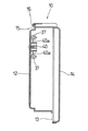
図2は、弾球遊技機1の遊技盤6背面部に装着した状態における本基板収納ボックス10の外形を示した正面図である。また、図3は図2におけるIII −III線矢視断面図である。これら図面から明らかなように、本基板収納ボックス10は中空状の筐体であり、その基本骨格は上述の従来の一般的な基板収納ボックス100と同様である(図16参照)。すなわち、本基板収納ボックス10は中空状の筐体であって、そのボックス本体は、半透明若しくは不透明な合成樹脂からなる筐体本体部14とカバー12とから構成されている。図2および図3に示すように、この筐体本体部14(即ち基台)は枠状に成型されており、その内側には回路基板13や静電気遮断用シールド板(図示せず)等がビスその他の結合手段によって装填されている。なお、この回路基板13には各種の素子類(図示せず)や当該回路基板13と外部の電気部品(典型的には上記遊技盤6に装備される装置類や枠制御装置)とを電気的に接続するためのコネクタ類21が装着されており、本弾球遊技機1におけるメイン制御部を構成している。また、筐体本体部14の一方の端部(図2の上側)には支持軸16が設けられており、後述するカバー12に設けられたフック片15と係合される。また、図2に示すように、筐体本体部14の左右側面には、それぞれ上下一対をなす係止ピン18が突出して設けられている。而して、これら係止ピン18を遊技盤6の裏面側に設けられた図示しない係合片と係合させることによって、本基板収納ボックス10の弾球遊技機1への装着が行われる。ところで、筐体本体部14の端部の二ヶ所には後述するカバー12を当該筐体本体部14に被せて固定するためのカバー固定部25が連結片25bを介して設けられている(後述する図4参照)。このカバー固定部25については後述する。
【0018】
次に本基板収納ボックス10のカバー12について説明する。図2に示すように、本実施形態にかかるカバー12は、筐体本体部14の表面のほぼ全体を被覆するものであり、一つの天板部とその四方に形成された側壁部とから成る一体に成型された合成樹脂製の蓋状部材である。このカバー12の側壁部の一端には上記支持軸16に回動可能に係合し得るフック片15が形成されている。而して、図3に示すように、当該フック片15を上記支持軸16に係合することによって、当該カバー12は筐体本体部14に対して回動可能に軸着される。また、図1および図2に示すように、このカバー12の天板部および側壁部には、本基板収納ボックス10内で発生した熱を外部に放散するための小孔形状の放熱口17が多数形成されている。これにより、カバー12が被せられて密閉された本基板収納ボックス10の内部で発生した熱をカバー12を開放することなく外部に放散することができる。また、カバー12の天板部には機種名その他のインフォメーションを表示するシール貼付部19a,19bが設けられている(図2)。ところで、本実施形態にかかるカバー12には、当該カバー12を筐体本体部14に被せた際の上記カバー固定部25に対応する位置に封止部28が連結片28bを介して設けられている(後述する図4参照)。この封止部28の構造については後述する。
【0019】
次に、本発明を特徴付けるカバー12の筐体本体部14への固定手段について詳述する。なお、図4および図5は、本基板収納ボックス10の要部(図2における右下部)を示す一部破断した斜視図である。また、図6は上記カバー固定部25と封止部28との締結状況を模式的に示す断面図であり、(A)、(B)、(C)および(D)は、カバー固定部25と封止部28とが締結されていく状態を連続的に示している。図2および図4に示すように、筐体本体部14に設けられた上記カバー固定部25は、大まかにいって、円状の中空を有する角柱状に形成された4つの同形状の締着部25aと当該締着部25aを各々筐体本体部14の側壁部に連結する連結片25bと当該4つの締着部25aを並列させて連結する補助連結片25cとから構成されている。なお、カバー固定部25を構成するこれら部材は、筐体本体部14自体と同様の合成樹脂から一体に形成され得る。一方、図2および図4に示すように、カバー12に設けられた上記封止部28は、大まかにいって、方形状の中空を有する角柱状に形成された4つの同形状のビス取付部28aと該ビス取付部28aを各々カバー12の側壁部に連結する連結片28bとから構成されている。なお、封止部28を構成するこれら部材は、カバー12自体と同様の合成樹脂から一体に形成され得る。
【0020】
次に、カバー固定部25および封止部28に関する上記各構成部材の形状について詳しく説明する。図6(A)に示すように、筐体本体部14に設けられたカバー固定部25の締着部25aに形成された上記円状中空は、内径の小さい締着材貫通部分25dとその下方に連続して形成されている当該締着材貫通部分25dよりも内径の大きな締着材かしめ部分25eとから構成されている。而して、締着材かしめ部分25eの下縁部すなわち締着部25aの一方の開口部には、当該開口部を塞ぐための合成樹脂から成る遮蔽板26が接着剤等の一般的なボンディング手段によって固着されている。一方、図6(A)に示すように、カバー12に設けられた封止部28のビス取付部28aに設けられた上記方形状中空は、後述するかしめ部材30およびかしめ用ビス35の挿入開口部に相当する締着材装着部分28cとその下方に連続して形成されている当該締着材装着部分28cよりも内径の小さな締着材貫通部分28d(ここは円状中空である)とから構成されている。なお、この締着材貫通部分28dの内径と上記締着部25aにおける締着材貫通部分25dの内径とはほぼ同一となるように形成されている(後述する他の実施形態についても同様である。)。また、締着材装着部分28cの内壁の一部には凹部28eが形成されており、後述する塞ぎプラグ37の係合片38aを嵌入・係合させることができる(後述の図5および図6(D)参照)。
【0021】
次に、本実施形態にかかるかしめ部材30およびかしめ用ビス35の構造について説明する。図4および図6(A)に示すように、本実施形態にかかるかしめ部材30は、大径の方形状に成形された頭部30aとそれより小径の円筒形状に成形された軸部30bとからなる一般的なリベット様の外形を有し、かつ、その軸方向の中心部には図示しない雌ねじの形成された円筒状中空部が形成されたナット具形状のかしめ部材30である。このかしめ部材30は典型的にはアルミニウムその他の延性の高い金属材から成型されており、その頭部30aの形状および外径は上記ビス取付部28aにおける締着材装着部分28cに丁度挿入され得る形状およびサイズであって上記締着材貫通部分28dには入り込めない形状およびサイズ(典型的には当該締着材装着部分28cと同じ方形状およびサイズ)に調整されている。他方、軸部30bの形状および外径は上記締着材貫通部分28dに丁度挿入され得る形状およびサイズ(典型的には当該締着材貫通部分28dと同じサイズ)に形成されている。なお、上述のとおり、本実施形態にかかるかしめ部材30の頭部30aが方形・角柱状に形成されており、装着部位において不用意な回転を起こさせないように配慮されている。ところで、図6(A)に示すように、このかしめ部材30の軸部30bの先端部分30c(以下「軸先端部30c」という。)は中空部の内側に膨らむようにやや肉厚に形成されており、結果、当該軸先端部30cにおける中空部の内径は他の部分よりも狭くなっている。なお、このかしめ部材30の軸部30bは、上記封止部28の締着材貫通部分28dと上記カバー固定部25の締着材貫通部分25dとを貫通し得、さらにこれら部分28d,25dを貫通した位置において後述するようにして軸先端部30cが外方に広がり得る程度の長さに調整されている。
【0022】
而して、このかしめ部材30の中空部には当該中空部の雌ねじに対応する雄ねじの形成されたかしめ用ビス35が装着される。すなわち、図4および図6(A)に示すように、このかしめ用ビス35は、通常のビスやボルトと同様、大径の頭部35aと雄ねじの形成された小径の軸部35bとから構成されている。なお、本実施形態においては、当該かしめ用ビス35として上述のワンウェイビス形状のものを使用しているが、本実施形態の実施にワンウェイビスの使用は必須ではない。このかしめ用ビス35は一般的な鉄材から成型されており、その頭部35aの外径は上記ビス取付部28aにおける締着材装着部分28cに丁度挿入され得るサイズであって上記かしめ部材30の中空部には入り込めないサイズに形成されている。
【0023】
次に、上記かしめ部材30およびかしめ用ビス35を用いたカバー12の筐体本体部14に対する固定方法を詳述する。図6(A)に示すように、予め、かしめ用ビス35をかしめ部材30の中空部に差し込んで螺合させたもの(但し上記軸先端部30cに至る所まで螺合させてはならない。)をカバー12封止部28における上記締着材装着部分28cに挿入する。このとき、当該締着材装着部分28cの内径とほぼ同じサイズの上記かしめ部材30の頭部30aが当該締着材装着部分28cの内壁部に接触することによっていわゆる仮圧入状態が保たれる。この結果、この状態で本基板収納ボックス10(カバー12)をひっくり返しても当該かしめ部材30およびかしめ用ビス35が締着材装着部分28cから脱落することはない。
【0024】
次に、図4および図6(B)に示すように、仮圧入状態のかしめ部材30およびかしめ用ビス35をドライバWによってさらに奥に押し込み、封止部28の締着材貫通部分28dおよびカバー固定部25の締着材貫通部分25dを一気に貫通させる。このとき、上述のとおり、かしめ部材30の頭部30aは封止部28締着材貫通部分28dに入り込むことができず、結果、当該締着材貫通部分28dを構成する壁面上部がかしめ部材30頭部30aの出っ張り部分下部に接触する位置(即ち図6(B)および図4に示す位置)で当該かしめ部材30およびかしめ用ビス35の押し込みは終了する。而して、この位置で、図6(C)に示すように、かしめ用ビス35をドライバWによって締め込んでいく。ここで、上述のとおり、かしめ部材30の軸先端部30cは中空部が狭くなっている。このため、かしめ用ビス35がさらに締め込まれて(螺合されて)当該部分にまでかしめ用ビス35先端部が進行してきた際には、かしめ部材30軸先端部30cは当該進行してきたかしめ用ビス35によって締め付けられ上方に引っ張られるとともにその先端部によって押し広げられる格好となり、結果、カバー固定部25締着部25aの締着材かしめ部分25eに貫通しているかしめ部材30軸先端部30cは、その貫通した位置から外方に広げられる(図6(C)および図5参照)。
これにより、かしめ部材30のかしめが完了し、カバー12の筐体本体部14への固定が完了する。而して、かしめ完了後、図5および図6(D)に示すように、塞ぎプラグ37を締着材装着部分28cに挿入し、かしめ用ビス35およびかしめ部材30を外部から遮蔽する。すなわち、図7に示すように、この塞ぎプラグ37は締着材装着部分28cの形状・サイズにほぼ適合した方形状の天板部39と当該天板部39から下方に延伸する二本の挿入部38とから構成されている。この挿入部38の先端部は外方に向けたくちばし状の係合片38aを形成しており、締着材装着部分28cに当該塞ぎプラグ37を挿入した際には、この係合片38aが上述の凹部28eに填り込みつつ当該凹部28eの側壁と係合し、結果、当該塞ぎプラグ37の不用意な脱落を防止する。また、天板部39の上面はドーム状の曲面を構成しており、不正遊技者が使用するような針金状の異物のひっかかりを防止している。
【0025】
上述のように、封止部28およびカバー固定部25を構成し、それらを上述のかしめ部材30で締結した結果、たとえ不正遊技者が塞ぎプラグ37を取り除いてかしめ用ネジ35を弛め、あるいは抜き去ることに成功したとしても、それに連動して典型的にはアルミニウム製のかしめ部材30のかしめ状態(即ち上記軸先端部30cの末広がり状態)が弛緩することはない。また、このような典型的にはアルミニウム製の本発明に係るかしめ部材30を用いた結果、上記かしめ用ネジ35を弛めるためのトルク値は従前の締め付け手段によって締め付けられている従来のビス106(図16参照)を弛めるためのトルク値よりも高くなり、種々の不正な処理によってもその値は低下し難い。また、カバー固定部25締着部25aにおける締着材かしめ部分25eの開口部には遮蔽板26が固着しており、不正遊技者がかしめ部材30の外方に広がった軸先端部30cに直接触れたり、何らかの操作を行うことを防いでいる。このため、本基板収納ボックス10では、上記かしめ部材30によってカバー12の筐体本体部14に対する固定状態を維持することができるため、カバー12の不正な再開放を防ぎ、当該ボックス10の封止状態(密閉状態)を保つことができる。
【0026】
なお、上述のとおり、本基板収納ボックス10には、計二ヶ所に上記封止部28およびカバー固定部25が設けられており、それぞれ四つのビス取付部28aおよび締着部25aが備えられている(図2参照)。しかしながら、カバー12を筐体本体部14に固定するのにこれら四つのビス取付部28aおよび締着部25aを一度に使用する必要はなく、各ヶ所において一つずつのビス取付部28aおよび締着部25aを使用すればよい。例えば、図2において1の番号が付された計二組のビス取付部28aおよび締着部25aのみを用いてカバー12を筐体本体部14に固定することができる。そして、内部装填物の検査その他の理由により再開放が必要となった場合、ニッパーやカッター等で上記連結片25b,28bおよび補助連結片25cを切断し、かしめ部材30によって締結された1の番号が付された計二組のビス取付部28aおよび締着部25aを取り除くことで、本基板収納ボックス10を開放することができる。そして、再び封止したい場合(即ちカバー12を筐体本体部14に固定する場合)には、図2において2の番号が付された計二組のビス取付部28aおよび締着部25aのみを用いてカバー12を筐体本体部14に再固定することができる(図4および図5はこの状態を示している。)。なお、本基板収納ボックス10を1の番号が付された計二組のビス取付部28aおよび締着部25aを用いて最初に封止した際には、残る3組のビス取付部28aに予め図6(A)に示すようにかしめ部材30およびかしめ用ビス35を仮圧入状態で装着しておいてもよい(図2参照)。また、残る3組(計6個)のビス取付部28aの締着材装着部分28cに装着するための予備の塞ぎプラグ37は、カバー12天板部の裏面にビス着された保持部材40の四方に延伸する複数の保持アーム40aの先端に取り付けておく。こうすることによって、再開放に続く再封止作業時に塞ぎプラグ37の供給を別途行う必要がなくなる。而して、カバー12を開放した後、再封止(固定)作業を行う際には、必要数の塞ぎプラグ37を保持アーム40aから取り外して使用すればよいので便利である。
【0027】
以上、第一および第二の部品収納ボックスとして好適な一形態を説明したが、本実施形態の実施にあたり、かしめ部材30および当該かしめ部材30の先端部分を外方に広げるための締着材(ここではかしめ用ビス35)は上記形態のものに限られない。次に、本実施形態に係るかしめ部材および当該かしめ部材の先端部分を外方に広げ得る締着材の好適な他の一形態を図8〜図11を参照しつつ説明する。本実施形態にかかる部品収納ボックス50も上述の本基板収納ボックス10と同様の筐体本体部54とカバー52とからその外形が構成されており、その内部には回路基板53等の電気部品が装填されている。而して、筐体本体部54とカバー52の端部には、上記実施形態と同様、カバー固定部55と封止部58とが形成されており、それぞれ連結片55b,58bを介して締着部55aおよびビス取付部58aが設けられている。而して、図8に示すように、上記実施形態と同様、締着部55aならびにビス取付部58aには、それぞれ、円形中空状の締着材貫通部分55dと締着材かしめ部分55e、方形中空状の締着材装着部分58cと円形中空状の締着材貫通部分58dが形成されている。
【0028】
次に、本実施形態に係るかしめ部材60およびかしめ用ビス65について説明する。図8に示すように、本実施形態に係るかしめ部材60は、大径の頭部60aとそれより小径の軸部60bとからなる一般的なリベット様の外形を有し、かつ、その軸方向の中心部には円筒状中空部が形成されたナット具形状のかしめ部材60である。このかしめ部材60は典型的にはアルミニウムその他の延性の高い金属材から成型されており、その頭部60aの形状(好ましくは回転防止のために方形状に成形される)および外径は上記ビス取付部58aにおける締着材装着部分58cに挿入され得る形状およびサイズであって上記締着材貫通部分58dには入り込めない形状およびサイズに形成されている。他方、軸部60bの形状および外径は上記締着材貫通部分58dに丁度挿入され得る形状およびサイズに形成されているものの、本実施形態においては軸部60bの内径は部位によって異なっている。すなわち、図8に示すように、軸部60bの先端側(以下「軸先端部60d」という。)は、軸部60bの根本側(以下「軸基幹部60c」という。)よりも内径が細くなるように形成されている。而して、その軸先端部60dには後述するかしめ用ビス65の雄ねじと対応する雌ねじが形成されている。なお、軸基幹部60cにはねじは形成されていない。なお、このかしめ部材60の軸部60bの長さが上記ビス取付部58aの締着材貫通部分58dと上記締着部55aの締着材貫通部分55dとを貫通し得、さらにこれら部分58d,55dを貫通した位置において後述するようにして軸先端部60dが外方に広がり得る程度の長さが必要である。
【0029】
而して、このかしめ部材60の中空部には本実施形態に係るかしめ用ビス65が装着される。すなわち、図9に示すように、このかしめ用ビス65は、通常のビスやボルトと同様、大径の頭部65aと小径の軸部65bとから構成されている。而して、軸部65bの先端部分にのみ上記軸先端部60dの雌ねじに対応する雄ねじが形成されている(以下この部分を「雄ねじ形成部65c」という。)。このかしめ用ビス65は一般的な鉄材から成型されており、その頭部65aの外径は上記ビス取付部58aにおける締着材装着部分58cに挿入され得るサイズであって上記かしめ部材60の中空部には入り込めないサイズに形成されている。また、軸部65bの長さは、当該頭部65aがかしめ部材60の頭部60aに当接した際になお雄ねじ形成部65cがかしめ部材60軸先端部60dに螺合している程度にまで長く設定されていることが重要である。
【0030】
次に、上記かしめ部材60およびかしめ用ビス65を用いて、本実施形態に係るカバー52の筐体本体部54に対する固定方法を詳述する。図8に示すように、先ず、かしめ部材60をカバー52封止部58におけるビス取付部58aの上記締着材装着部分58cの奥まで押し込み、封止部58におけるビス取付部58aの締着材貫通部分58dおよびカバー固定部55における締着部55aの締着材貫通部分55dを一気に貫通させる。このとき、かしめ部材60の頭部60aはビス取付部58a締着材貫通部分58dに入り込むことができない結果、当該締着材貫通部分58dを構成する壁面上部がかしめ部材60頭部60aの出っ張り部分下部に接触する位置で当該かしめ部材60の押し込みは終了する。このとき、当該締着材貫通部分58dの内径とほぼ同じサイズの上記かしめ部材60の軸部60bが当該締着材貫通部分58dの内壁部に接触することによっていわゆる仮圧入状態が保たれ、当該かしめ部材60が締着材装着部分58c開口部から脱落することはない。
【0031】
次いで、図9に示すように、かしめ用ビス65をドライバによってかしめ部材60の中空部に締め込んでいく。そして、かしめ用ビス65の頭部65aがかしめ部材60の頭部に当接してもなお、締め込みを継続する。すると、図10に示すように、かしめ用ビス65の締め付け力に屈したかしめ部材60の軸先端部60dにおいて、上方(即ちビス取付部58a方向)に引き上げられるように撓みが生じてくる。而して、さらに締め込みを継続する結果、ついにはかしめ部材60の軸先端部60dは、図11に示すように、貫通した締着部55aの締着材かしめ部分55eにおいて、その貫通した位置から外方に撓み広げられる。このことによって、かしめ部材60のかしめが完了し、カバー52の筐体本体部54への固定が完了する。その結果、上述の実施形態に係る本基板収納ボックス10におけるのと同様、たとえ不正遊技者がかしめ用ビス65を弛め、あるいは抜き去ることに成功したとしても、典型的にはアルミニウム製のかしめ部材60のかしめ状態(即ち上記軸先端部60dの外方への広がり状態)が弛緩することはない。また、上述の実施形態と同様、カバー固定部55締着部55aにおける締着材かしめ部分55eの開口部には遮蔽板56を固着させており、不正遊技者がかしめ部材60の外方に広がった軸先端部60dに直接触れたり、何らかの操作を行うことを防いでいる。このため、本実施形態に係る基板収納ボックス50によっても、カバー52の不正な再開放を防ぎ、ボックス50内部の封止状態(密閉状態)を保つことが可能となる。
【0032】
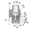
次に、本発明の第三および第四の部品収納ボックスとして好適な一実施形態を図面を参照しつつ説明する。なお、本実施形態において、後述する封止部78およびカバー固定部75に関するもの以外の構成はいずれも上記実施形態と同様であるので、以下に説明する図12〜図15は、後述する封止部およびカバー固定部の要部のみを示している。本実施形態に係る部品収納ボックスも上述の本基板収納ボックス10と同様の筐体本体部とカバーとからその外形が構成されており、その内部には回路基板等の電気部品が装填されている。而して、図13に示すように、筐体本体部とカバー(図示せず)の端部には上記実施形態と同様のカバー固定部75と封止部78とが形成されており、連結片75b,78bを介して締着部75aおよびビス取付部78aが設けられている。而して、図13に示すように、上記実施形態と同様、締着部75aならびにビス取付部78aには、それぞれ、円形中空状の締着材貫通部分75dと方形中空状の締着材かしめ部分75e、ならびに円形中空状の締着材装着部分78cと円形中空状の締着材貫通部分78dが形成されている。なお、図13に示すように、本実施形態において、ビス取付部78aの底面は凸状に突出しており、対応する締着部75aの上面は凹状に窪んでいる。このため、これら凹凸を嵌合させることでカバー固定部75と封止部78との位置決めが容易となる。
【0033】
次に、本実施形態に係る締め付けネジ85と抜け止めナット具80について説明する。先ず、締め付けネジ85について説明する。図13に示すように、本実施形態に係る締め付けネジ85は、大径の逆円錐状の頭部85aとそれより小径の軸部85bとから構成されている。この軸部85bはさらに、頭部85a寄りのねじの形成されていない基幹部85cと、雄ねじの形成された先端部85fと、当該基幹部85cと先端部85fとの間に形成されるやや直径の小さい中間部85eとから構成されている。すなわち、本実施形態においては、本発明の第四の部品収納ボックスに係る上記中央部は基幹部85cと中間部85eとから構成される。また、基幹部85cの所望する一部には、凹部85dが全周に亘って形成されている(図13)。なお、各部位のサイズ(直径)は、基幹部85cが最も太く、次いで、先端部85f、中間部85e、凹部85dの順に細くなる。また、中間部85eは、後述するボス81のねじ形成部分81bよりも長くなるように形成されている。
【0034】
本実施形態に係る抜け止めナット具80は、図13に示すように、締着部75aの締着材かしめ部分75eに嵌装されるボス81と当該ボス81と締着部75aとの間に挟み込まれる係止ナット部材82とから構成されている。図12に示すように、この係止ナット部材82は、締着材かしめ部分75eに丁度収容し得るサイズのうすい方形プレート状に形成されており、その中央には締め付けネジ85を通常では貫通させ得ない程度の比較的小さな貫通孔82aが形成されている。而して、その周囲にはスリットを設けたことによって一方の面にやや折り曲げられた係止片82bが形成されている。このことによって、後述するように、締め付けネジ85は当該折り曲げ方向に強く押されたときに限り上記貫通孔82aを不可逆的に通ることが可能となる。
【0035】
一方、抜け止めナット具80を構成するボス81はその一部が締着材かしめ部分75eに丁度嵌装し得るサイズに形成された角柱状の部材であり、その中心部には上記締め付けネジ85の軸部85bを貫通させるための中空部が形成されている。図13に示すように、この中空部は、内径の異なる3部分から構成されている。すなわち、図13における上部から順にいうと、締め付けネジ85の上記先端部85fおよび中間部85eは通過可能だが基幹部85cは入り込めない係止部分81a、上記先端部85fにおける雄ねじに対応した雌ねじの形成されたねじ形成部分81bおよび当該ねじ形成部分81bを貫通した締め付けネジ85先端部85fに接触し得ない程度に内径が広く確保されている非接触部分81cである。なお、非接触部分81c下方の開口部は、開放したままでもよいし上記実施形態におけるような遮蔽板で遮蔽してもよい。
【0036】
次に、上記締め付けネジ85および抜け止めナット具80を用いて、本実施形態に係る部品収納ボックスにおいてのカバーの筐体本体部に対する固定方法を詳述する。図13に示すように、先ず、カバー固定部75締着部75aにおける締着材かしめ部分75eに抜け止めナット具80を圧入する。すなわち、上記係止ナット部材82を挟み込むようにしてボス81の一部を締着材かしめ部分75eに嵌装する。このとき、締め付けネジの締着方向と係止ナット部材82の係止片82b折り曲げ方向が同調するようにして係止ナット部材82を挟み込むことが重要である。次いで、図13に示すように、封止部78ビス取付部78aにおける締着材装着部分78cから挿入した締め付けネジ85をそのまま押し込み、図14に示すように、締め付けネジ85の先端部85fとボス81のネジ形成部分81bとを螺合させ、そのまま締め込む。このとき、締め付けネジ85の先端部85fとボス81ねじ形成部分81bとの螺合によって結果的にボス81は上方に引き上げられることとなり、その締結力によってボス81は強く締着材かしめ部分75eに圧入されることとなる。同時にその締結力を利用して締め付けネジ85の軸部85bは係止ナット部材82貫通孔82aを係止片82bを押し広げるようにして通ることが可能となる。而して、図15に示すように、締め付けネジ85の先端部とボス81のねじ形成部分81bとの螺合が終了して、当該締め付けネジ85の先端部85fが上記非接触部分81cにまで至ったとき、上記係止ナット部材82の係止片82bを締め付けネジ85の上記凹部85dに填り込ませるようにしてある。
【0037】
このような構成とした結果、もはや締め付けネジ85の引き抜きは不能となる。すなわち、締め付けネジ85を挿入方向とは逆方向に引き抜こうとした場合、上記凹部85dに填り込んだ上記係止ナット部材82の係止片82bが凹部82dより下方にある基幹部85cに係合してしまい、結果、当該締め付けネジ85の引き抜きが当該係合によって阻まれるからである。また、本実施形態においては、図15に示すように、締着部75aとビス取付部78aとの締結完了後は、もはや締め付けネジ85の先端部85fは、いずれにも螺合しておらず、当該ネジ85を弛め方向に回しても空回りするばかりで引き抜かれるおそれはない。従って、本実施形態に係る部品収納ボックスによっても、上述の各実施形態に係る基板収納ボックス10,50と同様、カバーの不正な再開放を防ぎ、ボックス内部の封止状態(密閉状態)を保つことが可能となる。
【0038】
以上、部品収納ボックスの好適ないくつかの実施形態を図面を参照しつつ説明したが、部品収納ボックスは、上述の各実施形態に限定されない。例えば、第一あるいは第二の部品収納ボックスとしての上述の実施形態は、いずれも中空部に雌ねじを形成するナット具形状のものをかしめ部材30,60としているが、第一の部品収納ボックスにおいては、上記筐体本体部とカバーとを貫通した状態で締着されたかしめ部材の先端部分がその貫通した位置において外方に広がることによってかしめが完了していればよく、上記ナット具形状のものに限定されない。例えば、雌ねじの形成されていない中空を有するいわゆるブラインドリベット形状のかしめ部材によって上記筐体本体部とカバーとを貫通させ、その状態で釘状の締着材を当該中空に押し込んだり或いは引っ張ったりして当該ブラインドリベット形状かしめ部材の貫通した先端部を外方に広げてかしめるものでもよい。なお、上述の実施形態では、筐体本体部とカバーとから側方に張り出した状態で上記カバー固定部25,55および封止部28,58が設けられているが、このような形状は内部検査等の目的のために再開放を意図した付加的なものにすぎず、カバーと筐体本体部とを上記かしめ部材によって封止する部位はなんら限定されない。
【0039】
また、本発明の第三あるいは第四の部品収納ボックスとしての上述の実施形態は、上記締め付けネジ85として、雄ねじの形成された先端ねじ部と雄ねじの形成されていない中央部(即ち上述の基幹部85cおよび中間部85e)とを有するものを使用したが、本発明における上記締め付けネジは、上記抜け止めナット具に装備された係止ナット部材との係合によって、上記筐体本体部とカバーとを貫通した状態で装着された際に引き抜きが阻止され得るものであればよく、例えば上記中間部85eに雄ねじの形成されたものであってもよい。また、上記実施形態では、抜け止めナット具を構成するボスと係止ナット部材とが別体で構成されているが、これに限定されず、ボスと係止ナット部材とが一体に構成されたものでもよい。このような変更例は本発明の実施の一例であり、本明細書および図面に開示された情報に基づく当業者の設計事項にすぎないものであり、本願特許請求の範囲から逸脱するものではない。
【0040】
【発明の効果】
本発明によれば、遊技機に装着される部品収納ボックスであって、防犯上の観点から当該ボックス内部が一旦封止(密閉)された後には外部から不正に再開放されないように封止(密閉)された遊技機用部品ボックスが提供される。
【0041】
【0042】
また、本発明の第三および第四の部品収納ボックスでは、上記かしめ部材に代えて締め付けネジと抜け止めナット具との係合によって筐体本体部にカバーを固定するとともに、当該抜け止めナット具に備えられた係止ナット部材によって上記貫通状態の締め付けネジの引き抜きを防止しており、上記締め付けネジの引き抜きに基づく上記筐体本体部とカバーとの再開放を防止することができる。従って、本発明の第三および第四の部品収納ボックスによれば、当該再開放による不正行為の発生を未然に防止することができる。
【図面の簡単な説明】
【図1】 一実施形態に係る部品収納ボックスを装備した弾球遊技機の背面図である。
【図2】 一実施形態に係る部品収納ボックスを示した正面図である。
【図3】 図2におけるIII −III 線矢視断面図である。
【図4】 一実施形態に係る部品収納ボックスの要部を示す一部破断の斜視図である。
【図5】 一実施形態に係る部品収納ボックスの要部を示す一部破断の斜視図である。
【図6】 一実施形態に係る部品収納ボックスにおけるかしめ部材の締着状況を説明する断面図であり、(A)はかしめ部材を仮圧入した状態、(B)はかしめ部材を押し込んだ状態、(C)はかしめ部材をかしめた状態、および(D)はかしめ完了後に塞ぎプラグを装着した状態を示す。
【図7】 一実施形態に係る塞ぎプラグの外観を示す斜視図である。
【図8】 一実施形態に係る部品収納ボックスにおいてかしめ部材を装着した状態を説明する断面図である。
【図9】 一実施形態に係る部品収納ボックスにおいてかしめ部材に締着材を締め込んでいる状態を説明する断面図である。
【図10】 一実施形態に係る部品収納ボックスにおいてかしめ部材に締着材を締め込んでいる状態を説明する断面図である。
【図11】 一実施形態に係る部品収納ボックスにおいてかしめ部材に締着材を締め込んでかしめを完了した状態を説明する断面図である。
【図12】 一実施形態に係る部品収納ボックスに使用される係止ナット部材の外観を示す斜視図である。
【図13】 一実施形態に係る本発明の部品収納ボックスにおける締め付けネジおよび抜け止めナット具の装着状況を説明する断面図である。
【図14】 一実施形態に係る本発明の部品収納ボックスにおける締め付けネジを抜け止めナット具に締め込んでいる状態を説明する断面図である。
【図15】 一実施形態に係る本発明の部品収納ボックスにおける締め付けネジと抜け止めナット具の係止ナット部材との係合状況を説明する断面図である。
【図16】 従来の基板収納ボックスにおける封止手段を模式的に説明する断面図である。
【図17】 従来の塞ぎプラグの外観を示す斜視図である。
【符号の説明】
1 弾球遊技機
6 遊技盤
10,50,100 基板収納ボックス
12,52,102 カバー
13,53 回路基板
14,54,101 筐体本体部
25,55,75 カバー固定部
25a,55a,75a 締着部
25b,55b,75b 連結片
28,58,78 封止部
28a,58a,78a ビス取付部
28b,58b,78b 連結片
30,60 かしめ部材
35,65 かしめ用ビス
80 抜け止めナット具
81 ボス
82 係止ナット部材
85 締め付けネジ[0001]
BACKGROUND OF THE INVENTION
The present invention relates to a component storage box for a gaming machine used to store an electrical component (such as a board) and other components mounted on a gaming machine, and more particularly to a sealing means for the component storage box.
[0002]
[Prior art]
There are many electric parts and delicately structured parts (such as slot machines and card game machines) in ball game machines and other stationary game machines (slot machines, card game machines, etc.) that are used in so-called pachinko games. It is equipped with a prize ball payout device etc. in a ball game machine). Among these components, for example, a circuit board constructed to electrically control the operation of various gaming devices is usually a predetermined storage box (housing) from the viewpoint of dustproofness and assembly workability. It is arranged in the gaming machine in a state of being housed in the game machine.
[0003]
By the way, as a serious fraudulent act against a gaming machine, a box for storing a circuit board (hereinafter referred to as a “board storage box”) is opened and electric parts such as an internal ROM are replaced, or a board storage box (circuit board). There is an act of connecting to another illegal board from the wiring pattern of the connector attached to the connector. As a measure for preventing such an illegal act, typically, as shown in FIG. 16, a
[0004]
[Problems to be solved by the invention]
However, it has been difficult to completely prevent an illegal act of an unauthorized player even by the sealing means of the
[0005]
The present invention solves the problems associated with the conventional sealing means in the above-mentioned board storage box and other parts storage boxes for gaming machines, and the purpose of the present invention is to temporarily store the inside of the box from the viewpoint of crime prevention. After sealing (sealing), there is provided a sealing means for the cover and the housing main body that prevents unauthorized reopening from the outside, and a gaming machine parts box sealed by such sealing means. Is to provide.
[0006]
[Means for Solving the Problems]
[0007]
[0008]
[0009]
[0010]
Up In order to achieve the above-mentioned object, the present invention is a box for storing a part to be mounted on a gaming machine, and a casing main body part for storing the part of the gaming machine, and shielding the stored part from the outside. And a cover that covers the casing main body, and the cover is disposed on the penetrating side of the tightening screw and the tightening screw that is mounted in a state of penetrating the casing main body and the cover. It is fixed to the housing main body by engaging with the retaining nut tool, and the retaining nut tool is locked to prevent the tightening screw mounted in the penetrating state from being pulled out. A component housing for a gaming machine that is provided with a nut member, and that a part of the tightening screw engages with the locking nut member to maintain the fixed state of the cover with respect to the housing body. Box (hereinafter referred to as "third component storage box of the present invention".) Provides.
[0011]
In the third component storage box of the present invention, the cover is fixed to the housing main body by engagement of the tightening screw and the retaining nut tool instead of the caulking member, and the retaining nut tool is provided. The lock nut member prevents the tightening screw in the penetrating state from being pulled out. Thereby, in the third component storage box of the present invention, , Housing It is possible to maintain a fixed state of the cover fixed to the casing main body with respect to the casing main body so as to shield the part loading portion of the body main body from the outside. For this reason, the third component storage box of the present invention also prevents reopening of the housing body and the cover based on the pulling out of the tightening screw, and prevents the occurrence of fraud by the reopening. it can.
[0012]
In the present invention, the third component storage box of the present invention described above is further preferred, and the shaft portion of the tightening screw includes a tip screw portion on which a male screw is formed and a central portion on which no screw is formed. A female screw corresponding to the male screw is formed in the hollow portion of the retaining nut member, wherein the tightening screw and the retaining nut member are the same as the tightening screw. When the screw is completely tightened, the tip screw portion of the tightening screw penetrates through the hollow portion of the retaining nut tool and does not engage with the locking nut member. A gaming machine component storage box (hereinafter referred to as “a”) that is provided so as to engage with a part of the central portion of the tightening screw when the screw is completely tightened with respect to the retaining nut member. That the fourth parts storage box "of the invention.) To provide.
[0013]
In the fourth component storage box of the present invention, in the state in which the cover is fixed to the housing body (that is, the state in which the tightening screw is completely tightened with respect to the retaining nut member), And screwing (screw fitting) with the retaining nut tool are released, and the tip portion penetrates to the opposite side of the retaining nut tool. For this reason, in the fourth component storage box of the present invention, even if an unauthorized player can successfully rotate the tightening screw in the loosening direction in a state of being completely tightened against the retaining nut device. Even so, as a result of the tightening screw not being screwed onto the retaining nut tool, the tightening screw only turns idle at that position. Further, at this time, since the tightening screw engages with the locking nut member at the central portion of the tightening screw, it is possible to prevent the tightening screw from moving in the pulling direction. Therefore, according to the fourth component storage box of the present invention, the reopening of the housing body and the cover based on the pulling out of the tightening screw can be more effectively prevented, and the occurrence of fraud by the reopening. Can be prevented in advance.
[0014]
DETAILED DESCRIPTION OF THE INVENTION
Hereinafter, the parts storage box of the present invention (upper) installed in a ball game machine (pachinko machine) which is a typical example of a game machine. No. Includes third and fourth parts storage boxes. same as below. ) Will be described with reference to the drawings. First, the present invention It has almost the same configuration as the configuration of the third and fourth parts storage boxes. An embodiment suitable as the first and second component storage boxes will be described. FIG. 1 relates to this embodiment. Part 2 is a rear view showing a rear surface configuration of a ball game machine 1 equipped with an
[0015]
A bullet ball game machine 1 according to the present embodiment includes a base frame and a metal frame (both not shown) formed in a frame shape on the front surface of a wooden frame 3 formed in a rectangular frame shape, and a game is provided on the inside thereof. This is a normal type ball and ball game machine 1 provided with a board surface (that is, a game area in which nails, windmills, etc. are appropriately arranged). As shown in FIG. 1, a game ball launching device 8 and a
[0016]
On the other hand, a
[0017]
FIG. 2 is a front view showing the outer shape of the
[0018]
Next, the
[0019]
Next, a means for fixing the
[0020]
Next, the shape of each structural member related to the
[0021]
Next, the structure of the
[0022]
Thus, a
[0023]
Next, a method for fixing the
[0024]
Next, as shown in FIG. 4 and FIG. 6B, the
Thereby, the caulking of the
[0025]
As described above, the sealing
[0026]
As described above, the
[0027]
more than The second Although a preferred embodiment has been described as the first and second component storage boxes, Embodiment In carrying out the above, the
[0028]
Next, the
[0029]
Thus, the
[0030]
Next, a method for fixing the
[0031]
Next, as shown in FIG. 9, the
[0032]
Next, an embodiment suitable as the third and fourth component storage boxes of the present invention will be described with reference to the drawings. In addition, in this embodiment, since structures other than those related to the sealing
[0033]
Next, the tightening
[0034]
As shown in FIG. 13, the retaining
[0035]
On the other hand, a part of the
[0036]
Next, a method for fixing the cover to the housing body in the component storage box according to the present embodiment will be described in detail using the tightening
[0037]
As a result of such a configuration, the clamping
[0038]
more than , Department Although several preferred embodiments of the item storage box have been described with reference to the drawings, , Department The product storage box is not limited to the above-described embodiments. For example The second In the above-described embodiments as the first or second component storage box, the
[0039]
Further, in the above-described embodiment as the third or fourth component storage box of the present invention, as the
[0040]
【The invention's effect】
According to the present invention, a component storage box mounted on a gaming machine is sealed so that it is not reopened from the outside after the inside of the box is once sealed (sealed) from the viewpoint of crime prevention. A hermetically sealed gaming machine parts box is provided.
[0041]
[0042]
Further, in the third and fourth parts storage boxes of the present invention, the cover is fixed to the housing body by engagement of a tightening screw and a retaining nut tool instead of the caulking member, and the retaining nut tool The locking nut member provided in the connector prevents the tightening screw in the penetrating state from being pulled out, and reopening of the housing body and the cover based on the pulling out of the tightening screw can be prevented. Therefore, according to the third and fourth parts storage boxes of the present invention. This It is possible to prevent an illegal act from occurring due to the reopening.
[Brief description of the drawings]
FIG. 1 relates to an embodiment. Part It is a rear view of the ball game machine equipped with the goods storage box.
FIG. 2 relates to an embodiment Part It is the front view which showed the goods storage box.
3 is a cross-sectional view taken along line III-III in FIG.
FIG. 4 is related to one embodiment Part It is a partially broken perspective view which shows the principal part of a goods storage box.
FIG. 5 relates to an embodiment Part It is a partially broken perspective view which shows the principal part of a goods storage box.
FIG. 6 relates to an embodiment Part It is sectional drawing explaining the fastening condition of the caulking member in an article storage box, (A) is a state in which the caulking member is temporarily press-fitted, (B) is a state in which the caulking member is pushed in, and (C) is caulking the caulking member. The state and (D) show the state where the plug is attached after the caulking is completed.
FIG. 7 is a perspective view showing an appearance of a closing plug according to an embodiment.
FIG. 8 relates to one embodiment Part It is sectional drawing explaining the state which attached the crimping member in the goods storage box.
FIG. 9 relates to one embodiment Part It is sectional drawing explaining the state which fastened the fastening material to the crimping member in the goods storage box.
FIG. 10 relates to one embodiment. Part It is sectional drawing explaining the state which fastened the fastening material to the crimping member in the goods storage box.
FIG. 11 relates to an embodiment. Part It is sectional drawing explaining the state which tightened the fastening material to the crimping member in the goods storage box, and completed crimping.
FIG. 12 relates to one embodiment Part It is a perspective view which shows the external appearance of the latching nut member used for a goods storage box.
FIG. 13 is a cross-sectional view illustrating a mounting state of a tightening screw and a retaining nut tool in the component storage box of the present invention according to one embodiment.
FIG. 14 is a cross-sectional view illustrating a state in which a tightening screw is tightened into a retaining nut tool in the component storage box of the present invention according to one embodiment.
FIG. 15 is a cross-sectional view illustrating an engagement state between a tightening screw and a locking nut member of a retaining nut tool in the component storage box of the present invention according to one embodiment.
FIG. 16 is a cross-sectional view schematically illustrating sealing means in a conventional substrate storage box.
FIG. 17 is a perspective view showing the appearance of a conventional plug.
[Explanation of symbols]
1 Ball game machine
6 Game board
10, 50, 100 Substrate storage box
12, 52, 102 cover
13,53 Circuit board
14, 54, 101 Case body
25, 55, 75 Cover fixing part
25a, 55a, 75a Fastening part
25b, 55b, 75b connecting piece
28, 58, 78 Sealing part
28a, 58a, 78a Screw mounting part
28b, 58b, 78b Connecting piece
30, 60 Caulking member
35,65 Screws for caulking
80 Retaining nut device
81 boss
82 Locking nut member
85 Tightening screw
Claims (2)
遊技機の部品を収納する筐体本体部と、該収納された部品を外部から遮蔽するようにして該筐体本体部に被せられるカバーとを備えており、
そのカバーは、該筐体本体部と該カバーとを貫通した状態で装着された締め付けネジと該締め付けネジ先端の貫通した側に配置された抜け止めナット具との係合によって該筐体本体部に固定されており、
ここで該抜け止めナット具には、該貫通状態で装着された締め付けネジの引き抜きを阻止するための係止ナット部材が備えられており、その係止ナット部材に該締め付けネジの一部が係合することによって該筐体本体部に対する該カバーの固定状態の維持が実現される遊技機用部品収納ボックス。A box for storing parts to be mounted on a gaming machine,
A housing body for storing the parts of the gaming machine, and a cover that covers the housing body so as to shield the housed components from the outside,
The cover is formed by engagement of a tightening screw mounted in a state of penetrating the housing main body and the cover, and a retaining nut member disposed on a penetrating side of the tip of the tightening screw. Is fixed to
Here, the retaining nut member is provided with a locking nut member for preventing the tightening screw mounted in the penetrating state from being pulled out, and a part of the tightening screw is engaged with the locking nut member. A component storage box for a gaming machine that can maintain a fixed state of the cover with respect to the housing main body by being combined.
ここで、該締め付けネジと該抜け止めナット具とは、該締め付けネジが該抜け止めナット具に対して完全に締め込まれたときに該締め付けネジの先端ねじ部が該抜け止めナット具の中空部を突き抜けて螺合しないように構成されており、かつ、前記係止ナット部材は該締め付けネジが該抜け止めナット具に対して完全に締め込まれたときに該締め付けネジ中央部の一部と係合するように設けられている請求項1に記載の遊技機用部品収納ボックス。The shaft portion of the tightening screw has a tip screw portion in which a male screw is formed and a central portion in which no screw is formed, and a female screw corresponding to the male screw is formed in the hollow portion of the retaining nut tool. Has been
Here, the tightening screw and the retaining nut tool are such that when the tightening screw is completely tightened with respect to the retaining nut tool, the tip screw portion of the tightening screw is hollow in the retaining nut tool. And the locking nut member is a part of the central portion of the tightening screw when the tightening screw is completely tightened against the retaining nut member. The game machine component storage box according to claim 1 , wherein the game machine component storage box is provided to engage with the game machine.
Priority Applications (1)
| Application Number | Priority Date | Filing Date | Title |
|---|---|---|---|
| JP08695098A JP4092420B2 (en) | 1998-03-31 | 1998-03-31 | Parts storage box for gaming machines |
Applications Claiming Priority (1)
| Application Number | Priority Date | Filing Date | Title |
|---|---|---|---|
| JP08695098A JP4092420B2 (en) | 1998-03-31 | 1998-03-31 | Parts storage box for gaming machines |
Publications (2)
| Publication Number | Publication Date |
|---|---|
| JPH11276695A JPH11276695A (en) | 1999-10-12 |
| JP4092420B2 true JP4092420B2 (en) | 2008-05-28 |
Family
ID=13901162
Family Applications (1)
| Application Number | Title | Priority Date | Filing Date |
|---|---|---|---|
| JP08695098A Expired - Lifetime JP4092420B2 (en) | 1998-03-31 | 1998-03-31 | Parts storage box for gaming machines |
Country Status (1)
| Country | Link |
|---|---|
| JP (1) | JP4092420B2 (en) |
Cited By (1)
| Publication number | Priority date | Publication date | Assignee | Title |
|---|---|---|---|---|
| JPH07223432A (en) * | 1994-02-07 | 1995-08-22 | Toyo Seimitsu Kogyo Kk | Defrosting screen serving also as awning for automobile |
Families Citing this family (20)
| Publication number | Priority date | Publication date | Assignee | Title |
|---|---|---|---|---|
| JP3531807B2 (en) * | 2000-07-27 | 2004-05-31 | 株式会社サンセイアールアンドディ | Game machine |
| JP4696349B2 (en) * | 2000-10-10 | 2011-06-08 | 株式会社竹屋 | Game machine board case |
| JP5099294B2 (en) * | 2006-02-15 | 2012-12-19 | 株式会社三洋物産 | Game machine |
| JP5099293B2 (en) * | 2006-02-15 | 2012-12-19 | 株式会社三洋物産 | Game machine |
| JP5099292B2 (en) * | 2006-02-15 | 2012-12-19 | 株式会社三洋物産 | Game machine |
| JP5194757B2 (en) * | 2007-11-21 | 2013-05-08 | 株式会社三洋物産 | Game machine |
| JP4653185B2 (en) * | 2008-01-25 | 2011-03-16 | 株式会社ソフイア | Game machine |
| JP5172413B2 (en) * | 2008-03-25 | 2013-03-27 | 株式会社ニューギン | Board case for gaming machines |
| JP5090226B2 (en) * | 2008-03-25 | 2012-12-05 | 株式会社ニューギン | Board case for gaming machines |
| JP5110653B2 (en) * | 2008-07-18 | 2012-12-26 | 豊丸産業株式会社 | Control device and game machine |
| JP5194216B2 (en) * | 2008-07-18 | 2013-05-08 | 豊丸産業株式会社 | Control device and game machine |
| JP2010110474A (en) * | 2008-11-06 | 2010-05-20 | Kyoraku Sangyo Kk | Game machine |
| JP5422715B2 (en) * | 2012-09-12 | 2014-02-19 | 株式会社ニューギン | Board case for gaming machines |
| JP5435604B2 (en) * | 2012-10-15 | 2014-03-05 | 豊丸産業株式会社 | Control device and game machine |
| JP5766325B2 (en) * | 2014-04-01 | 2015-08-19 | 株式会社ユニバーサルエンターテインメント | Game machine |
| JP2019041891A (en) * | 2017-08-30 | 2019-03-22 | 株式会社ユニバーサルエンターテインメント | Game machine |
| JP2019041889A (en) * | 2017-08-30 | 2019-03-22 | 株式会社ユニバーサルエンターテインメント | Game machine |
| JP2019041890A (en) * | 2017-08-30 | 2019-03-22 | 株式会社ユニバーサルエンターテインメント | Game machine |
| JP2019041892A (en) * | 2017-08-30 | 2019-03-22 | 株式会社ユニバーサルエンターテインメント | Game machine |
| JP2019041893A (en) * | 2017-08-30 | 2019-03-22 | 株式会社ユニバーサルエンターテインメント | Game machine |
-
1998
- 1998-03-31 JP JP08695098A patent/JP4092420B2/en not_active Expired - Lifetime
Cited By (1)
| Publication number | Priority date | Publication date | Assignee | Title |
|---|---|---|---|---|
| JPH07223432A (en) * | 1994-02-07 | 1995-08-22 | Toyo Seimitsu Kogyo Kk | Defrosting screen serving also as awning for automobile |
Also Published As
| Publication number | Publication date |
|---|---|
| JPH11276695A (en) | 1999-10-12 |
Similar Documents
| Publication | Publication Date | Title |
|---|---|---|
| JP4092420B2 (en) | Parts storage box for gaming machines | |
| JP4117296B2 (en) | Board case for gaming machines | |
| JP4125546B2 (en) | Mechanism for preventing unauthorized opening of circuit board case | |
| JP3630362B2 (en) | Substrate case sealing structure | |
| JPH11104327A (en) | Board housing case in game machine | |
| JP2004065791A (en) | Circuit board case | |
| JP2000254320A5 (en) | ||
| JP5058590B2 (en) | Board case for gaming machine and gaming machine | |
| JP2001113007A (en) | Sealing case for control circuit device | |
| JP2000189633A (en) | Substrate box for game machine | |
| JP5002764B2 (en) | Game machine | |
| JPH09201449A (en) | Box for storing circuit board in game machine | |
| JP2952205B2 (en) | Circuit board mounting structure for gaming machines | |
| JP6780721B2 (en) | Game machine | |
| JP4453133B2 (en) | Game machine | |
| JPH11179031A (en) | Connection body for iniquity prevention | |
| JP3701438B2 (en) | Base case for gaming machines | |
| JPH11226220A (en) | Circuit board case for game machine | |
| JP4057623B2 (en) | Board storage box for gaming machines | |
| JP3862451B2 (en) | Board case for gaming machines | |
| JP4057622B2 (en) | Board storage box for gaming machines | |
| JP4057606B2 (en) | Board storage box for gaming machines | |
| JP6501730B2 (en) | Substrate case for gaming machines | |
| JPH09239096A (en) | Base board containing box of game machine | |
| JP2001259201A (en) | Substrate box for game machine |
Legal Events
| Date | Code | Title | Description |
|---|---|---|---|
| A621 | Written request for application examination |
Free format text: JAPANESE INTERMEDIATE CODE: A621 Effective date: 20050322 |
|
| A131 | Notification of reasons for refusal |
Free format text: JAPANESE INTERMEDIATE CODE: A131 Effective date: 20071030 |
|
| A521 | Written amendment |
Free format text: JAPANESE INTERMEDIATE CODE: A523 Effective date: 20071227 |
|
| TRDD | Decision of grant or rejection written | ||
| A01 | Written decision to grant a patent or to grant a registration (utility model) |
Free format text: JAPANESE INTERMEDIATE CODE: A01 Effective date: 20080205 |
|
| A61 | First payment of annual fees (during grant procedure) |
Free format text: JAPANESE INTERMEDIATE CODE: A61 Effective date: 20080214 |
|
| FPAY | Renewal fee payment (event date is renewal date of database) |
Free format text: PAYMENT UNTIL: 20110314 Year of fee payment: 3 |
|
| R150 | Certificate of patent or registration of utility model |
Free format text: JAPANESE INTERMEDIATE CODE: R150 |
|
| FPAY | Renewal fee payment (event date is renewal date of database) |
Free format text: PAYMENT UNTIL: 20140314 Year of fee payment: 6 |
|
| S531 | Written request for registration of change of domicile |
Free format text: JAPANESE INTERMEDIATE CODE: R313531 |
|
| FPAY | Renewal fee payment (event date is renewal date of database) |
Free format text: PAYMENT UNTIL: 20140314 Year of fee payment: 6 |
|
| R350 | Written notification of registration of transfer |
Free format text: JAPANESE INTERMEDIATE CODE: R350 |
|
| R250 | Receipt of annual fees |
Free format text: JAPANESE INTERMEDIATE CODE: R250 |
|
| R250 | Receipt of annual fees |
Free format text: JAPANESE INTERMEDIATE CODE: R250 |
|
| R250 | Receipt of annual fees |
Free format text: JAPANESE INTERMEDIATE CODE: R250 |
|
| EXPY | Cancellation because of completion of term |