JP4125546B2 - Mechanism for preventing unauthorized opening of circuit board case - Google Patents
Mechanism for preventing unauthorized opening of circuit board case Download PDFInfo
- Publication number
- JP4125546B2 JP4125546B2 JP2002152997A JP2002152997A JP4125546B2 JP 4125546 B2 JP4125546 B2 JP 4125546B2 JP 2002152997 A JP2002152997 A JP 2002152997A JP 2002152997 A JP2002152997 A JP 2002152997A JP 4125546 B2 JP4125546 B2 JP 4125546B2
- Authority
- JP
- Japan
- Prior art keywords
- insertion hole
- case
- screw
- lid member
- case lid
- Prior art date
- Legal status (The legal status is an assumption and is not a legal conclusion. Google has not performed a legal analysis and makes no representation as to the accuracy of the status listed.)
- Expired - Fee Related
Links
Images


Description
【0001】
【発明の属する技術分野】
本発明は、パチンコ機やスロットマシン等の遊技機において遊技機の作動を制御する制御基板等を収容する基板ケースに関し、詳細には基板を収容した状態の基板ケースを不正に開放できなくして基板に対する不正行為を防止する基板ケースの不正開放防止機構に関する。
【0002】
【従来の技術】
パチンコ機やスロットマシン等の遊技機では遊技機の作動を制御する制御基板が設けられている。例えばパチンコ遊技機では外枠に対して開閉可能に組み付けられた前枠裏側の収容枠に遊技盤及び裏機構盤が開閉可能に装備され、この裏機構盤に制御基板が取り付けられている。また、スロットマシンにおいても同様に、開閉カバーの裏面に制御基板が取り付けられている。これら制御基板は賞球もしくはメダルの払出制御、電動役物の開閉制御、リールの回転制御、図柄組み合わせの発生確率制御など、パチンコ遊技機もしくはスロットマシンの作動を制御する基板であり、遊技機の制御ソフトウェアが記録されたROMが搭載されて遊技機の作動を制御する中枢制御装置としての役割を有している。このため、制御基板は偽造ROMへの差し替え等の不正改造を受け難いように基板ケース内に収容されるとともに、この基板ケースはケースを開いたときにその痕跡が残るような不正開放(もしくは不正改造)防止手段が設けられて構成されている。
【0003】
このような不正開放防止手段として、例えば、切断可能な複数のネジ締結対を特殊ネジで締結する手段がある。これは、ケース本体部材とこのケース本体部材に開閉自在に装着されるケース蓋部材とからなる基板ケースにおいて、ケース本体部材及びケース蓋部材のそれぞれの側縁部に相対応するネジ螺合部及びネジ貫通部からなるネジ締結対を複数対形成し、このうち少なくとも1対のネジ螺合部とネジ貫通部とを締め込み方向にのみ操作可能な特殊ネジ(ネジ頭部のスリ割りがネジ締め方向のみに係合部を有して形成され、緩める方向の係合部が螺旋状に除去されているネジ、以下本明細書で「一方向ネジ」という)で締結する構成からなっている。なお、この構成において、ケース蓋部材とネジ貫通部との間には切断可能な切断部が形成されている。
【0004】
上記の不正開放防止手段では、管理者が制御基板の保守点検等のために基板ケースを開くときには、一方向ネジで締結された締結対の切断部をニッパ等の工具で切断し、ネジ貫通部をケース蓋部材から切り離すことでケース蓋部材とケース本体部材との接続を解除してケース蓋部材を開放する。このようにケース蓋部材を開放して保守点検が行われるが、この保守点検完了後には未だ締結していない他の締結対を一方向ネジを用いて締結しケース本体部材にケース蓋部材を装着・閉鎖する。さらに、基板ケースには基板管理番号と開封履歴を表示する基板管理シールが貼られており、開封した管理者がこの基板管理シールに開封年月日と開封者氏名を記載して管理するようになっている。
【0005】
【発明が解決しようとする課題】
上記のような不正開放防止手段によれば、一方向ネジは一般にネジを緩める方向に回転させることができず、基板ケースを開く時には切断部を切り離す必要があることから、基板ケース開放後にその切断痕跡が明確に残り、不正な開封が不可能のように思われる。ところが、このような不正改造防止手段をもってしても、これを迂回する巧妙な不正改造行為が散発的に発見されており、かかる手段のみでは未だ完全を期しがたいことが指摘されるようになっている。
【0006】
例えば、不正者が特殊な手段を用いて一方向ネジに損傷を与えることなく取り外し、不正改造後に取り外した一方向ネジを元の位置に締結し直すことで、一見しただけでは不正行為を見抜き難いような改造工作を行った例が発見されており、このようなケースが徐々に拡散するようになってきたのである。このことは不正な改造行為を未然に防止するという基板ケースの本質的機能を損なう重大な問題であり、早期改善が望まれていた。
【0007】
また、上記のように保守点検の度に締結対の切断部を切断してケースを開放する構成では、締結対の数に対応する回数の保守点検が可能でしかなく、これ以上の回数の保守点検に対してはケース全体の交換が必要になるなど、対応が難しいという問題がある。
【0008】
本発明は、上記問題に鑑みて成さたものであり、保守点検等のためのケースの開放は何度でも行うことができるが、不正開放を行ったときにはこれを容易に発見できるようにして不正開放を効果的に防止できるような構成の不正開放防止機構を提供し、公正な遊技に供することができる遊技機の基板ケースを提供することを目的とする。
【0009】
【課題を解決するための手段】
上記目的達成のため、本発明では、遊技機に取り付けられるケース本体部材と、ケース本体部材に装着されるケース蓋部材とを備え、ケース本体部材にケース蓋部材を装着して形成されるケース内部に制御基板を収容する基板ケースにおいて、その不正開放防止機構が、ケース本体部材にケース蓋部材を取り付けた状態でケース本体部材とケース蓋部材を一体結合するための結合ネジと、ケース蓋部材の外面から円筒状に窪んでケース蓋部材に形成され、ケース蓋部材をケース本体に結合させるために結合ネジを挿入する挿入孔と、この挿入孔を覆ってケース蓋部材に取り付けられる遮蔽部材とを備えて構成される。そして、挿入孔が、入口部に位置して遮蔽部材が装着される入口側挿入孔と、入口側挿入孔より小径で孔底面からケース蓋部材の内側に貫通して形成されたネジ挿入貫通孔とから形成され、ケース本体部材にケース蓋部材を取り付けた状態で、ケース本体部材におけるネジ貫通挿入孔と対向する部分に、結合ネジと螺合するネジ孔が形成されており、挿入孔に結合ネジを挿入し、そのネジ部をネジ貫通挿入孔を通してネジ孔に螺合させて結合ネジによりケース蓋部材をケース本体に結合させた後、遮蔽部材を入口側挿入孔に取り付けて結合ネジの結合解除操作を阻止するように構成されており、ここで、遮蔽部材は入口側挿入孔に一旦取り付けた後においては外部からはケース蓋部材から取り外すことができないが、ケース蓋部材の内面側からは取り外すことが可能に構成されている。さらに、遮蔽部材は、挿入孔を覆ってケース蓋部材に取り付けられたときに挿入孔を覆う部分に破壊可能な破壊部を有し、破壊部を破壊して挿入孔を介して外部から結合ネジによる結合解除操作を行うことができるように構成されている。
【0010】
さらに、この基板ケースの不正開放防止機構において、前記遮蔽部材は、前記入口側挿入孔に嵌合挿入される外径を有した円筒部と、前記円筒部の一端側に外周方向に突出したフランジ部と、前記円筒部の外周面に内径側に弾性変形可能に設けられた係合突起とを有して構成され、前記円筒部が前記入口側挿入孔に嵌合挿入されたときに前記係合突起が内径側に弾性変形して前記入口側挿入孔内に入り込み、前記フランジ部が前記入口側挿入孔の入口端部に近接する位置まで挿入されたときに、前記入口側挿入孔の内周面に外径側に広がって形成された係合開口内に前記係合突起が入り込んで係止されるように構成されており、前記係合開口は、前記ケース蓋部材の内面側に貫通開口しており、前記ケース蓋部材の内面側から前記係合開口を介して前記係合突起を内径側に押し込んで前記係合開口との係止を解除し、前記遮蔽部材を前記入口側挿入孔から取り外すことが可能である。
なお、前記入口側挿入孔の入口端部に前記フランジ部を収容可能な凹部形状をした座ぐり部が設けられており、前記円筒部が前記入口側挿入孔に嵌合挿入されたときに前記フランジ部が前記座ぐり部内に入り込んで位置するようになっているのが好ましい。
さらに、前記破壊部は、前記遮蔽部材が前記挿入孔を覆って前記ケース蓋部材に取り付けられたときに前記挿入孔を覆う部分に形成された蓋開口内に位置するとともに、一方側において薄肉連結部を介して前記挿入孔を覆う部分と繋がり、他方側において破壊連結部を介して前記挿入孔を覆う部分と繋がって設けられた蓋部を有して構成され、前記破壊連結部を切断破壊して前記蓋部を前記薄肉連結部を中心として前記入口側挿入孔内に揺動させながら押し込み、前記蓋開口を通って前記入口側挿入孔内に前記結合ネジを解除するための工具を挿入し、前記結合ネジによる結合解除操作を行うことができるように構成されているのが好ましい。
この場合に、前記蓋部の上面に、前記蓋部を前記入口側挿入孔内に押して前記破壊連結部を切断破壊するために工具の先端を押し付けるときの位置決めガイドとなる凹部が設けられているのが好ましい。
【0011】
以上のような構成の不正開放防止機構によれば、まず、制御基板を内部に配設したケース本体部材にケース蓋部材を取り付け、挿入孔に結合部材(例えば、結合ネジ)を挿入し、挿入孔を通して外部から結合部材を結合操作し(例えば、ドライバーに先端を挿入孔に挿入して締結ネジをネジ結合する操作を行い)、この結合部材によりケース蓋部材をケース本体部材に結合させ、この後に、挿入孔に遮蔽部材を取り付ける。これにより、挿入孔は遮蔽部材により塞がれるため、挿入孔から結合部材の結合を解除する操作を行うことができなくなり(例えば、挿入孔にドライバーの先端を挿入することができなくなり)、ケース蓋部材をケース本体部材から開放もしくは取り外すことができなくなる。
【0012】
ここで、遮蔽部材は、一旦挿入孔に取り付けられた後は、ケース蓋部材から取り外すことができないように構成されているため、ケース蓋部材の不正開放を確実に防止できる。なお、例えば、遮蔽部材を破壊するなどすればこれを取り外すことはできなくはないが、このように遮蔽部材を破壊したときにはこれを容易に発見できるため、不正行為を効果的に抑止できる。同様に、遮蔽部材の少なくとも一部を破壊しない限り挿入孔を介して外部から結合部材の結合解除操作ができないように構成されている、すなわち逆に言えば、遮蔽部材の一部を破壊すれば外部から結合部材の結合解除操作ができるように構成されているが、遮蔽部材の一部を破壊して不正に結合手段の結合を解除し、ケース蓋部材を開放したような場合にはその破壊痕跡が残り、この痕跡から不正行為を容易に発見できるので、不正行為を効果的に抑止できる。
【0013】
但し、本発明の不正開放防止機構においては、遮蔽部材の一部を破壊することにより挿入孔を外部に開放し、挿入孔を介して外部から結合部材の結合解除操作を行い、ケース蓋部材を開放もしくは取り外して内部に配設された制御基板等の保守点検を行えるようにしている。このため、上述のように、遮蔽部材に破壊部を設け、破壊部を破壊して挿入孔を介して外部から結合部材の結合解除操作を行うことができるように構成するのが好ましい。なお、このようにして保守点検が完了したときには、例えば、ケース蓋部材の内側から遮蔽部材を取り外した後、ケース本体部材にケース蓋部材を取り付け、挿入孔に結合部材を挿入し、挿入孔を通して外部から結合部材を結合操作し、この結合部材によりケース蓋部材をケース本体部材に結合させ、この後に、挿入孔に新たな遮蔽部材を取り付ける。このように遮蔽部材を交換することにより、保守点検作業を何度でも行うことができる。
【0014】
【発明の実施の形態】
以下、図面を参照して本発明の好ましい実施形態について、基板ケースをスロットマシンに適用した場合を例にして説明する。
【0015】
スロットマシンの代表例を図2に示しており、このスロットマシンSMは、前面が開放した本体ケース1およびその前面開放部を開閉自在に覆って取り付けられるカバー2とから構成される略直方体状のキャビネットケース内に遊技構成機構を配設して構成される。カバー2の前面には、図柄表示を行うための表示窓3、スタートレバー4、停止ボタン5、メダル投入口6、メダル払出口7から払い出されるメダルを受容する受け皿8等が図示にように設けられている。このカバー2の裏面構成を図3に示しており、ここには、左右一対の上部スピーカ11,11、サブ基板アセンブリ20、左表示基板12a、中央表示基板12b、回転始動センサ13、停止ボタン基板14、遊技メダルセレクター15、遊技メダル返却通路16、下部スピーカ17等が図示のように配設されている。カバー2は本体ケース1にヒンジ結合されており、本体ケース1からカバー2に延びる電気配線が設けられているが、図3ではこの配線を省略している。
【0016】
上記の構成におけるサブ基板アセンブリ20に本発明に係る不正開放防止機構を適用しており、サブ基板アセンブリ20について以下に説明する。サブ基板アセンブリ20を図4および図5に示しており、サブ基板アセンブリ20は、カバー2の裏面に固定されるサブ基板ケース21と、サブ基板ケース21の上面に取り付けられるサブ基板ベース27と、サブ基板ベース27の上に取り付けられるサブ制御基板40と、このように取りつけられたサブ制御基板40を覆ってサブ基板ベース27の上に取り付けられるサブ基板カバー30とを有して構成される。なお、このサブ基板アセンブリ20の場合には、サブ基板ケース21およびサブ基板ベース27が特許請求の範囲に規定するケース本体部材に該当し、サブ基板カバー30がケース蓋部材に該当する。
【0017】
サブ基板ケース21は、左右にフランジ部22が設けられた矩形箱状に形成され、各フランジ部22の端部にそれぞれ基板取付部23が形成されている。基板取付部23にはネジ挿入孔23aが貫通形成されており、このネジ挿入孔23aに取付ネジ(図示せず)を挿入するとともにカバー2の裏面に螺合させてサブ基板ケース21がカバー2の裏面に固定される。サブ基板ベース27は略矩形平板状に形成され、その上にサブ制御基板40がネジ止めされて固定される。サブ基板ベース27はサブ制御基板40が固定された状態で、サブ基板ケース21の上面に載置されるとともに、図には表れないが、内部においてサブ基板ケース21とネジ結合される。
【0018】
サブ基板カバー30は下面が開口した矩形箱状に形成され、サブ制御基板40が固定されたサブ基板ベース27の上に重なるように取り付けられる。これにより、サブ制御基板40はサブ基板ベース27とサブ基板カバー30との間に形成されるケース空間内に配設される。ここでサブ基板カバー30とサブ基板ベース27の端部にヒンジ部Hが設けられており、このヒンジ部Hを介してサブ基板カバー30がサブ基板ベース27に開閉回動自在に連結されている。なお、ヒンジ部Hは、サブ基板カバー30の端部に設けられたヒンジアーム39と、サブ基板ベース27の端部に設けられたヒンジ軸(図には表れず)とからなり、ヒンジアーム39をヒンジ軸に嵌合させてヒンジ部Hが構成される。
【0019】
サブ基板ベース27におけるヒンジ軸が形成された側とは反対側の端部に係止アーム28が設けられており、サブ基板カバー30におけるヒンジアーム39が形成された側とは反対側の端部に係止突起37が設けられている。そして、上記ヒンジ部Hによりサブ基板ベース27に連結されたサブ基板カバー30をヒンジ部Hを中心として閉止方向に回動させて、サブ基板カバー30がサブ基板ベース27の上に閉止状態で取りつけられ、このとき係止アーム28が係止突起37と係合して閉止状態のまま保持される。なお、図1に示すように、サブ基板ベース27における上面側外周に上方に突出するベース側嵌合リブ27aが形成され、サブ基板カバー30における下面側外周に下方に突出するカバー側嵌合リブ30aが形成されており、両嵌合リブ27a,30aが図1に示すように嵌合して位置決めされてサブ基板カバー30がサブ基板ベース27に閉止状態で取りつけられる。
【0020】
このようにして、サブ制御基板40が取りつけられたサブ基板ベース27を覆ってサブ基板カバー30が取りつけられた状態で、サブ基板ケース21とサブ基板カバー30とがサブ基板ベース27を挟んだ状態でネジ結合される。この結合部に本発明に係る不正開放防止機構が適用されており、この部分の構成について以下に詳しく説明する。なお、この機構は後述するようにネジ結合部分を遮蔽キャップにより塞いで構成されるが、遮蔽キャップの取付前の状態を図1に示し、取付後の状態を図10に示している。
【0021】
サブ基板カバー30には係止突起37が設けられている側(係止アーム28と係止される側)の左右両側に結合ネジ挿入孔31が形成されている。この結合ネジ挿入孔31は、図4の矢印I−Iに沿った断面を示す図1に示されるように、径の大きな入口側挿入孔32と、その奥に同軸に形成された径の小さな奥側挿入孔33と、奥側挿入孔33の底面に貫通形成されたネジ挿入貫通孔34とからなる。入口側挿入孔32の内面には、一カ所に位置決め面32aが形成され、位置決め面32aの両側に180度離れて位置する嵌合開口32b,32bが形成されている。また、入口側挿入孔32の入口側端部にはこれより径が大きな座ぐり部35が形成されている。
【0022】
また、サブ基板カバー30がサブ基板ベース27に閉止状態で取りつけられたときに、上記ネジ挿入貫通孔34に対向する位置に、上方に突出するネジボス25がサブ基板ケース21と一体に形成されている。このネジボス25は、サブ基板ベース27に形成された開口29を通って上方に突出し、その内部には上方に開口してネジ挿入貫通孔34と対向するネジ孔25aが形成されている。この状態で、ネジボス25の上端面は、サブ基板ベース27の上に取り付けられたサブ制御基板40の下面と当接する。また、サブ制御基板40には上記ネジ挿入貫通孔34およびネジ孔25aと同軸に位置する基板貫通孔41が形成されている。また、サブ基板カバー30において結合ネジ挿入孔31を形成する挿入孔ボス31aの下面はサブ制御基板40の上面と当接する。
【0023】
上記のように構成された結合ネジ挿入孔31内に結合ネジ45が挿入され、そのネジ部46がネジ挿入貫通孔34から基板貫通孔41を通ってネジ孔25a内に押し込まれる。そして、ドライバーの先端を結合ネジ挿入孔31内に挿入し、その先端部をネジヘッド47の上面の十字溝47aに係合させて結合ネジ45を回転させ、ネジ部46をネジ孔25a内に螺合させる。なお、このとき、ネジ孔25a内にはネジ山は形成されておらず、ネジ部46が回転しながらネジ孔25a内に食い込んで、ネジ部46がネジ孔25aに螺合する。この結果、図1および図9(B)に示すように、結合ネジ45によりサブ制御基板40を挟んでサブ基板カバー30がサブ基板ケース21と結合される。このとき、前述のようにサブ基板ケース21にネジ結合されたサブ基板ベース27は、サブ基板ケース21とサブ基板カバー30との間に挟持固定された状態となる。
【0024】
以上のように結合ネジ45により結合された状態では、結合ネジ45を取り外さない限りサブ基板カバー30を開放することができず、ケース内に配設されたサブ制御基板40に対する不正アクセス、例えば、サブ制御基板40に取りつけられたROM42に対する不正アクセスを行うことができない。すなわち、この結合ネジ45の取り外しをできなくすれば、サブ基板カバー30の不正開放を防止でき、このために結合ネジ挿入孔31に遮蔽キャップ50(特許請求の範囲の遮蔽手段)が取りつけられる。
【0025】
この遮蔽キャップ50は、図6に示すように、入口側挿入孔32に嵌合挿入される外径に形成された円筒部51と、円筒部51の上端にその外径より大きな径を有して形成された円盤状のフランジ部52とを有して樹脂材料等から一体に構成される。円筒部51の外周面には、一カ所に位置決め面51aが形成され、位置決め面51aの両側に180度離れて位置するとともに外周面より外方に突出する係合突起53,53が形成されている。係合突起53は根元部53aにおいて円筒部51と繋がるとともに周囲が間隙53bを有して円筒部51から離れており、根元部53aを中心として内方に揺動するように弾性変形可能となっている。
【0026】
また、図7および図8に示すように、フランジ部52の矩形開口54内には、矩形板状の蓋部55が、その一側辺に形成された薄肉連結部56aとその反対側の側辺に形成された一本の連結部56bを介して連結された状態で設けられている。すなわち、フランジ部52に矩形開口54が形成され、この矩形開口54を覆う蓋部55が薄肉連結部56aおよび連結部56bを介してフランジ部55に一体に繋がって設けられている。なお、蓋部55の上面に球面状の凹部55aが形成されている。
【0027】
上記構成の遮蔽キャップ50が、位置決め面51aが位置決め面32aと対向するようにして位置決めして入口側挿入孔32内に押し込まれる。このとき、円筒部51の外径は入口挿入孔32に嵌合挿入されるように設定されているのに対し、係合突起53は上述のように円筒部51の外周面より外径側に突出しているが、遮蔽キャップ50の押し込み力を受けて係合突起53が内径側に揺動され、円筒部51が入口挿入孔32内に押し込まれる。そして、フランジ部52が座ぐり部35の座ぐり面35aに当接するまで完全に押し込まれると、係合突起53が係合開口32bと対向し、その弾性力で元の位置に戻り、図10に示すように、係合開口32bと係合される。
【0028】
この結果、遮蔽キャップ50は入口側挿入孔32内に押し込まれた状態で係合保持され、外部からこれを取り外すことができなくなり、結合ネジ45を取り外すこともできなくなる。このため、サブ基板カバー30を開放してケース内に配設されたサブ制御基板40に対する不正アクセス、例えば、サブ制御基板40に取りつけられたROM42に対する不正アクセスを確実に防止できる。なお、このように遮蔽キャップ50が入口側挿入孔32内に完全に押し込まれて取りつけられた状態で、フランジ部52は座ぐり部35内に位置するようにしており、これにより外部からフランジ部52を無理矢理に取り外すような不正行為も行い難くして、不正行為をより確実に防止できる。
【0029】
なお、図4および図5に示すように、サブ基板カバー30には矩形状の凹部38が形成されており、この凹部38はサブ基板カバー30内に突出している。このように内部に突出する凹部38はサブ制御基板40の上に取りつけられたROM42と対向する位置に形成されている。サブ基板カバー30が上記のように取りつけられた状態では、凹部38の内端面はROM42の上面と近接するようになっており、これによりサブ基板カバー30が取りつけられた状態でROM42を取り外すような不正操作を防止している。
【0030】
次に、以上のようにしてスロットマシンSMのカバー2の裏面に取りつけられたサブ基板アセンブリ20について、その内部のサブ基板40の保守点検作業を行う場合について説明する。保守点検作業を行うときには、図11(B)に示すように、例えばドライバーDRの先端を球面状の凹部55aに当てて蓋部55を上方から強く押すと、連結部56bが破断し、薄肉連結部56aを中心として蓋部55を回動させて円筒部51内に押し込むことができる。このことから分かるように、蓋部55の上面の凹部55aはドライバーDR等の先端を押し付けるときの位置決めガイド的な役割を果たす。この結果、図11(A)に示すように、フランジ部52の矩形開口54が開放され、結合ネジ挿入孔31を通して結合ネジ45のネジヘッド47が見える状態となる。このため、ドライバーDRの先端をネジヘッド47の十字溝47aに係合させて結合ネジ45を取り外せば、サブ基板カバー30を開放することができ、サブ制御基板40の保守点検作業を行うことができる。
【0031】
このようにして結合ネジ45を取り外した後、ドライバーDRを遮蔽キャップ50から抜き出すときに、蓋部55の薄肉連結部56aが元の形状に戻ろうとして蓋部55が押し上げられるため、ドライバーDRの先端に結合ネジ45が取り付いたまま外に出てくるということがない。すなわち、結合ネジ45がドライバーDRの先端に付いた状態でドライバーDRが抜き出されても、結合ネジ45は蓋部55に邪魔されて抜け出すことがなく、結合ネジ挿入孔31内に留まる。また、この状態で蓋部55はほぼ元の位置に戻って結合ネジ挿入孔31が覆われるため、上記のように取り外された結合ネジ45が外部に抜け出てくることもない。これにより、結合ネジ45を落としたり、紛失したりすることがなくなる。
【0032】
上記のように連結部56bを破断して蓋部55を押し込めばサブ基板カバー30を開放できるが、このとき連結部56bは破断されて破断面が白化し、薄肉連結部56aが折り曲げられたときに白化するので、その痕跡を容易に発見できるため、不正開放が行われてもこれを容易に発見できる。
【0033】
なお、サブ基板カバー30の入口側挿入孔32に形成された嵌合開口32bは、挿入孔ボス31aを貫通してカバー内部に開口している。このため、サブ基板カバー30を開放した状態において、カバー内部側から嵌合開口32bを介して係合突起53を内方に押し込んで嵌合開口32bとの係合を解除し、遮蔽キャップ50を入口側挿入孔32から取り外すことができるようになっている。そこで、上記のようにして保守点検作業が完了したときに(もしくは前もって)、遮蔽キャップ50を取り外し、次にサブ基板カバー30をサブ基板ベース27の上に閉止する。そして、上述したように結合ネジ45を結合ネジ挿入孔31に挿入してサブ基板カバー30をサブ基板ケース21と結合した後、新しい遮蔽キャップ50を結合ネジ挿入孔31に圧入して取りつける。このようにすれば、遮蔽キャップ50を新品と交換するだけで、保守点検作業を何度も繰り返して行うことが可能である。
【0034】
上記遮蔽キャップの異なる例を図12に示している。この遮蔽キャップ150は、入口側挿入孔32に嵌合挿入される外径を有した円筒部151と、円筒部151の上端にその外径より大きな径を有して形成された円盤状のフランジ部152とを有して樹脂材料等から一体に構成される。円筒部151の外周面には、一カ所に位置決め面(図には表れないが、上述の遮蔽キャップ50の位置決め面51aと同一)が形成され、位置決め面の両側に180度離れて位置するとともに外周面より外方に突出する係合突起153,153が形成されている。なお、この係合突起153,153は円筒部151と一体に繋がって形成されている。さらに、フランジ部152の中央には矩形状の薄肉部155が形成されており、この薄肉部155はドライバーの先端などで押圧して比較的容易に破ることができるように構成されている。
【0035】
この遮蔽キャップ150も上述の遮蔽キャップ50と同様に入口側挿入孔32内に押し込まれて取りつけられるが、このとき係合突起153は円筒部151と一体に形成されているため、円筒部151の弾性変形および入口側挿入孔32を形成する挿入孔ボス31aの弾性変形により内部に押し込まれる。このため、遮蔽キャップ150を入口側挿入孔32内に挿入するために大きな押し込み力を必要とするが、一旦押し込んだ後は、遮蔽キャップ150を取り外すのが一層難しく、不正開放行為をより確実に防止できる。なお、保守点検のときには薄肉部155を突き破ってドライバーを差し込み、結合ネジ45が取り外される。
【0036】
この遮蔽キャップ150は一旦取りつけた後はこれを取り外すことは考えず、制御基板ケースを使い捨て使用するようにすることもできる。この場合には、保守点検のときにはサブ基板カバー30を新品と交換して使用するため嵌合開口32bをサブ基板カバー30の内部に開口させる必要がない。また、この嵌合開口32bを内部に開口させない構成として、前述の遮蔽キャップ50を用いてサブ基板カバー30を使い捨て使用するようにしても良い。
【0037】
以上においては、スロットマシンのカバー裏面に取りつけられたサブ基板アセンブリを例にして説明したが、本発明の不正開放防止機構はこれに限られるものではない。例えば、スロットマシンの他の部分(本体ケース内等)に設けられた基板ケース(いわゆる、メイン制御基板を有したケース)についても同様な構成を適用でき、パチンコ機の内部に配設される基板ケースにも適用できる。さらに、上記例においてサブ基板ケース21をカバー2の裏面に固定する基板取付部23にも本発明に係る不正開放防止機構を用いても良い。
【0038】
【発明の効果】
以上説明したように、本発明によれば、制御基板を内部に配設したケース本体部材にケース蓋部材を取り付け、挿入孔に結合部材を挿入し、挿入孔を通して外部から結合部材を結合操作し、この結合部材によりケース蓋部材をケース本体部材に結合させ、この後に、挿入孔に遮蔽部材を取り付ければ、挿入孔から結合部材の結合を解除する操作を行うことができなくなり、ケース蓋部材をケース本体部材から開放もしくは取り外すことができなくなる。ここで、遮蔽部材は、一旦挿入孔に取り付けられた後は、ケース蓋部材から取り外すことができないように構成されているため、ケース蓋部材の不正開放を確実に防止できる。なお、遮蔽部材を破壊するなどしてケース蓋部材を不正に開放したときや、遮蔽部材の蓋部を破壊して外部から結合部材の結合解除操作を行ったようなときには、その破壊痕跡が残るので、この痕跡から不正行為を容易に発見でき、不正行為を未然に且つ効果的に抑止できる。
【0039】
本発明においては、遮蔽部材の一部(例えば、蓋部)を破壊することにより挿入孔を外部に開放し、挿入孔を介して外部から結合部材の結合解除操作を行い、ケース蓋部材を開放もしくは取り外して内部に配設された制御基板等の保守点検を行えるようにしている。そして、保守点検が完了したときには、例えば、ケース蓋部材の内側から遮蔽部材を取り外した後、ケース本体部材にケース蓋部材を取り付け、挿入孔に結合部材を挿入し、挿入孔を通して外部から結合部材を結合操作し、この結合部材によりケース蓋部材をケース本体部材に結合させ、この後に、挿入孔に新たな遮蔽部材を取り付けることができる。このように遮蔽部材を交換することにより、保守点検作業を何度でも行うことができる。
【図面の簡単な説明】
【図1】サブ基板アセンブリにおいて、本発明に係る不正開放防止機構を構成する部分を遮蔽キャップが取りつけられる前の状態で示す断面図である。
【図2】本発明に係る不正開放防止機構を適用したスロットマシンの外観斜視図である。
【図3】上記スロットマシンを構成するカバーを開放した状態で、このカバーの裏面を示す正面図である。
【図4】上記カバー裏面に取りつけられるサブ基板アセンブリを示す正面図である。
【図5】上記サブ基板アセンブリの斜視図である。
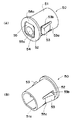
【図6】本発明に係る不正開放防止機構を構成する遮蔽キャップの斜視図である。
【図7】上記遮蔽キャップの平面図である。
【図8】上記遮蔽キャップの断面図である。
【図9】上記サブ基板アセンブリの不正開放防止機構を、遮蔽キャップが取りつけられた状態および取りつけられる前の状態について示す正面図である。
【図10】上記サブ基板アセンブリにおける不正開放防止機構を構成する部分を遮蔽キャップが取りつけられた状態で示す断面図である。
【図11】上記遮蔽キャップの蓋部を破壊して押し下げた状態を示す平面図および断面図である。
【図12】遮蔽キャップの異なる例を示す斜視図である。
【符号の説明】
1 本体ケース
2 カバー
3 表示窓
4 スタートレバー
5 停止ボタン
6 メダル投入口
7 メダル払出口
8 受け皿
11 上部スピーカ
12a 左表示基板
12b 中央表示基板
13 回転始動センサ
14 停止ボタン基板
15 遊技メダルセレクター
16 遊技メダル返却通路
17 下部スピーカ
20 サブ基板アセンブリ
21 サブ基板ケース
22 フランジ部
23 基板取付部
23a ネジ挿入孔
25 ネジボス
25a ネジ孔
27 サブ基板ベース
27a ベース側嵌合リブ
28 係止アーム
29 開口
30 サブ基板カバー
30a カバー側嵌合リブ
31 結合ネジ挿入孔
31a 挿入孔ボス
32 入口側挿入孔
32a 位置決め面
32b 嵌合開口
33 奥側挿入孔
34 ネジ挿入貫通孔
35 座ぐり部
35a 座ぐり面
37 係止突起
38 凹部
39 ヒンジアーム
40 サブ制御基板
41 基板貫通孔
42 ROM
45 結合ネジ
46 ネジ部
47 ネジヘッド
47a 十字溝
50,150 遮蔽キャップ
51,151 円筒部
51a 位置決め面
52,152 フランジ部
53,153 係合突起
53a 根元部
54 矩形開口
55 蓋部
55a 凹部
56a 薄肉連結部
56b 連結部
155 薄肉部
SM スロットマシン
H ヒンジ部
DR ドライバー[0001]
BACKGROUND OF THE INVENTION
The present invention relates to a board case for accommodating a control board or the like for controlling the operation of a gaming machine in a gaming machine such as a pachinko machine or a slot machine, and more specifically, the board case in a state in which the board is contained cannot be illegally opened. The present invention relates to a mechanism for preventing unauthorized opening of a substrate case to prevent illegal acts against the above.
[0002]
[Prior art]
In gaming machines such as pachinko machines and slot machines, a control board for controlling the operation of the gaming machine is provided. For example, in a pachinko gaming machine, a game board and a back mechanism board are installed in a storage frame on the back side of the front frame that is assembled to the outer frame so as to be openable and closable, and a control board is attached to the back mechanism board. Similarly, in the slot machine, a control board is attached to the back surface of the opening / closing cover. These control boards control the operation of pachinko machines or slot machines, such as prize ball or medal payout control, opening / closing control of electric accessories, reel rotation control, symbol combination occurrence probability control, etc. A ROM in which control software is recorded is mounted and serves as a central control device that controls the operation of the gaming machine. For this reason, the control board is housed in the board case so that it is not subject to unauthorized modification such as replacement with a counterfeit ROM, and this board case is illegally opened (or illegally left with traces when the case is opened). (Modification) Preventive measures are provided.
[0003]
Examples of such unauthorized opening prevention means include means for fastening a plurality of cleavable screw fastening pairs with special screws. This is a board case composed of a case main body member and a case lid member that can be freely opened and closed on the case main body member, and a screw threaded portion corresponding to each side edge of the case main body member and the case lid member, and A plurality of screw fastening pairs consisting of screw penetration parts are formed, and of these, at least one screw threaded part and screw penetration part can be operated only in the tightening direction. The engagement portion is formed only in the direction, and the engagement portion in the loosening direction is removed in a spiral shape, and is tightened with a screw (hereinafter referred to as “one-way screw” in this specification). In this configuration, a severable cutting part is formed between the case lid member and the screw penetration part.
[0004]
In the above unauthorized opening prevention means, when the administrator opens the board case for maintenance inspection of the control board, the cutting part of the fastening pair fastened with the one-way screw is cut with a tool such as a nipper, and the screw penetration part Is disconnected from the case lid member to release the connection between the case lid member and the case main body member and open the case lid member. In this way, the case lid member is opened and maintenance inspection is performed, but after the maintenance inspection is completed, the other fastening pair that has not yet been fastened is fastened using a one-way screw and the case lid member is attached to the case body member・ Close. In addition, a board management sticker that displays the board management number and the opening history is affixed to the board case, and the administrator who opened the label manages the opening date and the name of the person who opened it on this board management sticker. It has become.
[0005]
[Problems to be solved by the invention]
According to the unauthorized opening prevention means as described above, the one-way screw generally cannot be rotated in the loosening direction, and it is necessary to cut the cutting part when opening the board case. The trace remains clear and it appears impossible to open it illegally. However, even with such unauthorized modification prevention means, it has been pointed out that clever unauthorized modification acts that circumvent this are sporadically discovered, and it is still difficult to achieve perfection with such means alone. ing.
[0006]
For example, an unauthorized person removes a one-way screw using special means without damaging it, and re-fastens the one-way screw removed after unauthorized modification to its original position, making it difficult to detect fraud at first glance. Examples of such remodeling have been discovered, and such cases have gradually spread. This is a serious problem that impairs the essential function of the board case to prevent unauthorized modification, and an early improvement has been desired.
[0007]
In addition, in the configuration in which the case is opened by cutting the fastening pair cutting portion at each maintenance inspection as described above, the number of maintenance inspections corresponding to the number of fastening pairs is possible, and the maintenance is performed more than that. There is a problem that it is difficult to deal with inspections, such as the need to replace the entire case.
[0008]
The present invention has been made in view of the above problems, and the case for maintenance inspections and the like can be opened any number of times. It is an object of the present invention to provide an unauthorized opening prevention mechanism configured to effectively prevent unauthorized opening, and to provide a gaming machine board case that can be used for fair games.
[0009]
[Means for Solving the Problems]
To achieve the above object, the present invention includes a case main body member attached to a gaming machine and a case lid member attached to the case main body member, and the case interior formed by attaching the case lid member to the case main body member In the case where the control board is accommodated in the case, the unauthorized opening prevention mechanism has the case body member and the case with the case lid member attached to the case body member.lidCoupling for joining parts togetherscrewWhen,Recessed into a cylindrical shape from the outer surface of the case lid memberFormed on the case lid member, combined to join the case lid member to the case bodyscrewAnd a shielding member that covers the insertion hole and is attached to the case lid member. AndThe insertion hole is located at the inlet portion, and the insertion side insertion hole to which the shielding member is mounted. In the state where the case lid member is attached to the case main body member, a screw hole to be screwed with the coupling screw is formed in a portion facing the screw penetration insertion hole in the case main body member,Connected to insertion holescrewInsertScrew the screw part into the screw hole through the screw insertion hole.JoinscrewAfter connecting the case lid member to the case body by theEntrance sideConnect to the insertion hole and joinscrewIn which the shielding member isEntrance sideOnce it is installed in the insertion holeFrom the outsideCan be removed from the case lidHowever, it is configured to be removable from the inner surface side of the case lid member. Further, the shielding member has a breakable portion that can be broken at a portion that covers the insertion hole and covers the insertion hole when the shielding member is attached to the case lid member. Can perform unlink operation byIt is configured as follows.
[0010]
In addition, thisIn the unauthorized opening prevention mechanism of the substrate case, the shielding member includes a cylindrical portion having an outer diameter that is fitted and inserted into the inlet side insertion hole, and a flange portion that protrudes in an outer peripheral direction on one end side of the cylindrical portion, An engagement protrusion provided on the outer peripheral surface of the cylindrical portion so as to be elastically deformable on the inner diameter side, and the engagement protrusion is inserted when the cylindrical portion is fitted and inserted into the inlet-side insertion hole. When the flange portion is inserted to a position close to the inlet end portion of the inlet-side insertion hole when elastically deformed to the inner diameter side and enters the inlet-side insertion hole, the inner peripheral surface of the inlet-side insertion hole The engagement projection is configured to enter and be locked into an engagement opening formed to expand to the outer diameter side, and the engagement opening is formed through the inner surface side of the case lid member. And the engagement member from the inner surface side of the case lid member through the engagement opening. Push the projections on the inner diameter side to release the engagement between the engaging opening, the shielding member can be detached from the inlet side insertion holeIt is.
In addition,A counterbore portion having a recessed shape capable of accommodating the flange portion is provided at an inlet end portion of the inlet side insertion hole, and the flange portion is inserted when the cylindrical portion is fitted and inserted into the inlet side insertion hole. Is preferably located so as to enter the counterbore.
Further, the breaking portion is located in a lid opening formed in a portion that covers the insertion hole when the shielding member covers the insertion hole and is attached to the case lid member, and has a thin connection on one side. The cover is connected to a portion covering the insertion hole via a portion, and has a lid portion connected to the portion covering the insertion hole via a breaking connection portion on the other side, and the breaking connection portion is cut and broken. Then, the lid portion is pushed into the inlet side insertion hole with the thin-walled connecting portion as a center, and a tool for releasing the coupling screw is inserted into the inlet side insertion hole through the lid opening. In addition, it is preferable that the coupling release operation by the coupling screw can be performed.
In this case, a concave portion is provided on the upper surface of the lid portion to serve as a positioning guide for pressing the tip of the tool to push the lid portion into the insertion-side insertion hole to cut and break the fracture connecting portion. Is preferred.
[0011]
According to the unauthorized opening prevention mechanism configured as described above, first, the case lid member is attached to the case body member in which the control board is disposed, and the coupling member (for example, the coupling screw) is inserted into the insertion hole. The coupling member is coupled from the outside through the hole (for example, the tip of the screwdriver is inserted into the insertion hole and the fastening screw is screw-coupled), and the case lid member is coupled to the case body member by this coupling member. Later, a shielding member is attached to the insertion hole. As a result, since the insertion hole is blocked by the shielding member, the operation of releasing the coupling member from the insertion hole cannot be performed (for example, the tip of the driver cannot be inserted into the insertion hole). The lid member cannot be opened or removed from the case body member.
[0012]
Here, since the shielding member is configured so that it cannot be removed from the case lid member once it is attached to the insertion hole, the unauthorized opening of the case lid member can be reliably prevented. For example, if the shielding member is destroyed, it cannot be removed. However, when the shielding member is destroyed in this way, it can be easily detected, so that illegal acts can be effectively suppressed. Similarly, it is configured so that the coupling member cannot be released from the outside through the insertion hole unless at least a part of the shielding member is destroyed. In other words, if the shielding member is partially destroyed, Although it is configured so that the coupling member can be uncoupled from the outside, if the case lid member is opened by illegally uncoupling the coupling means by breaking a part of the shielding member, the destruction Since traces remain and fraudulent activity can be easily found from the traces, fraudulent activity can be effectively suppressed.
[0013]
However, in the unauthorized opening prevention mechanism of the present invention, the insertion hole is opened to the outside by destroying a part of the shielding member, the coupling member is released from the outside through the insertion hole, and the case lid member is Maintenance or inspection of the control board or the like disposed inside after being opened or removed is made possible. For this reason, as described above, it is preferable that the shielding member is provided with a breaking portion so that the breaking portion can be broken and the coupling member can be uncoupled from the outside via the insertion hole. When the maintenance inspection is completed in this way, for example, after removing the shielding member from the inside of the case lid member, the case lid member is attached to the case body member, the coupling member is inserted into the insertion hole, and the insertion hole is inserted. A coupling member is coupled from the outside, the case lid member is coupled to the case body member by the coupling member, and then a new shielding member is attached to the insertion hole. By exchanging the shielding member in this way, maintenance and inspection work can be performed any number of times.
[0014]
DETAILED DESCRIPTION OF THE INVENTION
A preferred embodiment of the present invention will be described below with reference to the drawings, taking as an example the case where a substrate case is applied to a slot machine.
[0015]
A typical example of the slot machine is shown in FIG. 2, and this slot machine SM has a substantially rectangular parallelepiped shape composed of a main body case 1 whose front surface is open and a
[0016]
The unauthorized opening prevention mechanism according to the present invention is applied to the
[0017]
The
[0018]
The
[0019]
A locking
[0020]
In this way, the
[0021]
The
[0022]
Further, when the
[0023]
The
[0024]
In the state of being coupled by the
[0025]
As shown in FIG. 6, the shielding
[0026]
Further, as shown in FIGS. 7 and 8, a rectangular plate-
[0027]
The shielding
[0028]
As a result, the shielding
[0029]
As shown in FIGS. 4 and 5, a
[0030]
Next, a description will be given of the case where the maintenance inspection of the
[0031]
After the
[0032]
If the connecting
[0033]
The
[0034]
A different example of the shielding cap is shown in FIG. The shielding
[0035]
Similarly to the above-described
[0036]
Once this
[0037]
In the above description, the sub-board assembly attached to the back surface of the slot machine cover has been described as an example. However, the unauthorized opening prevention mechanism of the present invention is not limited to this. For example, a similar configuration can be applied to a substrate case (so-called a case having a main control substrate) provided in another part of the slot machine (inside the main body case or the like), and a substrate disposed inside the pachinko machine. It can also be applied to cases. Furthermore, in the above example, the unauthorized opening prevention mechanism according to the present invention may be used for the
[0038]
【The invention's effect】
As described above, according to the present invention, the case lid member is attached to the case body member in which the control board is disposed, the coupling member is inserted into the insertion hole, and the coupling member is coupled from the outside through the insertion hole. If the case lid member is coupled to the case body member by this coupling member, and then the shielding member is attached to the insertion hole, the operation of releasing the coupling member from the insertion hole cannot be performed. It cannot be opened or removed from the case body member. Here, since the shielding member is configured so that it cannot be removed from the case lid member once it is attached to the insertion hole, the unauthorized opening of the case lid member can be reliably prevented. In addition, when the case lid member is illegally opened by destroying the shielding member, or when the coupling member is released from the outside by destroying the lid portion of the shielding member, the destruction trace remains. Therefore, fraudulent acts can be easily found from these traces, and fraudulent acts can be prevented in advance and effectively.
[0039]
In the present invention, the insertion hole is opened to the outside by destroying a part of the shielding member (for example, the lid portion), and the coupling member is released from the outside through the insertion hole to open the case lid member. Alternatively, it is possible to perform maintenance and inspection of the control board or the like that is removed and disposed inside. When the maintenance inspection is completed, for example, after removing the shielding member from the inside of the case lid member, the case lid member is attached to the case body member, the coupling member is inserted into the insertion hole, and the coupling member is externally inserted through the insertion hole. The case lid member is joined to the case main body member by this joining member, and then a new shielding member can be attached to the insertion hole. By exchanging the shielding member in this way, maintenance and inspection work can be performed any number of times.
[Brief description of the drawings]
FIG. 1 is a cross-sectional view showing a portion of a sub-board assembly that constitutes an unauthorized opening prevention mechanism according to the present invention before a shielding cap is attached.
FIG. 2 is an external perspective view of a slot machine to which an unauthorized opening prevention mechanism according to the present invention is applied.
FIG. 3 is a front view showing the back surface of the cover in a state where the cover constituting the slot machine is opened.
FIG. 4 is a front view showing a sub-board assembly attached to the back surface of the cover.
FIG. 5 is a perspective view of the sub-board assembly.
FIG. 6 is a perspective view of a shielding cap constituting the unauthorized opening prevention mechanism according to the present invention.
FIG. 7 is a plan view of the shielding cap.
FIG. 8 is a cross-sectional view of the shielding cap.
FIG. 9 is a front view showing the unauthorized opening prevention mechanism of the sub-board assembly in a state where a shielding cap is attached and a state before being attached.
FIG. 10 is a cross-sectional view showing a portion constituting the unauthorized opening prevention mechanism in the sub-board assembly in a state where a shielding cap is attached.
FIGS. 11A and 11B are a plan view and a cross-sectional view showing a state in which the lid portion of the shielding cap is broken and pushed down.
FIG. 12 is a perspective view showing a different example of the shielding cap.
[Explanation of symbols]
1 Body case
2 Cover
3 Display window
4 Start lever
5 Stop button
6 medal slot
7 Medal payment exit
8 saucer
11 Upper speaker
12a Left display board
12b Central display board
13 Rotation start sensor
14 Stop button board
15 game medal selector
16 Game medal return passage
17 Lower speaker
20 Sub-board assembly
21 Sub-board case
22 Flange
23 Board mounting part
23a Screw insertion hole
25 Screw boss
25a Screw hole
27 Sub-board base
27a Base side mating rib
28 Locking arm
29 opening
30 Sub-board cover
30a Cover side fitting rib
31 Connecting screw insertion hole
31a Insertion hole boss
32 Entrance side insertion hole
32a Positioning surface
32b Mating opening
33 Back insertion hole
34 Screw insertion through hole
35 Counterbore
35a Counterbore surface
37 Locking protrusion
38 recess
39 Hinge arm
40 Sub-control board
41 Substrate through hole
42 ROM
45 coupling screw
46 Screw part
47 Screw head
47a Cross groove
50,150 shielding cap
51,151 cylindrical part
51a Positioning surface
52,152 Flange
53,153 Engagement protrusion
53a Root
54 Rectangular opening
55 Lid
55a recess
56a Thin connector
56b connecting part
155 Thin part
SM slot machine
H Hinge part
DR driver
Claims (4)
前記ケース本体部材に前記ケース蓋部材を取り付けた状態で前記ケース本体部材と前記ケース蓋部材を一体結合するための結合ネジと、
前記ケース蓋部材の外面から円筒状に窪んで前記ケース蓋部材に形成され、前記ケース蓋部材を前記ケース本体に結合させるために前記結合ネジを挿入する挿入孔と、
前記挿入孔を覆って前記ケース蓋部材に取り付けられる遮蔽部材とを備えて構成され、
前記挿入孔が、入口部に位置して前記遮蔽部材が装着される入口側挿入孔と、前記入口側挿入孔より小径で孔底面から前記ケース蓋部材の内側に貫通して形成されたネジ挿入貫通孔とから形成され、前記ケース本体部材に前記ケース蓋部材を取り付けた状態で、前記ケース本体部材における前記ネジ貫通挿入孔と対向する部分に、前記結合ネジと螺合するネジ孔が形成されており、
前記挿入孔に前記結合ネジを挿入し、そのネジ部を前記ネジ貫通挿入孔を通して前記ネジ孔に螺合させて前記結合ネジにより前記ケース蓋部材を前記ケース本体に結合させた後、前記遮蔽部材を前記入口側挿入孔に取り付けて前記結合ネジの結合解除操作を阻止するように構成されており、
前記遮蔽部材は前記入口側挿入孔に一旦取り付けた後においては外部からは前記ケース蓋部材から取り外すことができないが、前記ケース蓋部材の内面側からは取り外すことが可能に構成されており、
前記遮蔽部材は、前記挿入孔を覆って前記ケース蓋部材に取り付けられたときに前記挿入孔を覆う部分に破壊可能な破壊部を有し、前記破壊部を破壊して前記挿入孔を介して外部から前記結合ネジによる結合解除操作を行うことができるように構成されており、
前記遮蔽部材は、前記入口側挿入孔に嵌合挿入される外径を有した円筒部と、前記円筒部の一端側に外周方向に突出したフランジ部と、前記円筒部の外周面に内径側に弾性変形可能に設けられた係合突起とを有して構成され、
前記円筒部が前記入口側挿入孔に嵌合挿入されたときに前記係合突起が内径側に弾性変形して前記入口側挿入孔内に入り込み、前記フランジ部が前記入口側挿入孔の入口端部に近接する位置まで挿入されたときに、前記入口側挿入孔の内周面に外径側に広がって形成された係合開口内に前記係合突起が入り込んで係止されるように構成されており、
前記係合開口は、前記ケース蓋部材の内面側に貫通開口しており、前記ケース蓋部材の内面側から前記係合開口を介して前記係合突起を内径側に押し込んで前記係合開口との係止を解除し、前記遮蔽部材を前記入口側挿入孔から取り外すことが可能であることを特徴とする基板ケースの不正防止機構。A board that includes a case main body member attached to a gaming machine and a case lid member attached to the case main body member, and accommodates a control board inside the case formed by attaching the case lid member to the case main body member In case
A coupling screw for integrally coupling the case body member and the case lid member in a state where the case lid member is attached to the case body member;
An insertion hole into which the coupling screw is inserted in order to couple the case lid member to the case body, and is formed in the case lid member in a cylindrical shape from the outer surface of the case lid member;
A shielding member that covers the insertion hole and is attached to the case lid member;
The insertion hole is located at the inlet portion and the insertion side insertion hole on which the shielding member is mounted, and the screw insertion that is smaller in diameter than the inlet side insertion hole and penetrates from the bottom surface to the inside of the case lid member. A screw hole that is screwed with the coupling screw is formed in a portion of the case body member that faces the screw penetration insertion hole in a state where the case lid member is attached to the case body member. And
The coupling screw is inserted into the insertion hole, the screw portion is screwed into the screw hole through the screw penetration insertion hole, and the case lid member is coupled to the case body by the coupling screw, and then the shielding member Is configured to prevent the coupling screw from being uncoupled by attaching to the inlet-side insertion hole,
The shielding member is configured to be removable from the outside of the case lid member from the outside after being temporarily attached to the inlet side insertion hole, but is removable from the inner surface side of the case lid member,
The shielding member has a breakable portion that can be broken at a portion that covers the insertion hole and covers the insertion hole when attached to the case lid member, and breaks the broken portion through the insertion hole. It is configured to be able to perform a coupling release operation with the coupling screw from the outside ,
The shielding member includes a cylindrical portion having an outer diameter that is fitted and inserted into the inlet-side insertion hole, a flange portion that protrudes in an outer peripheral direction on one end side of the cylindrical portion, and an inner diameter side on an outer peripheral surface of the cylindrical portion. And an engaging protrusion provided in an elastically deformable manner,
When the cylindrical portion is fitted and inserted into the inlet side insertion hole, the engagement protrusion is elastically deformed into the inner diameter side and enters the inlet side insertion hole, and the flange portion is the inlet end of the inlet side insertion hole. The engagement protrusion is inserted into the engagement opening formed on the inner peripheral surface of the inlet-side insertion hole so as to expand to the outer diameter side and locked when inserted to a position close to the portion. Has been
The engagement opening is opened through to the inner surface side of the case lid member, and the engagement protrusion is pushed into the inner diameter side through the engagement opening from the inner surface side of the case lid member. The board case fraud prevention mechanism is characterized in that it can be unlocked and the shielding member can be removed from the inlet side insertion hole .
前記破壊連結部を切断破壊して前記蓋部を前記薄肉連結部を中心として前記入口側挿入孔内に揺動させながら押し込み、前記蓋開口を通って前記入口側挿入孔内に前記結合ネジを解除するための工具を挿入し、前記結合ネジによる結合解除操作を行うことができるように構成されていることを特徴とする請求項1もしくは2に記載の基板ケースの不正開放防止機構。The breaking portion is located in a lid opening formed in a portion that covers the insertion hole when the shielding member covers the insertion hole and is attached to the case lid member, and a thin coupling portion is provided on one side. Connected to the portion covering the insertion hole via, and having a lid portion provided on the other side connected to the portion covering the insertion hole via the fracture connecting portion,
The breaking connection portion is cut and broken, and the lid portion is pushed while swinging into the inlet side insertion hole around the thin-walled coupling portion, and the coupling screw is inserted into the inlet side insertion hole through the lid opening. 3. The unauthorized opening prevention mechanism for a substrate case according to claim 1 or 2 , wherein a tool for releasing is inserted and a connection releasing operation by the connecting screw can be performed.
Priority Applications (1)
| Application Number | Priority Date | Filing Date | Title |
|---|---|---|---|
| JP2002152997A JP4125546B2 (en) | 2002-05-27 | 2002-05-27 | Mechanism for preventing unauthorized opening of circuit board case |
Applications Claiming Priority (1)
| Application Number | Priority Date | Filing Date | Title |
|---|---|---|---|
| JP2002152997A JP4125546B2 (en) | 2002-05-27 | 2002-05-27 | Mechanism for preventing unauthorized opening of circuit board case |
Publications (3)
| Publication Number | Publication Date |
|---|---|
| JP2003340092A JP2003340092A (en) | 2003-12-02 |
| JP2003340092A5 JP2003340092A5 (en) | 2005-10-13 |
| JP4125546B2 true JP4125546B2 (en) | 2008-07-30 |
Family
ID=29770185
Family Applications (1)
| Application Number | Title | Priority Date | Filing Date |
|---|---|---|---|
| JP2002152997A Expired - Fee Related JP4125546B2 (en) | 2002-05-27 | 2002-05-27 | Mechanism for preventing unauthorized opening of circuit board case |
Country Status (1)
| Country | Link |
|---|---|
| JP (1) | JP4125546B2 (en) |
Families Citing this family (17)
| Publication number | Priority date | Publication date | Assignee | Title |
|---|---|---|---|---|
| JP4895252B2 (en) * | 2005-09-15 | 2012-03-14 | サミー株式会社 | Board unit for gaming machines |
| JP2007267884A (en) * | 2006-03-30 | 2007-10-18 | Samii Kk | Board case of game machine |
| JP5116132B2 (en) * | 2006-03-30 | 2013-01-09 | サミー株式会社 | Board case unit for gaming machines |
| JP4986015B2 (en) * | 2006-05-24 | 2012-07-25 | サミー株式会社 | Game control board assembly sealing structure and gaming machine |
| JP2008012351A (en) * | 2007-10-01 | 2008-01-24 | Samii Kk | Board casing for game machine |
| JP4878349B2 (en) * | 2008-02-01 | 2012-02-15 | マルホン工業株式会社 | Control board storage case for gaming machine |
| JP4736062B2 (en) * | 2008-02-25 | 2011-07-27 | タイヨーエレック株式会社 | Unit for storing control board for gaming machine and gaming machine |
| JP5499439B2 (en) * | 2008-03-05 | 2014-05-21 | 株式会社三洋物産 | Game machine |
| JP5838459B2 (en) * | 2010-10-19 | 2016-01-06 | 株式会社北電子 | Game machine |
| JP5830745B2 (en) * | 2011-03-02 | 2015-12-09 | 株式会社北電子 | Game machine |
| JP5728691B2 (en) * | 2011-03-22 | 2015-06-03 | 株式会社北電子 | Seal structure |
| JP5823575B1 (en) * | 2014-06-26 | 2015-11-25 | 山佐株式会社 | SEALING MEMBER, SEALING STRUCTURE AND GAME MACHINE |
| JP5823640B1 (en) * | 2015-02-02 | 2015-11-25 | 山佐株式会社 | Gaming machine sealing structure and gaming machine |
| JP5895081B1 (en) * | 2015-04-13 | 2016-03-30 | 山佐株式会社 | Protective cover for gaming machine and gaming machine |
| JP5895082B1 (en) * | 2015-04-13 | 2016-03-30 | 山佐株式会社 | Protective cover for gaming machine and gaming machine |
| JP6015840B2 (en) * | 2015-11-05 | 2016-10-26 | 株式会社三洋物産 | Game machine |
| WO2020179851A1 (en) * | 2019-03-05 | 2020-09-10 | パナソニックIpマネジメント株式会社 | Recording control system, control device, recording control method, and recording medium |
-
2002
- 2002-05-27 JP JP2002152997A patent/JP4125546B2/en not_active Expired - Fee Related
Also Published As
| Publication number | Publication date |
|---|---|
| JP2003340092A (en) | 2003-12-02 |
Similar Documents
| Publication | Publication Date | Title |
|---|---|---|
| JP4125546B2 (en) | Mechanism for preventing unauthorized opening of circuit board case | |
| JP5001607B2 (en) | Board case for gaming machine and gaming machine | |
| JP2003340125A (en) | Illicit opening preventive mechanism of base board case | |
| JP2010201107A (en) | Game machine | |
| JP2004073512A (en) | Sealing structure | |
| JP4087153B2 (en) | Mechanism for preventing unauthorized opening of circuit board case | |
| JP2004065791A (en) | Circuit board case | |
| JP3957787B2 (en) | Board storage box for gaming machines | |
| JP4057624B2 (en) | Board storage box for gaming machines | |
| JP2012005682A (en) | Board storage case for game machine and game machine provided therewith | |
| JP4453133B2 (en) | Game machine | |
| JP4662506B2 (en) | Board storage box for gaming machines | |
| JP3998698B2 (en) | Board storage box for gaming machines | |
| JP4057619B2 (en) | Board storage box for gaming machines | |
| JP4057622B2 (en) | Board storage box for gaming machines | |
| JP4057621B2 (en) | Board storage box for gaming machines | |
| JP4003640B2 (en) | Game machine | |
| JP4057602B2 (en) | Board storage box for gaming machines | |
| JPH09239096A (en) | Base board containing box of game machine | |
| JP4057606B2 (en) | Board storage box for gaming machines | |
| JP4087154B2 (en) | Mechanism for preventing unauthorized opening of circuit board case | |
| JP4512797B2 (en) | Revolving machine | |
| JPH09290054A (en) | Substrate housing box for game machine | |
| JP4057620B2 (en) | Board storage box for gaming machines | |
| JP2009285516A5 (en) |
Legal Events
| Date | Code | Title | Description |
|---|---|---|---|
| A621 | Written request for application examination |
Free format text: JAPANESE INTERMEDIATE CODE: A621 Effective date: 20050427 |
|
| A521 | Written amendment |
Free format text: JAPANESE INTERMEDIATE CODE: A523 Effective date: 20050602 |
|
| A131 | Notification of reasons for refusal |
Free format text: JAPANESE INTERMEDIATE CODE: A131 Effective date: 20071116 |
|
| A521 | Written amendment |
Free format text: JAPANESE INTERMEDIATE CODE: A523 Effective date: 20080111 |
|
| A131 | Notification of reasons for refusal |
Free format text: JAPANESE INTERMEDIATE CODE: A131 Effective date: 20080208 |
|
| A521 | Written amendment |
Free format text: JAPANESE INTERMEDIATE CODE: A523 Effective date: 20080401 |
|
| TRDD | Decision of grant or rejection written | ||
| A01 | Written decision to grant a patent or to grant a registration (utility model) |
Free format text: JAPANESE INTERMEDIATE CODE: A01 Effective date: 20080425 |
|
| A01 | Written decision to grant a patent or to grant a registration (utility model) |
Free format text: JAPANESE INTERMEDIATE CODE: A01 |
|
| A61 | First payment of annual fees (during grant procedure) |
Free format text: JAPANESE INTERMEDIATE CODE: A61 Effective date: 20080508 |
|
| R150 | Certificate of patent or registration of utility model |
Free format text: JAPANESE INTERMEDIATE CODE: R150 |
|
| FPAY | Renewal fee payment (event date is renewal date of database) |
Free format text: PAYMENT UNTIL: 20110516 Year of fee payment: 3 |
|
| FPAY | Renewal fee payment (event date is renewal date of database) |
Free format text: PAYMENT UNTIL: 20120516 Year of fee payment: 4 |
|
| FPAY | Renewal fee payment (event date is renewal date of database) |
Free format text: PAYMENT UNTIL: 20130516 Year of fee payment: 5 |
|
| FPAY | Renewal fee payment (event date is renewal date of database) |
Free format text: PAYMENT UNTIL: 20130516 Year of fee payment: 5 |
|
| FPAY | Renewal fee payment (event date is renewal date of database) |
Free format text: PAYMENT UNTIL: 20130516 Year of fee payment: 5 |
|
| FPAY | Renewal fee payment (event date is renewal date of database) |
Free format text: PAYMENT UNTIL: 20130516 Year of fee payment: 5 |
|
| FPAY | Renewal fee payment (event date is renewal date of database) |
Free format text: PAYMENT UNTIL: 20140516 Year of fee payment: 6 |
|
| R250 | Receipt of annual fees |
Free format text: JAPANESE INTERMEDIATE CODE: R250 |
|
| R250 | Receipt of annual fees |
Free format text: JAPANESE INTERMEDIATE CODE: R250 |
|
| LAPS | Cancellation because of no payment of annual fees |