JP4091006B2 - Electroacoustic transducer - Google Patents
Electroacoustic transducer Download PDFInfo
- Publication number
- JP4091006B2 JP4091006B2 JP2004045937A JP2004045937A JP4091006B2 JP 4091006 B2 JP4091006 B2 JP 4091006B2 JP 2004045937 A JP2004045937 A JP 2004045937A JP 2004045937 A JP2004045937 A JP 2004045937A JP 4091006 B2 JP4091006 B2 JP 4091006B2
- Authority
- JP
- Japan
- Prior art keywords
- frame
- electroacoustic transducer
- armature
- magnets
- housing
- Prior art date
- Legal status (The legal status is an assumption and is not a legal conclusion. Google has not performed a legal analysis and makes no representation as to the accuracy of the status listed.)
- Expired - Lifetime
Links
- 229920006332 epoxy adhesive Polymers 0.000 claims description 29
- 239000000853 adhesive Substances 0.000 claims description 26
- 230000001070 adhesive effect Effects 0.000 claims description 26
- 230000005284 excitation Effects 0.000 claims description 18
- 239000002184 metal Substances 0.000 claims description 17
- 230000002093 peripheral effect Effects 0.000 claims description 13
- 238000003466 welding Methods 0.000 description 7
- 238000004804 winding Methods 0.000 description 6
- 229920005989 resin Polymers 0.000 description 5
- 239000011347 resin Substances 0.000 description 5
- 238000005452 bending Methods 0.000 description 3
- 238000001746 injection moulding Methods 0.000 description 3
- 229910000679 solder Inorganic materials 0.000 description 2
- 239000003522 acrylic cement Substances 0.000 description 1
- 238000006243 chemical reaction Methods 0.000 description 1
- 230000007423 decrease Effects 0.000 description 1
- 238000006073 displacement reaction Methods 0.000 description 1
- 230000004907 flux Effects 0.000 description 1
- 238000009413 insulation Methods 0.000 description 1
- 239000000696 magnetic material Substances 0.000 description 1
- 239000000463 material Substances 0.000 description 1
- 230000000149 penetrating effect Effects 0.000 description 1
- 230000000630 rising effect Effects 0.000 description 1
- 239000013464 silicone adhesive Substances 0.000 description 1
Images


Description
本願発明は、いわゆるバランスドアーマチャ型の電気音響変換器に関するものである。 The present invention relates to a so-called balanced armature type electroacoustic transducer.
バランスドアーマチャ型の電気音響変換器は、低消費電力でかつ電気音響変換効率が高く、小型であっても所要の出力を得ることができるので、補聴器用のレシーバ等として多く用いられている。 Balanced armature electroacoustic transducers are often used as receivers for hearing aids because they have low power consumption, high electroacoustic conversion efficiency, and can obtain a required output even when they are small.
このバランスドアーマチャ型の電気音響変換器は、例えば「特許文献1」に記載されているように、ハウジング内に、ダイヤフラムとこれを振動させる駆動ユニットとが収容された構成となっている。 This balanced armature type electroacoustic transducer has a configuration in which a diaphragm and a drive unit that vibrates the diaphragm are accommodated in a housing, as described in, for example, “Patent Document 1”.
そして、この電気音響変換器の駆動ユニットは、所定間隙をおいて対向配置された1対のマグネットと、中心軸が両マグネット間を通るように配置された励磁コイルと、両マグネット間および励磁コイル内を貫通するように配置された金属製のアーマチャとを備えてなり、励磁コイルに信号電流を印加してアーマチャを撓み変形させることによりダイヤフラムを振動させるようになっている。 The drive unit of the electroacoustic transducer includes a pair of magnets arranged to face each other with a predetermined gap, an excitation coil arranged so that a central axis passes between both magnets, and between the magnets and the excitation coil. And a metal armature disposed so as to penetrate through the diaphragm, and the diaphragm is vibrated by applying a signal current to the exciting coil to bend and deform the armature.
その際、上記アーマチャは、その一端部において、励磁コイルを磁性ホルダとは反対側から略コ字状に囲むように配置された金属製のフレームの中間部に固定されるとともに、その所定部位において、連結片を介してダイヤフラムに連結されている。 At that time, the armature is fixed at one end of the armature to an intermediate portion of a metal frame disposed so as to surround the exciting coil in a substantially U shape from the side opposite to the magnetic holder, and at the predetermined portion. And connected to the diaphragm via a connecting piece.
しかしながら、このようなバランスドアーマチャ型の電気音響変換器においては、上記「特許文献1」にも記載されているように、フレームの両端部が、両マグネットを保持する磁性ホルダに固定されているので、フレームの中間部に、アーマチャを片持ち支持するのに十分な剛性を確保することが困難となり、このため電気音響変換器の最低共振周波数をあまり高めることができない、という問題がある。 However, in such a balanced armature type electroacoustic transducer, both ends of the frame are fixed to a magnetic holder that holds both magnets, as described in "Patent Document 1". Therefore, it is difficult to secure sufficient rigidity to support the armature in a cantilevered manner in the middle portion of the frame, and therefore there is a problem that the minimum resonance frequency of the electroacoustic transducer cannot be increased so much.
特に、上記「特許文献1」に記載された電気音響変換器のように、フレームとアーマチャとが一体で構成されている場合には、フレームの中間部の剛性を確保することが一層困難なものとなる。 In particular, as in the electroacoustic transducer described in “Patent Document 1”, when the frame and the armature are integrally configured, it is more difficult to ensure the rigidity of the intermediate portion of the frame. It becomes.
これに対し、フレームの板厚を厚くすれば、その中間部の剛性を高めることが可能となるが、このようにした場合には、板厚を厚くした分だけ電気音響変換器が大型化してしまう、という問題がある。しかも、フレームとアーマチャとが一体で構成されている場合には、アーマチャの板厚も厚くなるので、駆動ユニットの他の構成要素とのクリアランスを確保する必要上、電気音響変換器がさらに大型化してしまう、という問題がある。 In contrast, if the thickness of the frame is increased, the rigidity of the intermediate portion can be increased. However, in this case, the electroacoustic transducer becomes larger by the increased thickness. There is a problem that. In addition, when the frame and armature are configured integrally, the armature plate also becomes thicker, so the electroacoustic transducer is further increased in size to ensure clearance from other components of the drive unit. There is a problem that.
本願発明は、このような事情に鑑みてなされたものであって、バランスドアーマチャ型の電気音響変換器において、これをコンパクトな構成に維持した上で、そのアーマチャを片持ち支持するフレームの中間部の剛性を高めることができる電気音響変換器を提供することを目的とするものである。 The present invention has been made in view of such circumstances, and in a balanced armature type electroacoustic transducer, while maintaining this in a compact configuration, the middle of the frame that supports the armature in a cantilevered manner. An object of the present invention is to provide an electroacoustic transducer capable of increasing the rigidity of a part.
本願発明は、フレームの中間部とこれに近接する他の所定部材との間に接着剤が充填された構成とすることにより、上記目的達成を図るようにしたものである。 In the present invention, the above object is achieved by adopting a configuration in which an adhesive is filled between the intermediate portion of the frame and another predetermined member adjacent to the intermediate portion.
すなわち、本願第1発明に係る電気音響変換器は、
ハウジング内に、ダイヤフラムとこのダイヤフラムを振動させる駆動ユニットとが収容されてなる電気音響変換器において、
上記駆動ユニットが、所定間隙をおいて対向配置された1対のマグネットと、これらマグネットを保持する磁性ホルダと、この磁性ホルダと隣接する位置に、中心軸が上記両マグネット間を通るように配置された励磁コイルと、この励磁コイルを上記磁性ホルダとは反対側から略コ字状に囲むように配置されるとともに両端部が上記磁性ホルダに固定された金属製のフレームと、上記両マグネット間および上記励磁コイル内を貫通するように配置され、一端部において上記フレームの中間部に固定されるとともに所定部位において連結片を介して上記ダイヤフラムに連結された金属製のアーマチャとを備えてなり、
上記フレームの中間部が、上記ハウジングの周面壁と所定間隔をおいて配置されており、このフレームの中間部と上記ハウジングの周面壁との間の隙間に接着剤が充填されることにより、このフレームの中間部が上記ハウジングの周面壁に固定されている、ことを特徴とするものである。
That is, the electroacoustic transducer according to the first invention of this application is
In an electroacoustic transducer in which a diaphragm and a drive unit that vibrates the diaphragm are housed in a housing.
The drive unit is arranged with a pair of magnets facing each other with a predetermined gap, a magnetic holder for holding the magnets, and a central axis passing between the magnets at a position adjacent to the magnetic holder. An excitation coil, a metal frame that is disposed so as to surround the excitation coil in a substantially U shape from the opposite side of the magnetic holder, and both ends are fixed to the magnetic holder, and between the two magnets And a metal armature that is disposed so as to penetrate the inside of the exciting coil, is fixed to an intermediate portion of the frame at one end, and is connected to the diaphragm via a connecting piece at a predetermined portion,
Middle portion of the frame, are arranged at a peripheral wall with a predetermined distance of the housing, the gap adhesive is filled in Rukoto between peripheral wall of the intermediate portion and the housing of the frame, the The middle part of the frame is fixed to the peripheral wall of the housing .
また、本願第2発明に係る電気音響変換器は、
ハウジング内に、ダイヤフラムとこのダイヤフラムを振動させる駆動ユニットとが収容されてなる電気音響変換器において、
上記駆動ユニットが、所定間隙をおいて対向配置された1対のマグネットと、これらマグネットを保持する磁性ホルダと、この磁性ホルダと隣接する位置に、中心軸が上記両マグネット間を通るように配置された励磁コイルと、この励磁コイルを上記磁性ホルダとは反対側から略コ字状に囲むように配置されるとともに両端部が上記磁性ホルダに固定された金属製のフレームと、上記両マグネット間および上記励磁コイル内を貫通するように配置され、一端部において上記フレームの中間部に固定されるとともに所定部位において連結片を介して上記ダイヤフラムに連結された金属製のアーマチャとを備えてなり、
上記励磁コイルが、該励磁コイル内を上記アーマチャと略平行に貫通するように配置されたボビンに支持されており、
このボビンの一端部が、上記フレームの中間部と所定間隔をおいて配置されており、このボビンの一端部と上記フレームの中間部との間の隙間に接着剤が充填されることにより、このボビンの一端部に上記フレームの中間部が固定されている、ことを特徴とするものである。
In addition, the electroacoustic transducer according to the second invention of the present application is
In an electroacoustic transducer in which a diaphragm and a drive unit that vibrates the diaphragm are housed in a housing.
The drive unit is arranged with a pair of magnets facing each other with a predetermined gap, a magnetic holder for holding the magnets, and a central axis passing between the magnets at a position adjacent to the magnetic holder. An excitation coil, a metal frame that is disposed so as to surround the excitation coil in a substantially U shape from the opposite side of the magnetic holder, and both ends are fixed to the magnetic holder, and between the two magnets And a metal armature that is disposed so as to penetrate the inside of the exciting coil, is fixed to an intermediate portion of the frame at one end, and is connected to the diaphragm via a connecting piece at a predetermined portion,
The excitation coil is supported by a bobbin disposed so as to penetrate the excitation coil substantially parallel to the armature,
One end of the bobbin, is disposed at an intermediate portion by a predetermined distance of the frame, by Rukoto adhesive gap is filled between the intermediate portion of the one end portion and the frame of the bobbin, this An intermediate portion of the frame is fixed to one end portion of the bobbin .
上記「電気音響変換器」の種類は特に限定されるものではなく、例えば、レシーバ、スピーカ、ブザー等が採用可能である。 The type of the “electroacoustic transducer” is not particularly limited, and for example, a receiver, a speaker, a buzzer, or the like can be employed.
上記「アーマチャ」は、フレームの中間部に固定されているが、その具体的な固定構造は、フレームと別体で構成されたアーマチャが溶接等の固定手段によってフレームに固定された構造であってもよいし、アーマチャがフレームと一体で構成された構造であってもよい。 The above-mentioned “armature” is fixed to the middle part of the frame. The specific fixing structure is a structure in which an armature formed separately from the frame is fixed to the frame by fixing means such as welding. Alternatively, a structure in which the armature is integrally formed with the frame may be used.
上記「所定部位」は、アーマチャにおける一端部以外の部位であれば、その具体的な位置は特に限定されるものではなく、アーマチャの他端部であってもよいし、アーマチャ中間部であってもよい。 As long as the “predetermined part” is a part other than one end part of the armature, the specific position is not particularly limited, and may be the other end part of the armature or the middle part of the armature. Also good.
上記「接着剤」は、フレームの中間部とハウジングの周面壁あるいはボビンの一端部とを接着固定し得るものであれば、特定種類の接着剤に限定されるものではなく、例えば、エポキシ系接着剤、アクリル系接着剤、シリコーン系接着剤、ゴム系接着剤等が採用可能である。また、この「接着剤」の充填量や充填範囲についても、特に限定されるものではない。 The “adhesive” is not limited to a specific type of adhesive as long as it can fix and fix the intermediate portion of the frame and the peripheral wall of the housing or one end of the bobbin. An adhesive, an acrylic adhesive, a silicone adhesive, a rubber adhesive, or the like can be used. Further, the filling amount and filling range of the “adhesive” are not particularly limited.
上記構成に示すように、本願発明に係る電気音響変換器は、その駆動ユニットが、所定間隙をおいて対向配置された1対のマグネットと、これらマグネットを保持する磁性ホルダと、この磁性ホルダと隣接する位置に、中心軸が両マグネット間を通るように配置された励磁コイルと、この励磁コイルを磁性ホルダとは反対側から略コ字状に囲むように配置されるとともに両端部が磁性ホルダに固定された金属製のフレームと、両マグネット間および励磁コイル内を貫通するように配置され、一端部においてフレームの中間部に固定されるとともに所定部位において連結片を介してダイヤフラムに連結された金属製のアーマチャとを備えた構成となっているので、励磁コイルに所定の信号電流を印加してアーマチャを撓み変形させることにより、ダイヤフラムを振動させることができる。 As shown in the above configuration, in the electroacoustic transducer according to the present invention, the drive unit includes a pair of magnets arranged to face each other with a predetermined gap, a magnetic holder for holding these magnets, and the magnetic holder An excitation coil arranged so that the central axis passes between both magnets at adjacent positions, and the excitation coil is arranged so as to surround the excitation coil in a substantially U shape from the opposite side of the magnetic holder, and both ends are magnetic holders A metal frame fixed to the magnet and disposed between the magnets and the inside of the exciting coil, fixed to the middle part of the frame at one end, and connected to the diaphragm via a connecting piece at a predetermined portion. Since it has a configuration with a metal armature, by applying a predetermined signal current to the exciting coil and bending the armature, It is possible to vibrate the diaphragm.
その際、本願第1発明に係る電気音響変換器は、そのフレームの中間部がハウジングの周面壁と所定間隔をおいて配置されているが、これらフレームの中間部とハウジングの周面壁との間の隙間には接着剤が充填されているので、この接着剤によってフレームとハウジングとが接着固定されることとなり、これによりフレームの中間部の剛性を高めることができる。 In that case, in the electroacoustic transducer according to the first invention of this application, the intermediate portion of the frame is arranged at a predetermined distance from the peripheral wall of the housing, but between the intermediate portion of the frame and the peripheral wall of the housing. Since the gap is filled with an adhesive, the frame and the housing are bonded and fixed by the adhesive, thereby increasing the rigidity of the intermediate portion of the frame.
また、本願第2発明に係る電気音響変換器は、その励磁コイルが、該励磁コイル内をアーマチャと略平行に貫通するように配置されたボビンに支持されるとともに、このボビンの一端部がフレームの中間部と所定間隔をおいて配置されているが、これらボビンの一端部とフレームの中間部との間の隙間には接着剤が充填されているので、この接着剤によってボビンとフレームとが接着固定されることとなり、これによりフレームの中間部の剛性を高めることができる。 In addition, the electroacoustic transducer according to the second invention of the present application is supported by a bobbin disposed so that the exciting coil passes through the exciting coil substantially parallel to the armature, and one end of the bobbin is a frame. The gap between the one end of these bobbins and the intermediate portion of the frame is filled with an adhesive, so that the bobbin and the frame are separated by this adhesive. By being bonded and fixed, the rigidity of the intermediate portion of the frame can be increased.
このように本願発明によれば、バランスドアーマチャ型の電気音響変換器において、これをコンパクトな構成に維持した上で、そのアーマチャを片持ち支持するフレームの中間部の剛性を高めることができる。そしてこれにより電気音響変換器の最低共振周波数を高めることができる。 As described above, according to the present invention, in a balanced armature electroacoustic transducer, the rigidity of the intermediate portion of the frame that cantilever-supports the armature can be enhanced while maintaining the compact configuration. As a result, the minimum resonance frequency of the electroacoustic transducer can be increased.
その際、接着剤の充填量や充填範囲を適宜調整することにより、あるいは接着剤の種類を適宜選択することにより、フレームの中間部の剛性を調整することができ、これにより電気音響変換器の最低共振周波数の上昇量を調整することができる。 At that time, the rigidity of the middle part of the frame can be adjusted by appropriately adjusting the filling amount and filling range of the adhesive or by appropriately selecting the type of the adhesive. The amount of increase in the minimum resonance frequency can be adjusted.
本願第2発明に係る電気音響変換器において、そのフレームの中間部がハウジングの周面壁と所定間隔をおいて配置された構成とし、これらフレームの中間部とハウジングの周面壁との間の隙間にも接着剤が充填された構成とすれば、フレームの中間部の剛性をさらに高めることができる。 In the electroacoustic transducer according to the second invention of the present application, the intermediate part of the frame is arranged at a predetermined distance from the peripheral wall of the housing, and the gap between the intermediate part of the frame and the peripheral wall of the housing is set. If the configuration is filled with adhesive, the rigidity of the intermediate portion of the frame can be further increased.
上記構成において、フレームとアーマチャとが一体で構成されている場合には、部品点数の削減によりコスト低減を図ることができる反面、フレームの中間部の断面形状が小さくなってしまい、その剛性が低下しやすくなるので、本願発明の構成を採用することが特に効果的である。 In the above configuration, when the frame and the armature are configured integrally, the cost can be reduced by reducing the number of parts, but the cross-sectional shape of the middle part of the frame becomes small, and the rigidity thereof decreases. Therefore, it is particularly effective to adopt the configuration of the present invention.
また、上記構成において「接着剤」の種類が特に限定されるものでないことは上述したとおりであるが、この接着剤としてエポキシ系接着剤を用いるようにすれば、フレームとハウジングあるいはボビンとを強固に接着固定することができ、これによりフレームの中間部の剛性を十分に高めることができる。 In addition, as described above, the type of the “adhesive” in the above configuration is not particularly limited. However, if an epoxy adhesive is used as the adhesive, the frame and the housing or the bobbin are strengthened. It is possible to adhere and fix to the frame, thereby sufficiently increasing the rigidity of the intermediate portion of the frame.
以下、図面を用いて、本願発明の実施の形態について説明する。 Hereinafter, embodiments of the present invention will be described with reference to the drawings.
まず、本願発明の第1実施形態について説明する。 First, a first embodiment of the present invention will be described.
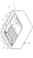
図1は、本実施形態に係る電気音響変換器10を示す側断面図であり、図2は、その分解斜視図である。便宜上、以下の説明では、図1において右方向を「前方」、左方向を「後方」として説明する。
FIG. 1 is a side sectional view showing an
これらの図に示すように、本実施形態に係る電気音響変換器10は、前後方向の長さが5〜8mm程度の略直方体の外形形状を有するバランスドアーマチャ型のレシーバであって、上方に開口するボトムハウジング12と、このボトムハウジング12内に収容された駆動ユニット14と、ボトムハウジング12の上端開口部12aを、ダイヤフラムアッシ16を介して閉塞するトップハウジング18とからなっている。
As shown in these drawings, the
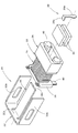
図3は、この電気音響変換器10を、ダイヤフラムアッシ16およびトップハウジング18を外した状態で示す斜視図である。また、図4は、駆動ユニット14をその主要構成要素に分解して示す分解斜視図である。
FIG. 3 is a perspective view showing the
これらの図にも示すように、駆動ユニット14は、アーマチャフレーム20と、ボビン22と、1対のマグネット24と、磁性ホルダ26と、励磁コイル28と、連結片30とからなっている。
As shown in these figures, the
アーマチャフレーム20は、金属板を平面視において略E字状に折曲げ加工してなる部材であって、平面視において前方へ向けて開いたコ字形の鉛直板からなるフレーム32と、このフレーム32の中間部を構成する後面壁32aから前方へ向けて水平に延びる帯板状のアーマチャ34とからなっている。このアーマチャ34は、フレーム32の後面壁32aの中央部において、その略下半部を切り起こすようにして形成されている。
The
ボビン22は、図5に励磁コイル28を外した状態でも示すように、ターミナル保持部36と、コイル巻回部38と、マグネット位置決め部40とが前後方向に直列で配置されてなり、これら各部は樹脂材料の射出成形により一体的に形成されている。
As shown in FIG. 5 with the
ターミナル保持部36は、ボビン22の後端部において鉛直壁状に形成されている。そして、このターミナル保持部36には、上記射出成形の際、金属板からなる左右1対のターミナル42が、その上下両端部を突出させるようにしてインサートされている。また、マグネット位置決め部40には、上記射出成形の際、該マグネット位置決め部40を囲むようにして上記磁性ホルダ26がインサートされている。
The
コイル巻回部38は、前後方向に延びる左右1対の梁部材として構成されており、このコイル巻回部38に導線が所定回数巻回されることにより、上記励磁コイル28が形成されるようになっている。そして、この励磁コイル28の1対のコイル端末28aは、各ターミナル42の上端部42aに巻掛け固定されている。
The
ターミナル保持部36およびマグネット位置決め部40には、コイル巻回部38における両梁部材間の空間と連通するようにして、これらを前後方向に貫通する貫通孔36a、40aが形成されており、これによりアーマチャ34を、ボビン22の後方側から貫通孔36aを介して貫通孔40aの前方側に突出する位置まで前後方向に貫通させるようになっている。そして、マグネット位置決め部40には、その貫通孔40aへ向けて左右両側から階段状に突出する間隙形成部40bが形成されている。
The
磁性ホルダ26は、偏平矩形断面で前後方向に延びる筒状部材であって、磁性体で構成されている。この磁性ホルダ26は、該磁性ホルダ26の上下内壁面とマグネット位置決め部40の間隙形成部40bとで、上記1対のマグネット24を挟持するようになっている。その際、これら1対のマグネット24は、マグネット位置決め部40の貫通孔40a内において上下方向に所定間隙をおいて配置され、両マグネット24により該所定間隙を横断する直流磁界を形成するようになっている。
The
アーマチャフレーム20は、そのアーマチャ34がボビン22の貫通孔36a、40aの略中央を貫通するように位置決めされた状態で、そのフレーム32の左右両面壁32bの前端部において磁性ホルダ26の左右外側面にレーザ溶接等によって固定されている。
The
このとき、アーマチャフレーム20は、そのフレーム32の後面壁32aが、ボビン22のターミナル保持部36と所定間隔をおいて平行に配置されるようになっている。そして、これらフレーム32の後面壁32aとボビン22のターミナル保持部36との間の隙間には、エポキシ系接着剤50が充填されている。このエポキシ系接着剤50は、フレーム32の後面壁32aの略全領域にわたって充填されている。
At this time, the
連結片30は、所定の細長形状に打抜き加工された金属板に折曲げ加工が施されてなる逆L字状部材であって、上下方向に延びるように配置された状態で、その下端部30aにおいてアーマチャ34の先端面34aにレーザ溶接等によって固定されている。このとき、連結片30の上端部30bは、磁性ホルダ26の上方において後方へ向けて水平に延びている。
The connecting
図1および2に示すように、ボトムハウジング12は、略矩形状の上端開口部12aを有する箱形に形成されており、その底面部12bの後端近傍部位には、左右1対の矩形孔12cが形成されている。駆動ユニット14は、このボトムハウジング12内に収容される際、その1対のターミナル42の下端部42bおよびターミナル保持部36の左右下端部に突出形成されたターミナル被覆部36bが矩形孔12cに挿入嵌合され、該矩形孔12cを閉塞するようになっている。そして、駆動ユニット14は、ボトムハウジング12内に収容された状態で、その磁性ホルダ26の下端面においてボトムハウジング12の底面部12bにレーザ溶接等によって固定されている。
As shown in FIGS. 1 and 2, the
このとき、駆動ユニット14は、そのアーマチャフレーム20におけるフレーム32の後面壁32aが、ボトムハウジング12の後面壁12dと所定間隔をおいて平行に配置されるようになっている。
At this time, the
ダイヤフラムアッシ16は、金属製のダイヤフラム44と、PET等からなる樹脂フィルム46と、金属製のダイヤフラムフレーム48とからなり、ダイヤフラムフレーム48内にダイヤフラム44が配置されるとともに両部材44、48の上面に接着剤が塗布された状態で、その上方から樹脂フィルム46が加熱圧着されることにより形成されている。そして、このダイヤフラムアッシ16は、ボトムハウジング12の上端開口部12aに載置された状態で、そのダイヤフラムフレーム48においてボトムハウジング12にレーザ溶接等により固定されている。
The
このダイヤフラムアッシ16がボトムハウジング12の上端開口部12aに載置される際、駆動ユニット14の連結片30の上端部30bが、ダイヤフラム44の下面に当接するようになっており、この状態で連結片30とダイヤフラム44とが接着固定されるようになっている。
When the
トップハウジング18は薄いリッド状部材であって、その前端部には放音孔を構成する切欠き部18aが形成されている。そして、このトップハウジング18は、ダイヤフラムアッシ16に載置された状態で、該ダイヤフラムフレーム48にレーザ溶接等により固定されている。
The
次に、本実施形態に係る電気音響変換器10の動作について説明する。
Next, operation | movement of the
この電気音響変換器10は、その駆動ユニット14における1対のマグネット24間に、この間隙を上下方向に横断する直流磁界が定常的に形成された状態にあるが、外部から励磁コイル28に信号電流が印加されると、この励磁コイル28を貫通するアーマチャ34に信号電流に応じた磁束が発生し、このアーマチャ34と両マグネット24間に交流磁界が形成される。そして、この交流磁界が上記直流磁界に重畳されることにより、信号電流に応じた上下方向の力がアーマチャ34に作用し、これによりアーマチャ34が上下方向に撓み変形する。これに伴い、アーマチャ34の先端面34aに固定された連結片30が、図1に矢印で示すように上下方向に変位し、この上下変位がダイヤフラム44に伝達されて該ダイヤフラム44が振動する。そしてこれにより、信号電流に応じた音波が発生し、この音波が切欠き部18aから電気音響変換器10の外部へ放射される。
The
その際、アーマチャフレーム20におけるフレーム32の後面壁32aとボビン22のターミナル保持部36との間の隙間には、エポキシ系接着剤50がフレーム32の後面壁32aの略全領域にわたって充填されており、このエポキシ系接着剤50によって、フレーム32の後面壁32aはボビン22のターミナル保持部36と接着固定された状態にあるので、上記隙間にエポキシ系接着剤50が充填されていない場合に比して、フレーム32の後面壁32aの剛性を大幅に高めることができる。
At that time, the
このように本実施形態によれば、バランスドアーマチャ型の電気音響変換器10において、これをコンパクトな構成に維持した上で、そのアーマチャ34を片持ち支持するフレーム32の後面壁32aの剛性を大幅に高めることができる。そしてこれによりフレーム32のアーマチャ34に対する支持強度を大幅に高めることができるので、電気音響変換器10の最低共振周波数を大幅に上昇させることができる。具体的には、最低共振周波数を100〜200Hz程度上昇させることができる。
As described above, according to the present embodiment, in the balanced armature
次に、本願発明の第2実施形態について説明する。 Next, a second embodiment of the present invention will be described.
図6は、本実施形態に係る電気音響変換器110を示す側断面図である。
FIG. 6 is a side sectional view showing the
同図に示すように、この電気音響変換器110は、その基本的な構成は上記第1実施形態の場合と全く同様であるが、エポキシ系接着剤50の充填位置が上記第1実施形態の場合と異なっている。
As shown in the figure, the basic configuration of the
すなわち、本実施形態においては、アーマチャフレーム20におけるフレーム32の後面壁32aとボトムハウジング12の後面壁12dとの間の隙間に、エポキシ系接着剤50が充填されている。このエポキシ系接着剤50は、フレーム32の後面壁32aの略全領域にわたって充填されている。
That is, in the present embodiment, the
本実施形態の構成を採用した場合には、エポキシ系接着剤50によって、フレーム32の後面壁32aは、その後方に隣接配置されたボトムハウジング12の後面壁12dと接着固定された状態にあるので、上記隙間にエポキシ系接着剤50が充填されていない場合に比して、フレーム32の後面壁32aの剛性を大幅に高めることができる。
When the configuration of the present embodiment is adopted, the
次に、本願発明の第3実施形態について説明する。 Next, a third embodiment of the present invention will be described.
図7は、本実施形態に係る電気音響変換器210を示す側断面図である。
FIG. 7 is a side sectional view showing the
同図に示すように、この電気音響変換器210は、その基本的な構成は上記第1実施形態の場合と全く同様であるが、エポキシ系接着剤50の充填位置が上記第1実施形態の場合と異なっている。
As shown in the figure, the
すなわち、本実施形態においては、アーマチャフレーム20におけるフレーム32の後面壁32aとボビン22のターミナル保持部36との間の隙間、および、フレーム32の後面壁32aとボトムハウジング12の後面壁12dとの間の隙間に、各々エポキシ系接着剤50が充填されている。このエポキシ系接着剤50は、フレーム32の後面壁32aの前後両面いずれにおいても、その略全領域にわたって充填されている。
That is, in the present embodiment, the gap between the
本実施形態の構成を採用した場合には、エポキシ系接着剤50によって、フレーム32の後面壁32aは、その前後両側に隣接配置されたボビン22のターミナル保持部36およびボトムハウジング12の後面壁12dの双方に接着固定された状態にあるので、上記各隙間にエポキシ系接着剤50が充填されていない場合に比して、フレーム32の後面壁32aの剛性をさらに大幅に高めることができる。
When the configuration of the present embodiment is adopted, the
次に、本願発明の第4実施形態について説明する。 Next, a fourth embodiment of the present invention will be described.
図8は、本実施形態に係る電気音響変換器310を示す側断面図である。
FIG. 8 is a side sectional view showing the
同図に示すように、この電気音響変換器310は、そのエポキシ系接着剤50の充填位置は上記第2実施形態の場合と同様であるが、駆動ユニット14の構成要素としてボビン22を備えていない点で上記第2実施形態の場合と異なっている。
As shown in the figure, the
すなわち、本実施形態においては、励磁コイル28が、その前端面において磁性ホルダ26の後端面に接着固定されている。また、ボトムハウジング12の後面壁12dの外面には、絶縁被膜52を介して1対のランド54が左右方向に所定間隔をおいて設けられている。そして、これら各ランド54には、励磁コイル28から延びる1対のコイル端末28aがハンダ56により導通固定されている。なお、ボトムハウジング12の後面壁12dの上部には、両コイル端末28aを挿通させるための貫通孔(図示せず)が形成されているが、この貫通孔は、フレーム32の後面壁32aとボトムハウジング12の後面壁12dとの間に充填されたエポキシ系接着剤50によって閉塞されるようになっている。
That is, in this embodiment, the
本実施形態の構成を採用した場合にも、上記第2実施形態の場合と同様、エポキシ系接着剤50によって、フレーム32の後面壁32aは、その後方に隣接配置されたボトムハウジング12の後面壁12dと接着固定された状態にあるので、上記隙間にエポキシ系接着剤50が充填されていない場合に比して、フレーム32の後面壁32aの剛性を大幅に高めることができる。
Even in the case of adopting the configuration of the present embodiment, the
次に、本願発明の第5実施形態について説明する。 Next, a fifth embodiment of the present invention will be described.
図9は、本実施形態に係る電気音響変換器410を示す側断面図である。
FIG. 9 is a side sectional view showing the
同図に示すように、この電気音響変換器410は、その基本的な構成およびエポキシ系接着剤50の充填位置は上記第4実施形態の場合と同様であるが、アーマチャフレーム20の構成が上記第4実施形態の場合と異なっている。
As shown in the figure, the
すなわち、本実施形態においては、アーマチャフレーム20を構成するフレーム32とアーマチャ34とが別体で構成されており、アーマチャ34の後端部がフレーム32における後面壁32aの中央部にレーザ溶接等により固定されている。なお、本実施形態においても、ボトムハウジング12の後面壁12dの上部に形成された両コイル端末28aを挿通させるための貫通孔(図示せず)は、フレーム32の後面壁32aとボトムハウジング12の後面壁12dとの間に充填されたエポキシ系接着剤50によって閉塞されるようになっている。
That is, in the present embodiment, the
本実施形態の構成を採用した場合にも、上記第4実施形態の場合と同様、エポキシ系接着剤50によって、フレーム32の後面壁32aは、その後方に隣接配置されたボトムハウジング12の後面壁12dと接着固定された状態にあるので、上記隙間にエポキシ系接着剤50が充填されていない場合に比して、フレーム32の後面壁32aの剛性を大幅に高めることができる。
Even in the case of adopting the configuration of the present embodiment, the
特に本実施形態においては、フレーム32の後面壁12dに、上記第4実施形態のような切り起こし部分がないので、フレーム32自体の剛性を高めることができ、しかも、このフレーム32の後面壁32aとボトムハウジング12の後面壁12dとの接着面積を広く確保することができるので、この点においてもフレーム32の後面壁12dの剛性を高めることができる。
In particular, in the present embodiment, the
なお、上記各実施形態においては、電気音響変換器10の最低共振周波数を最大限に上昇させるため、エポキシ系接着剤50がフレーム32の後面壁32aの略全領域にわたって充填されているものとして説明したが、これによって最低共振周波数が上昇しすぎてしまうような場合には、エポキシ系接着剤50の充填量を減らしたり充填範囲を狭くして、最低共振周波数の上昇量を抑制することも可能である。
In each of the above embodiments, the
また、上記各実施形態においては、エポキシ系接着剤50を用いることにより、フレーム32の後面壁32aとボビン22のターミナル保持部36あるいはボトムハウジング12の後面壁12dとを強固に接着固定するようになっているが、これによって最低共振周波数が上昇しすぎてしまうような場合には、ゴム系接着剤等を用いて接着固定強度を低下させることにより、最低共振周波数の上昇量を抑制することも可能である。
Further, in each of the above embodiments, by using the
10、110、210、310、410 電気音響変換器
12 ボトムハウジング
12a 上端開口部
12b 底面部
12c 矩形孔
12d 後面壁
14 駆動ユニット
16 ダイヤフラムアッシ
18 トップハウジング
18a 切欠き部
20 アーマチャフレーム
22 ボビン
24 マグネット
26 磁性ホルダ
28 励磁コイル
28a コイル端末
30 連結片
30a 下端部
30b 上端部
32 フレーム
32a 後面壁
32b 左右両面壁
34 アーマチャ
36 ターミナル保持部
36a 貫通孔
36b ターミナル被覆部
38 コイル巻回部
40 マグネット位置決め部
40a 貫通孔
40b 間隙形成部
42 ターミナル
42a 上端部
42b 下端部
44 ダイヤフラム
46 樹脂フィルム
48 ダイヤフラムフレーム
50 エポキシ系接着剤
52 絶縁被膜
54 ランド
56 ハンダ
10, 110, 210, 310, 410
Claims (5)
上記駆動ユニットが、所定間隙をおいて対向配置された1対のマグネットと、これらマグネットを保持する磁性ホルダと、この磁性ホルダと隣接する位置に、中心軸が上記両マグネット間を通るように配置された励磁コイルと、この励磁コイルを上記磁性ホルダとは反対側から略コ字状に囲むように配置されるとともに両端部が上記磁性ホルダに固定された金属製のフレームと、上記両マグネット間および上記励磁コイル内を貫通するように配置され、一端部において上記フレームの中間部に固定されるとともに所定部位において連結片を介して上記ダイヤフラムに連結された金属製のアーマチャとを備えてなり、
上記フレームの中間部が、上記ハウジングの周面壁と所定間隔をおいて配置されており、このフレームの中間部と上記ハウジングの周面壁との間の隙間に接着剤が充填されることにより、このフレームの中間部が上記ハウジングの周面壁に固定されている、ことを特徴とする電気音響変換器。 In an electroacoustic transducer in which a diaphragm and a drive unit that vibrates the diaphragm are housed in a housing.
The drive unit is arranged with a pair of magnets facing each other with a predetermined gap, a magnetic holder for holding the magnets, and a central axis passing between the magnets at a position adjacent to the magnetic holder. An excitation coil, a metal frame that is disposed so as to surround the excitation coil in a substantially U shape from the opposite side of the magnetic holder, and both ends are fixed to the magnetic holder, and between the two magnets And a metal armature that is disposed so as to penetrate the inside of the exciting coil, is fixed to an intermediate portion of the frame at one end, and is connected to the diaphragm via a connecting piece at a predetermined portion,
Middle portion of the frame, are arranged at a peripheral wall with a predetermined distance of the housing, the gap adhesive is filled in Rukoto between peripheral wall of the intermediate portion and the housing of the frame, the An electroacoustic transducer, wherein an intermediate portion of the frame is fixed to a peripheral wall of the housing .
上記駆動ユニットが、所定間隙をおいて対向配置された1対のマグネットと、これらマグネットを保持する磁性ホルダと、この磁性ホルダと隣接する位置に、中心軸が上記両マグネット間を通るように配置された励磁コイルと、この励磁コイルを上記磁性ホルダとは反対側から略コ字状に囲むように配置されるとともに両端部が上記磁性ホルダに固定された金属製のフレームと、上記両マグネット間および上記励磁コイル内を貫通するように配置され、一端部において上記フレームの中間部に固定されるとともに所定部位において連結片を介して上記ダイヤフラムに連結された金属製のアーマチャとを備えてなり、
上記励磁コイルが、該励磁コイル内を上記アーマチャと略平行に貫通するように配置されたボビンに支持されており、
このボビンの一端部が、上記フレームの中間部と所定間隔をおいて配置されており、このボビンの一端部と上記フレームの中間部との間の隙間に接着剤が充填されることにより、このボビンの一端部に上記フレームの中間部が固定されている、ことを特徴とする電気音響変換器。 In an electroacoustic transducer in which a diaphragm and a drive unit that vibrates the diaphragm are housed in a housing.
The drive unit is arranged with a pair of magnets facing each other with a predetermined gap, a magnetic holder for holding the magnets, and a central axis passing between the magnets at a position adjacent to the magnetic holder. An excitation coil, a metal frame that is disposed so as to surround the excitation coil in a substantially U shape from the opposite side of the magnetic holder, and both ends are fixed to the magnetic holder, and between the two magnets And a metal armature that is disposed so as to penetrate the inside of the exciting coil, is fixed to an intermediate portion of the frame at one end, and is connected to the diaphragm via a connecting piece at a predetermined portion,
The excitation coil is supported by a bobbin disposed so as to penetrate the excitation coil substantially parallel to the armature;
One end of the bobbin, is disposed at an intermediate portion by a predetermined distance of the frame, by Rukoto adhesive gap is filled between the intermediate portion of the one end portion and the frame of the bobbin, this An electroacoustic transducer, wherein an intermediate portion of the frame is fixed to one end of the bobbin .
Priority Applications (1)
| Application Number | Priority Date | Filing Date | Title |
|---|---|---|---|
| JP2004045937A JP4091006B2 (en) | 2004-02-23 | 2004-02-23 | Electroacoustic transducer |
Applications Claiming Priority (1)
| Application Number | Priority Date | Filing Date | Title |
|---|---|---|---|
| JP2004045937A JP4091006B2 (en) | 2004-02-23 | 2004-02-23 | Electroacoustic transducer |
Publications (2)
| Publication Number | Publication Date |
|---|---|
| JP2005236844A JP2005236844A (en) | 2005-09-02 |
| JP4091006B2 true JP4091006B2 (en) | 2008-05-28 |
Family
ID=35019316
Family Applications (1)
| Application Number | Title | Priority Date | Filing Date |
|---|---|---|---|
| JP2004045937A Expired - Lifetime JP4091006B2 (en) | 2004-02-23 | 2004-02-23 | Electroacoustic transducer |
Country Status (1)
| Country | Link |
|---|---|
| JP (1) | JP4091006B2 (en) |
Families Citing this family (8)
| Publication number | Priority date | Publication date | Assignee | Title |
|---|---|---|---|---|
| DE102005054593B4 (en) * | 2005-11-14 | 2018-04-26 | Immobiliengesellschaft Helmut Fischer Gmbh & Co. Kg | Measuring probe for measuring the thickness of thin layers |
| DK1962551T3 (en) | 2007-02-20 | 2014-07-14 | Sonion Nederland Bv | Sound transmitter with movable luminaire |
| CN201234336Y (en) * | 2008-07-18 | 2009-05-06 | 比亚迪股份有限公司 | Receiver unit |
| DE102008054001B4 (en) * | 2008-10-30 | 2015-12-31 | Knorr-Bremse Systeme für Nutzfahrzeuge GmbH | Pulse speed sensor and method for producing the same |
| CN103024646B (en) * | 2011-09-23 | 2016-08-31 | 苏州恒听电子有限公司 | Conduct vibrations and frequency-selecting amplifying device for moving iron type microphone/transducer |
| JP5886126B2 (en) * | 2012-05-02 | 2016-03-16 | リオン株式会社 | Earphone and listening device using it |
| CN103428590A (en) * | 2012-05-18 | 2013-12-04 | 周巍 | Shielding casing for moving-iron type loudspeaker or receiver |
| CN105282666B (en) * | 2015-08-28 | 2019-01-01 | 国光电器股份有限公司 | Microspeaker |
-
2004
- 2004-02-23 JP JP2004045937A patent/JP4091006B2/en not_active Expired - Lifetime
Also Published As
| Publication number | Publication date |
|---|---|
| JP2005236844A (en) | 2005-09-02 |
Similar Documents
| Publication | Publication Date | Title |
|---|---|---|
| US8588456B2 (en) | Acoustic conversion device | |
| US8634587B2 (en) | Acoustic conversion device | |
| US8630439B2 (en) | Acoustic conversion device and acoustic conversion device assembly method | |
| US8948439B2 (en) | Acoustic conversion device and acoustic conversion device assembly method | |
| EP2961198A2 (en) | Moving coil drive unit and audio drivers incorporating the same | |
| JP6717306B2 (en) | Audio output device | |
| JP4091006B2 (en) | Electroacoustic transducer | |
| JP2006186615A (en) | Electric oscillation transducer | |
| JP3631935B2 (en) | Electroacoustic transducer | |
| JP6014787B1 (en) | Sound generator | |
| EP3352478B1 (en) | Sound production device | |
| KR101154253B1 (en) | Flat type speaker having voice coil plate of three dimensional track type | |
| KR200432596Y1 (en) | A speaker | |
| KR100576266B1 (en) | Plane speaker having double faced voice coil plate | |
| US3313892A (en) | Electromechanical transducers | |
| KR101738135B1 (en) | Balanced armature unit and manufacturing method the same | |
| JP4323177B2 (en) | Vibrator | |
| JP2019092113A (en) | Sound producing device | |
| JP4749347B2 (en) | Electromagnetic transducer | |
| JP6697145B2 (en) | Sounding device | |
| JP2009049757A (en) | Ear-inserted type earphone | |
| JP2005244380A (en) | Electroacoustic transducer | |
| WO2019098181A1 (en) | Sound production device | |
| WO2018034015A1 (en) | Sound generation device and production method therefor | |
| JP2019193080A (en) | Sound production device |
Legal Events
| Date | Code | Title | Description |
|---|---|---|---|
| A621 | Written request for application examination |
Free format text: JAPANESE INTERMEDIATE CODE: A621 Effective date: 20061212 |
|
| A131 | Notification of reasons for refusal |
Free format text: JAPANESE INTERMEDIATE CODE: A131 Effective date: 20071120 |
|
| A521 | Written amendment |
Free format text: JAPANESE INTERMEDIATE CODE: A523 Effective date: 20080121 |
|
| TRDD | Decision of grant or rejection written | ||
| A01 | Written decision to grant a patent or to grant a registration (utility model) |
Free format text: JAPANESE INTERMEDIATE CODE: A01 Effective date: 20080226 |
|
| A61 | First payment of annual fees (during grant procedure) |
Free format text: JAPANESE INTERMEDIATE CODE: A61 Effective date: 20080227 |
|
| R150 | Certificate of patent or registration of utility model |
Free format text: JAPANESE INTERMEDIATE CODE: R150 |
|
| FPAY | Renewal fee payment (event date is renewal date of database) |
Free format text: PAYMENT UNTIL: 20110307 Year of fee payment: 3 |
|
| FPAY | Renewal fee payment (event date is renewal date of database) |
Free format text: PAYMENT UNTIL: 20110307 Year of fee payment: 3 |
|
| FPAY | Renewal fee payment (event date is renewal date of database) |
Free format text: PAYMENT UNTIL: 20120307 Year of fee payment: 4 |
|
| FPAY | Renewal fee payment (event date is renewal date of database) |
Free format text: PAYMENT UNTIL: 20130307 Year of fee payment: 5 |