JP4084835B2 - Flip chip mounting method and inter-board connection method - Google Patents
Flip chip mounting method and inter-board connection method Download PDFInfo
- Publication number
- JP4084835B2 JP4084835B2 JP2007510387A JP2007510387A JP4084835B2 JP 4084835 B2 JP4084835 B2 JP 4084835B2 JP 2007510387 A JP2007510387 A JP 2007510387A JP 2007510387 A JP2007510387 A JP 2007510387A JP 4084835 B2 JP4084835 B2 JP 4084835B2
- Authority
- JP
- Japan
- Prior art keywords
- resin
- substrate
- circuit board
- semiconductor chip
- generating agent
- Prior art date
- Legal status (The legal status is an assumption and is not a legal conclusion. Google has not performed a legal analysis and makes no representation as to the accuracy of the status listed.)
- Expired - Fee Related
Links
Images


Classifications
-
- H—ELECTRICITY
- H01—ELECTRIC ELEMENTS
- H01L—SEMICONDUCTOR DEVICES NOT COVERED BY CLASS H10
- H01L24/00—Arrangements for connecting or disconnecting semiconductor or solid-state bodies; Methods or apparatus related thereto
- H01L24/80—Methods for connecting semiconductor or other solid state bodies using means for bonding being attached to, or being formed on, the surface to be connected
- H01L24/83—Methods for connecting semiconductor or other solid state bodies using means for bonding being attached to, or being formed on, the surface to be connected using a layer connector
-
- H—ELECTRICITY
- H01—ELECTRIC ELEMENTS
- H01L—SEMICONDUCTOR DEVICES NOT COVERED BY CLASS H10
- H01L24/00—Arrangements for connecting or disconnecting semiconductor or solid-state bodies; Methods or apparatus related thereto
- H01L24/01—Means for bonding being attached to, or being formed on, the surface to be connected, e.g. chip-to-package, die-attach, "first-level" interconnects; Manufacturing methods related thereto
- H01L24/10—Bump connectors ; Manufacturing methods related thereto
- H01L24/15—Structure, shape, material or disposition of the bump connectors after the connecting process
- H01L24/16—Structure, shape, material or disposition of the bump connectors after the connecting process of an individual bump connector
-
- H—ELECTRICITY
- H01—ELECTRIC ELEMENTS
- H01L—SEMICONDUCTOR DEVICES NOT COVERED BY CLASS H10
- H01L24/00—Arrangements for connecting or disconnecting semiconductor or solid-state bodies; Methods or apparatus related thereto
- H01L24/01—Means for bonding being attached to, or being formed on, the surface to be connected, e.g. chip-to-package, die-attach, "first-level" interconnects; Manufacturing methods related thereto
- H01L24/26—Layer connectors, e.g. plate connectors, solder or adhesive layers; Manufacturing methods related thereto
- H01L24/28—Structure, shape, material or disposition of the layer connectors prior to the connecting process
- H01L24/29—Structure, shape, material or disposition of the layer connectors prior to the connecting process of an individual layer connector
-
- H—ELECTRICITY
- H05—ELECTRIC TECHNIQUES NOT OTHERWISE PROVIDED FOR
- H05K—PRINTED CIRCUITS; CASINGS OR CONSTRUCTIONAL DETAILS OF ELECTRIC APPARATUS; MANUFACTURE OF ASSEMBLAGES OF ELECTRICAL COMPONENTS
- H05K3/00—Apparatus or processes for manufacturing printed circuits
- H05K3/30—Assembling printed circuits with electric components, e.g. with resistor
- H05K3/32—Assembling printed circuits with electric components, e.g. with resistor electrically connecting electric components or wires to printed circuits
- H05K3/321—Assembling printed circuits with electric components, e.g. with resistor electrically connecting electric components or wires to printed circuits by conductive adhesives
- H05K3/323—Assembling printed circuits with electric components, e.g. with resistor electrically connecting electric components or wires to printed circuits by conductive adhesives by applying an anisotropic conductive adhesive layer over an array of pads
-
- H—ELECTRICITY
- H01—ELECTRIC ELEMENTS
- H01L—SEMICONDUCTOR DEVICES NOT COVERED BY CLASS H10
- H01L21/00—Processes or apparatus adapted for the manufacture or treatment of semiconductor or solid state devices or of parts thereof
- H01L21/02—Manufacture or treatment of semiconductor devices or of parts thereof
- H01L21/04—Manufacture or treatment of semiconductor devices or of parts thereof the devices having at least one potential-jump barrier or surface barrier, e.g. PN junction, depletion layer or carrier concentration layer
- H01L21/50—Assembly of semiconductor devices using processes or apparatus not provided for in a single one of the subgroups H01L21/06 - H01L21/326, e.g. sealing of a cap to a base of a container
- H01L21/56—Encapsulations, e.g. encapsulation layers, coatings
- H01L21/563—Encapsulation of active face of flip-chip device, e.g. underfilling or underencapsulation of flip-chip, encapsulation preform on chip or mounting substrate
-
- H—ELECTRICITY
- H01—ELECTRIC ELEMENTS
- H01L—SEMICONDUCTOR DEVICES NOT COVERED BY CLASS H10
- H01L2224/00—Indexing scheme for arrangements for connecting or disconnecting semiconductor or solid-state bodies and methods related thereto as covered by H01L24/00
- H01L2224/01—Means for bonding being attached to, or being formed on, the surface to be connected, e.g. chip-to-package, die-attach, "first-level" interconnects; Manufacturing methods related thereto
- H01L2224/10—Bump connectors; Manufacturing methods related thereto
- H01L2224/12—Structure, shape, material or disposition of the bump connectors prior to the connecting process
- H01L2224/13—Structure, shape, material or disposition of the bump connectors prior to the connecting process of an individual bump connector
- H01L2224/13001—Core members of the bump connector
- H01L2224/13099—Material
- H01L2224/1319—Material with a principal constituent of the material being a polymer, e.g. polyester, phenolic based polymer, epoxy
-
- H—ELECTRICITY
- H01—ELECTRIC ELEMENTS
- H01L—SEMICONDUCTOR DEVICES NOT COVERED BY CLASS H10
- H01L2224/00—Indexing scheme for arrangements for connecting or disconnecting semiconductor or solid-state bodies and methods related thereto as covered by H01L24/00
- H01L2224/01—Means for bonding being attached to, or being formed on, the surface to be connected, e.g. chip-to-package, die-attach, "first-level" interconnects; Manufacturing methods related thereto
- H01L2224/10—Bump connectors; Manufacturing methods related thereto
- H01L2224/12—Structure, shape, material or disposition of the bump connectors prior to the connecting process
- H01L2224/13—Structure, shape, material or disposition of the bump connectors prior to the connecting process of an individual bump connector
- H01L2224/13001—Core members of the bump connector
- H01L2224/13099—Material
- H01L2224/13198—Material with a principal constituent of the material being a combination of two or more materials in the form of a matrix with a filler, i.e. being a hybrid material, e.g. segmented structures, foams
- H01L2224/13199—Material of the matrix
- H01L2224/1329—Material of the matrix with a principal constituent of the material being a polymer, e.g. polyester, phenolic based polymer, epoxy
-
- H—ELECTRICITY
- H01—ELECTRIC ELEMENTS
- H01L—SEMICONDUCTOR DEVICES NOT COVERED BY CLASS H10
- H01L2224/00—Indexing scheme for arrangements for connecting or disconnecting semiconductor or solid-state bodies and methods related thereto as covered by H01L24/00
- H01L2224/01—Means for bonding being attached to, or being formed on, the surface to be connected, e.g. chip-to-package, die-attach, "first-level" interconnects; Manufacturing methods related thereto
- H01L2224/10—Bump connectors; Manufacturing methods related thereto
- H01L2224/12—Structure, shape, material or disposition of the bump connectors prior to the connecting process
- H01L2224/13—Structure, shape, material or disposition of the bump connectors prior to the connecting process of an individual bump connector
- H01L2224/13001—Core members of the bump connector
- H01L2224/13099—Material
- H01L2224/13198—Material with a principal constituent of the material being a combination of two or more materials in the form of a matrix with a filler, i.e. being a hybrid material, e.g. segmented structures, foams
- H01L2224/13298—Fillers
- H01L2224/13299—Base material
- H01L2224/133—Base material with a principal constituent of the material being a metal or a metalloid, e.g. boron [B], silicon [Si], germanium [Ge], arsenic [As], antimony [Sb], tellurium [Te] and polonium [Po], and alloys thereof
- H01L2224/13338—Base material with a principal constituent of the material being a metal or a metalloid, e.g. boron [B], silicon [Si], germanium [Ge], arsenic [As], antimony [Sb], tellurium [Te] and polonium [Po], and alloys thereof the principal constituent melting at a temperature of greater than or equal to 950°C and less than 1550°C
- H01L2224/13339—Silver [Ag] as principal constituent
-
- H—ELECTRICITY
- H01—ELECTRIC ELEMENTS
- H01L—SEMICONDUCTOR DEVICES NOT COVERED BY CLASS H10
- H01L2224/00—Indexing scheme for arrangements for connecting or disconnecting semiconductor or solid-state bodies and methods related thereto as covered by H01L24/00
- H01L2224/01—Means for bonding being attached to, or being formed on, the surface to be connected, e.g. chip-to-package, die-attach, "first-level" interconnects; Manufacturing methods related thereto
- H01L2224/10—Bump connectors; Manufacturing methods related thereto
- H01L2224/12—Structure, shape, material or disposition of the bump connectors prior to the connecting process
- H01L2224/13—Structure, shape, material or disposition of the bump connectors prior to the connecting process of an individual bump connector
- H01L2224/13001—Core members of the bump connector
- H01L2224/13099—Material
- H01L2224/13198—Material with a principal constituent of the material being a combination of two or more materials in the form of a matrix with a filler, i.e. being a hybrid material, e.g. segmented structures, foams
- H01L2224/13298—Fillers
- H01L2224/13299—Base material
- H01L2224/133—Base material with a principal constituent of the material being a metal or a metalloid, e.g. boron [B], silicon [Si], germanium [Ge], arsenic [As], antimony [Sb], tellurium [Te] and polonium [Po], and alloys thereof
- H01L2224/13338—Base material with a principal constituent of the material being a metal or a metalloid, e.g. boron [B], silicon [Si], germanium [Ge], arsenic [As], antimony [Sb], tellurium [Te] and polonium [Po], and alloys thereof the principal constituent melting at a temperature of greater than or equal to 950°C and less than 1550°C
- H01L2224/13347—Copper [Cu] as principal constituent
-
- H—ELECTRICITY
- H01—ELECTRIC ELEMENTS
- H01L—SEMICONDUCTOR DEVICES NOT COVERED BY CLASS H10
- H01L2224/00—Indexing scheme for arrangements for connecting or disconnecting semiconductor or solid-state bodies and methods related thereto as covered by H01L24/00
- H01L2224/01—Means for bonding being attached to, or being formed on, the surface to be connected, e.g. chip-to-package, die-attach, "first-level" interconnects; Manufacturing methods related thereto
- H01L2224/10—Bump connectors; Manufacturing methods related thereto
- H01L2224/15—Structure, shape, material or disposition of the bump connectors after the connecting process
- H01L2224/16—Structure, shape, material or disposition of the bump connectors after the connecting process of an individual bump connector
- H01L2224/161—Disposition
- H01L2224/16135—Disposition the bump connector connecting between different semiconductor or solid-state bodies, i.e. chip-to-chip
- H01L2224/16145—Disposition the bump connector connecting between different semiconductor or solid-state bodies, i.e. chip-to-chip the bodies being stacked
- H01L2224/16148—Disposition the bump connector connecting between different semiconductor or solid-state bodies, i.e. chip-to-chip the bodies being stacked the bump connector connecting to a bonding area protruding from the surface
-
- H—ELECTRICITY
- H01—ELECTRIC ELEMENTS
- H01L—SEMICONDUCTOR DEVICES NOT COVERED BY CLASS H10
- H01L2224/00—Indexing scheme for arrangements for connecting or disconnecting semiconductor or solid-state bodies and methods related thereto as covered by H01L24/00
- H01L2224/01—Means for bonding being attached to, or being formed on, the surface to be connected, e.g. chip-to-package, die-attach, "first-level" interconnects; Manufacturing methods related thereto
- H01L2224/10—Bump connectors; Manufacturing methods related thereto
- H01L2224/15—Structure, shape, material or disposition of the bump connectors after the connecting process
- H01L2224/16—Structure, shape, material or disposition of the bump connectors after the connecting process of an individual bump connector
- H01L2224/161—Disposition
- H01L2224/16151—Disposition the bump connector connecting between a semiconductor or solid-state body and an item not being a semiconductor or solid-state body, e.g. chip-to-substrate, chip-to-passive
- H01L2224/16221—Disposition the bump connector connecting between a semiconductor or solid-state body and an item not being a semiconductor or solid-state body, e.g. chip-to-substrate, chip-to-passive the body and the item being stacked
- H01L2224/16225—Disposition the bump connector connecting between a semiconductor or solid-state body and an item not being a semiconductor or solid-state body, e.g. chip-to-substrate, chip-to-passive the body and the item being stacked the item being non-metallic, e.g. insulating substrate with or without metallisation
- H01L2224/16227—Disposition the bump connector connecting between a semiconductor or solid-state body and an item not being a semiconductor or solid-state body, e.g. chip-to-substrate, chip-to-passive the body and the item being stacked the item being non-metallic, e.g. insulating substrate with or without metallisation the bump connector connecting to a bond pad of the item
-
- H—ELECTRICITY
- H01—ELECTRIC ELEMENTS
- H01L—SEMICONDUCTOR DEVICES NOT COVERED BY CLASS H10
- H01L2224/00—Indexing scheme for arrangements for connecting or disconnecting semiconductor or solid-state bodies and methods related thereto as covered by H01L24/00
- H01L2224/01—Means for bonding being attached to, or being formed on, the surface to be connected, e.g. chip-to-package, die-attach, "first-level" interconnects; Manufacturing methods related thereto
- H01L2224/10—Bump connectors; Manufacturing methods related thereto
- H01L2224/15—Structure, shape, material or disposition of the bump connectors after the connecting process
- H01L2224/16—Structure, shape, material or disposition of the bump connectors after the connecting process of an individual bump connector
- H01L2224/165—Material
-
- H—ELECTRICITY
- H01—ELECTRIC ELEMENTS
- H01L—SEMICONDUCTOR DEVICES NOT COVERED BY CLASS H10
- H01L2224/00—Indexing scheme for arrangements for connecting or disconnecting semiconductor or solid-state bodies and methods related thereto as covered by H01L24/00
- H01L2224/01—Means for bonding being attached to, or being formed on, the surface to be connected, e.g. chip-to-package, die-attach, "first-level" interconnects; Manufacturing methods related thereto
- H01L2224/26—Layer connectors, e.g. plate connectors, solder or adhesive layers; Manufacturing methods related thereto
- H01L2224/28—Structure, shape, material or disposition of the layer connectors prior to the connecting process
- H01L2224/29—Structure, shape, material or disposition of the layer connectors prior to the connecting process of an individual layer connector
- H01L2224/29001—Core members of the layer connector
- H01L2224/29099—Material
- H01L2224/291—Material with a principal constituent of the material being a metal or a metalloid, e.g. boron [B], silicon [Si], germanium [Ge], arsenic [As], antimony [Sb], tellurium [Te] and polonium [Po], and alloys thereof
- H01L2224/29101—Material with a principal constituent of the material being a metal or a metalloid, e.g. boron [B], silicon [Si], germanium [Ge], arsenic [As], antimony [Sb], tellurium [Te] and polonium [Po], and alloys thereof the principal constituent melting at a temperature of less than 400°C
- H01L2224/29111—Tin [Sn] as principal constituent
-
- H—ELECTRICITY
- H01—ELECTRIC ELEMENTS
- H01L—SEMICONDUCTOR DEVICES NOT COVERED BY CLASS H10
- H01L2224/00—Indexing scheme for arrangements for connecting or disconnecting semiconductor or solid-state bodies and methods related thereto as covered by H01L24/00
- H01L2224/01—Means for bonding being attached to, or being formed on, the surface to be connected, e.g. chip-to-package, die-attach, "first-level" interconnects; Manufacturing methods related thereto
- H01L2224/26—Layer connectors, e.g. plate connectors, solder or adhesive layers; Manufacturing methods related thereto
- H01L2224/28—Structure, shape, material or disposition of the layer connectors prior to the connecting process
- H01L2224/29—Structure, shape, material or disposition of the layer connectors prior to the connecting process of an individual layer connector
- H01L2224/29001—Core members of the layer connector
- H01L2224/29099—Material
- H01L2224/2919—Material with a principal constituent of the material being a polymer, e.g. polyester, phenolic based polymer, epoxy
-
- H—ELECTRICITY
- H01—ELECTRIC ELEMENTS
- H01L—SEMICONDUCTOR DEVICES NOT COVERED BY CLASS H10
- H01L2224/00—Indexing scheme for arrangements for connecting or disconnecting semiconductor or solid-state bodies and methods related thereto as covered by H01L24/00
- H01L2224/01—Means for bonding being attached to, or being formed on, the surface to be connected, e.g. chip-to-package, die-attach, "first-level" interconnects; Manufacturing methods related thereto
- H01L2224/26—Layer connectors, e.g. plate connectors, solder or adhesive layers; Manufacturing methods related thereto
- H01L2224/28—Structure, shape, material or disposition of the layer connectors prior to the connecting process
- H01L2224/29—Structure, shape, material or disposition of the layer connectors prior to the connecting process of an individual layer connector
- H01L2224/29001—Core members of the layer connector
- H01L2224/29099—Material
- H01L2224/29198—Material with a principal constituent of the material being a combination of two or more materials in the form of a matrix with a filler, i.e. being a hybrid material, e.g. segmented structures, foams
- H01L2224/29199—Material of the matrix
- H01L2224/2929—Material of the matrix with a principal constituent of the material being a polymer, e.g. polyester, phenolic based polymer, epoxy
- H01L2224/29291—The principal constituent being an elastomer, e.g. silicones, isoprene, neoprene
-
- H—ELECTRICITY
- H01—ELECTRIC ELEMENTS
- H01L—SEMICONDUCTOR DEVICES NOT COVERED BY CLASS H10
- H01L2224/00—Indexing scheme for arrangements for connecting or disconnecting semiconductor or solid-state bodies and methods related thereto as covered by H01L24/00
- H01L2224/01—Means for bonding being attached to, or being formed on, the surface to be connected, e.g. chip-to-package, die-attach, "first-level" interconnects; Manufacturing methods related thereto
- H01L2224/26—Layer connectors, e.g. plate connectors, solder or adhesive layers; Manufacturing methods related thereto
- H01L2224/28—Structure, shape, material or disposition of the layer connectors prior to the connecting process
- H01L2224/29—Structure, shape, material or disposition of the layer connectors prior to the connecting process of an individual layer connector
- H01L2224/29001—Core members of the layer connector
- H01L2224/29099—Material
- H01L2224/29198—Material with a principal constituent of the material being a combination of two or more materials in the form of a matrix with a filler, i.e. being a hybrid material, e.g. segmented structures, foams
- H01L2224/29298—Fillers
- H01L2224/29299—Base material
- H01L2224/293—Base material with a principal constituent of the material being a metal or a metalloid, e.g. boron [B], silicon [Si], germanium [Ge], arsenic [As], antimony [Sb], tellurium [Te] and polonium [Po], and alloys thereof
- H01L2224/29338—Base material with a principal constituent of the material being a metal or a metalloid, e.g. boron [B], silicon [Si], germanium [Ge], arsenic [As], antimony [Sb], tellurium [Te] and polonium [Po], and alloys thereof the principal constituent melting at a temperature of greater than or equal to 950°C and less than 1550°C
- H01L2224/29339—Silver [Ag] as principal constituent
-
- H—ELECTRICITY
- H01—ELECTRIC ELEMENTS
- H01L—SEMICONDUCTOR DEVICES NOT COVERED BY CLASS H10
- H01L2224/00—Indexing scheme for arrangements for connecting or disconnecting semiconductor or solid-state bodies and methods related thereto as covered by H01L24/00
- H01L2224/01—Means for bonding being attached to, or being formed on, the surface to be connected, e.g. chip-to-package, die-attach, "first-level" interconnects; Manufacturing methods related thereto
- H01L2224/26—Layer connectors, e.g. plate connectors, solder or adhesive layers; Manufacturing methods related thereto
- H01L2224/28—Structure, shape, material or disposition of the layer connectors prior to the connecting process
- H01L2224/29—Structure, shape, material or disposition of the layer connectors prior to the connecting process of an individual layer connector
- H01L2224/29001—Core members of the layer connector
- H01L2224/29099—Material
- H01L2224/29198—Material with a principal constituent of the material being a combination of two or more materials in the form of a matrix with a filler, i.e. being a hybrid material, e.g. segmented structures, foams
- H01L2224/29298—Fillers
- H01L2224/29299—Base material
- H01L2224/293—Base material with a principal constituent of the material being a metal or a metalloid, e.g. boron [B], silicon [Si], germanium [Ge], arsenic [As], antimony [Sb], tellurium [Te] and polonium [Po], and alloys thereof
- H01L2224/29338—Base material with a principal constituent of the material being a metal or a metalloid, e.g. boron [B], silicon [Si], germanium [Ge], arsenic [As], antimony [Sb], tellurium [Te] and polonium [Po], and alloys thereof the principal constituent melting at a temperature of greater than or equal to 950°C and less than 1550°C
- H01L2224/29347—Copper [Cu] as principal constituent
-
- H—ELECTRICITY
- H01—ELECTRIC ELEMENTS
- H01L—SEMICONDUCTOR DEVICES NOT COVERED BY CLASS H10
- H01L2224/00—Indexing scheme for arrangements for connecting or disconnecting semiconductor or solid-state bodies and methods related thereto as covered by H01L24/00
- H01L2224/73—Means for bonding being of different types provided for in two or more of groups H01L2224/10, H01L2224/18, H01L2224/26, H01L2224/34, H01L2224/42, H01L2224/50, H01L2224/63, H01L2224/71
- H01L2224/732—Location after the connecting process
- H01L2224/73201—Location after the connecting process on the same surface
- H01L2224/73203—Bump and layer connectors
- H01L2224/73204—Bump and layer connectors the bump connector being embedded into the layer connector
-
- H—ELECTRICITY
- H01—ELECTRIC ELEMENTS
- H01L—SEMICONDUCTOR DEVICES NOT COVERED BY CLASS H10
- H01L2224/00—Indexing scheme for arrangements for connecting or disconnecting semiconductor or solid-state bodies and methods related thereto as covered by H01L24/00
- H01L2224/74—Apparatus for manufacturing arrangements for connecting or disconnecting semiconductor or solid-state bodies and for methods related thereto
- H01L2224/75—Apparatus for connecting with bump connectors or layer connectors
-
- H—ELECTRICITY
- H01—ELECTRIC ELEMENTS
- H01L—SEMICONDUCTOR DEVICES NOT COVERED BY CLASS H10
- H01L2224/00—Indexing scheme for arrangements for connecting or disconnecting semiconductor or solid-state bodies and methods related thereto as covered by H01L24/00
- H01L2224/80—Methods for connecting semiconductor or other solid state bodies using means for bonding being attached to, or being formed on, the surface to be connected
- H01L2224/83—Methods for connecting semiconductor or other solid state bodies using means for bonding being attached to, or being formed on, the surface to be connected using a layer connector
- H01L2224/83009—Pre-treatment of the layer connector or the bonding area
- H01L2224/8303—Reshaping the layer connector in the bonding apparatus, e.g. flattening the layer connector
- H01L2224/83047—Reshaping the layer connector in the bonding apparatus, e.g. flattening the layer connector by mechanical means, e.g. severing, pressing, stamping
-
- H—ELECTRICITY
- H01—ELECTRIC ELEMENTS
- H01L—SEMICONDUCTOR DEVICES NOT COVERED BY CLASS H10
- H01L2224/00—Indexing scheme for arrangements for connecting or disconnecting semiconductor or solid-state bodies and methods related thereto as covered by H01L24/00
- H01L2224/80—Methods for connecting semiconductor or other solid state bodies using means for bonding being attached to, or being formed on, the surface to be connected
- H01L2224/83—Methods for connecting semiconductor or other solid state bodies using means for bonding being attached to, or being formed on, the surface to be connected using a layer connector
- H01L2224/83053—Bonding environment
- H01L2224/83091—Under pressure
-
- H—ELECTRICITY
- H01—ELECTRIC ELEMENTS
- H01L—SEMICONDUCTOR DEVICES NOT COVERED BY CLASS H10
- H01L2224/00—Indexing scheme for arrangements for connecting or disconnecting semiconductor or solid-state bodies and methods related thereto as covered by H01L24/00
- H01L2224/80—Methods for connecting semiconductor or other solid state bodies using means for bonding being attached to, or being formed on, the surface to be connected
- H01L2224/83—Methods for connecting semiconductor or other solid state bodies using means for bonding being attached to, or being formed on, the surface to be connected using a layer connector
- H01L2224/83053—Bonding environment
- H01L2224/83095—Temperature settings
- H01L2224/83096—Transient conditions
- H01L2224/83097—Heating
-
- H—ELECTRICITY
- H01—ELECTRIC ELEMENTS
- H01L—SEMICONDUCTOR DEVICES NOT COVERED BY CLASS H10
- H01L2224/00—Indexing scheme for arrangements for connecting or disconnecting semiconductor or solid-state bodies and methods related thereto as covered by H01L24/00
- H01L2224/80—Methods for connecting semiconductor or other solid state bodies using means for bonding being attached to, or being formed on, the surface to be connected
- H01L2224/83—Methods for connecting semiconductor or other solid state bodies using means for bonding being attached to, or being formed on, the surface to be connected using a layer connector
- H01L2224/8319—Arrangement of the layer connectors prior to mounting
- H01L2224/83192—Arrangement of the layer connectors prior to mounting wherein the layer connectors are disposed only on another item or body to be connected to the semiconductor or solid-state body
-
- H—ELECTRICITY
- H01—ELECTRIC ELEMENTS
- H01L—SEMICONDUCTOR DEVICES NOT COVERED BY CLASS H10
- H01L2224/00—Indexing scheme for arrangements for connecting or disconnecting semiconductor or solid-state bodies and methods related thereto as covered by H01L24/00
- H01L2224/80—Methods for connecting semiconductor or other solid state bodies using means for bonding being attached to, or being formed on, the surface to be connected
- H01L2224/83—Methods for connecting semiconductor or other solid state bodies using means for bonding being attached to, or being formed on, the surface to be connected using a layer connector
- H01L2224/832—Applying energy for connecting
- H01L2224/83201—Compression bonding
- H01L2224/83203—Thermocompression bonding, e.g. diffusion bonding, pressure joining, thermocompression welding or solid-state welding
- H01L2224/83204—Thermocompression bonding, e.g. diffusion bonding, pressure joining, thermocompression welding or solid-state welding with a graded temperature profile
-
- H—ELECTRICITY
- H01—ELECTRIC ELEMENTS
- H01L—SEMICONDUCTOR DEVICES NOT COVERED BY CLASS H10
- H01L2224/00—Indexing scheme for arrangements for connecting or disconnecting semiconductor or solid-state bodies and methods related thereto as covered by H01L24/00
- H01L2224/80—Methods for connecting semiconductor or other solid state bodies using means for bonding being attached to, or being formed on, the surface to be connected
- H01L2224/83—Methods for connecting semiconductor or other solid state bodies using means for bonding being attached to, or being formed on, the surface to be connected using a layer connector
- H01L2224/838—Bonding techniques
- H01L2224/8385—Bonding techniques using a polymer adhesive, e.g. an adhesive based on silicone, epoxy, polyimide, polyester
- H01L2224/83855—Hardening the adhesive by curing, i.e. thermosetting
- H01L2224/83862—Heat curing
-
- H—ELECTRICITY
- H01—ELECTRIC ELEMENTS
- H01L—SEMICONDUCTOR DEVICES NOT COVERED BY CLASS H10
- H01L2224/00—Indexing scheme for arrangements for connecting or disconnecting semiconductor or solid-state bodies and methods related thereto as covered by H01L24/00
- H01L2224/80—Methods for connecting semiconductor or other solid state bodies using means for bonding being attached to, or being formed on, the surface to be connected
- H01L2224/83—Methods for connecting semiconductor or other solid state bodies using means for bonding being attached to, or being formed on, the surface to be connected using a layer connector
- H01L2224/838—Bonding techniques
- H01L2224/8385—Bonding techniques using a polymer adhesive, e.g. an adhesive based on silicone, epoxy, polyimide, polyester
- H01L2224/8388—Hardening the adhesive by cooling, e.g. for thermoplastics or hot-melt adhesives
-
- H—ELECTRICITY
- H01—ELECTRIC ELEMENTS
- H01L—SEMICONDUCTOR DEVICES NOT COVERED BY CLASS H10
- H01L2224/00—Indexing scheme for arrangements for connecting or disconnecting semiconductor or solid-state bodies and methods related thereto as covered by H01L24/00
- H01L2224/80—Methods for connecting semiconductor or other solid state bodies using means for bonding being attached to, or being formed on, the surface to be connected
- H01L2224/83—Methods for connecting semiconductor or other solid state bodies using means for bonding being attached to, or being formed on, the surface to be connected using a layer connector
- H01L2224/838—Bonding techniques
- H01L2224/83886—Involving a self-assembly process, e.g. self-agglomeration of a material dispersed in a fluid
- H01L2224/83887—Auxiliary means therefor, e.g. for self-assembly activation
-
- H—ELECTRICITY
- H01—ELECTRIC ELEMENTS
- H01L—SEMICONDUCTOR DEVICES NOT COVERED BY CLASS H10
- H01L2225/00—Details relating to assemblies covered by the group H01L25/00 but not provided for in its subgroups
- H01L2225/03—All the devices being of a type provided for in the same subgroup of groups H01L27/00 - H01L33/648 and H10K99/00
- H01L2225/04—All the devices being of a type provided for in the same subgroup of groups H01L27/00 - H01L33/648 and H10K99/00 the devices not having separate containers
- H01L2225/065—All the devices being of a type provided for in the same subgroup of groups H01L27/00 - H01L33/648 and H10K99/00 the devices not having separate containers the devices being of a type provided for in group H01L27/00
- H01L2225/06503—Stacked arrangements of devices
- H01L2225/06513—Bump or bump-like direct electrical connections between devices, e.g. flip-chip connection, solder bumps
-
- H—ELECTRICITY
- H01—ELECTRIC ELEMENTS
- H01L—SEMICONDUCTOR DEVICES NOT COVERED BY CLASS H10
- H01L24/00—Arrangements for connecting or disconnecting semiconductor or solid-state bodies; Methods or apparatus related thereto
- H01L24/01—Means for bonding being attached to, or being formed on, the surface to be connected, e.g. chip-to-package, die-attach, "first-level" interconnects; Manufacturing methods related thereto
- H01L24/26—Layer connectors, e.g. plate connectors, solder or adhesive layers; Manufacturing methods related thereto
- H01L24/27—Manufacturing methods
-
- H—ELECTRICITY
- H01—ELECTRIC ELEMENTS
- H01L—SEMICONDUCTOR DEVICES NOT COVERED BY CLASS H10
- H01L24/00—Arrangements for connecting or disconnecting semiconductor or solid-state bodies; Methods or apparatus related thereto
- H01L24/73—Means for bonding being of different types provided for in two or more of groups H01L24/10, H01L24/18, H01L24/26, H01L24/34, H01L24/42, H01L24/50, H01L24/63, H01L24/71
-
- H—ELECTRICITY
- H01—ELECTRIC ELEMENTS
- H01L—SEMICONDUCTOR DEVICES NOT COVERED BY CLASS H10
- H01L25/00—Assemblies consisting of a plurality of individual semiconductor or other solid state devices ; Multistep manufacturing processes thereof
- H01L25/03—Assemblies consisting of a plurality of individual semiconductor or other solid state devices ; Multistep manufacturing processes thereof all the devices being of a type provided for in the same subgroup of groups H01L27/00 - H01L33/00, or in a single subclass of H10K, H10N, e.g. assemblies of rectifier diodes
- H01L25/04—Assemblies consisting of a plurality of individual semiconductor or other solid state devices ; Multistep manufacturing processes thereof all the devices being of a type provided for in the same subgroup of groups H01L27/00 - H01L33/00, or in a single subclass of H10K, H10N, e.g. assemblies of rectifier diodes the devices not having separate containers
- H01L25/065—Assemblies consisting of a plurality of individual semiconductor or other solid state devices ; Multistep manufacturing processes thereof all the devices being of a type provided for in the same subgroup of groups H01L27/00 - H01L33/00, or in a single subclass of H10K, H10N, e.g. assemblies of rectifier diodes the devices not having separate containers the devices being of a type provided for in group H01L27/00
- H01L25/0657—Stacked arrangements of devices
-
- H—ELECTRICITY
- H01—ELECTRIC ELEMENTS
- H01L—SEMICONDUCTOR DEVICES NOT COVERED BY CLASS H10
- H01L25/00—Assemblies consisting of a plurality of individual semiconductor or other solid state devices ; Multistep manufacturing processes thereof
- H01L25/50—Multistep manufacturing processes of assemblies consisting of devices, each device being of a type provided for in group H01L27/00 or H01L29/00
-
- H—ELECTRICITY
- H01—ELECTRIC ELEMENTS
- H01L—SEMICONDUCTOR DEVICES NOT COVERED BY CLASS H10
- H01L2924/00—Indexing scheme for arrangements or methods for connecting or disconnecting semiconductor or solid-state bodies as covered by H01L24/00
- H01L2924/01—Chemical elements
- H01L2924/01002—Helium [He]
-
- H—ELECTRICITY
- H01—ELECTRIC ELEMENTS
- H01L—SEMICONDUCTOR DEVICES NOT COVERED BY CLASS H10
- H01L2924/00—Indexing scheme for arrangements or methods for connecting or disconnecting semiconductor or solid-state bodies as covered by H01L24/00
- H01L2924/01—Chemical elements
- H01L2924/01004—Beryllium [Be]
-
- H—ELECTRICITY
- H01—ELECTRIC ELEMENTS
- H01L—SEMICONDUCTOR DEVICES NOT COVERED BY CLASS H10
- H01L2924/00—Indexing scheme for arrangements or methods for connecting or disconnecting semiconductor or solid-state bodies as covered by H01L24/00
- H01L2924/01—Chemical elements
- H01L2924/01005—Boron [B]
-
- H—ELECTRICITY
- H01—ELECTRIC ELEMENTS
- H01L—SEMICONDUCTOR DEVICES NOT COVERED BY CLASS H10
- H01L2924/00—Indexing scheme for arrangements or methods for connecting or disconnecting semiconductor or solid-state bodies as covered by H01L24/00
- H01L2924/01—Chemical elements
- H01L2924/01006—Carbon [C]
-
- H—ELECTRICITY
- H01—ELECTRIC ELEMENTS
- H01L—SEMICONDUCTOR DEVICES NOT COVERED BY CLASS H10
- H01L2924/00—Indexing scheme for arrangements or methods for connecting or disconnecting semiconductor or solid-state bodies as covered by H01L24/00
- H01L2924/01—Chemical elements
- H01L2924/01009—Fluorine [F]
-
- H—ELECTRICITY
- H01—ELECTRIC ELEMENTS
- H01L—SEMICONDUCTOR DEVICES NOT COVERED BY CLASS H10
- H01L2924/00—Indexing scheme for arrangements or methods for connecting or disconnecting semiconductor or solid-state bodies as covered by H01L24/00
- H01L2924/01—Chemical elements
- H01L2924/01013—Aluminum [Al]
-
- H—ELECTRICITY
- H01—ELECTRIC ELEMENTS
- H01L—SEMICONDUCTOR DEVICES NOT COVERED BY CLASS H10
- H01L2924/00—Indexing scheme for arrangements or methods for connecting or disconnecting semiconductor or solid-state bodies as covered by H01L24/00
- H01L2924/01—Chemical elements
- H01L2924/01015—Phosphorus [P]
-
- H—ELECTRICITY
- H01—ELECTRIC ELEMENTS
- H01L—SEMICONDUCTOR DEVICES NOT COVERED BY CLASS H10
- H01L2924/00—Indexing scheme for arrangements or methods for connecting or disconnecting semiconductor or solid-state bodies as covered by H01L24/00
- H01L2924/01—Chemical elements
- H01L2924/01019—Potassium [K]
-
- H—ELECTRICITY
- H01—ELECTRIC ELEMENTS
- H01L—SEMICONDUCTOR DEVICES NOT COVERED BY CLASS H10
- H01L2924/00—Indexing scheme for arrangements or methods for connecting or disconnecting semiconductor or solid-state bodies as covered by H01L24/00
- H01L2924/01—Chemical elements
- H01L2924/01027—Cobalt [Co]
-
- H—ELECTRICITY
- H01—ELECTRIC ELEMENTS
- H01L—SEMICONDUCTOR DEVICES NOT COVERED BY CLASS H10
- H01L2924/00—Indexing scheme for arrangements or methods for connecting or disconnecting semiconductor or solid-state bodies as covered by H01L24/00
- H01L2924/01—Chemical elements
- H01L2924/01029—Copper [Cu]
-
- H—ELECTRICITY
- H01—ELECTRIC ELEMENTS
- H01L—SEMICONDUCTOR DEVICES NOT COVERED BY CLASS H10
- H01L2924/00—Indexing scheme for arrangements or methods for connecting or disconnecting semiconductor or solid-state bodies as covered by H01L24/00
- H01L2924/01—Chemical elements
- H01L2924/01033—Arsenic [As]
-
- H—ELECTRICITY
- H01—ELECTRIC ELEMENTS
- H01L—SEMICONDUCTOR DEVICES NOT COVERED BY CLASS H10
- H01L2924/00—Indexing scheme for arrangements or methods for connecting or disconnecting semiconductor or solid-state bodies as covered by H01L24/00
- H01L2924/01—Chemical elements
- H01L2924/01047—Silver [Ag]
-
- H—ELECTRICITY
- H01—ELECTRIC ELEMENTS
- H01L—SEMICONDUCTOR DEVICES NOT COVERED BY CLASS H10
- H01L2924/00—Indexing scheme for arrangements or methods for connecting or disconnecting semiconductor or solid-state bodies as covered by H01L24/00
- H01L2924/01—Chemical elements
- H01L2924/0105—Tin [Sn]
-
- H—ELECTRICITY
- H01—ELECTRIC ELEMENTS
- H01L—SEMICONDUCTOR DEVICES NOT COVERED BY CLASS H10
- H01L2924/00—Indexing scheme for arrangements or methods for connecting or disconnecting semiconductor or solid-state bodies as covered by H01L24/00
- H01L2924/01—Chemical elements
- H01L2924/01067—Holmium [Ho]
-
- H—ELECTRICITY
- H01—ELECTRIC ELEMENTS
- H01L—SEMICONDUCTOR DEVICES NOT COVERED BY CLASS H10
- H01L2924/00—Indexing scheme for arrangements or methods for connecting or disconnecting semiconductor or solid-state bodies as covered by H01L24/00
- H01L2924/01—Chemical elements
- H01L2924/01078—Platinum [Pt]
-
- H—ELECTRICITY
- H01—ELECTRIC ELEMENTS
- H01L—SEMICONDUCTOR DEVICES NOT COVERED BY CLASS H10
- H01L2924/00—Indexing scheme for arrangements or methods for connecting or disconnecting semiconductor or solid-state bodies as covered by H01L24/00
- H01L2924/01—Chemical elements
- H01L2924/01082—Lead [Pb]
-
- H—ELECTRICITY
- H01—ELECTRIC ELEMENTS
- H01L—SEMICONDUCTOR DEVICES NOT COVERED BY CLASS H10
- H01L2924/00—Indexing scheme for arrangements or methods for connecting or disconnecting semiconductor or solid-state bodies as covered by H01L24/00
- H01L2924/013—Alloys
- H01L2924/0132—Binary Alloys
-
- H—ELECTRICITY
- H01—ELECTRIC ELEMENTS
- H01L—SEMICONDUCTOR DEVICES NOT COVERED BY CLASS H10
- H01L2924/00—Indexing scheme for arrangements or methods for connecting or disconnecting semiconductor or solid-state bodies as covered by H01L24/00
- H01L2924/013—Alloys
- H01L2924/014—Solder alloys
-
- H—ELECTRICITY
- H01—ELECTRIC ELEMENTS
- H01L—SEMICONDUCTOR DEVICES NOT COVERED BY CLASS H10
- H01L2924/00—Indexing scheme for arrangements or methods for connecting or disconnecting semiconductor or solid-state bodies as covered by H01L24/00
- H01L2924/06—Polymers
- H01L2924/0665—Epoxy resin
-
- H—ELECTRICITY
- H01—ELECTRIC ELEMENTS
- H01L—SEMICONDUCTOR DEVICES NOT COVERED BY CLASS H10
- H01L2924/00—Indexing scheme for arrangements or methods for connecting or disconnecting semiconductor or solid-state bodies as covered by H01L24/00
- H01L2924/10—Details of semiconductor or other solid state devices to be connected
- H01L2924/11—Device type
- H01L2924/14—Integrated circuits
-
- H—ELECTRICITY
- H01—ELECTRIC ELEMENTS
- H01L—SEMICONDUCTOR DEVICES NOT COVERED BY CLASS H10
- H01L2924/00—Indexing scheme for arrangements or methods for connecting or disconnecting semiconductor or solid-state bodies as covered by H01L24/00
- H01L2924/15—Details of package parts other than the semiconductor or other solid state devices to be connected
- H01L2924/151—Die mounting substrate
- H01L2924/156—Material
- H01L2924/1579—Material with a principal constituent of the material being a polymer, e.g. polyester, phenolic based polymer, epoxy
-
- H—ELECTRICITY
- H01—ELECTRIC ELEMENTS
- H01L—SEMICONDUCTOR DEVICES NOT COVERED BY CLASS H10
- H01L2924/00—Indexing scheme for arrangements or methods for connecting or disconnecting semiconductor or solid-state bodies as covered by H01L24/00
- H01L2924/30—Technical effects
- H01L2924/301—Electrical effects
- H01L2924/30105—Capacitance
-
- H—ELECTRICITY
- H01—ELECTRIC ELEMENTS
- H01L—SEMICONDUCTOR DEVICES NOT COVERED BY CLASS H10
- H01L2924/00—Indexing scheme for arrangements or methods for connecting or disconnecting semiconductor or solid-state bodies as covered by H01L24/00
- H01L2924/30—Technical effects
- H01L2924/38—Effects and problems related to the device integration
- H01L2924/381—Pitch distance
-
- H—ELECTRICITY
- H05—ELECTRIC TECHNIQUES NOT OTHERWISE PROVIDED FOR
- H05K—PRINTED CIRCUITS; CASINGS OR CONSTRUCTIONAL DETAILS OF ELECTRIC APPARATUS; MANUFACTURE OF ASSEMBLAGES OF ELECTRICAL COMPONENTS
- H05K2201/00—Indexing scheme relating to printed circuits covered by H05K1/00
- H05K2201/10—Details of components or other objects attached to or integrated in a printed circuit board
- H05K2201/10613—Details of electrical connections of non-printed components, e.g. special leads
- H05K2201/10621—Components characterised by their electrical contacts
- H05K2201/10674—Flip chip
-
- H—ELECTRICITY
- H05—ELECTRIC TECHNIQUES NOT OTHERWISE PROVIDED FOR
- H05K—PRINTED CIRCUITS; CASINGS OR CONSTRUCTIONAL DETAILS OF ELECTRIC APPARATUS; MANUFACTURE OF ASSEMBLAGES OF ELECTRICAL COMPONENTS
- H05K2203/00—Indexing scheme relating to apparatus or processes for manufacturing printed circuits covered by H05K3/00
- H05K2203/08—Treatments involving gases
- H05K2203/087—Using a reactive gas
-
- Y—GENERAL TAGGING OF NEW TECHNOLOGICAL DEVELOPMENTS; GENERAL TAGGING OF CROSS-SECTIONAL TECHNOLOGIES SPANNING OVER SEVERAL SECTIONS OF THE IPC; TECHNICAL SUBJECTS COVERED BY FORMER USPC CROSS-REFERENCE ART COLLECTIONS [XRACs] AND DIGESTS
- Y10—TECHNICAL SUBJECTS COVERED BY FORMER USPC
- Y10T—TECHNICAL SUBJECTS COVERED BY FORMER US CLASSIFICATION
- Y10T156/00—Adhesive bonding and miscellaneous chemical manufacture
- Y10T156/17—Surface bonding means and/or assemblymeans with work feeding or handling means
- Y10T156/1702—For plural parts or plural areas of single part
- Y10T156/1744—Means bringing discrete articles into assembled relationship
Description
本発明は、半導体チップを回路基板に実装するフリップチップ実装方法、及び複数の電極が形成された基板間を接続する基板間接続方法に関する。 The present invention relates to a flip chip mounting method for mounting a semiconductor chip on a circuit board, and an inter-substrate connection method for connecting substrates on which a plurality of electrodes are formed.
近年、電子機器に使用される半導体集積回路(LSI)の高密度、高集積化に伴い、LSIチップの電極端子の多ピン、狭ピッチ化が急速に進んでいる。これらLSIチップの回路基板への実装には、配線遅延を少なくするために、フリップチップ実装が広く用いられている。そして、このフリップチップ実装においては、LSIチップの電極端子上にはんだバンプを形成し、当該はんだバンプを介して、回路基板上に形成された接続端子に一括接合されるのが一般である。 In recent years, with the high density and high integration of semiconductor integrated circuits (LSIs) used in electronic devices, the number of pin terminals and the narrow pitch of LSI chip electrode terminals are rapidly increasing. For mounting these LSI chips on a circuit board, flip chip mounting is widely used to reduce wiring delay. In this flip chip mounting, solder bumps are generally formed on the electrode terminals of the LSI chip, and are generally joined together to connection terminals formed on the circuit board via the solder bumps.
しかしながら、電極端子数が5,000を超えるような次世代LSIを回路基板に実装するためには、100μm以下の狭ピッチに対応したバンプを形成する必要があるが、現在のはんだバンプ形成技術では、それに適応することが難しい。また、電極端子数に応じた多数のバンプを形成する必要があるので、低コスト化を図るためには、チップ当たりの搭載タクトの短縮による高い生産性も要求される。 However, in order to mount a next-generation LSI with more than 5,000 electrode terminals on a circuit board, it is necessary to form bumps corresponding to a narrow pitch of 100 μm or less. Difficult to adapt to it. Further, since it is necessary to form a large number of bumps corresponding to the number of electrode terminals, high productivity is also required by shortening the mounting tact per chip in order to reduce the cost.
同様に、半導体集積回路は、電極端子の増大でペリフェラル電極端子からエリア配置の電極端子に変化している。また、高密度化、高集積化の要求で半導体プロセスが90nmから65nm、45nmへと進展していくことが予想される。その結果、配線の微細化が更に進み、配線間の容量が増大することにより、高速化、消費電力ロスの問題が深刻になり、配線層間の絶縁膜の低誘電率化(Low−K)の要求が更に高まっている。このような絶縁膜のLow−K化の実現は、絶縁層材料の多孔質化(ポーラス化)によって得られるため、機械的強度が弱く、半導体の薄型化の障害になっている。また、上述のように、エリア配置の電極端子を構成する場合、Low−K化による多孔質膜上の強度に問題があるため、エリア配置電極上にバンプを形成すること、およびフリップチップ実装そのものが困難となっている。従って、今後の半導体プロセスの進展に対応した薄型・高密度半導体に適した低荷重フリップチップ実装法が要求されている。 Similarly, the semiconductor integrated circuit changes from the peripheral electrode terminal to the area-arranged electrode terminal due to an increase in the electrode terminals. Moreover, it is expected that the semiconductor process will progress from 90 nm to 65 nm and 45 nm due to demands for higher density and higher integration. As a result, the miniaturization of the wiring further progresses, and the capacitance between the wirings increases, so the problems of high speed and power consumption loss become serious, and the dielectric constant (Low-K) of the insulating film between the wiring layers is reduced. There is a growing demand. Realization of such a low-K insulating film is obtained by making the insulating layer material porous (porous), so that the mechanical strength is weak, which is an obstacle to thinning the semiconductor. Further, as described above, when an area-arranged electrode terminal is configured, there is a problem with the strength on the porous film due to Low-K, so that bumps are formed on the area-arranged electrode, and flip chip mounting itself. Has become difficult. Therefore, there is a demand for a low-load flip chip mounting method suitable for thin and high-density semiconductors corresponding to future progress of semiconductor processes.
従来、バンプの形成技術としては、メッキ法やスクリ−ン印刷法などが開発されている。メッキ法は狭ピッチには適するものの、工程が複雑になる点、生産性に問題があり、また、スクリーン印刷法は、生産性には優れているが、マスクを用いる点で、狭ピッチ化には適していない。 Conventionally, as a bump forming technique, a plating method, a screen printing method, or the like has been developed. Although the plating method is suitable for narrow pitches, the process is complicated and there are problems in productivity. The screen printing method is excellent in productivity, but the mask is used to reduce the pitch. Is not suitable.
こうした中、最近では、LSIチップや回路基板の電極上に、はんだバンプを選択的に形成する技術がいくつか開発されている。これらの技術は、微細バンプの形成に適しているだけでなく、バンプの一括形成ができるので、生産性にも優れており、次世代LSIの回路基板への実装に適応可能な技術として注目されている。 Under these circumstances, recently, several techniques for selectively forming solder bumps on electrodes of an LSI chip or a circuit board have been developed. These technologies are not only suitable for the formation of fine bumps, but also allow for the formation of bumps at a time, so they are excellent in productivity and attract attention as technologies that can be applied to circuit boards for next-generation LSIs. ing.
例えば、特許文献1又は特許文献2等に開示された技術は、導電性粒子とフラックスの混合物によるソルダーペーストを、表面に電極が形成された基板上にベタ塗りし、基板を加熱することによって、導電性粒子を溶融させ、濡れ性の高い電極上に選択的にはんだバンプを形成させるものである。 For example, in the technique disclosed in Patent Document 1 or Patent Document 2, a solder paste made of a mixture of conductive particles and a flux is solidly applied on a substrate on which an electrode is formed, and the substrate is heated. The conductive particles are melted to selectively form solder bumps on the highly wettable electrodes.
また、特許文献3に開示された技術は、有機酸鉛塩と金属錫を主要成分とするペースト状組成物(化学反応析出型はんだ)を、電極が形成された基板上にベタ塗りし、基板を加熱することによって、PbとSnの置換反応を起こさせ、Pb/Snの合金を基板の電極上に選択的に析出させるものである。 In addition, the technique disclosed in Patent Document 3 is a method in which a paste-like composition (chemical reaction precipitation solder) mainly composed of an organic acid lead salt and metallic tin is applied onto a substrate on which an electrode is formed. Is heated to cause a substitution reaction between Pb and Sn, and a Pb / Sn alloy is selectively deposited on the electrode of the substrate.
しかしながら、上記特許文献1乃至3に開示された技術は、いずれも、ペースト状組成物を基板上に塗布により供給するので、局所的な厚みや濃度のバラツキが生じ、そのため、電極ごとのはんだ析出量が異なり、均一な高さのバンプが得られない。また、これらの方法は、表面に電極の形成された凹凸のある回路基板上に、ペースト状組成物を塗布により供給するので、凸部となる電極上には、十分なはんだ量が供給できず、フリップチップ実装において必要とされる所望のバンプ高さを得ることが難しい。 However, any of the techniques disclosed in Patent Documents 1 to 3 supplies a paste-like composition by coating on a substrate, so that local variations in thickness and concentration occur. Therefore, solder deposition for each electrode occurs. The amount is different, and bumps with uniform height cannot be obtained. Moreover, since these methods supply the paste-like composition by coating on a circuit board having an uneven surface on which electrodes are formed, a sufficient amount of solder cannot be supplied on the electrodes to be convex portions. It is difficult to obtain a desired bump height required in flip chip mounting.
ところで、従来のバンプ形成技術を用いたフリップチップ実装は、バンプが形成された回路基板に半導体チップを搭載した後、半導体チップを回路基板に固定するために、アンダーフィルと呼ばれる樹脂を、半導体チップと回路基板の間に注入する工程をさらに必要とする。 By the way, the flip chip mounting using the conventional bump forming technique is such that after mounting the semiconductor chip on the circuit board on which the bump is formed, a resin called underfill is used to fix the semiconductor chip to the circuit board. And a step of injecting between the circuit board and the circuit board.
そこで、半導体チップと回路基板の対向する電極端子間の電気的接続と、半導体チップの回路基板への固定を同時に行なう方法として、異方性導電材料を用いたフリップチップ実装技術(例えば、特許文献4参照)が開発されている。これは、回路基板と半導体チップの間に、導電粒子を含有させた熱硬化性樹脂を供給し、半導体チップを押圧すると同時に、熱硬化性樹脂を加熱することによって、半導体チップと回路基板の電極端子間の電気的接続と、半導体チップの回路基板への固定を同時に実現するものである。
異方性導電材料を用いたフリップチップ実装は、半導体チップと回路基板の電極端子間の電気的接続と、半導体チップの回路基板への固定を同時に実現するものとして生産性に優れていると言えるが、以下のような課題がある。 Flip chip mounting using an anisotropic conductive material is excellent in productivity as it realizes electrical connection between the semiconductor chip and the electrode terminals of the circuit board and fixing the semiconductor chip to the circuit board at the same time. However, there are the following problems.
上記異方性導電材料は、樹脂中に導電粒子が均一に分散されているが、半導体チップを回路基板に押圧することによって、分散された導電粒子が、半導体チップと回路基板の電極端子に物理的に接触し、これにより、対向する電極端子間の電気的な接続を可能にする一方、異方性導電材料の樹脂によって、隣接する電極端子間の絶縁性を確保している。 In the anisotropic conductive material, the conductive particles are uniformly dispersed in the resin. By pressing the semiconductor chip against the circuit board, the dispersed conductive particles are physically applied to the electrode terminals of the semiconductor chip and the circuit board. Thus, electrical connection between the opposing electrode terminals is made possible, while insulation between adjacent electrode terminals is ensured by the resin of the anisotropic conductive material.
しかしながら、導電粒子は樹脂中に均一に分散されているため、対向する電極端子間の導通に寄与している導電粒子は、その一部に過ぎず、安定した導通状態を得ることが難しく、電気的接続に十分な信頼性が得られないという問題がある。また、たとえ隣接する電極端子間は樹脂で絶縁されているとしても、対向する電極端子間の導通に寄与していない導電粒子が樹脂中に分散されているので、十分な絶縁性が確保できない可能性もある。 However, since the conductive particles are uniformly dispersed in the resin, the conductive particles contributing to conduction between the opposing electrode terminals are only a part of the conductive particles, and it is difficult to obtain a stable conduction state. There is a problem that sufficient reliability cannot be obtained for a general connection. In addition, even if adjacent electrode terminals are insulated with resin, conductive particles that do not contribute to conduction between opposing electrode terminals are dispersed in the resin, so that sufficient insulation cannot be secured. There is also sex.
すなわち、異方性導電材料を用いたフリップチップ実装は、接続端子数が5,000を超えるような次世代LSIチップに適用するためには、信頼性の面で解決すべき課題を残している。 That is, flip-chip mounting using an anisotropic conductive material has a problem to be solved in terms of reliability in order to be applied to a next-generation LSI chip having more than 5,000 connection terminals. .
本発明は、かかる点に鑑みてなされたもので、次世代LSIのフリップチップ実装に適用可能な、生産性及び信頼性の高いフリップチップ実装方法、及び当該方法と基本工程を一にする基板間接続方法を提供することを目的とする。 The present invention has been made in view of the above points, and can be applied to flip chip mounting of next-generation LSIs, and can be applied to flip chip mounting with high productivity and reliability. An object is to provide a connection method.
本発明のフリップチップ実装方法は、複数の接続端子を有する回路基板に対向させて、複数の電極端子を有する半導体チップを配置し、回路基板の接続端子と半導体チップの電極端子とを電気的に接続するフリップチップ実装方法において、回路基板と半導体チップとの隙間に、導電性粒子と気泡発生剤を含有した樹脂を供給する第1の工程と、樹脂を加熱して、樹脂中に含有する気泡発生剤から気泡を発生させる第2の工程と、半導体チップを、回路基板に押圧する第3の工程と、樹脂を硬化する第4の工程とを含み、第2の工程において、樹脂は、気泡発生剤から発生した気泡が成長することで該気泡外に押し出されることによって、回路基板の接続端子と半導体チップの電極端子との間に自己集合し、第3の工程において、端子間に自己集合した樹脂中に含有する導電性粒子同士が互いに接触することによって、端子間を電気的に接続し、第4の工程において、端子間の樹脂を硬化することによって、半導体チップを回路基板に固定することを特徴とする。 In the flip-chip mounting method of the present invention, a semiconductor chip having a plurality of electrode terminals is arranged to face a circuit board having a plurality of connection terminals, and the connection terminals of the circuit board and the electrode terminals of the semiconductor chip are electrically connected. In a flip chip mounting method for connection, a first step of supplying a resin containing conductive particles and a bubble generating agent to a gap between a circuit board and a semiconductor chip, and bubbles contained in the resin by heating the resin Including a second step of generating bubbles from the generating agent, a third step of pressing the semiconductor chip against the circuit board, and a fourth step of curing the resin. The bubbles generated from the generating agent grow and are pushed out of the bubbles, so that they self-assemble between the connection terminals of the circuit board and the electrode terminals of the semiconductor chip. The conductive particles contained in the assembled resin come into contact with each other to electrically connect the terminals, and in the fourth step, the resin between the terminals is cured to fix the semiconductor chip to the circuit board. It is characterized by doing.
ここで、上記気泡発生剤は、樹脂が加熱されたときに沸騰する材料からなることが好ましい。また、気泡発生剤は、沸点の異なる2種類以上の材料からなるものであってもよい。さらに、気泡発生剤は、樹脂が加熱されたときに、気泡発生剤が熱分解することにより気体を発生する材料からなるものであってもよい。例えば、気泡発生剤は、結晶水を含む化合物からなり、樹脂が加熱されたとき分解されて水蒸気を発生する。 Here, the bubble generating agent is preferably made of a material that boils when the resin is heated. The bubble generating agent may be made of two or more materials having different boiling points. Furthermore, the bubble generating agent may be made of a material that generates a gas by thermally decomposing the bubble generating agent when the resin is heated. For example, the bubble generating agent is made of a compound containing crystal water, and decomposes to generate water vapor when the resin is heated.
ある好適な実施形態において、上記第2の工程は、回路基板と半導体チップとの隙間の間隔を変動させながら実行される。 In a preferred embodiment, the second step is performed while varying the gap between the circuit board and the semiconductor chip.
ある好適な実施形態において、上記第1の工程は、回路基板上に、導電性粒子と気泡発生剤を含有した樹脂を供給した後、該樹脂表面に前記半導体チップを配設することにより実行される。 In a preferred embodiment, the first step is performed by supplying a resin containing conductive particles and a bubble generating agent on a circuit board and then disposing the semiconductor chip on the resin surface. The
ある好適な実施形態において、上記第4の工程は、樹脂を加熱して、該樹脂を熱硬化させることにより行なわれる。また、第4の工程の後、回路基板と半導体チップとの隙間にアンダーフィル材を供給し、然る後、該アンダーフィル材を硬化させる工程をさらに含むものであってもよい。 In a preferred embodiment, the fourth step is performed by heating the resin and thermosetting the resin. Further, after the fourth step, the method may further include a step of supplying an underfill material to the gap between the circuit board and the semiconductor chip and thereafter curing the underfill material.
ある好適な実施形態において、上記複数の電極端子を有する半導体チップは、半導体ベアチップが複数の電極端子を有するインターポーザに搭載された構成になっている。 In a preferred embodiment, the semiconductor chip having the plurality of electrode terminals is configured such that the semiconductor bare chip is mounted on an interposer having the plurality of electrode terminals.
本発明の基板間接続方法は、複数の電極を有する第1の基板に対向させて、複数の電極を有する第2の基板を配置し、第1の基板の電極と第2の基板の電極とを電気的に接続する基板間接続方法において、第1の基板と第2の基板との隙間に、導電性粒子と気泡発生剤を含有した樹脂を供給する第1の工程と、樹脂を加熱して、樹脂中に含有する気泡発生剤から気泡を発生させる第2の工程と、第2の基板を、第1の基板に押圧する第3の工程と、樹脂を硬化する第4の工程とを含み、第2の工程において、樹脂は、気泡発生剤から発生した気泡が成長することで該気泡外に押し出されることによって、第1の基板の電極と第2の基板の電極間に自己集合し、第3の工程において、電極間に自己集合した樹脂中に含有する導電性粒子同士が互いに接触することによって、電極間を電気的に接続し、第4の工程において、電極間に自己集合した樹脂を硬化することによって、第1の基板を第2の基板に固定することを特徴とする。 According to the inter-substrate connection method of the present invention, a second substrate having a plurality of electrodes is disposed so as to face a first substrate having a plurality of electrodes, and an electrode of the first substrate, an electrode of the second substrate, In the inter-substrate connection method for electrically connecting the first and second substrates, a first step of supplying a resin containing conductive particles and a bubble generating agent to a gap between the first substrate and the second substrate, and heating the resin The second step of generating bubbles from the bubble generating agent contained in the resin, the third step of pressing the second substrate against the first substrate, and the fourth step of curing the resin In the second step, the resin is self-assembled between the electrode of the first substrate and the electrode of the second substrate by the bubbles generated from the bubble generating agent growing and being pushed out of the bubbles. In the third step, the conductive particles contained in the resin self-assembled between the electrodes The first substrate is fixed to the second substrate by electrically connecting the electrodes by contacting each other and curing the resin self-assembled between the electrodes in the fourth step. To do.
ここで、上記気泡発生剤は、樹脂が加熱されたときに沸騰する材料からなることが好ましい。 Here, the bubble generating agent is preferably made of a material that boils when the resin is heated.
ある好適な実施形態において、上記第2の工程は、第1の基板と第2の基板との隙間の間隔を変動させながら実行される。 In a preferred embodiment, the second step is performed while varying the gap interval between the first substrate and the second substrate.
ある好適な実施形態において、上記第1の工程は、第1の基板上に、導電性粒子と気泡発生剤を含有した樹脂を供給した後、該樹脂表面に前記第2の基板を配設することにより実行される。 In a preferred embodiment, in the first step, after supplying a resin containing conductive particles and a bubble generating agent on the first substrate, the second substrate is disposed on the resin surface. Is executed.
ある好適な実施形態において、上記第4の工程の後、第1の基板と第2の基板との隙間にアンダーフィル材を供給し、然る後、該アンダーフィル材を硬化させること工程をさらに含む。 In a preferred embodiment, after the fourth step, an underfill material is supplied to the gap between the first substrate and the second substrate, and then the underfill material is further cured. Including.
本発明のフリップチップ実装体は、複数の接続端子を有する回路基板に対向させて、複数の電極端子を有する半導体チップを配置され、回路基板の接続端子と半導体チップの電極端子とが電気的に接続されたフリップチップ実装体において、接続端子と電極端子は、回路基板と半導体チップとの隙間に供給された導電性粒子と気泡発生剤を含有する樹脂が、接続端子と電極端子間に自己集合し、該自己集合した樹脂中の導電性粒子同士が接触することによって、電気的に接続されていることを特徴とする。 In the flip chip mounting body of the present invention, a semiconductor chip having a plurality of electrode terminals is arranged facing a circuit board having a plurality of connection terminals, and the connection terminals of the circuit board and the electrode terminals of the semiconductor chip are electrically connected. In the connected flip chip mounting body, the connection terminal and the electrode terminal are self-assembled between the connection terminal and the electrode terminal by the resin containing the conductive particles and the bubble generating agent supplied to the gap between the circuit board and the semiconductor chip. In addition, the conductive particles in the self-assembled resin are electrically connected by contact with each other.
ある好適な実施形態において、上記フリップチップ実装体は、回路基板と半導体チップとの隙間に供給されたアンダーフィル材で固定されている。 In a preferred embodiment, the flip chip mounting body is fixed by an underfill material supplied to a gap between the circuit board and the semiconductor chip.
本発明のフリップチップ実装装置は、半導体チップを回路基板にフリップチップ実装するフリップチップ実装装置であって、半導体チップ及び回路基板を、一定の隙間をもって互いに対向させて保持する保持手段と、半導体チップと回路基板との隙間に、導電性粒子と気泡発生剤を含有した樹脂を供給する供給手段と、樹脂を加熱する加熱手段と、半導体チップを回路基板に押圧する押圧手段とを備え、加熱手段は、樹脂中に含有する気泡発生剤から気泡を発生させる温度に制御する第1の加熱手段と、樹脂を熱硬化させる温度に制御する第2の加熱手段を有していることを特徴とする。 The flip chip mounting apparatus of the present invention is a flip chip mounting apparatus for flip chip mounting a semiconductor chip on a circuit board, the holding means for holding the semiconductor chip and the circuit board facing each other with a certain gap, and the semiconductor chip A supply means for supplying a resin containing conductive particles and a bubble generating agent, a heating means for heating the resin, and a pressing means for pressing the semiconductor chip against the circuit board. Has a first heating means for controlling the temperature at which bubbles are generated from the bubble generating agent contained in the resin, and a second heating means for controlling the temperature at which the resin is thermally cured. .
ある好適な実施形態において、上記第1の加熱手段で加熱された樹脂は、気泡発生剤から発生した気泡が成長することで該気泡外に押し出されることによって、回路基板の接続端子と半導体チップの電極端子との間に自己集合し、押圧手段により半導体チップを回路基板に押圧することによって、端子間に自己集合した樹脂中に含有する導電性粒子同士が互いに接触し、端子間に電気的な接続がなされ、第2の加熱手段により樹脂を加熱することによって、樹脂中に含有する導電性粒子同士が互いに接触した状態で、半導体チップを前記回路基板に固定される。 In a preferred embodiment, the resin heated by the first heating means is pushed out of the bubbles by growing bubbles generated from the bubble generating agent, so that the connection terminals of the circuit board and the semiconductor chip By electrically assembling between the electrode terminals and pressing the semiconductor chip against the circuit board by the pressing means, the conductive particles contained in the resin self-assembled between the terminals come into contact with each other, and the electrical Connection is made and the resin is heated by the second heating means, whereby the semiconductor chip is fixed to the circuit board in a state where the conductive particles contained in the resin are in contact with each other.
本発明に係るフリップチップ実装方法は、回路基板と半導体チップの隙間に供給された導電性粒子と気泡発生剤を含有した樹脂を加熱することによって、気泡発生剤から気泡を発生させ、当該気泡が成長することで樹脂を気泡外に押し出すことにより、当該樹脂を回路基板の接続端子と半導体チップの電極端子との間に自己集合させることができる。そして、半導体チップを回路基板に押圧することによって、対向する端子間に自己集合した樹脂中に含有する導電性粒子同士を互いに接触させて、端子間を電気的に接続することができる。これにより、樹脂中に分散した導電性粒子を効率よく端子間に自己集合させ、端子間の導電に寄与させることができるので、安定した導通状態が得られ、信頼性の高い電気的接続が達成できる。 The flip chip mounting method according to the present invention generates bubbles from the bubble generating agent by heating the resin containing the conductive particles and the bubble generating agent supplied to the gap between the circuit board and the semiconductor chip. By growing the resin out of the bubbles by growing, the resin can be self-assembled between the connection terminal of the circuit board and the electrode terminal of the semiconductor chip. Then, by pressing the semiconductor chip against the circuit board, the conductive particles contained in the resin self-assembled between the opposing terminals can be brought into contact with each other and the terminals can be electrically connected. As a result, the conductive particles dispersed in the resin can efficiently self-assemble between the terminals and contribute to the conduction between the terminals, so that a stable conduction state can be obtained and a reliable electrical connection is achieved. it can.
また、同様に、本発明に係る基板間接続法においても、対向する基板間に供給された導電性粒子と気泡発生剤を含有した樹脂を加熱することによって、気泡発生剤から気泡を発生させ、当該気泡が成長することで樹脂を気泡外に押し出すことにより、当該樹脂を対向する基板の電極間に自己集合させることができる。そして、基板同士を押圧することによって、電極間に自己集合した樹脂中に含有する導電性粒子同士を互いに接触させて、電極間を電気的に接続することができる。これにより、樹脂中に分散した導電性粒子を効率よく電極間に自己集合させ、電極間の導電に寄与させることができるので、安定した導通状態が得られ、信頼性の高い基板間接続が達成できる。 Similarly, also in the inter-substrate connection method according to the present invention, by heating the resin containing the conductive particles and the bubble generating agent supplied between the opposing substrates, bubbles are generated from the bubble generating agent, The resin can be self-assembled between the electrodes of the opposing substrate by pushing the resin out of the bubble as the bubble grows. Then, by pressing the substrates, the conductive particles contained in the resin self-assembled between the electrodes can be brought into contact with each other and the electrodes can be electrically connected. As a result, the conductive particles dispersed in the resin can be efficiently self-assembled between the electrodes and contribute to the conduction between the electrodes, so that a stable conduction state is obtained and a highly reliable inter-substrate connection is achieved. it can.
以下に、本発明の実施の形態について、図面を参照しながら説明する。以下の図面においては、説明の簡略化のため、実質的に同一の機能を有する構成要素を同一の参照符号で示す。本発明は以下の実施形態に限定されない。 Embodiments of the present invention will be described below with reference to the drawings. In the following drawings, components having substantially the same function are denoted by the same reference numerals for the sake of simplicity. The present invention is not limited to the following embodiments.
図1(a)〜(d)、及び図2(a)〜(c)は、本発明の実施形態におけるフリップチップ実装方法の基本的な工程を示した工程断面図である。 FIGS. 1A to 1D and FIGS. 2A to 2C are process cross-sectional views illustrating basic processes of a flip chip mounting method according to an embodiment of the present invention.
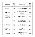
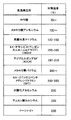
まず、図1(a)に示すように、複数の接続端子11を有する回路基板10上に、導電性粒子(例えば、Cu等)12と気泡発生剤(例えば、イソプロピルアルコール等)を含有した樹脂(例えば、エポキシ樹脂等)13を供給する。次に、図1(b)に示すように、樹脂13表面に、複数の電極端子21を有する半導体チップ20を、回路基板10に対向させて配設する。このとき、半導体チップ20の電極端子21は、回路基板10の接続端子11に位置合わせされている。
First, as shown in FIG. 1A, a resin containing conductive particles (for example, Cu) 12 and a bubble generating agent (for example, isopropyl alcohol) on a
なお、ここに示した工程は、先に、回路基板10と半導体チップ20を一定の隙間(例えば、10〜80μm)を設けて互いに対向させて配置し、然る後、導電性粒子12と気泡発生剤を含有した樹脂13を、この隙間に供給してもよい。
In the process shown here, first, the
この状態で、樹脂13を所定の温度(例えば、100〜150℃)に加熱すると、図1(c)に示すように、樹脂13中に含有する気泡発生剤から気泡30が発生する。発生した気泡30は、図1(d)に示すように、徐々に成長し、成長した気泡30によって、樹脂13は、この気泡30外に押し出される。
When the
押し出された樹脂13は、図2(a)に示すように、回路基板10の接続端子11と半導体チップ20の電極端子21間に柱状(例えば、略円柱状)に自己集合する。このとき、端子間に自己集合しなかった樹脂13のほとんどは、成長した気泡30の圧力によって、回路基板10と半導体チップ20の隙間から外部に押し出される。
As shown in FIG. 2A, the extruded
次に、この状態で、図2(b)に示すように、半導体チップ20を回路基板10に矢印の方向に押圧する。ここで、押圧の大きさは、例えば、20k〜200kPa程度に設定される。この押圧により、対向する端子間に自己集合した樹脂13中に含有する導電性粒子12同士が互いに接触することによって、端子間を電気的に接続する。このとき、端子間には、少なくとも一つ以上の導電性粒子12が介在した状態で、端子間の電気的接続を図っている。なお、押圧の際、樹脂13中に含有する導電性粒子12は、樹脂13の粘性による応力が働くので、樹脂13外に流出することはない。
Next, in this state, as shown in FIG. 2B, the
この状態で、図2(c)に示すように、対向する端子間に自己集合した樹脂13を硬化させることによって、半導体チップ20を回路基板10に固定させる。樹脂13は、端子面全体に拡がっているので、半導体チップ20を回路基板10に固定するには十分であるが、必要に応じて、半導体チップ20と回路基板10の隙間にアンダーフィル材14を注入し、然る後、アンダーフィル材14を硬化させて、半導体チップ20の回路基板10への固定をさらに強化してもよい。なお、アンダーフィル材14の供給は、半導体チップ20を回路基板10に押圧する前に行なってもよい。
In this state, as shown in FIG. 2C, the
本発明によれば、回路基板10と半導体チップ20の隙間に供給された導電性粒子12と気泡発生剤を含有した樹脂13を加熱することによって、気泡発生剤から気泡を発生させ、当該気泡が成長することで樹脂13を気泡外に押し出すことにより、樹脂13を回路基板10の接続端子11と半導体チップ20の電極端子21との間に自己集合させることができる。そして、半導体チップ20を回路基板10に押圧することによって、対向する端子間に自己集合した樹脂13中に含有する導電性粒子12同士を互いに接触させて、端子間を電気的に接続することができる。これにより、樹脂13中に分散した導電性粒子12を効率よく端子間に自己集合させ、端子間の導電に寄与させることができるので、安定した導通状態が得られ、信頼性の高い電気的接続が達成できる。
According to the present invention, by heating the
ここで、図1(a)〜(d)、及び図2(a)〜(c)に示した各構成の大きさや相対的な位置関係(例えば、導電性粒子12の大きさや、回路基板10と半導体チップ20との隙間の間隔等)は、説明を容易にするために便宜的に現されたもので、実際の大きさ等を示したものではない。
Here, the size and relative positional relationship of each component shown in FIGS. 1A to 1D and FIGS. 2A to 2C (for example, the size of the
図3(a)及び(b)は、上記のフリップチップ実装方法において、樹脂13の加熱工程における温度プロファイル、及び押圧工程における圧力プロファイルの一例をそれぞれ示したグラフである。
FIGS. 3A and 3B are graphs respectively showing an example of a temperature profile in the heating process of the
図3(a)に示すように、まず、樹脂13を、樹脂13中に含有する気泡発生剤から気泡30が発生する温度T1に加熱する。この温度T1を一定時間t1保持し、この間、発生した気泡30が成長することによって、樹脂13が気泡30外に押し出され、対向する端子間に柱状に自己集合する。ここで、温度T1は、例えば、100〜180℃、一定時間t1は、例えば、5〜10秒程度に設定される。
As shown in FIG. 3A, first, the
次に、この状態で、図3(b)に示すように、半導体チップ20を回路基板10に矢印の方向に圧力P1で、一定時間t2押圧する。この押圧により、対向する端子間に自己集合した樹脂13中に含有する導電性粒子12同士が互いに接触することによって、端子間を電気的に接続する。なお、このときの樹脂13は、一定の加熱温度T1に維持される。ここで、圧力P1は、例えば、70〜200kPa、一定時間t2は、例えば、0〜5秒程度に設定される。
Next, in this state, as shown in FIG. 3 (b), at a pressure P 1 in the direction of arrow a
そして、最後に、図3(a)に示すように、樹脂13を、樹脂13が硬化する温度T3に加熱する。この温度T3を一定時間t3保持し、対向する端子間に残存する樹脂13を硬化させることによって、半導体チップ20を回路基板10に固定させる。ここで、温度T3は、例えば、150〜250℃、一定時間t3は、例えば、10〜20秒程度に設定される。
And, finally, as shown in FIG. 3 (a), to heat the
なお、図3(a)に示した温度プロファイルは、気泡発生剤から気泡30を発生させる加熱温度を、時間t1(またはt1+t2の時間)の間、一定温度T1に保つようにしているが、この間、徐々に温度を上昇させていってもよい。
In the temperature profile shown in FIG. 3A, the heating temperature for generating the
ここで、本発明のフリップチップ実装方法において、そのポイントとなる樹脂13の端子間への自己集合について、図4(a)、(b)を参照しながら、そのメカニズムを簡単に説明する。
Here, in the flip chip mounting method of the present invention, the mechanism of the self-assembly between the terminals of the
図4(a)は、樹脂13が、成長した気泡(不図示)によって、回路基板10の接続端子11と半導体チップ20の電極端子21との間に押し出された状態を示した図である。接続端子11及び電極端子21に接した樹脂13は、その界面における界面張力(いわゆる樹脂の濡れ広がりに起因する力)Fsが、樹脂の粘度ηから発生する応力Fηよりも大きいので、接続端子11及び電極端子21の全面に亙って広がり、最終的に、端子11、12の端部を境とした柱状樹脂が形成される。そのため、接続端子11と電極端子21の対向する位置が多少ずれていても、確実に樹脂13を端子間に界面張力で自己集合させることができる。
FIG. 4A is a view showing a state in which the
なお、端子間に自己成長して形成された柱状の樹脂13には、図4(b)に示すように、気泡30の成長(または移動)による応力Fbが加わるが、樹脂13の粘度ηによる逆向きの応力Fηの作用により、その形状を維持することができ、一旦自己集合した樹脂13が消滅することはない。また、樹脂13と気体(例えば気泡30)との境界には、表面張力(又は、気−液の界面張力)が働いており、この表面張力も柱状の樹脂13の形状維持に作用し得る。
Note that the
上述のように、本発明のフリップチップ実装方法においては、気泡発生剤から発生する気泡の成長が、樹脂を端子間に自己集合させる作用を担うものであるが、さらに、その作用効果を高めるために、樹脂の加熱工程中において、回路基板10と半導体チップ20との隙間の間隔(ギャップ)を変動させることが有効である。
As described above, in the flip chip mounting method of the present invention, the growth of bubbles generated from the bubble generating agent is responsible for the self-assembly of the resin between the terminals. In addition, it is effective to vary the gap (gap) between the
図5(a)〜(c)は、樹脂13の加熱工程の中で、樹脂13中に含有する気泡発生剤から気泡を発生させ、当該気泡が成長することで樹脂13を端子間に自己集合させる工程において、回路基板10と半導体チップ20とのギャップを変動させる例を示した図である。
5 (a) to 5 (c) show that during the heating process of the
図5(a)は、回路基板10と半導体チップ20との隙間に、導電性粒子12と気泡発生剤(不図示)を含有する樹脂13を供給した状態を示したものであるが、このときの回路基板10と半導体チップ20のギャップL1は狭くなっている。
FIG. 5A shows a state where the
この状態から、図5(b)に示すように、回路基板10と半導体チップ20のギャップL2を広げながら、樹脂13を加熱する。この加熱工程において、気泡発生剤から発生した気泡30は、徐々に成長していくが、その過程で、回路基板10と半導体チップ20のギャップL2も広がっていくので、当初、回路基板10と半導体チップ20との隙間に供給された一定の量の樹脂13を、効率よく接続端子11と電極端子21間に自己集合させることができる。
From this state, as shown in FIG. 5 (b), with an increasing gap L 2 of the
図5(c)は、回路基板10と半導体チップ20のギャップがL3の時点で、対向する端子間に自己集合した樹脂13の状態を示したもので、隣接する端子間には、樹脂13はほとんど残存しない。これは、端子間に自己集合しなかった樹脂13のほとんどが、成長した気泡30の圧力によって、回路基板10と半導体チップ20の隙間から外部に押し出されたことによる。
FIG. 5 (c), the gap of the
なお、図5(a)〜(c)では、加熱工程において、回路基板10と半導体チップ20のギャップを広げる例を説明したが、ギャップを周期的に変動させながら行なっても、同様の作用効果を得ることができる。
In FIGS. 5A to 5C, the example in which the gap between the
本発明のフリップチップ実装方法の特徴の一つは、樹脂13中に含有する気泡発生剤から気泡を発生させ、当該気泡が成長することによって、樹脂13を対向する端子間に自己集合させる点にある。図1(a)〜(c)、及び図2(a)〜(c)に示した例では、気泡発生剤として、1種類のものを示したが、例えば、沸点の異なる2種類以上の材料からなるものであってもよい。
One of the features of the flip-chip mounting method of the present invention is that bubbles are generated from the bubble generating agent contained in the
図6は、沸点の異なる2種類の気泡発生剤が樹脂13中に含有された例を示した図で、樹脂13を加熱し、気泡発生剤から気泡が発生した状態を示している。沸点の低い方の気泡発生剤から発生した気泡30aは、沸点の高い方の気泡発生剤から発生した気泡30bに比べて、気泡の成長が時間的に進んでいる分、大きくなっている。
FIG. 6 is a diagram showing an example in which two types of bubble generating agents having different boiling points are contained in the
成長した気泡30bは、その成長する圧力によって、樹脂13を気泡外に押し出し、その一部を、回路基板10の接続端子11と半導体チップ20の電極端子21との間に運ぶことができるが、後に取り残された樹脂13もある。そこで、この取り残された樹脂13を、遅れて成長する気泡30bによって、再び、気泡外に押し出す動作を繰り返すことによって、効率よく樹脂13を端子間に運ぶようにすることができる。これにより、樹脂13を端子間に均一性よく自己集合させることができる。
The
ここで、本発明のフリップチップ実装方法に使用する樹脂13、導電性粒子12、及び気泡発生剤は、特に限定されないが、それぞれ、以下のような材料を使用することができる。
Here, the
樹脂13としては、エポキシ樹脂、フェノール樹脂、シリコーン樹脂等の熱硬化性樹脂、あるいは、熱可塑性樹脂等を使用することができるが、少なくとも、樹脂13の加熱工程において、流動可能な程度の粘度を有していることが好ましい。
As the
また、導電性粒子12としては、Cu、Ag、AgCu等を使用することができる。なお、本発明においては、導電性粒子同士の接触によって端子間の電気的接続を図ることから、導電性粒子の表面には、できるだけ酸化膜が成長しないようにしておくことが好ましい。また、互いに接触する導電性粒子同士の表面だけ溶融して、互いの界面で金属結合をなすような状態であってもよい。なお、導電性粒子12の樹脂13中の含有率は、例えば、0.5〜30体積%程度が好ましい。また、気泡発生剤の樹脂13中の含有率は、例えば、0.1〜20重量%程度が好ましい。
As the
気泡発生剤としては、図7に示した材料を使用することができる。なお、気泡発生剤から気泡(H2O、CO2、N2等の気体)を発生させる加熱工程において、導電性粒子12が溶融しないように、気泡発生時の沸点が、導電性粒子12の融点よりも低い材料を選択する必要がある。
As the bubble generating agent, the material shown in FIG. 7 can be used. In addition, in the heating step for generating bubbles (gases such as H 2 O, CO 2 , and N 2 ) from the bubble generating agent, the boiling point at the time of bubble generation is such that the
なお、気泡発生剤として、樹脂が加熱されたときに、気泡発生剤が熱分解することにより気泡を発生する材料も使用することができる。そのような気泡発生剤としては、図8に挙げた材料を使用することができる。例えば、結晶水を含む化合物(水酸化アルミニウム)を使用した場合、樹脂が加熱されたときに熱分解し、水蒸気が気泡となって発生する。 As the bubble generating agent, a material that generates bubbles by thermally decomposing the bubble generating agent when the resin is heated can also be used. As such a bubble generating agent, the materials shown in FIG. 8 can be used. For example, when a compound containing crystallization water (aluminum hydroxide) is used, it thermally decomposes when the resin is heated, and water vapor is generated as bubbles.
以上説明したフリップチップ実装方法において、半導体チップ20は、半導体ベアチップが複数の電極端子(ランド)を有するインターポーザに搭載された構成(例えば、CSP、BGA等)であってもよい。また、本発明は、フリップチップ実装だけでなく、それぞれ複数の電極を有する基板同士の電極間を電気的に接続する基板間接続にも適用することができる。基板間接続は、以下の方法で行うことができる。
In the flip chip mounting method described above, the
まず、複数の電極を有する第1の基板と第2の基板との隙間に、導電性粒子と気泡発生剤を含有した樹脂を供給し、然る後、当該樹脂を加熱して、樹脂中に含有する気泡発生剤から気泡を発生させる。この加熱工程で、樹脂は、気泡発生剤から発生した気泡が成長することで、当該気泡外に押し出されることによって、第1の基板の電極と第2の基板の電極間に自己集合する。 First, a resin containing conductive particles and a bubble generating agent is supplied to a gap between a first substrate having a plurality of electrodes and a second substrate, and then the resin is heated to enter the resin. Bubbles are generated from the contained bubble generating agent. In this heating process, the resin self-assembles between the electrodes on the first substrate and the second substrate by being pushed out of the bubbles as bubbles generated from the bubble generating agent grow.
次に、第2の基板を、第1の基板に押圧して、対向する電極間に自己集合した樹脂中に含有する導電性粒子同士を互いに接触させる。これにより、対向する電極間を電気的に接続させることができる。 Next, the second substrate is pressed against the first substrate to bring the conductive particles contained in the resin self-assembled between the opposing electrodes into contact with each other. Thereby, the electrodes which oppose can be electrically connected.
最後に、電極間に自己集合した樹脂を硬化することによって、第1の基板と第2の基板を固定し、基板間接続を完成させる。 Finally, the self-assembled resin between the electrodes is cured to fix the first substrate and the second substrate, thereby completing the connection between the substrates.
ここで、第1の基板又は第2の基板としては、回路基板、半導体ウエハ、半導体チップ(ベアチップ、実装チップを含む)等を使用することができる。 Here, as the first substrate or the second substrate, a circuit board, a semiconductor wafer, a semiconductor chip (including a bare chip and a mounting chip), or the like can be used.
なお、この基板間接続方法においても、上記のフリップチップ実装方法で説明した種々の条件又は方法を適用することができる。例えば、樹脂13の加熱工程における温度プロファイルは、図3(a)に示したプロファイルを、また、基板間のギャップの変動については、図5に示した方法を、それぞれ適用することができる。
In this inter-substrate connection method, the various conditions or methods described in the above flip chip mounting method can be applied. For example, the profile shown in FIG. 3A can be applied to the temperature profile in the heating process of the
また、使用する樹脂13、導電性粒子12、気泡発生剤についても、フリップチップ実装方法で説明した材料を適宜選んで使用することができる。
In addition, the
以上、本発明に係るフリップチップ実装方法、及び基板間接続方法について説明してきたが、例えば、フリップチップ実装方法を実行して、フリップチップ実装体を製造する装置は、図9に示すようなフリップチップ実装装置40で実現することができる。
Although the flip chip mounting method and the inter-substrate connection method according to the present invention have been described above, for example, an apparatus for manufacturing a flip chip mounting body by executing the flip chip mounting method is a flip as shown in FIG. It can be realized by the
図9のブロック図に示すように、フリップチップ実装装置40は、半導体チップ20と回路基板10を、一定の隙間をもって互いに対向させて保持する保持手段41、半導体チップ20と回路基板10との隙間に、導電性粒子12と気泡発生剤を含有した樹脂13を供給する供給手段42、樹脂13を加熱する加熱手段43、及び半導体チップ20を回路基板10に押圧する押圧手段46とで構成されている。また、加熱手段43は、樹脂13中に含有する気泡発生剤から気泡を発生させる温度に加熱制御する第1の加熱手段44と、樹脂13を熱硬化する温度に加熱制御する第2の加熱手段45を有している。
As shown in the block diagram of FIG. 9, the flip
ここで、保持手段41には、半導体チップ20の電極端子と、回路基板10の接続端子との位置を合わせるアライメント機構が付いている。また、供給手段42は、樹脂がペースト状であれば、ディスペンサ等を用いることができ、加熱手段43は、加熱ステージ(ホットプレート)や、熱風や赤外線によって加熱される加熱ボックス(オーブン)等が使用できる。
Here, the holding means 41 is provided with an alignment mechanism that aligns the positions of the electrode terminals of the
このフリップチップ実装装置40において、第1の加熱手段44で加熱された樹脂13は、気泡発生剤から発生した気泡が成長することで、当該気泡外に押し出されることによって、回路基板10の接続端子11と半導体チップ20の電極端子21との間に自己集合する。そして、押圧手段46により、半導体チップ20を回路基板10に押圧することによって、対向する電極間に自己集合した樹脂13中に含有する導電性粒子12同士を互いに接触させ、フリップチップ実装体を完成させる。
In the flip-
ところで、はんだ粉(導電性粒子)を含有させた樹脂を用いて、半導体チップと回路基板との対向する端子間の電気的接続と、半導体チップの回路基板への固定を同時に行なう方法が、特許文献5(特開2002−26070号公報)、及び特許文献6(特開平11−186334号公報)に記載されている。ここに記載された方法は、樹脂中に含有させたはんだ粉を溶融することによって、半導体チップ及び回路基板の対向する端子が当接する部位を半田付けするとともに、その後、樹脂を硬化することによって、半導体チップを回路基板に封止、固定するもので、一見、本発明と類似した技術のようにも見える。しかしながら、ここに記載された方法は、いわゆるリフロー処理によって端子間をはんだ付けするもので、従って、樹脂封止後においても、樹脂中にはんだ粉は分散されており、本発明のように、導電性粒子を含有する樹脂を対向する端子間に自己集合させた後、樹脂中に含有する導電性粒子同士を互いに接触させて端子間の電気的接続を図るものではなく、本発明とは本質的に異なる技術である。 By the way, there is a method in which a resin containing solder powder (conductive particles) is used to simultaneously perform electrical connection between opposing terminals of a semiconductor chip and a circuit board and fixing the semiconductor chip to the circuit board. It is described in Document 5 (Japanese Patent Laid-Open No. 2002-26070) and Patent Document 6 (Japanese Patent Laid-Open No. 11-186334). The method described here melts the solder powder contained in the resin, solders the part where the opposing terminals of the semiconductor chip and the circuit board contact, and then hardens the resin, The semiconductor chip is sealed and fixed to a circuit board. At first glance, it looks like a technique similar to the present invention. However, the method described here is to solder between terminals by so-called reflow treatment. Therefore, even after resin sealing, the solder powder is dispersed in the resin. After the self-assembly of the resin containing the conductive particles between the terminals facing each other, the conductive particles contained in the resin are brought into contact with each other to achieve electrical connection between the terminals. Is a different technology.
また、導電性粒子(低融点金属フィラー)を含有させた樹脂を用いて、半導体チップと回路基板の対向する端子間の電気的接続と、半導体チップの回路基板への固定を同時に行なう方法が、特許文献7(特開2004−260131号公報)、及び非特許文献1(安田真大他,「低融点金属フィラー含有樹脂による自己組織化接合プロセス」,第10回「エレクトロニクスにおけるマイクロ接合・実装技術」シンポジウム(10th Symposium on "Microjoing and Assembly Technology in Electronics"),183−188頁,2004年)に記載されている。ここには、酸化還元能力を有する樹脂を用いて、樹脂中に含有する溶融した金属フィラーの凝集や濡れに基づいて、選択的に端子間に導電性粒子が自己組織化した接続体を形成する技術が開示されている。 Further, using a resin containing conductive particles (low melting point metal filler), a method of simultaneously performing electrical connection between terminals facing the semiconductor chip and the circuit board and fixing the semiconductor chip to the circuit board, Patent Document 7 (Japanese Patent Laid-Open No. 2004-260131) and Non-Patent Document 1 (Masada Yasuda et al., “Self-Organized Joining Process Using Resin with Low Melting Point Metal Filler”, 10th “Microjoining / Mounting Technology in Electronics” "10th Symposium on" Microjoing and Assembly Technology in Electronics "", pp. 183-188, 2004). Here, using a resin having oxidation-reduction ability, a connection body in which conductive particles are selectively self-organized between terminals is selectively formed based on the aggregation and wetting of the molten metal filler contained in the resin. Technology is disclosed.
しかしながら、特許文献7及び非特許文献1は、対向する端子間を選択的(自己集合的)に接合を行うプロセスの可能性を示唆するに止まり、もっぱら、溶融した導電性粒子の濡れ性のみによって端子間に凝集(自己集合)させているので、端子間に形成される接続体を均一に形成することは難しい。 However, Patent Document 7 and Non-Patent Document 1 only suggest the possibility of a process of selectively (self-assembling) bonding between opposing terminals, and only by the wettability of the molten conductive particles. Since the terminals are aggregated (self-assembled) between the terminals, it is difficult to uniformly form the connection body formed between the terminals.
本発明は、導電性粒子を含有する樹脂が、溶融した導電性粒子が自由に移動できるほどの”海”の役目を果たすものではないために、導電性粒子の結合過程が均一に進行せず、その結果、端子間に均一な接合体を形成することができないという認識のもとになされたもので、本発明による方法を適用することによって、多数の電極端子を有する半導体チップを歩留まりよくフリップチップ実装することができ、量産工程に適用可能な有用な方法を提供するものである。 In the present invention, since the resin containing conductive particles does not serve as a “sea” that allows the molten conductive particles to move freely, the bonding process of the conductive particles does not proceed uniformly. As a result, it was made based on the recognition that a uniform joined body cannot be formed between the terminals. By applying the method according to the present invention, a semiconductor chip having a large number of electrode terminals can be flipped with a high yield. The present invention provides a useful method that can be mounted on a chip and is applicable to a mass production process.
以上、本発明を好適な実施形態により説明してきたが、こうした記述は限定事項ではなく、勿論、種々の改変が可能である。 As mentioned above, although this invention was demonstrated by suitable embodiment, such description is not a limitation matter and of course various modifications are possible.
本発明によれば、次世代LSIのフリップチップ実装に適用可能な、生産性及び信頼性の高いフリップチップ実装方法、及び基板間接続方法を提供することができる。 According to the present invention, it is possible to provide a flip-chip mounting method and a substrate-to-substrate connection method that are applicable to flip-chip mounting of next-generation LSIs and have high productivity and reliability.
10 回路基板
11 接続端子
12 導電性粒子
13 樹脂
14 アンダーフィル材
20 半導体チップ
21 電極端子
30,30a,30b 気泡
40 フリップチップ実装装置
41 保持手段
42 供給手段
43 加熱手段
44 第1の加熱手段
45 第2の加熱手段
46 押圧手段
DESCRIPTION OF
Claims (17)
前記回路基板と前記半導体チップとの隙間に、導電性粒子と気泡発生剤を含有した樹脂を供給する第1の工程と、
前記樹脂を加熱して、前記樹脂中に含有する前記気泡発生剤から気泡を発生させる第2の工程と、
前記半導体チップを、前記回路基板に押圧する第3の工程と、
前記樹脂を硬化する第4の工程と
を含み、
前記第2の工程において、前記樹脂は、前記気泡発生剤から発生した気泡が成長することで該気泡外に押し出されることによって、前記回路基板の接続端子と前記半導体チップの電極端子間に自己集合し、
前記第3の工程において、前記端子間に自己集合した前記樹脂中に含有する導電性粒子同士が互いに接触することによって、前記端子間を電気的に接続し、
前記第4の工程において、前記端子間の前記樹脂を硬化することによって、前記半導体チップを前記回路基板に固定することを特徴とするフリップチップ実装方法。In a flip chip mounting method in which a semiconductor chip having a plurality of electrode terminals is arranged to face a circuit board having a plurality of connection terminals, and the connection terminals of the circuit board and the electrode terminals of the semiconductor chip are electrically connected. ,
A first step of supplying a resin containing conductive particles and a bubble generating agent into a gap between the circuit board and the semiconductor chip;
A second step of heating the resin to generate bubbles from the bubble generating agent contained in the resin;
A third step of pressing the semiconductor chip against the circuit board;
A fourth step of curing the resin,
In the second step, the resin is self-assembled between the connection terminal of the circuit board and the electrode terminal of the semiconductor chip by being pushed out of the bubble by the growth of bubbles generated from the bubble generating agent. And
In the third step, the conductive particles contained in the resin self-assembled between the terminals contact each other, thereby electrically connecting the terminals,
In the fourth step, the semiconductor chip is fixed to the circuit board by curing the resin between the terminals.
前記第1の基板と前記第2の基板との隙間に、導電性粒子と気泡発生剤を含有した樹脂を供給する第1の工程と、
前記樹脂を加熱して、前記樹脂中に含有する前記気泡発生剤から気泡を発生させる第2の工程と、
前記第2の基板を、前記第1の基板に押圧する第3の工程と、
前記樹脂を硬化する第4の工程と
を含み、
前記第2の工程において、前記樹脂は、前記気泡発生剤から発生した気泡が成長することで該気泡外に押し出されることによって、前記第1の基板の電極と前記第2の基板の電極間に自己集合し、
前記第3の工程において、前記電極間に自己集合した前記樹脂中に含有する導電性粒子同士が互いに接触することによって、前記電極間を電気的に接続し、
前記第4の工程において、前記電極間に自己集合した前記樹脂を硬化することによって、前記第1の基板を前記第2の基板に固定することを特徴とする基板間接続方法。A substrate in which a second substrate having a plurality of electrodes is arranged opposite to a first substrate having a plurality of electrodes, and the electrodes of the first substrate and the electrodes of the second substrate are electrically connected In the connection method between
A first step of supplying a resin containing conductive particles and a bubble generating agent into a gap between the first substrate and the second substrate;
A second step of heating the resin to generate bubbles from the bubble generating agent contained in the resin;
A third step of pressing the second substrate against the first substrate;
A fourth step of curing the resin,
In the second step, the resin is pushed out of the bubbles by the growth of bubbles generated from the bubble generating agent, thereby causing the resin between the electrodes of the first substrate and the second substrate. Self-assemble,
In the third step, the conductive particles contained in the resin self-assembled between the electrodes contact each other to electrically connect the electrodes,
In the fourth step, the first substrate is fixed to the second substrate by curing the resin self-assembled between the electrodes.
前記接続端子と前記電極端子は、前記回路基板と前記半導体チップとの隙間に供給された導電性粒子と気泡発生剤を含有する樹脂が、前記接続端子と前記電極端子間に自己集合し、該自己集合した前記樹脂中の導電性粒子同士が接触することによって、電気的に接続されていることを特徴とするフリップチップ実装体。A flip chip mounting body in which a semiconductor chip having a plurality of electrode terminals is arranged opposite to a circuit board having a plurality of connection terminals, and the connection terminals of the circuit board and the electrode terminals of the semiconductor chip are electrically connected In
In the connection terminal and the electrode terminal, the resin containing the conductive particles and the bubble generating agent supplied to the gap between the circuit board and the semiconductor chip is self-assembled between the connection terminal and the electrode terminal, A flip chip mounting body characterized in that the self-assembled conductive particles in the resin are electrically connected to each other by contact.
Applications Claiming Priority (3)
| Application Number | Priority Date | Filing Date | Title |
|---|---|---|---|
| JP2005094233 | 2005-03-29 | ||
| JP2005094233 | 2005-03-29 | ||
| PCT/JP2006/305274 WO2006103949A1 (en) | 2005-03-29 | 2006-03-16 | Flip chip mounting method and method for connecting substrates |
Related Child Applications (1)
| Application Number | Title | Priority Date | Filing Date |
|---|---|---|---|
| JP2007317969A Division JP2008078682A (en) | 2005-03-29 | 2007-12-10 | Flip-chip mounting device |
Publications (2)
| Publication Number | Publication Date |
|---|---|
| JP4084835B2 true JP4084835B2 (en) | 2008-04-30 |
| JPWO2006103949A1 JPWO2006103949A1 (en) | 2008-09-04 |
Family
ID=37053210
Family Applications (2)
| Application Number | Title | Priority Date | Filing Date |
|---|---|---|---|
| JP2007510387A Expired - Fee Related JP4084835B2 (en) | 2005-03-29 | 2006-03-16 | Flip chip mounting method and inter-board connection method |
| JP2007317969A Pending JP2008078682A (en) | 2005-03-29 | 2007-12-10 | Flip-chip mounting device |
Family Applications After (1)
| Application Number | Title | Priority Date | Filing Date |
|---|---|---|---|
| JP2007317969A Pending JP2008078682A (en) | 2005-03-29 | 2007-12-10 | Flip-chip mounting device |
Country Status (6)
| Country | Link |
|---|---|
| US (2) | US7531385B1 (en) |
| EP (1) | EP1865550A4 (en) |
| JP (2) | JP4084835B2 (en) |
| KR (1) | KR101181140B1 (en) |
| CN (1) | CN100495676C (en) |
| WO (1) | WO2006103949A1 (en) |
Cited By (1)
| Publication number | Priority date | Publication date | Assignee | Title |
|---|---|---|---|---|
| KR20160014671A (en) | 2013-05-30 | 2016-02-11 | 가부시키가이샤 리코 | Toner container, process cartridge, and image forming apparatus |
Families Citing this family (32)
| Publication number | Priority date | Publication date | Assignee | Title |
|---|---|---|---|---|
| US8212004B2 (en) * | 1999-03-02 | 2012-07-03 | Human Genome Sciences, Inc. | Neutrokine-alpha fusion proteins |
| JP3955302B2 (en) * | 2004-09-15 | 2007-08-08 | 松下電器産業株式会社 | Method of manufacturing flip chip mounting body |
| EP1865549A4 (en) * | 2005-03-29 | 2012-07-11 | Panasonic Corp | Flip chip mounting method and bump forming method |
| WO2006123554A1 (en) * | 2005-05-17 | 2006-11-23 | Matsushita Electric Industrial Co., Ltd. | Flip-chip mounting body and flip-chip mounting method |
| US7640659B2 (en) * | 2005-09-02 | 2010-01-05 | Panasonic Corporation | Method for forming conductive pattern and wiring board |
| WO2007122868A1 (en) * | 2006-03-28 | 2007-11-01 | Matsushita Electric Industrial Co., Ltd. | Method for forming bump and device for forming bump |
| JP5004654B2 (en) | 2007-05-16 | 2012-08-22 | パナソニック株式会社 | Wiring board connection method and wiring board structure |
| KR100886712B1 (en) * | 2007-07-27 | 2009-03-04 | 주식회사 하이닉스반도체 | Semiconductor package and method of manufacturing the same |
| US7812336B2 (en) * | 2007-12-07 | 2010-10-12 | METAMEMS Corp. | Levitating substrate being charged by a non-volatile device and powered by a charged capacitor or bonding wire |
| US20090149038A1 (en) * | 2007-12-07 | 2009-06-11 | Metamems Llc | Forming edge metallic contacts and using coulomb forces to improve ohmic contact |
| US8008070B2 (en) * | 2007-12-07 | 2011-08-30 | METAMEMS Corp. | Using coulomb forces to study charateristics of fluids and biological samples |
| US8159809B2 (en) * | 2007-12-07 | 2012-04-17 | METAMEMS Corp. | Reconfigurable system that exchanges substrates using coulomb forces to optimize a parameter |
| US8531848B2 (en) * | 2007-12-07 | 2013-09-10 | METAMEMS Corp. | Coulomb island and Faraday shield used to create adjustable Coulomb forces |
| US7863651B2 (en) * | 2007-12-07 | 2011-01-04 | METAMEMS Corp. | Using multiple coulomb islands to reduce voltage stress |
| US7728427B2 (en) * | 2007-12-07 | 2010-06-01 | Lctank Llc | Assembling stacked substrates that can form cylindrical inductors and adjustable transformers |
| US8018009B2 (en) * | 2007-12-07 | 2011-09-13 | METAMEMS Corp. | Forming large planar structures from substrates using edge Coulomb forces |
| US7965489B2 (en) * | 2007-12-07 | 2011-06-21 | METAMEMS Corp. | Using coulomb forces to form 3-D reconfigurable antenna structures |
| US7946174B2 (en) * | 2007-12-07 | 2011-05-24 | METAMEMS Corp. | Decelerometer formed by levitating a substrate into equilibrium |
| JP2009186707A (en) * | 2008-02-06 | 2009-08-20 | Seiko Epson Corp | Method of manufacturing electro-optical device and electro-optical device |
| JP5247571B2 (en) * | 2008-04-24 | 2013-07-24 | パナソニック株式会社 | Wiring board and wiring board connection method |
| JP2010034504A (en) * | 2008-07-02 | 2010-02-12 | Panasonic Corp | Method for mutually connecting substrates, flip chip mounting body, and mutual connection structure between substrates |
| JP4816750B2 (en) * | 2009-03-13 | 2011-11-16 | 住友電気工業株式会社 | Connection method of printed wiring board |
| CN101661916B (en) * | 2009-09-18 | 2012-05-09 | 可富科技股份有限公司 | Structure for re-wiring layer on soft film flip chip encapsulation |
| JP5540916B2 (en) * | 2010-06-15 | 2014-07-02 | デクセリアルズ株式会社 | Method for manufacturing connection structure |
| US8951445B2 (en) * | 2011-04-14 | 2015-02-10 | International Business Machines Corporation | Bridging arrangement and method for manufacturing a bridging arrangement |
| JP2011233921A (en) * | 2011-07-15 | 2011-11-17 | Sumitomo Electric Ind Ltd | Connection structure of printed wiring boards |
| US9726691B2 (en) * | 2014-01-07 | 2017-08-08 | International Business Machines Corporation | 3D chip testing through micro-C4 interface |
| US9230832B2 (en) * | 2014-03-03 | 2016-01-05 | International Business Machines Corporation | Method for manufacturing a filled cavity between a first and a second surface |
| JP7160302B2 (en) * | 2018-01-31 | 2022-10-25 | 三国電子有限会社 | CONNECTED STRUCTURE AND METHOD OF MAKING CONNECTED STRUCTURE |
| JP7046351B2 (en) | 2018-01-31 | 2022-04-04 | 三国電子有限会社 | How to make a connection structure |
| JP7185252B2 (en) | 2018-01-31 | 2022-12-07 | 三国電子有限会社 | Method for producing connection structure |
| CN111048499B (en) * | 2019-12-16 | 2022-05-13 | 业成科技(成都)有限公司 | Micro light-emitting diode display panel and preparation method thereof |
Family Cites Families (24)
| Publication number | Priority date | Publication date | Assignee | Title |
|---|---|---|---|---|
| JPH0747233B2 (en) | 1987-09-14 | 1995-05-24 | 古河電気工業株式会社 | Solder deposition composition and solder deposition method |
| JPH06125169A (en) | 1992-10-13 | 1994-05-06 | Fujitsu Ltd | Pre-soldering method |
| US5597469A (en) * | 1995-02-13 | 1997-01-28 | International Business Machines Corporation | Process for selective application of solder to circuit packages |
| DE19640192A1 (en) * | 1996-09-30 | 1998-04-02 | Bosch Gmbh Robert | Process for flip chip assembly |
| JP3678547B2 (en) * | 1997-07-24 | 2005-08-03 | ソニーケミカル株式会社 | Multilayer anisotropic conductive adhesive and method for producing the same |
| US5904156A (en) * | 1997-09-24 | 1999-05-18 | International Business Machines Corporation | Dry film resist removal in the presence of electroplated C4's |
| JPH11186334A (en) | 1997-12-25 | 1999-07-09 | Toshiba Corp | Semiconductor mounting apparatus, manufacture thereof and anisotropically conductive material |
| EP1050888B1 (en) * | 1998-08-28 | 2010-10-06 | Panasonic Corporation | Conductive paste, conductive structure using the same, electronic part, module, circuit board, method for electrical connection, method for manufacturing circuit board, and method for manufacturing ceramic electronic part |
| JP3996276B2 (en) | 1998-09-22 | 2007-10-24 | ハリマ化成株式会社 | Solder paste, manufacturing method thereof, and solder pre-coating method |
| JP4142800B2 (en) * | 1999-04-07 | 2008-09-03 | 株式会社ルネサステクノロジ | Bump forming apparatus and bump forming method |
| JP2000332055A (en) | 1999-05-17 | 2000-11-30 | Sony Corp | Flip-chip mounting structure and mounting method |
| US6570099B1 (en) * | 1999-11-09 | 2003-05-27 | Matsushita Electric Industrial Co., Ltd. | Thermal conductive substrate and the method for manufacturing the same |
| JP2002026070A (en) | 2000-07-04 | 2002-01-25 | Toshiba Corp | Semiconductor device and its manufacturing method |
| JP4659262B2 (en) * | 2001-05-01 | 2011-03-30 | 富士通セミコンダクター株式会社 | Electronic component mounting method and paste material |
| JP3769688B2 (en) | 2003-02-05 | 2006-04-26 | 独立行政法人科学技術振興機構 | Terminal connection method and semiconductor device mounting method |
| WO2004070827A1 (en) * | 2003-02-05 | 2004-08-19 | Senju Metal Industry Co., Ltd. | Method for interconnecting terminals and method for mounting semiconductor device |
| JP3964911B2 (en) * | 2004-09-03 | 2007-08-22 | 松下電器産業株式会社 | Manufacturing method of substrate with bumps |
| JP3955302B2 (en) * | 2004-09-15 | 2007-08-08 | 松下電器産業株式会社 | Method of manufacturing flip chip mounting body |
| JP4287475B2 (en) * | 2004-12-17 | 2009-07-01 | パナソニック株式会社 | Resin composition |
| JP4401411B2 (en) * | 2005-03-17 | 2010-01-20 | パナソニック株式会社 | Mounting body provided with semiconductor chip and manufacturing method thereof |
| EP1865549A4 (en) * | 2005-03-29 | 2012-07-11 | Panasonic Corp | Flip chip mounting method and bump forming method |
| CN101176200B (en) * | 2005-05-17 | 2010-11-03 | 松下电器产业株式会社 | Flip chip mounting method, flip chip mounting apparatus and flip chip mounting body |
| US7745013B2 (en) * | 2005-12-30 | 2010-06-29 | Intel Corporation | Solder foams, nano-porous solders, foamed-solder bumps in chip packages, methods of assembling same, and systems containing same |
| WO2007105535A1 (en) * | 2006-03-14 | 2007-09-20 | Matsushita Electric Industrial Co., Ltd. | Electronic part mounting structure and its manufacturing method |
-
2006
- 2006-03-16 US US11/887,331 patent/US7531385B1/en not_active Expired - Fee Related
- 2006-03-16 KR KR1020077020987A patent/KR101181140B1/en active IP Right Grant
- 2006-03-16 WO PCT/JP2006/305274 patent/WO2006103949A1/en active Application Filing
- 2006-03-16 EP EP06729267A patent/EP1865550A4/en not_active Withdrawn
- 2006-03-16 CN CN200680008173.1A patent/CN100495676C/en not_active Expired - Fee Related
- 2006-03-16 JP JP2007510387A patent/JP4084835B2/en not_active Expired - Fee Related
-
2007
- 2007-12-10 JP JP2007317969A patent/JP2008078682A/en active Pending
-
2008
- 2008-04-08 US US12/078,891 patent/US7820021B2/en not_active Expired - Fee Related
Cited By (15)
| Publication number | Priority date | Publication date | Assignee | Title |
|---|---|---|---|---|
| KR20160014671A (en) | 2013-05-30 | 2016-02-11 | 가부시키가이샤 리코 | Toner container, process cartridge, and image forming apparatus |
| US9690231B2 (en) | 2013-05-30 | 2017-06-27 | Ricoh Company, Limited | Toner container, developing device, process cartridge, and image forming apparatus that include an operating member to move a shutter for a toner outlet via a linking member |
| KR20180014256A (en) | 2013-05-30 | 2018-02-07 | 가부시키가이샤 리코 | Toner container, process cartridge, and image forming apparatus |
| US10025227B2 (en) | 2013-05-30 | 2018-07-17 | Ricoh Company, Ltd. | Toner container, developing device, process cartridge, and image forming apparatus that include a toner container contacting surface to contact with a developing device engagement releasing structure |
| KR20180087471A (en) | 2013-05-30 | 2018-08-01 | 가부시키가이샤 리코 | Toner container, process cartridge, and image forming apparatus |
| US20180253032A1 (en) | 2013-05-30 | 2018-09-06 | Tomofumi Yoshida | Toner container, developing device, process cartridge, and image forming apparatus that include a toner container contacting surface to contact with a developing device engagement releasing structure |
| KR20190080983A (en) | 2013-05-30 | 2019-07-08 | 가부시키가이샤 리코 | Toner container, process cartridge, and image forming apparatus |
| US10365584B2 (en) | 2013-05-30 | 2019-07-30 | Ricoh Company, Ltd. | Toner container, developing device, process cartridge, and image forming apparatus that include a toner container contacting surface to contact with a developing device engagement releasing structure |
| KR20190120428A (en) | 2013-05-30 | 2019-10-23 | 가부시키가이샤 리코 | Toner container, process cartridge, and image forming apparatus |
| US10564572B2 (en) | 2013-05-30 | 2020-02-18 | Ricoh Company, Ltd. | Toner container with an operating structure disposed on a first side, and a shutter disposed on a second side |
| KR20200035504A (en) | 2013-05-30 | 2020-04-03 | 가부시키가이샤 리코 | Toner container, process cartridge, and image forming apparatus |
| EP3660592A1 (en) | 2013-05-30 | 2020-06-03 | Ricoh Company, Ltd. | Toner container, process cartridge, and image forming apparatus |
| US10915040B2 (en) | 2013-05-30 | 2021-02-09 | Ricoh Company, Ltd. | Toner container with an operating structure disposed on a first side, a shutter disposed on a second side, and a lock |
| KR20210027542A (en) | 2013-05-30 | 2021-03-10 | 가부시키가이샤 리코 | Toner container, process cartridge, and image forming apparatus |
| US11231664B2 (en) | 2013-05-30 | 2022-01-25 | Ricoh Company, Ltd. | Toner container having a shutter, a lever disposed on one side, and a pivoting portion on the other side which rotate together with a common shaft |
Also Published As
| Publication number | Publication date |
|---|---|
| CN100495676C (en) | 2009-06-03 |
| US7531385B1 (en) | 2009-05-12 |
| JP2008078682A (en) | 2008-04-03 |
| EP1865550A4 (en) | 2012-07-11 |
| KR20070115957A (en) | 2007-12-06 |
| CN101142664A (en) | 2008-03-12 |
| JPWO2006103949A1 (en) | 2008-09-04 |
| KR101181140B1 (en) | 2012-09-14 |
| EP1865550A1 (en) | 2007-12-12 |
| US7820021B2 (en) | 2010-10-26 |
| WO2006103949A1 (en) | 2006-10-05 |
| US20090126876A1 (en) | 2009-05-21 |
| US20090115071A1 (en) | 2009-05-07 |
Similar Documents
| Publication | Publication Date | Title |
|---|---|---|
| JP4084835B2 (en) | Flip chip mounting method and inter-board connection method | |
| JP4084834B2 (en) | Flip chip mounting method and bump forming method | |
| JP3955302B2 (en) | Method of manufacturing flip chip mounting body | |
| KR101139050B1 (en) | Process for forming bumps and solder bump | |
| JP4402717B2 (en) | Flip chip mounting method and bump forming method using conductive particles | |
| JP4477062B2 (en) | Flip chip mounting method | |
| JP4495158B2 (en) | Flip chip mounting method, bump forming method, flip chip mounting apparatus, and bump forming apparatus | |
| WO2006064831A1 (en) | Resin composition for flip-chip packaging and resin composition for forming bump | |
| JP5173214B2 (en) | Electrically conductive resin composition and method for connecting electrodes using the same, and electrical connection method for electronic component and circuit board | |
| JPWO2007099866A1 (en) | Electronic component mounting body, electronic component with solder bump, solder resin mixture, electronic component mounting method, and electronic component manufacturing method | |
| WO2006098196A1 (en) | Package equipped with semiconductor chip and method for producing same | |
| US7905011B2 (en) | Bump forming method and bump forming apparatus | |
| CN103098191B (en) | Electronic devices and components fixing body, electronic devices and components and substrate | |
| JP4710513B2 (en) | Flip chip mounting method and inter-board connection method | |
| JP4543899B2 (en) | Flip chip mounting method and flip chip mounting apparatus |
Legal Events
| Date | Code | Title | Description |
|---|---|---|---|
| TRDD | Decision of grant or rejection written | ||
| A975 | Report on accelerated examination |
Free format text: JAPANESE INTERMEDIATE CODE: A971005 Effective date: 20080116 |
|
| A01 | Written decision to grant a patent or to grant a registration (utility model) |
Free format text: JAPANESE INTERMEDIATE CODE: A01 Effective date: 20080122 |
|
| A61 | First payment of annual fees (during grant procedure) |
Free format text: JAPANESE INTERMEDIATE CODE: A61 Effective date: 20080215 |
|
| R150 | Certificate of patent or registration of utility model |
Ref document number: 4084835 Country of ref document: JP Free format text: JAPANESE INTERMEDIATE CODE: R150 Free format text: JAPANESE INTERMEDIATE CODE: R150 |
|
| FPAY | Renewal fee payment (event date is renewal date of database) |
Free format text: PAYMENT UNTIL: 20110222 Year of fee payment: 3 |
|
| FPAY | Renewal fee payment (event date is renewal date of database) |
Free format text: PAYMENT UNTIL: 20120222 Year of fee payment: 4 |
|
| FPAY | Renewal fee payment (event date is renewal date of database) |
Free format text: PAYMENT UNTIL: 20130222 Year of fee payment: 5 |
|
| FPAY | Renewal fee payment (event date is renewal date of database) |
Free format text: PAYMENT UNTIL: 20130222 Year of fee payment: 5 |
|
| FPAY | Renewal fee payment (event date is renewal date of database) |
Free format text: PAYMENT UNTIL: 20140222 Year of fee payment: 6 |
|
| LAPS | Cancellation because of no payment of annual fees |