JP4080435B2 - Obstacle detection device and detection method - Google Patents
Obstacle detection device and detection method Download PDFInfo
- Publication number
- JP4080435B2 JP4080435B2 JP2004039132A JP2004039132A JP4080435B2 JP 4080435 B2 JP4080435 B2 JP 4080435B2 JP 2004039132 A JP2004039132 A JP 2004039132A JP 2004039132 A JP2004039132 A JP 2004039132A JP 4080435 B2 JP4080435 B2 JP 4080435B2
- Authority
- JP
- Japan
- Prior art keywords
- distance
- background information
- reflection
- reflection intensity
- range
- Prior art date
- Legal status (The legal status is an assumption and is not a legal conclusion. Google has not performed a legal analysis and makes no representation as to the accuracy of the status listed.)
- Expired - Lifetime
Links
- 238000001514 detection method Methods 0.000 title claims description 106
- 238000012545 processing Methods 0.000 claims description 31
- 238000004092 self-diagnosis Methods 0.000 claims description 15
- 238000000034 method Methods 0.000 claims description 9
- 230000008569 process Effects 0.000 claims description 7
- 230000001678 irradiating effect Effects 0.000 claims description 5
- 230000002159 abnormal effect Effects 0.000 claims description 4
- 230000005856 abnormality Effects 0.000 description 16
- 230000005540 biological transmission Effects 0.000 description 8
- 238000010586 diagram Methods 0.000 description 6
- 230000004888 barrier function Effects 0.000 description 4
- 238000005259 measurement Methods 0.000 description 4
- 238000012423 maintenance Methods 0.000 description 3
- 238000013459 approach Methods 0.000 description 2
- 230000008859 change Effects 0.000 description 2
- 238000006243 chemical reaction Methods 0.000 description 2
- 238000003745 diagnosis Methods 0.000 description 2
- 238000009434 installation Methods 0.000 description 2
- 230000002265 prevention Effects 0.000 description 2
- 238000001228 spectrum Methods 0.000 description 2
- 230000003321 amplification Effects 0.000 description 1
- 238000004364 calculation method Methods 0.000 description 1
- 238000012790 confirmation Methods 0.000 description 1
- 238000010276 construction Methods 0.000 description 1
- 230000006872 improvement Effects 0.000 description 1
- 230000007246 mechanism Effects 0.000 description 1
- 238000003199 nucleic acid amplification method Methods 0.000 description 1
- 230000003287 optical effect Effects 0.000 description 1
- 238000010183 spectrum analysis Methods 0.000 description 1
Images


Description
この発明は、例えば列車が走行する軌道の踏切道における自動車や歩行者を検知する障害物検知装置及び検知方法、特に検知精度の向上に関するものである。 The present invention relates to an obstacle detection device and a detection method for detecting an automobile or a pedestrian on, for example, a railroad crossing on which a train travels, and particularly to improvement of detection accuracy.
鉄道保安装置の踏切警報装置は、軌道上を走行する列車が踏切に接近したときに踏切警報を開始し、踏切道の通行を遮断して列車の安全運転と踏切道を通行する自動車や歩行者の安全を図り、列車が踏切道を通過した後は速やかに通行遮断を解除して円滑な道路通行を確保するようにしている。 Railroad crossing warning devices for railroad safety devices start a railroad crossing warning when a train traveling on a track approaches the railroad crossing, block traffic on the railroad crossing, and drive cars and pedestrians that pass the train safely and through the railroad crossing. In order to ensure the safety of the road, after the train crosses the railroad crossing, the road block is immediately released to ensure smooth road traffic.
この踏切道における列車の安全運行が阻害されることを防止するため、例えばレーザーセンサや赤外線センサ、可視カメラによる光学センサあるいは超音波センサ又はループコイルセンサ等を使用した踏切障害物検知装置が使用されている。これらのセンサを使用した踏切障害物検知装置は、雨や雪、霧、風などの気象や照度等の影響を受けやすく、また、システム構成によっては設置工期やコストが負担となる場合ある。これに対してマイクロ波のうち波長が数mm前後の短いミリ波を使用したセンサは、気象や照度等の影響を受けにくく、線路間に配線や配管するような大掛かりな工事は必要ないので、設置工期やコストを軽減することができるとともに、踏切内の障害物を確実に検知することができる。 In order to prevent the safe operation of the train on this railroad crossing, for example, a railroad crossing obstacle detection device using a laser sensor, an infrared sensor, an optical sensor using a visible camera, an ultrasonic sensor, a loop coil sensor, or the like is used. ing. Railroad crossing obstacle detection devices using these sensors are easily affected by weather such as rain, snow, fog, and wind, and illuminance, and depending on the system configuration, installation time and cost may be borne. On the other hand, a sensor that uses a short millimeter wave with a wavelength of around several millimeters among microwaves is not easily affected by weather, illuminance, etc., and does not require large-scale construction such as wiring or piping between lines. The installation period and cost can be reduced, and obstacles in the crossing can be reliably detected.
例えば特許文献1に示された踏切障害物検知装置は、レーザ光やミリ波を用いたレーダからなり、回転駆動する距離センサからレーザ光やミリ波を踏切内に放射し、その反射信号に基づいて物体の方位情報と、その方位情報に対応する物体の距離情報を検知し、あらかじめ記憶している方位情報毎の物体の距離情報と、検知した方位情報に対応する物体の距離情報とを比較し、検知した物体が障害物であるか否を判定するようにしている。また、踏切外の異なる3箇所の隅にそれぞれ反射板を設け、反射板の反射信号に基づいて距離センサの回転方位と送受信性能のチェックと校正を行うようにしている。
For example, a crossing obstacle detection device disclosed in
このような障害物の検出は防犯用にも応用でき、例えば特許文献2に示された進入物検出方法は、ミリ波レーダで生成されたミリ波を検知エリアに照射し、照射エリア内に設置された複数の反射物からの反射波を検出し、複数の反射物のうち少なくとも1つの反射物からの反射波を検出できない場合、検知エリアに侵入物体が存在すると判定している。また、反射波を検出できない反射物の位置応じて侵入物体の位置を特定するようにしている。
踏切内の障害物を確実に検知するためには、検知対象領域である踏切内の未検知となる死角を無くすことと、誤検知することなく確実に障害物の判定ができること及び装置の異常を判断できる自己診断を行う等の手段が必須である。 In order to reliably detect obstacles in a level crossing, it is possible to eliminate undetected blind spots in the level crossing, which is the detection target area, to reliably determine obstacles without erroneous detection, and Means such as performing self-diagnosis that can be judged are essential.
特許文献1に示された踏切障害物検知装置は、反射板の反射信号に基づいて距離センサの回転方位と送受信性能のチェックと校正を行っているが、障害物の検知は、物体から直接反射した反射波によって障害物であるか否を判定しているため、距離センサと対向する物体の向きによって反射波が戻ってこない場合があり、未検知が発生する場合がある。また、距離センサを回転駆動するための機構を有するため、装置の信頼性に影響がある。
The crossing obstacle detection device disclosed in
また、特許文献2に示された進入物検出方法は、反射物からの反射波を検出できない場合、侵入物体が存在すると判定しているため、反射波が検出できない現象が発生した時、侵入した物体によるものか、装置の異常によるものか、又は反射体が無くなったものなのかを判断することができず、誤検知が発生する場合がある。
In addition, the approaching object detection method disclosed in
この発明はかかる問題を解消し、簡単な構成で障害物の未検知や誤検知を防いで確実に障害物を検知することができる障害物検知装置及び検知方法を提供することを目的とするものである。 An object of the present invention is to provide an obstacle detection device and a detection method capable of solving such a problem and reliably detecting an obstacle by preventing undetected and erroneous detection of the obstacle with a simple configuration. It is.
この発明の障害物検知装置は、計測装置と、検知対象領域の所定位置に反射基準点として配置された1又は複数の基準反射体とを有し、前記計測装置は、反射物体観測手段と判定処理手段及び自己診断手段を有し、前記反射物体観測手段は、検知対象領域に電磁波を照射して前記基準反射体と反射物体からの反射波を受信し、受信した反射波から前記基準反射体と反射物体までの距離と反射強度を観測し、前記判定処理手段は、初期設定モードで、前記反射物体観測手段から検知対象領域に電磁波を照射し、前記基準反射物体までの距離と反射強度を観測し、観測した反射強度に対する所定の範囲と前記基準反射体までの距離の変動許容範囲を障害物判定の背景情報として記憶し、検知実行モードでは、前記反射物体観測手段で観測した反射波の反射位置までの距離と反射強度のなかから検出対象領域内の全ての反射位置までの距離と反射強度と背景情報とを比較し、各反射位置までの距離と反射強度に背景情報と差が生じた反射位置までの距離が背景情報に含まれる前記基準反射体までの距離の変動許容範囲外であるかどうかを判定し、反射位置までの距離が前記基準反射体までの距離の変動許容範囲外のとき背景情報と差が生じた反射強度が背景情報に含まれる前記基準反射体の反射強度の範囲以上であるかを判定する処理を継続して行い、背景情報と差が生じた反射位置までの距離が前記基準反射体までの距離の変動許容範囲外で、背景情報と差が生じた反射強度が背景情報に含まれる前記基準反射体の反射強度の範囲以上になる検出回数を計数し、所定時間経過したときに検出回数が所定回数を超えている場合、検出対象領域に障害物が存在すると判定し、前記自己診断手段は、前記判定処理手段で背景情報と差が生じた反射位置までの距離が背景情報に含まれる前記基準反射体までの距離の変動許容範囲内であり、かつ、背景情報と差が生じた反射強度が背景情報に含まれる前記基準反射体の反射強度の範囲外であるとき、反射強度の範囲外になる検出回数を計数し、所定時間経過したときに、検出回数が所定回数を超えているとき装置異常と判定することを特徴とする。 The obstacle detection device of the present invention includes a measurement device and one or a plurality of reference reflectors arranged as reflection reference points at predetermined positions in the detection target region, and the measurement device is determined as a reflection object observation unit. The reflection object observing means receives a reflected wave from the reference reflector and the reflection object by irradiating a detection target region with an electromagnetic wave, and receives the reflected wave from the received reflected wave. The determination processing means irradiates the detection target region with electromagnetic waves from the reflection object observation means in the initial setting mode, and determines the distance to the reference reflection object and the reflection intensity. Observe and store the predetermined range for the observed reflection intensity and the allowable variation range of the distance to the reference reflector as background information for obstacle determination, and in the detection execution mode, the reflection observed by the reflecting object observation means The distance to all reflection positions in the detection target area, the reflection intensity, and the background information are compared from the distance to the reflection position and the reflection intensity, and there is a difference between the background information and the distance to each reflection position and the reflection intensity. It is determined whether the distance to the generated reflection position is outside the allowable fluctuation range of the distance to the reference reflector included in the background information, and the distance to the reflection position is the allowable fluctuation range of the distance to the reference reflector. The reflection position where the difference between the background information and the background information is continuously determined to determine whether the reflection intensity that is different from the background information is within the reflection intensity range of the reference reflector included in the background information. Counts the number of detections when the distance to the reference reflector is outside the allowable fluctuation range of the distance to the reference reflector and the reflection intensity that differs from the background information is equal to or greater than the reflection intensity range of the reference reflector included in the background information. When a predetermined time has passed When the number of times of departure exceeds the predetermined number of times, it is determined that there is an obstacle in the detection target area, and the self-diagnosis unit determines that the distance to the reflection position where the difference from the background information has occurred in the determination processing unit is the background information. The reflection intensity is within the allowable range of variation in the distance to the reference reflector included, and the reflection intensity that is different from the background information is outside the range of the reflection intensity of the reference reflector included in the background information. The number of detections outside the range is counted, and when a predetermined time elapses, it is determined that the apparatus is abnormal when the number of detections exceeds the predetermined number .
また、前記反射物体観測手段は、ミリ波帯又はマイクロ波帯の電磁波を照射し、前記基準反射体までの距離と反射強度の観測によって、外乱の影響を受けにくくして誤検知を防ぐ。 The reflecting object observing means irradiates a millimeter wave band or a microwave band electromagnetic wave and observes the distance to the reference reflector and the reflection intensity, thereby making it less susceptible to disturbance and preventing erroneous detection.
さらに、前記検知対象領域を踏切道にして、踏切道における障害物の有無と、装置異常の有無を確実に検知して、列車の安全運転と踏切道を通行する自動車や歩行者の安全を図る。 Furthermore, the detection target area is used as a railroad crossing, and the presence or absence of obstacles in the railroad crossing and the presence or absence of a device abnormality are reliably detected to ensure safe driving of the train and the safety of cars and pedestrians passing through the railroad crossing. .
この発明の障害物検知方法は、初期設定モードで、検知対象領域に電磁波を照射し、基準反射物体までの距離と反射強度を観測し、観測した反射強度に対する所定の範囲と前記基準反射体までの距離の変動許容範囲を障害物判定の背景情報として記憶し、検知実行モードでは、検知対象領域に電磁波を照射して観測した反射波の反射位置までの距離と反射強度のなかから検出対象領域内の全ての反射位置までの距離と反射強度と背景情報とを比較し、各反射位置までの距離と反射強度に背景情報と差が生じた反射位置までの距離が背景情報に含まれる前記基準反射体までの距離の変動許容範囲外であるかどうかを判定し、反射位置までの距離が前記基準反射体までの距離の変動許容範囲外のとき背景情報と差が生じた反射強度が背景情報に含まれる前記基準反射体の反射強度の範囲以上であるかを判定する処理を継続して行い、背景情報と差が生じた反射位置までの距離が前記基準反射体までの距離の変動許容範囲外で、背景情報と差が生じた反射強度が背景情報に含まれる前記基準反射体の反射強度の範囲以上になる検出回数を計数し、所定時間経過したときに検出回数が所定回数を超えている場合、検出対象領域に障害物が存在すると判定し、前記背景情報と差が生じた反射位置までの距離が背景情報に含まれる前記基準反射体までの距離の変動許容範囲内であり、かつ、背景情報と差が生じた反射強度が背景情報に含まれる前記基準反射体の反射強度の範囲外であるとき、反射強度の範囲外になる検出回数を計数し、所定時間経過したときに、検出回数が所定回数を超えているとき装置異常と判定することを特徴とする。
In the obstacle detection method of the present invention, in the initial setting mode, the detection target region is irradiated with electromagnetic waves, the distance to the reference reflection object and the reflection intensity are observed, and the predetermined range for the observed reflection intensity and the reference reflector are measured. In the detection execution mode, the detection target area is determined from the distance to the reflection position of the reflected wave observed by irradiating the detection target area with the electromagnetic wave and the reflection intensity in the detection execution mode. The distance to all reflection positions, the reflection intensity, and the background information are compared, and the distance to each reflection position and the distance to the reflection position where the reflection intensity is different from the background information are included in the background information. It is determined whether the distance to the reflector is outside the allowable range of fluctuation, and when the distance to the reflection position is outside the allowable range of fluctuation of the distance to the reference reflector, the reflection intensity resulting in a difference from the background information is the background information. Included in The process of determining whether or not the reference reflector is within the reflection intensity range is continued, and the distance to the reflection position where the difference from the background information is outside the tolerance range of the distance to the reference reflector. When the number of detection times when the reflection intensity that differs from the background information is greater than or equal to the range of the reflection intensity of the reference reflector included in the background information is counted, and the number of detections exceeds the predetermined number when a predetermined time elapses , It is determined that there is an obstacle in the detection target region, the distance to the reflection position where the difference from the background information is within the tolerance range of the distance to the reference reflector included in the background information, and the background When the reflection intensity that differs from the information is outside the range of the reflection intensity of the reference reflector included in the background information, the number of times of detection that falls outside the range of the reflection intensity is counted. Has exceeded the specified number of times And judging a device abnormality when.
この発明は、検知対象領域に照射した電磁波の反射物体からの反射波を受信し、受信した反射波から得た反射物体までの距離と反射強度の変動を判定して障害物の有無を判定するとともに、観測した反射物体までの距離と反射強度の変動があらかじめ定めた基準範囲外であるか否により装置の異常の有無を判定して、障害物の誤検知を防ぎ、高精度に障害物の有無を検知することができる。 This invention receives the reflected wave from the reflected object of the electromagnetic wave irradiated to the detection target area, determines the distance from the received reflected wave to the reflected object and the fluctuation of the reflected intensity, and determines the presence or absence of an obstacle. At the same time, it is possible to determine whether there is an abnormality in the device based on whether the observed distance to the reflecting object and the fluctuation in reflection intensity are outside the predetermined reference range, thereby preventing erroneous detection of the obstacle and accurately detecting the obstacle. The presence or absence can be detected.
また、検知対象領域の水平方向と垂直方向の全面に電磁波を照射し、障害物の検知もれが生じることを防いで、検知対象領域内の障害物の有無を確実に検知することができる。 In addition, it is possible to reliably detect the presence or absence of an obstacle in the detection target region by irradiating the entire surface in the horizontal direction and the vertical direction of the detection target region with electromagnetic waves and preventing an obstacle from being detected.
さらに、検知対象領域にミリ波帯又はマイクロ波帯の電磁波を照射することにより、外乱の影響を受けにくくして誤検知を防ぐことができる。 Furthermore, by irradiating the detection target region with electromagnetic waves in the millimeter wave band or the microwave band, it is difficult to be affected by disturbances, and erroneous detection can be prevented.
また、観測した距離と反射強度が一定時間変動しているとき、その反射物体を障害物と判定したり、反射強度があらかじめ定めた閾値を一定時間以上逸脱し、かつ、基準反射体又は反射物体までの距離が検知対象領域内を逸脱した場合に、装置異常と判定することにより、自然変動や外乱の影響を受けにくくして、障害物の有無や装置の異常の有無を確実に判定することができる。 In addition, when the observed distance and reflection intensity fluctuate for a certain period of time, it is determined that the reflection object is an obstacle, or the reflection intensity deviates from a predetermined threshold for a certain period of time and the reference reflector or reflection object When the distance to the point deviates from the detection target area, it is determined that the device is abnormal, making it less susceptible to natural fluctuations and disturbances, and reliably determining whether there is an obstacle or whether there is a device abnormality. Can do.
また、検知対象領域を踏切道にして、踏切道における障害物の有無と、装置異常の有無を確実に検知することにより、列車の安全運転と踏切道を通行する自動車や歩行者の安全を図ることができる。 In addition, by using the detection target area as a railroad crossing and detecting the presence or absence of obstacles on the railroad crossing and the presence or absence of equipment abnormalities, we will ensure safe driving of the train and the safety of cars and pedestrians passing through the railroad crossing. be able to.
図1はこの発明の踏切障害物検知装置の構成を示す斜視図である。図に示すように、列車が走行する軌道1の踏切道2に設けられた踏切障害物検知装置は、2組の計測装置3a,3bと、複数例えば軌道1が複線の場合は、6組の反射基準点となるリフレクタ4a〜4fを有し、図2に示すように、軌道1が複々線の場合には、10組のリフレクタ4a〜4jを有する。計測装置3a,3bは、それぞれ踏切道2の出入口で踏切遮断機6の近傍の位置で、幼児や車椅子等の歩行者や軽車両から大型車両まで検知できる最適な一定高さで設置され、通信インタフェースを介して踏切制御装置5に接続されている。各リフレクタ4は、踏切道2を挟んで踏切遮断機6の近傍で軌道1と踏切道2の外側と、軌道1の間及び踏切道2を挟んで踏切遮断機6と対向する軌道1の外側の位置に配置されている。
FIG. 1 is a perspective view showing the structure of a crossing obstacle detection device according to the present invention. As shown in the figure, the level crossing obstacle detection device provided on the
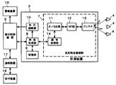
計測装置3は、図3のブロック図に示すように、反射物体観測部7と判定処理部8と記憶部9及び自己診断部10を有する。
As shown in the block diagram of FIG. 3, the
反射物体観測部7は、踏切道2に電磁波、例えばミリ波を照射し、各リフレクタ4からの反射波を受信して各リフレクタ4までの距離と反射強度を観測するものであり、IF(Intermediate Frequency)/BB(Base Band)部11とRF(Radio Frequency)部12とアンテナ13及び信号処理部14を有する。IF/BB部11は、レーダ方式に則して送信波を周波数変調させて中間周波信号を得てRF部12に送る。このレーダ方式は、物体の距離が検出できれば、FM(Frequency Modulated)−CW(Continuous Wave)方式やパルス方式あるいは2周波CW方式又はスペクトラム拡散方式の何れであっても良い。RF部12は、IF/BB部11で周波数変調した中間周波信号を、ミリ波帯の電力増幅及び周波数逓倍を行いアンテナ13に送る。アンテナ13は、RF部12からの三角波や正弦波、矩形波に周波数変調されたミリ波の送信信号を踏切道2に照射し、リフレクタ4からの反射波を受信する。また、RF部12は、アンテナ13で受信したリフレクタ4からの反射波を低雑音増幅してIF/BB部11に送る。IF/BB部11は、RF部12で受信した反射波と送信波を混合し、距離成分を含んだビート信号を得る。信号処理部14は、IF/BB部11で得たビート信号をサンプリングしてデジタル変換を行い、高速フーリエ演算からスペクトラム解析を用いて、周波数と受信電力強度(反射強度)のスペクトラムデータからミリ波の反射位置までの距離と反射強度を算出する。記憶部9にはあらかじめ計測装置3に対応するリフレクタ4までの距離が検知対象領域の範囲として記憶している。
The reflection
この反射物体観測部7のアンテナ13は、図1又は図2の配置図に示すように、照射したミリ波を反射するリフレクタ4の数に応じたペンシルビームアンテナを設けたり、水平方向のミリ波のビーム幅を広げて複数のリフレクタ4を検知するワイドビーム方式、又は、複数アンテナを電子的に切り替える電子スキャン方式の何れかを選択する。そしてアンテナ13から照射するミリ波の水平方向のビーム幅は隙間がないようにして、踏切道2内の全面を照射できるようにする。例えば図2に示すように、複々線の踏切でペンシルビーム方式のアンテナ13を使用した場合は、一方の計測装置3aのアンテナ13の各ペンシルビームアンテナから照射したミリ波のビーム15が互いに重なり合い、他方の計測装置3bのアンテナ13の各ペンシルビームアンテナから照射したミリ波のビーム15が互いに重なり合うようにして、計測装置3aと計測装置3bのアンテナ13から踏切道2の全面にビームを照射するようにする。また、アンテナ13から照射するミリ波の垂直方向のビーム幅は、図4に示すように、照射されたビーム15が車両19の車輪間をすり抜けないようにする。
As shown in the layout diagram of FIG. 1 or FIG. 2, the
判定処理部8は、踏切制御装置5の制御を受け、反射物体観測部7の信号処理部14から出力するミリ波の反射位置までの距離と反射強度を記憶部9に記憶し、反射位置までの距離と反射強度の変動から障害物の有無を判定して、判定結果を踏切制御装置5に出力する。
The
自己診断部10は、判定処理部8からミリ波の反射位置までの距離と反射強度を入力して計測装置3の異常の有無を診断して、診断結果を踏切制御装置5に出力するものであり、反射強度が自然変動に応じて定めた所定範囲内を一定時間逸脱し、かつ反射位置までの距離が検知対象領域である踏切道2内から逸脱した場合、計測装置3に異常が発生したと判定する。
The self-
踏切制御装置5は、計測装置3からの障害物判定処理結果や自己診断判定結果を入力し、踏切道2に障害物が存在することを検出したときや、計測装置3に異常が発生したとき、警報装置16に異常を知らせる信号を送り、警報装置16を発光させて報知し、その状況を通報装置17を介して保守装置18に送り管理者へ通報する。
The level
前記のように構成された計測装置3で踏切道2内の障害物の存在を検知するときの処理を図5のフローチャートを参照して説明する。
Processing when the presence of an obstacle in the
計測装置3の判定処理部8は、まず、図5に示すように、動作モードとして初期設定モードが設定されているか検知実行モードが設定されているかを確認し(ステップS1)、踏切制御装置5より動作モードとして初期設定モードが設定されると(ステップS2)、全ての処理をリセットして、反射物体観測部7に計測を開始させる(ステップS3)。反射物体観測部7は障害物がない状態で検知対象領域である踏切道2内にミリ波を照射し、その反射波を受信して検知対象領域内の基準反射物体である各リフレクタ4までの距離と反射強度を一定時間観測する(ステップS4)。すなわち、反射物体観測部7の信号処理部14はIF/BB部11に送信波を送る。IF/BB部11は送られた送信波を周波数変調して中間周波信号をRF部12に送る。RF部12は送られた中間周波信号によりミリ波を発生させてアンテナ13から踏切道2内に照射し、アンテナ13で受信した反射波を低雑音増幅してIF/BB部11に送る。IF/BB部11は、受信した反射波と送信波から距離成分を含んだビート信号を生成して信号処理部14に送る。信号処理部14は送られたビート信号をサンプリングしてデジタル変換を行い、各反射物までの距離と反射強度を算出して判定処理部8に送る。
First, as shown in FIG. 5, the
判定処理部8は送られた各反射物までの距離と反射強度のなかで検知対象領域内にある反射物すなわち各リフレクタ4の反射強度を選択し、観測した反射強度に対する所定の範囲を各リフレクタ4までの距離の変動許容範囲とともに障害物判定の背景情報として記憶部9に記録する(ステップS5)。この反射強度の範囲は、図6に示すように、計測装置3のアンテナ13から距離R0に設けられた1つのリフレクタ4の領域に照射するビーム15に注目して、観測された反射強度をP0とすると、自然変動を考慮した反射強度の最大値として(P0+n)、反射強度の最小値として(P0−n)を反射強度の範囲として記憶部9に記憶する。そして記憶部9に記録してある検知情報等を消去する(ステップS6)。
The
この状態で踏切制御装置5より動作モードとして検知実行モードが設定されると(ステップS7)、計測装置3は踏切道2内にミリ波を照射し、踏切道2内からの全ての反射波を受信して、受信した反射波の反射位置までの距離と反射強度を検出して判定処理部8に送る(ステップS8)。判定処理部8は送られた各反射位置までの距離と反射強度のなかから検出対象領域内の全ての反射位置までの距離と反射強度と、初期設定モードで記録した背景情報とを比較しその差を判定する(ステップS9)。この判定の結果、検知対象領域内の各反射位置までの距離と反射強度が背景情報と差がない場合、反射物体観測部7による各反射位置までの距離と反射強度の観測を、踏切道2の監視時間を考慮して例えば100ミリ秒の処理周期で繰り返す(ステップS10,S8)。
In this state, when the detection execution mode is set as the operation mode by the level crossing control device 5 (step S7), the measuring
この観測を続行して検出対象領域内の各反射位置までの距離と反射強度に背景情報と差が生じた場合(ステップS10)、障害物が存在する疑いが有るか、装置に異常が生じた疑い有りとして判定処理部8は判定処理を継続する。そして背景情報と差が生じた反射位置までの距離が背景情報に含まれる各リフレクタ4までの距離の変動許容範囲外であるかどうかを判定する(ステップS11)。この判定の結果、反射位置までの距離が各リフレクタ4までの距離の変動許容範囲外のときは、背景情報と差が生じた反射強度が背景情報に含まれる各リフレクタ4の反射強度の範囲以上であるかを判定する(ステップS12)。この判定の結果、反射位置までの距離が各リフレクタ4までの距離の変動許容範囲外で、背景情報と差が生じた反射強度が背景情報に含まれる各リフレクタ4の反射強度の範囲以上のとき、その検知情報を記憶部9に記録する(ステップS13)。
When this observation is continued and a difference from the background information occurs in the distance to each reflection position in the detection target region and the reflection intensity (step S10), there is a suspicion that an obstacle exists or an abnormality has occurred in the apparatus. The
例えば、図7に示すように、計測装置3のアンテナ13から距離R0に設けられた1つのリフレクタ4の領域に照射するビーム15に注目した場合、踏切道2を走行する車両19が水平方向のビーム15外の位置C0,C4に存在する場合は、図8の距離に対する受信強度分布の変化特性図に示すように、リフレクタ4までの距離R0に応じた反射強度P0だけが観測される。これに対して車両19がビーム15内の位置C1,C3に存在する場合は、リフレクタ4までの距離R0に対応した反射強度P0及び位置C1,C3までの距離に対応した反射強度が観測される。そして車両19が計測装置3に近い距離R1に存在する場合、観測する反射強度は最も高い反射強度P2となり、車両19が計測装置3から距離R1,R2,R0と離れるにしたがって観測される反射強度は反射強度P2,P1,P0と低くなる。したがって踏切道2内に車両19が存在する場合は、反射強度P2,P1が各リフレクタ4の反射強度の範囲(P0+n)以上になり、踏切道2に障害物が存在することになる。
For example, as shown in FIG. 7, when attention is paid to a
判定処理部8は、この処理を継続して行い、背景情報と差が生じた反射位置までの距離が各リフレクタ4までの距離の変動許容範囲外で、背景情報と差が生じた反射強度が背景情報に含まれる各リフレクタ4の反射強度の範囲以上になる検出回数を計数し(ステップS14)、所定時間経過したときに、検出回数が所定回数を超えているかどうかを判定する(ステップS15,S16)。この判定の結果、検出回数が所定回数を超えている場合、判定処理部8は踏切道2に静止した障害物や移動中の障害物が存在すると判定し(ステップS17)、障害物の検知時間と位置を示す障害物検出情報を記憶部9に記録して踏切制御装置5に送る(ステップS18)。
The
踏切制御装置5は障害物の検知情報を入力すると、警報装置16で踏切道2に障害物があることを報知させ、その状況を通報装置17を介して保守装置18に送り管理者に伝える。
When the level
また、背景情報と差が生じた反射位置までの距離が背景情報に含まれる各リフレクタ4までの距離の変動許容範囲外であるかどうかを判定した結果(ステップS11)、背景情報と差が生じた反射位置までの距離が背景情報に含まれる各リフレクタ4までの距離の変動許容範囲内であるとき、すなわち、リフレクタ4までの距離R0と反射強度だけが観測されているときに背景情報と差が生じているとき、自己診断部10は計測装置3に異常が発生したかどうかの自己診断処理に入る。自己診断部10は、判定処理部8で背景情報と差が生じた反射位置までの距離が背景情報に含まれる各リフレクタ4までの距離の変動許容範囲内であると判定すると、背景情報と差が生じた反射強度が背景情報に含まれる各リフレクタ4の反射強度の範囲内であるかを判定する(ステップS19)。この判定の結果、背景情報と差が生じた反射強度が背景情報に含まれる各リフレクタ4の反射強度の範囲外であるとき、反射強度の範囲外になる検出回数を計数し(ステップS20)、所定時間経過したときに、検出回数が所定回数を超えているかどうかを判定する(ステップS21,S22)。この判定の結果、検出回数が所定回数を超えている場合、自己診断部10は計測装置3に異常が生じたことを示す情報を踏切制御装置5に送る(ステップS23)。また、所定時間経過したときに、検出回数が所定回数を超えていない場合は、自己確認のため、計測装置3を自動的に一時的に初期設定モードにして基準背景を生成して検知処理を実行させる(ステップS24、S3)。
In addition, as a result of determining whether or not the distance to the reflection position where the difference from the background information occurs is outside the allowable fluctuation range of the distance to each
また、背景情報と差が生じた反射位置までの距離が背景情報に含まれる各リフレクタ4までの距離の変動許容範囲外であるかどうかを判定し(ステップS11)、この判定の結果、反射位置までの距離が各リフレクタ4までの距離の変動許容範囲外のとき、背景情報と差が生じた反射強度が背景情報に含まれる各リフレクタ4の反射強度の範囲以上であるかを判定した結果(ステップS12)、反射位置までの距離が各リフレクタ4までの距離の変動許容範囲外で、反射強度が背景情報に含まれる各リフレクタ4の反射強度の範囲内のときも、自己診断部10は自己診断処理に入り、反射位置までの距離が各リフレクタ4までの距離の変動許容範囲外で、反射強度が背景情報に含まれる各リフレクタ4の反射強度の範囲内になる検出回数を計数し(ステップS20)、所定時間経過したときに、検出回数が所定回数を超えているかどうかを判定する(ステップS21,S22)。この判定の結果、検出回数が所定回数を超えている場合、自己診断部10は計測装置3に異常が生じたことを示す情報を踏切制御装置5に送る(ステップS23)。
Further, it is determined whether or not the distance to the reflection position where the difference from the background information is outside the allowable fluctuation range of the distance to each
踏切制御装置5は計測装置3に異常が生じたことを示す情報を入力すると、計測装置3の処理を停止させ、警報装置16で異常を報知させ、その状況を通報装置17を介して保守装置18に送り管理者に伝える。
When the level
前記説明では計測装置3からミリ波帯の電磁波を制御対象領域に照射する場合について説明したが、ミリ波帯の電磁波を限定するものではなく、マイクロ波帯であっても良い。
In the above description, the millimeter wave band electromagnetic wave is irradiated from the measuring
また前記説明では、踏切道2の障害物を検知する場合について説明したが、例えば防犯用の侵入物体の検知にも同様にして適用することができる。
In the above description, the case of detecting an obstacle on the
1;軌道、2;踏切道、3;計測装置、4;リフレクタ、5;踏切制御装置、
6;踏切遮断機、7;反射物体観測部、8;判定処理部、9;記憶部、
10;自己診断部、11;IF/BB部、12;RF部、13;アンテナ、
14;信号処理部、16;警報装置、17;通報装置、18;保守装置。
1; track, 2; railroad crossing, 3; measuring device, 4; reflector, 5; railroad crossing control device,
6; Railroad crossing barrier, 7; Reflected object observation unit, 8; Judgment processing unit, 9; Storage unit,
10; Self-diagnosis unit, 11; IF / BB unit, 12; RF unit, 13; Antenna,
14; Signal processing unit, 16; Alarm device, 17; Notification device, 18; Maintenance device.
Claims (5)
前記計測装置は、反射物体観測手段と判定処理手段及び自己診断手段を有し、
前記反射物体観測手段は、検知対象領域に電磁波を照射して前記基準反射体と反射物体からの反射波を受信し、受信した反射波から前記基準反射体と反射物体までの距離と反射強度を観測し、
前記判定処理手段は、初期設定モードで、前記反射物体観測手段から検知対象領域に電磁波を照射し、前記基準反射物体までの距離と反射強度を観測し、観測した反射強度に対する所定の範囲と前記基準反射体までの距離の変動許容範囲を障害物判定の背景情報として記憶し、
検知実行モードでは、前記反射物体観測手段で観測した反射波の反射位置までの距離と反射強度のなかから検出対象領域内の全ての反射位置までの距離と反射強度と背景情報とを比較し、各反射位置までの距離と反射強度に背景情報と差が生じた反射位置までの距離が背景情報に含まれる前記基準反射体までの距離の変動許容範囲外であるかどうかを判定し、反射位置までの距離が前記基準反射体までの距離の変動許容範囲外のとき背景情報と差が生じた反射強度が背景情報に含まれる前記基準反射体の反射強度の範囲以上であるかを判定する処理を継続して行い、背景情報と差が生じた反射位置までの距離が前記基準反射体までの距離の変動許容範囲外で、背景情報と差が生じた反射強度が背景情報に含まれる前記基準反射体の反射強度の範囲以上になる検出回数を計数し、所定時間経過したときに検出回数が所定回数を超えている場合、検出対象領域に障害物が存在すると判定し、
前記自己診断手段は、前記判定処理手段で背景情報と差が生じた反射位置までの距離が背景情報に含まれる前記基準反射体までの距離の変動許容範囲内であり、かつ、背景情報と差が生じた反射強度が背景情報に含まれる前記基準反射体の反射強度の範囲外であるとき、反射強度の範囲外になる検出回数を計数し、所定時間経過したときに、検出回数が所定回数を超えているとき装置異常と判定することを特徴とする障害物検知装置。 A measuring device and one or a plurality of reference reflectors arranged as reflection reference points at predetermined positions in the detection target region;
The measuring device includes a reflecting object observation unit, a determination processing unit, and a self-diagnosis unit,
The reflecting object observing means irradiates an electromagnetic wave to a detection target region to receive a reflected wave from the reference reflector and the reflecting object, and calculates a distance and a reflection intensity from the received reflected wave to the reference reflector and the reflecting object. Observe
In the initial setting mode, the determination processing unit irradiates an electromagnetic wave to the detection target region from the reflection object observation unit, observes a distance to the reference reflection object and a reflection intensity, a predetermined range with respect to the observed reflection intensity, and the Memorize the fluctuation tolerance of the distance to the reference reflector as background information for obstacle determination,
In the detection execution mode, the distance to the reflection position of the reflected wave observed by the reflecting object observation means and the reflection intensity from the distance to all the reflection positions in the detection target region, the reflection intensity, and the background information are compared. It is determined whether the distance to each reflection position and the distance to the reflection position where the reflection intensity differs from the background information are outside the allowable fluctuation range of the distance to the reference reflector included in the background information. When the distance to the reference reflector is outside the allowable fluctuation range of the distance to the reference reflector, it is determined whether the reflection intensity that is different from the background information is equal to or greater than the reflection intensity range of the reference reflector included in the background information The reference information in which the distance to the reflection position where the difference from the background information occurs is outside the allowable fluctuation range of the distance to the reference reflector, and the reflection intensity that is different from the background information is included in the background information. Of reflection intensity of reflector Counts the number of detection times made on囲以, it determines that the number of detection times when a predetermined time has elapsed if it exceeds the predetermined number of times, there is an obstacle in the detection target area,
The self-diagnostic means is such that the distance to the reflection position where the difference from the background information has occurred in the determination processing means is within the allowable variation range of the distance to the reference reflector included in the background information, and is different from the background information. When the reflection intensity that occurs is outside the range of the reflection intensity of the reference reflector included in the background information, the number of detections that are outside the range of the reflection intensity is counted. An obstacle detection device characterized by determining that the device is abnormal when exceeding .
検知実行モードでは、検知対象領域に電磁波を照射して観測した反射波の反射位置までの距離と反射強度のなかから検出対象領域内の全ての反射位置までの距離と反射強度と背景情報とを比較し、各反射位置までの距離と反射強度に背景情報と差が生じた反射位置までの距離が背景情報に含まれる前記基準反射体までの距離の変動許容範囲外であるかどうかを判定し、反射位置までの距離が前記基準反射体までの距離の変動許容範囲外のとき背景情報と差が生じた反射強度が背景情報に含まれる前記基準反射体の反射強度の範囲以上であるかを判定する処理を継続して行い、背景情報と差が生じた反射位置までの距離が前記基準反射体までの距離の変動許容範囲外で、背景情報と差が生じた反射強度が背景情報に含まれる前記基準反射体の反射強度の範囲以上になる検出回数を計数し、所定時間経過したときに検出回数が所定回数を超えている場合、検出対象領域に障害物が存在すると判定し、In the detection execution mode, the distance, reflection intensity, and background information from the distance to the reflection position of the reflected wave observed by irradiating the electromagnetic wave to the detection area and the reflection intensity to all the reflection positions in the detection area. Comparison is made to determine whether the distance to each reflection position and the distance to the reflection position where the reflection intensity differs from the background information are outside the allowable range of the distance to the reference reflector included in the background information. When the distance to the reflection position is outside the allowable fluctuation range of the distance to the reference reflector, the reflection intensity that is different from the background information is greater than or equal to the reflection intensity range of the reference reflector included in the background information. The determination process is continued, and the distance to the reflection position where the difference from the background information is outside the allowable fluctuation range of the distance to the reference reflector, and the reflection intensity including the difference from the background information is included in the background information. The reference reflector is Counts the number of detections made over a range of intensities, it is determined that the detected number of times when a predetermined time has elapsed if it exceeds the predetermined number of times, there is an obstacle in the detection target area,
前記背景情報と差が生じた反射位置までの距離が背景情報に含まれる前記基準反射体までの距離の変動許容範囲内であり、かつ、背景情報と差が生じた反射強度が背景情報に含まれる前記基準反射体の反射強度の範囲外であるとき、反射強度の範囲外になる検出回数を計数し、所定時間経過したときに、検出回数が所定回数を超えているとき装置異常と判定することを特徴とする障害物検知方法。The distance to the reflection position where the difference from the background information is within the allowable variation range of the distance to the reference reflector included in the background information, and the reflection intensity where the difference from the background information is included in the background information Counts the number of detections that are outside the range of the reflection intensity when the reference reflector is out of the range, and determines that the device is abnormal when the number of detections exceeds the predetermined number when a predetermined time has elapsed. An obstacle detection method characterized by that.
Priority Applications (1)
| Application Number | Priority Date | Filing Date | Title |
|---|---|---|---|
| JP2004039132A JP4080435B2 (en) | 2004-02-17 | 2004-02-17 | Obstacle detection device and detection method |
Applications Claiming Priority (1)
| Application Number | Priority Date | Filing Date | Title |
|---|---|---|---|
| JP2004039132A JP4080435B2 (en) | 2004-02-17 | 2004-02-17 | Obstacle detection device and detection method |
Publications (3)
| Publication Number | Publication Date |
|---|---|
| JP2005233615A JP2005233615A (en) | 2005-09-02 |
| JP2005233615A5 JP2005233615A5 (en) | 2005-12-15 |
| JP4080435B2 true JP4080435B2 (en) | 2008-04-23 |
Family
ID=35016754
Family Applications (1)
| Application Number | Title | Priority Date | Filing Date |
|---|---|---|---|
| JP2004039132A Expired - Lifetime JP4080435B2 (en) | 2004-02-17 | 2004-02-17 | Obstacle detection device and detection method |
Country Status (1)
| Country | Link |
|---|---|
| JP (1) | JP4080435B2 (en) |
Families Citing this family (20)
| Publication number | Priority date | Publication date | Assignee | Title |
|---|---|---|---|---|
| JP4339146B2 (en) * | 2004-02-18 | 2009-10-07 | 日本信号株式会社 | Railroad crossing obstacle detection device |
| JP2008179269A (en) * | 2007-01-25 | 2008-08-07 | Mitsubishi Electric Corp | Crossing obstacle detector |
| JP5224723B2 (en) * | 2007-05-18 | 2013-07-03 | 三菱電機特機システム株式会社 | Microwave detection system and microwave detection method |
| JP5134453B2 (en) * | 2008-06-25 | 2013-01-30 | 日本信号株式会社 | Railroad crossing obstacle detection device |
| JP5498682B2 (en) * | 2008-10-17 | 2014-05-21 | 日本信号株式会社 | Railroad crossing obstacle detection device |
| JP5302620B2 (en) * | 2008-10-17 | 2013-10-02 | 日本信号株式会社 | Railroad crossing obstacle detection device |
| JP5436256B2 (en) * | 2010-02-15 | 2014-03-05 | 株式会社レッツ・コーポレーション | Monitoring system |
| JP5872151B2 (en) * | 2010-11-09 | 2016-03-01 | 日本信号株式会社 | Railroad crossing obstacle detection device |
| JP5872152B2 (en) * | 2010-11-09 | 2016-03-01 | 日本信号株式会社 | Railroad crossing obstacle detection device |
| JP6005052B2 (en) * | 2012-02-29 | 2016-10-12 | パナソニック株式会社 | Intruder detection apparatus and intruder detection method |
| JP6102460B2 (en) * | 2013-04-23 | 2017-03-29 | 富士通株式会社 | Detection system, detection device, detection program, and detection method |
| JP6772524B2 (en) * | 2016-04-21 | 2020-10-21 | 住友電気工業株式会社 | Radio sensor and detection method |
| JP6774139B2 (en) * | 2016-08-24 | 2020-10-21 | 大同信号株式会社 | Railroad crossing obstacle detection device |
| JP6722128B2 (en) * | 2017-03-01 | 2020-07-15 | 株式会社日立製作所 | Presence detection system and presence detection device |
| DE102018207716A1 (en) * | 2018-05-17 | 2019-11-21 | Robert Bosch Gmbh | Radar sensor system and method of manufacturing a radar sensor system |
| JP7349783B2 (en) * | 2018-12-21 | 2023-09-25 | 大同信号株式会社 | Level crossing obstacle detection device |
| DE102019111679A1 (en) * | 2019-05-06 | 2020-11-12 | S.M.S Smart Microwave Sensors Gmbh | Procedure for recording road users |
| CN113552589A (en) * | 2020-04-01 | 2021-10-26 | 杭州萤石软件有限公司 | Obstacle detection method, robot, and storage medium |
| WO2023112635A1 (en) * | 2021-12-17 | 2023-06-22 | 住友電気工業株式会社 | Infrastructure radio wave sensor |
| CN114739451A (en) * | 2022-03-22 | 2022-07-12 | 国网山东省电力公司超高压公司 | Transmission conductor safety early warning method under millimeter wave radar monitoring |
Family Cites Families (6)
| Publication number | Priority date | Publication date | Assignee | Title |
|---|---|---|---|---|
| JP4007707B2 (en) * | 1998-12-18 | 2007-11-14 | 東日本旅客鉄道株式会社 | Obstacle detection device for railway |
| JP2001325690A (en) * | 2000-05-18 | 2001-11-22 | Nippon Signal Co Ltd:The | Obstacle detector |
| JP3651769B2 (en) * | 2000-06-14 | 2005-05-25 | 株式会社東芝 | Aircraft detection system |
| JP3371900B2 (en) * | 2000-12-01 | 2003-01-27 | オムロン株式会社 | Intruding object detection method and intruding object detection system |
| JP3443645B2 (en) * | 2001-03-06 | 2003-09-08 | 国土交通省国土技術政策総合研究所長 | Data confidence judgment method for millimeter wave sensor |
| JP2003011824A (en) * | 2001-06-29 | 2003-01-15 | East Japan Railway Co | Crossing obstructing detector |
-
2004
- 2004-02-17 JP JP2004039132A patent/JP4080435B2/en not_active Expired - Lifetime
Also Published As
| Publication number | Publication date |
|---|---|
| JP2005233615A (en) | 2005-09-02 |
Similar Documents
| Publication | Publication Date | Title |
|---|---|---|
| JP4080435B2 (en) | Obstacle detection device and detection method | |
| US5471214A (en) | Collision avoidance and warning system | |
| US8596587B2 (en) | Systems and methods for redundant vehicle detection at highway-rail grade crossings | |
| US6680689B1 (en) | Method for determining object classification from side-looking sensor data | |
| US9019115B2 (en) | Warning horn control system, radar system, and method | |
| JP2007126025A (en) | Object detection unit, object detector, and device and program for detecting moving object in crosscut | |
| US20200118430A1 (en) | System, method and computer program product for radar based car accident prevention | |
| JP4731517B2 (en) | Railroad crossing obstacle detection device | |
| JP3909370B2 (en) | Security sensor | |
| JP4117581B2 (en) | Crossing obstacle detection device | |
| JP4387827B2 (en) | Railroad crossing obstacle detection device | |
| KR101238702B1 (en) | Detection Apparatus on Railroad Crossing Using Detector For Reliability And Method Using The Apparatus | |
| US20140118170A1 (en) | Vehicle detector | |
| WO2003029045A2 (en) | Multi-technology object detection system and method | |
| JP4169677B2 (en) | Obstacle detection device | |
| JP4339146B2 (en) | Railroad crossing obstacle detection device | |
| JP3324537B2 (en) | Vehicle monitoring device | |
| JP5057831B2 (en) | Obstacle detection device | |
| JP3854558B2 (en) | Level crossing obstacle detection device and level crossing obstacle detection method | |
| JP2008179269A (en) | Crossing obstacle detector | |
| JPH05274035A (en) | Obstacle detector | |
| JP2012101620A (en) | Railroad-crossing obstacle detector | |
| JP4738374B2 (en) | Railroad crossing obstacle detection device | |
| JP3775191B2 (en) | Pedestrian presence notification device and on-vehicle pedestrian detection device | |
| RU2330774C2 (en) | Device to prevent emergency conditions at railway crossings |
Legal Events
| Date | Code | Title | Description |
|---|---|---|---|
| A521 | Request for written amendment filed |
Free format text: JAPANESE INTERMEDIATE CODE: A523 Effective date: 20051026 |
|
| A621 | Written request for application examination |
Free format text: JAPANESE INTERMEDIATE CODE: A621 Effective date: 20051026 |
|
| A977 | Report on retrieval |
Free format text: JAPANESE INTERMEDIATE CODE: A971007 Effective date: 20070705 |
|
| A131 | Notification of reasons for refusal |
Free format text: JAPANESE INTERMEDIATE CODE: A131 Effective date: 20070710 |
|
| A521 | Request for written amendment filed |
Free format text: JAPANESE INTERMEDIATE CODE: A523 Effective date: 20070820 |
|
| TRDD | Decision of grant or rejection written | ||
| A01 | Written decision to grant a patent or to grant a registration (utility model) |
Free format text: JAPANESE INTERMEDIATE CODE: A01 Effective date: 20080205 |
|
| A61 | First payment of annual fees (during grant procedure) |
Free format text: JAPANESE INTERMEDIATE CODE: A61 Effective date: 20080206 |
|
| FPAY | Renewal fee payment (event date is renewal date of database) |
Free format text: PAYMENT UNTIL: 20110215 Year of fee payment: 3 |
|
| R150 | Certificate of patent or registration of utility model |
Ref document number: 4080435 Country of ref document: JP Free format text: JAPANESE INTERMEDIATE CODE: R150 Free format text: JAPANESE INTERMEDIATE CODE: R150 |
|
| FPAY | Renewal fee payment (event date is renewal date of database) |
Free format text: PAYMENT UNTIL: 20120215 Year of fee payment: 4 |
|
| R250 | Receipt of annual fees |
Free format text: JAPANESE INTERMEDIATE CODE: R250 |
|
| FPAY | Renewal fee payment (event date is renewal date of database) |
Free format text: PAYMENT UNTIL: 20120215 Year of fee payment: 4 |
|
| FPAY | Renewal fee payment (event date is renewal date of database) |
Free format text: PAYMENT UNTIL: 20130215 Year of fee payment: 5 |
|
| R250 | Receipt of annual fees |
Free format text: JAPANESE INTERMEDIATE CODE: R250 |
|
| FPAY | Renewal fee payment (event date is renewal date of database) |
Free format text: PAYMENT UNTIL: 20140215 Year of fee payment: 6 |
|
| R250 | Receipt of annual fees |
Free format text: JAPANESE INTERMEDIATE CODE: R250 |
|
| R250 | Receipt of annual fees |
Free format text: JAPANESE INTERMEDIATE CODE: R250 |
|
| R250 | Receipt of annual fees |
Free format text: JAPANESE INTERMEDIATE CODE: R250 |
|
| R250 | Receipt of annual fees |
Free format text: JAPANESE INTERMEDIATE CODE: R250 |
|
| R250 | Receipt of annual fees |
Free format text: JAPANESE INTERMEDIATE CODE: R250 |
|
| R250 | Receipt of annual fees |
Free format text: JAPANESE INTERMEDIATE CODE: R250 |
|
| R250 | Receipt of annual fees |
Free format text: JAPANESE INTERMEDIATE CODE: R250 |
|
| S111 | Request for change of ownership or part of ownership |
Free format text: JAPANESE INTERMEDIATE CODE: R313117 |
|
| R350 | Written notification of registration of transfer |
Free format text: JAPANESE INTERMEDIATE CODE: R350 |
|
| R250 | Receipt of annual fees |
Free format text: JAPANESE INTERMEDIATE CODE: R250 |
|
| R250 | Receipt of annual fees |
Free format text: JAPANESE INTERMEDIATE CODE: R250 |
|
| R250 | Receipt of annual fees |
Free format text: JAPANESE INTERMEDIATE CODE: R250 |
|
| R250 | Receipt of annual fees |
Free format text: JAPANESE INTERMEDIATE CODE: R250 |
|
| R250 | Receipt of annual fees |
Free format text: JAPANESE INTERMEDIATE CODE: R250 |
|
| EXPY | Cancellation because of completion of term |