JP4075397B2 - Vehicle front-end structure - Google Patents
Vehicle front-end structure Download PDFInfo
- Publication number
- JP4075397B2 JP4075397B2 JP2002037869A JP2002037869A JP4075397B2 JP 4075397 B2 JP4075397 B2 JP 4075397B2 JP 2002037869 A JP2002037869 A JP 2002037869A JP 2002037869 A JP2002037869 A JP 2002037869A JP 4075397 B2 JP4075397 B2 JP 4075397B2
- Authority
- JP
- Japan
- Prior art keywords
- radiator
- duct
- shroud
- vehicle
- end structure
- Prior art date
- Legal status (The legal status is an assumption and is not a legal conclusion. Google has not performed a legal analysis and makes no representation as to the accuracy of the status listed.)
- Expired - Fee Related
Links
Images


Description
【0001】
【発明の属する技術分野】
本発明は、車両のフロントエンド構造に関するものである。
【0002】
【従来の技術及び発明が解決しようとする課題】
一般的な、車両のフロントエンド構造では、送風機にて誘起された風がラジエータを迂回して流れることを防止するためにシュラウドを設けているが、このシュラウドは、ラジエータと送風機と繋ぐ一種の空気通路を構成するものであるので、送風機にて誘起された風は確実にラジエータを通過するものの、ラジエータと車両ボディとの隙間を流れてしまう走行風まではラジエータに導くことができない。
【0003】
そこで、発明者等は、図3に示すように、シュラウド41の端部のうちラジエータ10側の端部を、ラジエータ10を越えて風上側である車両前方側まで延長するダクト部42をシュラウド41に一体形成することにより、従来、ラジエータと車両ボディとの隙間を流れてラジエータを迂回していた空気をラジエータに導き、ラジエータの冷却能力の向上を図ったフロントエンド構造を検討したが、以下に述べる問題が新たに発生した。
【0004】
すなわち、ラジエータは内部に冷却水が充満しているので、冷却水を含めたラジエータの質量は大きい。このため、車両振動によりラジエータが振動すると車両全体に大きな振動が発生するとともに、ラジエータ自体が振動により疲労破壊するおそれがある。
【0005】
そこで、通常、ラジエータをゴム等の弾性部材を介して車両ボディに固定することにより、ラジエータの振動を吸収するとともに、ラジエータを動吸振器の錘として作用させることによりエンジン振動等の車両振動を吸収している。
【0006】
このため、図4に示すように、ダクト部42に弾性部材50との干渉を避けるための切り欠きを設ける、又はダクト部42とラジエータ10との間にラジエータを装着することができる程度の隙間を設けるといった手段を講ずる必要が発生してしまった。
【0007】
そして、この切り欠き又は隙間を通って空気がラジエータを迂回して流れてしまうため、ダクト部を設けてもラジエータの冷却能力を十分に向上させることができなかった。
【0008】
また、切り欠き又は隙間を通って空気がラジエータを迂回して流れてしまうことを防止すべく、切り欠き又は隙間を小さくすると、ラジエータの車両への組み付け性が悪化し、フロントエンド構造部の組み付け工数の増大を招いてしまうという問題が新たに発生する。
【0009】
本発明は、上記点に鑑み、上記問題を解決しつつ、ダクト部をシュラウドに一体形成してラジエータの冷却能力の向上させることを目的とする。
【0010】
【課題を解決するための手段】
本発明は、上記目的を達成するために、請求項1に記載の発明では、ラジエータ(10)に冷却風を送風する送風機(30)と、送風機(30)にて誘起された風がラジエータ(10)を迂回して流れることを防止するシュラウド(41)、及びラジエータ(10)の外周部の全周を覆うとともに、内部がシュラウド(41)と連続的に繋がったダクト部(42)が一部材として一体形成されたダクトシュラウド(40)とを備え、ダクト部(42)は、ラジエータ(10)の外周部の全周にわたって、ラジエータ(10)を超えて車両後方側から車両前方側へと延びており、ラジエータ(10)はダクトシュラウド(40)に固定され、さらに、ダクトシュラウド(40)は、弾性部材(50)を介して車両ボディ側に固定されていることを特徴とする。
【0011】
これにより、ダクト部(42)に弾性部材(50)との干渉を避けるための切り欠きを設ける、又はダクト部(42)とラジエータ(10)との間にラジエータ(10)を装着することができる程度の隙間を設けるといった手段を講ずる必要がない。
【0012】
したがって、切り欠き又は隙間を通って空気がラジエータ(10)を迂回して流れてしまうといった問題は原理的に発生しないので、フロントエンド構造の組み付け工数増を招くことなく、ラジエータ(10)の冷却能力の向上させることができる。
【0013】
なお、請求項2に記載の発明のごとく、ラジエータ(10)は、車両ボディに対してダクトシュラウド(40)に同位相にて振動変位するように、ダクトシュラウド(40)に一体化されることが望ましい。
【0014】
また、請求項3に記載の発明のごとく、弾性部材(50)は、ダクトシュラウド(40)のうちダクト部(42)の上下両端側に設けられたピン状の取り付け部(43)に装着されることが望ましい。また、請求項4に記載の発明の如く、ラジエータ(10)はダクトシュラウド(40)に締結固定されていることが望ましい。さらに、請求項5に記載の発明のごとく、ラジエータ(10)はダクト部(42)に車両後方側から締結固定されていることが望ましい。
【0015】
因みに、上記各手段の括弧内の符号は、後述する実施形態に記載の具体的手段との対応関係を示す一例である。
【0016】
【発明の実施の形態】
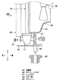
図1は本実施形態に係る車両のフロントエンド構造を示す分解斜視図であり、図2はラジエータとダクトシュラウドとの固定構造を示す模式図である。
【0017】
図1中、ラジエータ10はエンジン冷却水と空気とを熱交換する熱交換器であり、ラジエータ10の風上側には、空調装置の室外熱交換器であるコンデンサ20が搭載される。なお、コンデンサ20は、図2に示すように、ボルト21等の機械的締結手段によりラジエータ10のヘッダタンク11に着脱可能に固定されている。
【0018】
送風機30は、ラジエータ10より風下側に配置されてラジエータ10及びコンデンサ20に冷却風を送風する軸流ファン方式のものであり、シュラウド41は、送風機30の外周側及びラジエータ10と送風機30との隙間を覆うようにして、送風機30にて誘起された風がラジエータ10を迂回して流れることを防止する一種のカバーであり、送風機30はシュラウド41を介して車両ボディに固定される。
【0019】
ダクト部42は、図1に示すように、ラジエータ10及びコンデンサ20の外周部を覆うようにして、シュラウド41の端部のうちラジエータ10側端部を、ラジエータ10を越えて風上側である車両前方側まで延長した矩形パイプ状のものであり、その内部は、図2に示すように、シュラウド41と連続的に繋がっている。
【0020】
そして、本実施形態では、シュラウド41及びダクト部42を炭素繊維やガラス繊維等にて機械的強度が強化された樹脂にて一体成形することにより両者41、42を一体化している。以下、この一体化されたものをダクトシュラウド40と呼ぶ。
【0021】
また、ラジエータ10は、ボルト12等の機械的締結手段によりダクトシュラウド40のダクト部42に一体化されている。つまり、ラジエータ10は、ダクトシュラウド40に対して一体化されているため、ラジエータ10は車両ボディに対してダクトシュラウド40に同位相にて振動変位することとなる。
【0022】
一方、ダクトシュラウド40のダクト部42には、ゴム等の弾性材料からなる弾性部材としてのグロメット50を装着するためのピン状の取り付け部43が一体形成されている。
【0023】
なお、取り付け部43は、ダクト部42の上下両端側それぞれに2カ所、合計4カ所設けられおり、図1に示すように、下端側のグロメット50は車両ボディの一部をなすロアメンバー61に形成された装着穴61aに挿入装着され、一方、上端側のグロメット50は車両ボディの一部をなすアッパーメンバー62に形成された装着穴62aに挿入装着される。
【0024】
因みに、ロアメンバー61は車両ボディの一部をなすサイドメンバー63にボルト又は溶接にて固定され、アッパメンバー62は、下端側のグロメット50を装着穴61aに挿入装着した後、上端側のグロメット50が装着穴62aに挿入されるようにして車両ボディにボルトにて固定する。
【0025】
次に、本実施形態の作用効果を述べる。
【0026】
上記した構成により、ラジエータ10が固定されたダクトシュラウド40がグロメット50を介して車両ボディ側に固定される構造となるので、図1、2から明らかなように、ダクト部42にグロメット50との干渉を避けるための切り欠きを設ける、又はダクト部42とラジエータ10との間にラジエータ10を装着することができる程度の隙間を設けるといった手段を講ずる必要がない。
【0027】
したがって、切り欠き又は隙間を通って空気がラジエータ10を迂回して流れてしまうといった問題は原理的に発生しないので、フロントエンド構造の組み付け工数増を招くことなく、ラジエータ10の冷却能力の向上させることができる。
【0028】
(その他の実施形態)
上述の実施形態では、ダクトシュラウド40を樹脂にて一体成形したが、本発明はこれに限定されるものではなく、例えばアルミダイカスト等の金属鍛造、又はプレス成形等の塑性加工にて一体形成する等してもよい。
【0029】
また、上述の実施形態では、送風機30はラジエータ10の風下側に設置されていたが、本発明はこれに限定されるものではなく、送風機30をラジエータ10の風上側に設置しもよい。
【0030】
また、上述の実施形態では、軸流ファンを用いた送風機30を採用したが、本発明はこれに限定されるものではなく、例えば貫流ファンにて送風機30を構成しもよい。なお、軸流ファン及び貫流ファンの定義は、JIS B 0132による。
【0031】
また、上述の実施形態では、グロメット50はダクトシュラウド40に装着されていたが、本発明はこれに限定されるものではなく、車両ボディ側にグロメット50を装着した状態で、グロメット50を介してダクトシュラウド40を車両ボディに固定してもよい。
【図面の簡単な説明】
【図1】本発明の実施形態に係る車両のフロントエンド構造を示す分解斜視図である。
【図2】本発明の実施形態に係るラジエータとダクトシュラウドとの固定構造を示す模式図である。
【図3】検討品に係るラジエータとダクトシュラウドとの固定構造を示す模式図である。
【図4】検討品に係るラジエータとダクトシュラウドとの固定構造を示す斜視図である。
【符号の説明】
30…送風機、40…ダクトシュラウド、41…シュラウド、
42…ダクト部、50…グロメット。[0001]
BACKGROUND OF THE INVENTION
The present invention relates to a front end structure of a vehicle.
[0002]
[Prior art and problems to be solved by the invention]
In a general vehicle front-end structure, a shroud is provided to prevent wind induced by the blower from flowing around the radiator, but this shroud is a kind of air that connects the radiator and the blower. Since it constitutes a passage, the wind induced by the blower surely passes through the radiator, but the traveling wind that flows through the gap between the radiator and the vehicle body cannot be guided to the radiator.
[0003]
Therefore, the inventors, as shown in FIG. 3, provide a
[0004]
That is, since the radiator is filled with cooling water, the mass of the radiator including the cooling water is large. For this reason, when the radiator vibrates due to the vehicle vibration, a large vibration is generated in the entire vehicle, and the radiator itself may be fatigued due to the vibration.
[0005]
Therefore, usually, the radiator is fixed to the vehicle body via an elastic member such as rubber to absorb the vibration of the radiator, and the radiator acts as a weight of the dynamic vibration absorber to absorb the vehicle vibration such as the engine vibration. is doing.
[0006]
Therefore, as shown in FIG. 4, a gap is provided so that a notch for avoiding interference with the
[0007]
Since air flows around the radiator through the notches or gaps, the cooling capacity of the radiator cannot be sufficiently improved even if the duct portion is provided.
[0008]
Also, if the notch or gap is made small to prevent air from flowing around the radiator through the notch or gap, the assembly of the radiator to the vehicle will deteriorate, and the assembly of the front end structure will be reduced. There is a new problem of increasing man-hours.
[0009]
In view of the above points, an object of the present invention is to improve the cooling capacity of a radiator by integrally forming a duct portion on a shroud while solving the above problems.
[0010]
[Means for Solving the Problems]
In order to achieve the above object, according to the present invention, a blower (30) that blows cooling air to a radiator (10) and a wind induced by the blower (30) are arranged in a radiator (10). shroud to prevent flow to bypass the 10) (41), and covers the entire outer peripheral portion of the radiator (10), the duct part inside continuously connected with the shroud (41) (42) is one A duct shroud (40) integrally formed as a member , and the duct portion (42) extends from the vehicle rear side to the vehicle front side over the radiator (10) over the entire circumference of the radiator (10). extending and radiator (10) is fixed to the duct shroud (40), further duct shroud (40), that are fixed to the vehicle body side via an elastic member (50) And features.
[0011]
Thereby, a notch for avoiding interference with the elastic member (50) is provided in the duct part (42), or the radiator (10) is mounted between the duct part (42) and the radiator (10). There is no need to take measures such as providing a gap as much as possible.
[0012]
Therefore, since the problem that air flows around the radiator (10) through the notch or the gap does not occur in principle, the cooling of the radiator (10) is not caused without increasing the number of assembling steps of the front end structure. Ability can be improved.
[0013]
As in the second aspect of the invention, the radiator (10) is integrated with the duct shroud (40) so as to vibrate and displace in the same phase as the duct shroud (40) with respect to the vehicle body. Is desirable.
[0014]
Further, as in the third aspect of the present invention, the elastic member (50) is attached to the pin-shaped attachment portions (43) provided on the upper and lower ends of the duct portion (42) of the duct shroud (40). It is desirable. Further, as in the invention described in claim 4, it is desirable that the radiator (10) is fastened and fixed to the duct shroud (40) . Furthermore, as in the invention described in claim 5, La Jieta (10) it is desirably are fastened from the rear side of the vehicle to the duct portion (42).
[0015]
Incidentally, the reference numerals in parentheses of each means described above are an example showing the correspondence with the specific means described in the embodiments described later.
[0016]
DETAILED DESCRIPTION OF THE INVENTION
FIG. 1 is an exploded perspective view showing a front end structure of a vehicle according to the present embodiment, and FIG. 2 is a schematic view showing a fixing structure between a radiator and a duct shroud.
[0017]
In FIG. 1, a
[0018]
The
[0019]
As shown in FIG. 1, the
[0020]
In the present embodiment, the
[0021]
The
[0022]
On the other hand, the
[0023]
There are two
[0024]
Incidentally, the
[0025]
Next, the function and effect of this embodiment will be described.
[0026]
With the above-described configuration, the
[0027]
Therefore, since the problem that air flows around the
[0028]
(Other embodiments)
In the above-described embodiment, the
[0029]
Moreover, in the above-mentioned embodiment, although the
[0030]
Moreover, in the above-mentioned embodiment, although the
[0031]
In the above-described embodiment, the
[Brief description of the drawings]
FIG. 1 is an exploded perspective view showing a front end structure of a vehicle according to an embodiment of the present invention.
FIG. 2 is a schematic diagram showing a fixing structure between a radiator and a duct shroud according to the embodiment of the present invention.
FIG. 3 is a schematic view showing a fixing structure between a radiator and a duct shroud according to a product under study.
FIG. 4 is a perspective view showing a fixing structure between a radiator and a duct shroud according to an investigation product.
[Explanation of symbols]
30 ... Blower, 40 ... Duct shroud, 41 ... Shroud,
42 ... duct part, 50 ... grommet.
Claims (5)
前記送風機(30)にて誘起された風が前記ラジエータ(10)を迂回して流れることを防止するシュラウド(41)、及び前記ラジエータ(10)の外周部の全周を覆うとともに、内部が前記シュラウド(41)と連続的に繋がったダクト部(42)が一部材として一体形成されたダクトシュラウド(40)とを備え、
前記ダクト部(42)は、前記ラジエータ(10)の外周部の全周にわたって、前記ラジエータ(10)を超えて車両後方側から車両前方側へと延びており、
前記ラジエータ(10)は前記ダクトシュラウド(40)に固定され、
さらに、前記ダクトシュラウド(40)は、弾性部材(50)を介して車両ボディ側に固定されていることを特徴とする車両のフロントエンド構造。A blower (30) for blowing cooling air to the radiator (10);
The shroud (41) prevents the wind induced by the blower (30) from flowing around the radiator (10), and covers the entire circumference of the outer periphery of the radiator (10). A duct part (42) continuously connected to the shroud (41), and a duct shroud (40) integrally formed as one member ;
The duct portion (42) extends from the vehicle rear side to the vehicle front side over the radiator (10) over the entire circumference of the outer periphery of the radiator (10),
The radiator (10) is fixed to the duct shroud (40),
Further, the vehicle front end structure is characterized in that the duct shroud (40) is fixed to the vehicle body side via an elastic member (50).
Priority Applications (2)
| Application Number | Priority Date | Filing Date | Title |
|---|---|---|---|
| JP2002037869A JP4075397B2 (en) | 2002-02-15 | 2002-02-15 | Vehicle front-end structure |
| DE10233626.1A DE10233626B4 (en) | 2001-07-25 | 2002-07-24 | Front end construction for a vehicle |
Applications Claiming Priority (1)
| Application Number | Priority Date | Filing Date | Title |
|---|---|---|---|
| JP2002037869A JP4075397B2 (en) | 2002-02-15 | 2002-02-15 | Vehicle front-end structure |
Publications (3)
| Publication Number | Publication Date |
|---|---|
| JP2003237628A JP2003237628A (en) | 2003-08-27 |
| JP2003237628A5 JP2003237628A5 (en) | 2005-08-25 |
| JP4075397B2 true JP4075397B2 (en) | 2008-04-16 |
Family
ID=27779336
Family Applications (1)
| Application Number | Title | Priority Date | Filing Date |
|---|---|---|---|
| JP2002037869A Expired - Fee Related JP4075397B2 (en) | 2001-07-25 | 2002-02-15 | Vehicle front-end structure |
Country Status (1)
| Country | Link |
|---|---|
| JP (1) | JP4075397B2 (en) |
Families Citing this family (6)
| Publication number | Priority date | Publication date | Assignee | Title |
|---|---|---|---|---|
| FR2899557A3 (en) * | 2006-04-06 | 2007-10-12 | Renault Sas | Technical front face assembling arrangement for motor vehicle, has upper crosspiece and two side rails connected by lower crosspiece, where technical front face is mounted on lower crosspiece by terminals carried by front face |
| EP1923300B1 (en) * | 2006-11-15 | 2010-01-06 | Behr GmbH & Co. KG | Method of installing a cooling module in a motor vehicle and device for implementing the method |
| FR2914618B1 (en) | 2007-04-03 | 2009-09-18 | Renault Sas | METHOD FOR MOUNTING A CROSS-SECTIONAL ELEMENT AND A TECHNICAL FRONT PANEL |
| JP5163569B2 (en) * | 2009-03-23 | 2013-03-13 | トヨタ自動車株式会社 | Engine hot air inflow suppression structure |
| JP5904410B2 (en) * | 2012-07-25 | 2016-04-13 | 本田技研工業株式会社 | Auto body front structure |
| EP2896529B1 (en) * | 2012-09-14 | 2016-05-11 | Nissan Motor Co., Ltd | Vibration-proof structure of front-end module |
Family Cites Families (3)
| Publication number | Priority date | Publication date | Assignee | Title |
|---|---|---|---|---|
| JPS5699819A (en) * | 1980-01-16 | 1981-08-11 | Nippon Denso Co Ltd | Fitting device for automotive radiator |
| JPS6120258Y2 (en) * | 1980-02-05 | 1986-06-18 | ||
| JP2612430B2 (en) * | 1995-01-30 | 1997-05-21 | カルソニック株式会社 | Mounting of radiator, resin lower tank of radiator, method of manufacturing the same, and mold for manufacturing the same |
-
2002
- 2002-02-15 JP JP2002037869A patent/JP4075397B2/en not_active Expired - Fee Related
Also Published As
| Publication number | Publication date |
|---|---|
| JP2003237628A (en) | 2003-08-27 |
Similar Documents
| Publication | Publication Date | Title |
|---|---|---|
| JP4127112B2 (en) | Vehicle front-end structure | |
| JP3697976B2 (en) | Front end module mounting structure | |
| EP1707476B1 (en) | Heat exchanger support structure and heat exchanger supporting method | |
| JP3985624B2 (en) | Vehicle front-end structure | |
| JP2001121941A (en) | On-vehicle mounting structure of heat exchanger | |
| TWI435821B (en) | Motorcycle | |
| JP4075397B2 (en) | Vehicle front-end structure | |
| JP3812616B2 (en) | Capacitor mounting structure for radiators and air conditioners | |
| JPH10227213A (en) | Supporting device for vehicle cooler | |
| US8424889B2 (en) | Vehicle-body stiffening device | |
| JP4665706B2 (en) | Cooling module | |
| JP2007290465A (en) | Vehicle front end structure | |
| JPH11142084A (en) | Heat-exchanger device for vehicle | |
| JP3829689B2 (en) | Vehicle front-end structure | |
| JP2539200B2 (en) | Air-cooled engine structure for motorcycles | |
| CN207178027U (en) | Towing motorcar protects solar or lunar halo assembly | |
| JPH0761247A (en) | Heat exchanger fitting structure for vehicle | |
| JP2501034Y2 (en) | Auto-bye radiator bar mounting structure | |
| JP2001336423A (en) | Forward structure of vehicle | |
| JP2010188927A (en) | Tire warmer | |
| JPS6116130A (en) | Structure of radiator mount | |
| JP3336915B2 (en) | Air-conditioning condenser, support structure for air-conditioning condenser, and vehicle cooling device | |
| JPS6113706Y2 (en) | ||
| JP2007009832A (en) | Cooling module | |
| JP6079562B2 (en) | Heat exchanger |
Legal Events
| Date | Code | Title | Description |
|---|---|---|---|
| A521 | Written amendment |
Free format text: JAPANESE INTERMEDIATE CODE: A523 Effective date: 20050215 |
|
| A621 | Written request for application examination |
Free format text: JAPANESE INTERMEDIATE CODE: A621 Effective date: 20050215 |
|
| A977 | Report on retrieval |
Free format text: JAPANESE INTERMEDIATE CODE: A971007 Effective date: 20070530 |
|
| A131 | Notification of reasons for refusal |
Free format text: JAPANESE INTERMEDIATE CODE: A131 Effective date: 20070612 |
|
| A521 | Written amendment |
Free format text: JAPANESE INTERMEDIATE CODE: A523 Effective date: 20070807 |
|
| TRDD | Decision of grant or rejection written | ||
| A01 | Written decision to grant a patent or to grant a registration (utility model) |
Free format text: JAPANESE INTERMEDIATE CODE: A01 Effective date: 20080108 |
|
| A61 | First payment of annual fees (during grant procedure) |
Free format text: JAPANESE INTERMEDIATE CODE: A61 Effective date: 20080121 |
|
| R150 | Certificate of patent or registration of utility model |
Ref document number: 4075397 Country of ref document: JP Free format text: JAPANESE INTERMEDIATE CODE: R150 Free format text: JAPANESE INTERMEDIATE CODE: R150 |
|
| FPAY | Renewal fee payment (event date is renewal date of database) |
Free format text: PAYMENT UNTIL: 20110208 Year of fee payment: 3 |
|
| FPAY | Renewal fee payment (event date is renewal date of database) |
Free format text: PAYMENT UNTIL: 20120208 Year of fee payment: 4 |
|
| FPAY | Renewal fee payment (event date is renewal date of database) |
Free format text: PAYMENT UNTIL: 20130208 Year of fee payment: 5 |
|
| FPAY | Renewal fee payment (event date is renewal date of database) |
Free format text: PAYMENT UNTIL: 20140208 Year of fee payment: 6 |
|
| R250 | Receipt of annual fees |
Free format text: JAPANESE INTERMEDIATE CODE: R250 |
|
| R250 | Receipt of annual fees |
Free format text: JAPANESE INTERMEDIATE CODE: R250 |
|
| S802 | Written request for registration of partial abandonment of right |
Free format text: JAPANESE INTERMEDIATE CODE: R311802 |
|
| R350 | Written notification of registration of transfer |
Free format text: JAPANESE INTERMEDIATE CODE: R350 |
|
| R250 | Receipt of annual fees |
Free format text: JAPANESE INTERMEDIATE CODE: R250 |
|
| R250 | Receipt of annual fees |
Free format text: JAPANESE INTERMEDIATE CODE: R250 |
|
| R250 | Receipt of annual fees |
Free format text: JAPANESE INTERMEDIATE CODE: R250 |
|
| LAPS | Cancellation because of no payment of annual fees |