JP4074804B2 - Method for constructing a structure with a peripheral closed concrete wall - Google Patents
Method for constructing a structure with a peripheral closed concrete wall Download PDFInfo
- Publication number
- JP4074804B2 JP4074804B2 JP2002319639A JP2002319639A JP4074804B2 JP 4074804 B2 JP4074804 B2 JP 4074804B2 JP 2002319639 A JP2002319639 A JP 2002319639A JP 2002319639 A JP2002319639 A JP 2002319639A JP 4074804 B2 JP4074804 B2 JP 4074804B2
- Authority
- JP
- Japan
- Prior art keywords
- inner shell
- concrete
- shell unit
- chain frame
- concrete wall
- Prior art date
- Legal status (The legal status is an assumption and is not a legal conclusion. Google has not performed a legal analysis and makes no representation as to the accuracy of the status listed.)
- Expired - Fee Related
Links
Images


Classifications
-
- E—FIXED CONSTRUCTIONS
- E04—BUILDING
- E04G—SCAFFOLDING; FORMS; SHUTTERING; BUILDING IMPLEMENTS OR AIDS, OR THEIR USE; HANDLING BUILDING MATERIALS ON THE SITE; REPAIRING, BREAKING-UP OR OTHER WORK ON EXISTING BUILDINGS
- E04G11/00—Forms, shutterings, or falsework for making walls, floors, ceilings, or roofs
- E04G11/06—Forms, shutterings, or falsework for making walls, floors, ceilings, or roofs for walls, e.g. curved end panels for wall shutterings; filler elements for wall shutterings; shutterings for vertical ducts
- E04G11/20—Movable forms; Movable forms for moulding cylindrical, conical or hyperbolical structures; Templates serving as forms for positioning blocks or the like
- E04G11/28—Climbing forms, i.e. forms which are not in contact with the poured concrete during lifting from layer to layer and which are anchored in the hardened concrete
Abstract
Description
【0001】
【発明の属する技術分野】
この発明は、周辺閉鎖コンクリ−ト壁がその高さにわたり一様な横断面を有し、周辺閉鎖コンクリ−ト壁が複数のコンクリ−ト打ち行程で建造され、それぞれの行程でコンクリ−ト壁の周辺閉鎖部分がコンクリ−ト壁の既に仕上げられた部分の上端に引き続いてコンクリ−ト打ちされ、一以上のコンクリ−ト打ち行程で設置される少なくとも一個の全部を周辺閉鎖した内部シェルユニットが設けられる、周辺閉鎖コンクリ−ト壁を備える構築物を建設する方法に関する。
【0002】
この場合に”一様な横断面”は、コンクリ−ト壁の横断面が構築物の高さにわたりその形状やその大きさにおいて変更されないままであることを意味する。”構築物”の下に全構築物の一部が存在する。この種の構築物は例えば円形建物、階段吹き抜き、暖炉などである。
【0003】
円形建物の装備との関係において二つの周辺閉鎖したシェルリングが支持台に吊るされる鎖シェルは知られている。鎖シェルにより限定されたシェル中空空間はコンクリ−トにより充填され、コンクリ−トの硬化或いは固化の後にシェルリングが分解され、支持台にはその下部分が注いだ壁リングの上辺の領域に位置するようにかなり上がる。その時に、リングは新たにしっかりと緊張されて固定され、コンクリ−トがさらに充填され、所望の構造高さが達成されるまで、前記相互作用が繰り返される。この方法でそのような円筒状建物では壁リングが他のものに設置される。
【0004】
【従来の技術】
他の鎖シェルは例えば米国特許第1478653号明細書に示されて記載されている。そのような鎖シェルの特性は、ここで壁を貫通するシェルアンカ−が備えていて、それによりシェル要素がその全体に固定され、コンクリ−ト打ち行程ではそれぞれ上記コンクリ−ト打ちされたアンカ−が続いてシェル用足アンカ−として次のコンクリ−ト打ち行程において使用されることにある。各コンクリ−ト打ち行程では新たなアンカ−が組み立てられる。前提とされたコンクリ−ト打ちされた壁部分が丸くされるならば、シェルは高くされる、と言うのは壁部分がシェルアンカ−を介してシェルの全重量を支持しなけれならないからである。シェル自体は本来のシェル板とそのシェル板を補強する台とから成る。
【0005】
通例には、鎖構造では次の方法進行が実施され;まず最初に次のコンクリ−ト打ち行程に設けられた内部シェルがコンクリ−ト壁の仕上げられた部材に所定高さに固定されて整合される。引き続き、コンクリ−ト壁の組付け部材が該当箇所における内部シェルに固定される。そのような組付け部材は例えばアンカ−或いは壁に取り付けるコンセント用組付けシェルである。建物壁の空間、例えば窓或いはドア用の空間が開放される場合に、建物壁の仕上げられた部材に固定された内部シェルにはさらに適切なシェル部材がそのような開口を開けるように固定されている。更に続いて、建物壁の次の製造すべき部分用の鉄筋が組立てられ、鉄筋を保持するために、鉄筋の部材が内部シェルユニットと連結され得る。まれに、既に床の組立て場所における鉄筋は仕上がった周辺閉鎖した鉄筋籠に組立てられ、続いて巻上げ機により上昇され、建物壁に固定された内部シェルユニットを介して壁冠に被される。これは無論、シェル部材が開口を開けるように内部シェルユニットに取り付けられない時にのみ、可能であり、そのシェル部材が同様に内部シェルユニットに鉄筋籠を被せるのを妨げられる。更に続いて外部シェルが取り付けられ、内部シェルユニットにより固定され、コンクリ−ト壁の周辺閉鎖した部分を製造するために、コンクリ−トが内部シェルユニットと外部シェルとの間の空間に注入される。
【0006】
【発明の解決すべき課題】
この発明の課題は、この種の構築物が特に能率的且つ原価の安い形式で得られる前記種類の改良された方法を提供する。この発明によりこれは請求項1の特徴部分を備える方法によって達成される。
【0007】
【課題を解決するための手段】
この発明の方法では、同じ断面を持つ少なくとも二つの全部を(即ち、組立てられた状態で)周辺閉鎖した内部シェルユニットが設置される。”同じ断面”は、内部シェルユニットのシェル膜の横断面、即ちシェル膜の周辺閉鎖した輪郭により断面を囲む面がその形状とその大きさで同じであることを意味する。この発明の方法では、一コンクリ−ト打ち行程で設置された内部シェルユニットが床に有利に存在する組立て場所に予め組立てられ、内部シェルユニットの外面に更に鉄筋が取り付けられる。この組立て作業は、構築物に前記コンクリ−ト打ち行程の作業が実施される間中に、或いは前記コンクリ−ト打ち行程のコンクリ−トが硬化される間中に、既に行われ得る。続いて、予め組立てられた内部シェルユニットはそれに取り付けられた鉄筋と共に上昇され、前記コンクリ−ト打ち行程により建物壁に残った鎖枠に降ろされる。この鎖枠に降ろすことにより内部シェルユニットの整合が可能となるので、更なる整合行程が好ましく省略され得て、内部シェルユニットとそれに固定された鉄筋とが既に所定位置に降ろした直後に存在する。
【0008】
この発明の方法によって、周辺閉鎖した構築物の必要な全組立て時間が短縮され得る。少なくとも、二つのそれぞれ複数のコンクリ−ト打ち行程に設置された内部シェルユニットが同じ断面を備えて、それらの行程の内のそれぞれ一つ行程が次のコンクリ−ト打ち行程用の組立て場所に準備される一方、コンクリ−ト打ち作業用の他の内部シェルユニットが構築物に取り付けられ得る。組立て時間の更なる減少のために、事情によっては三つ或いは複数のそのような内部シェルユニットが同じ断面を備えている。コンクリ−ト打ち作業用の内部シェルユニットが建物に設置される間に、次のコンクリ−ト打ち作業用の二つ或いは複数の内部シェルユニットがそれぞれの組立て場所に準備され得る。
【0009】
既に組立て場所に更に場合によっては必要なシェル部材が製造すべきコンクリ−ト壁に開口を開くように内部シェルユニットに組立てられる場合に、特に好ましい。同じことがコンクリ−ト壁の必要な組付け部材に適用され、コンクリ−ト壁が好ましくは鉄筋及び/又は内部シェルユニットにおける組立て場所に取り付けられ得る。
【0010】
【発明の実施の形態】
この発明のそれ以上の利点や詳細は次に添付する図面に基づいて説明される。図1から図3には、この発明の方法により製造された構築物を通る概略縦長手断面を種々の構成相で示し、図4は(壁冠から突き出す補強棒なしに)図3による構成相における構築物の概略平面図を示し、図5は内部シェルユニットの取り除かれた中間セグメントの概略斜視図を示し、図6はコンクリ−ト壁に開口を開くシェル部材を備える内部シェルユニットの概略斜視表現を示す。
図は異なる尺度を有する。
【0011】
図1に図示された構成相では、装備すべき周辺閉鎖した構築物が部分的に仕上げられている。前記コンクリ−ト打ち行程では、既にコンクリ−ト壁の既に複数の周辺閉鎖した部分が製造されていて、それらの部分間にそれぞれ一個のコンクリ−ト繋ぎ21が確認できる。最後に仕上げられた部分1には、コンクリ−ト壁の外面には外部シェル2が取り付けられている。コンクリ−ト壁に外部シェル2を固定するために、コンクリ−ト壁においてその周辺に沿って複数の箇所に公知の方法でアンカ−3がコンクリ−ト打ちされ、従来の方法で組立てる。このアンカ−3はコンクリ−ト壁の外面と内面から、ボルトねじがねじ込まれ得る接近可能な内部ねじを有する。
【0012】
巻上げ器4により予め用意された内部シェルユニット5が構築物の仕上げられた部材の上端を介して上昇される。内部シェルユニット5は主部材6と主部材6の上端に配置されてこれと例えばボルト結合部によって結合された鎖枠7とを包含する。主部材6と鎖枠7は組立て状態で周辺閉鎖して構成され、その外面が一緒にシェル膜11を形成する。内部シェルユニットの外面には、鉄筋8が配置され、内部シェルユニット5により支持される。コンクリ−ト壁の次に装備すべき周辺閉鎖した部分用のこの鉄筋8が既に内部シェルユニット5の上昇前に組立て場所に組立てられ、内部シェルユニット5と結合されている。鉄筋8にはコンクリ−ト壁の他の取付け部材が取付けられ、例えばアンカ−3或いはコンクリ−ト壁に設けるべき他の部材を包含し得る。更に、内部シェルユニットには図1に図示されないシェル部材がコンクリ−ト壁の製造すべき部分に開口を開けるように取り付けられている。
【0013】
前記コンクリ−ト打ち行程から、コンクリ−ト壁の内面にはこの前記コンクリ−ト打ち行程で使用された内部シェルユニット5の鎖枠7が固定されていて、しかもコンクリ−ト打ちされたアンカ−3と、これにねじ込まれた開口を通して鎖枠7に突き出すねじボルトとによって固定される。それに対して前記コンクリ−ト打ち行程で使用された内部シェルユニット5の主部材6は既にコンクリ−ト壁から取り外されていた。前記コンクリ−ト打ち行程においてコンクリ−ト壁に固定された鎖枠7上には巻上げ器4により上昇された内部シェルユニット5が降ろされる。コンクリ−ト壁に固定された鎖枠7上に内部シェルユニット5を中心合せ且つ整合するために、鎖枠7の上面には円錐体9が設けられ、主部材6の下面におけるくぼみ10に挿入でき、くぼみ10の形状が円錐体9の形状に一致して形成されている。鎖枠7上に降ろされた内部シェルユニット5はそれによって既に正確に整合されるので、内部シェルユニット5用のそれ以上の整合と水準化作業が通常は省略され得る。
【0014】
円錐体9の代わりに、コンクリ−ト壁に固定された鎖枠7に中心合せする他の装備が設けられ、例えば鎖枠7から内上方へ突き出す案内板、鎖枠7上に降ろすべき内部シェルユニット5の主部材6用の入口斜面を形成する。鎖枠7の幅は図に図示される如く、主部材6の幅より僅かであるか、或いは同じ大きさである(理論的にはこの幅はより大きくできる)。主部材6は通常の形式で枠シェルの形状に形成されている。鎖枠7は例えばU字形状により形成され、その開放面が内方に向いている。
【0015】
コンクリ−ト壁に固定された鎖枠7に位置されてこの鎖枠によりねじ込まれた内部シェルユニット5は図2に図示されている。内部シェルユニット5に固定された鉄筋8がこの場合に既に正しい位置に存在する。更に、図2に図示された構成相では、既に外部シェル2が置かれる。この場合に外部シェル2は主部材11と主部材11の上下端にてこれに固定可能な鎖枠12とから成る。図1から出発して、主部材11は、主部材11の下端に固定された鎖枠12と一緒にコンクリ−ト壁から取り外される。主部材11の下端に固定された鎖枠12はこの主部材から取り外され、主部材11の上端に固定される。続いて、主部材11は上端に固定された鎖枠12と共にコンクリ−ト壁に残留した鎖枠12に載置され、この鎖枠と(ボルトねじ止めにより)連結され、さらに外部シェル2が内部シェルユニット5と従来の形式で、図2において線13により示されるように、繋がれる。
【0016】
次の行程として、内部シェルと外部シェル2の間の空間はコンクリ−トを注入され、しかも鎖枠7、12の上辺にまで注入される。この構成相は図3に図示されている。コンクリ−トのコンクリ−ト打ちと硬化中に既に次のコンクリ−ト打ち行程に必要とされた内部シェルユニット5は好ましくは床に存在する組立て場所14に用意されている。さらに、この場合に既に鉄筋8が内部シェルユニット5の外面に固定され、場合によってはコンクリ−ト壁における計画すべき取付け部材と同様に固定される。鉄筋8と内部シェルユニット5の組立て用の時間消費に応じて、平行する組立て作業も一個以上のそのような内部シェルユニット5に貫通され得るので、建物壁の部分のコンクリ−トの硬化時間後直ぐに仕上がり組立てられた内部シェルユニットは建造すべき部分用の鉄筋8を用意できている。
【0017】
建造部分のコンクリ−ト打ち後に建物壁から内部シェルユニット5を取り外すために、これは例えば図4から明らかな形状にて、好ましくはボルト結合部により互いに固定された複数の周辺セグメントから成る。ここで四つの角セグメント15と拡張棒16を介して互いに連結された中間セグメント17とが設けられている。
【0018】
内部シェルユニットを取り外すために、互いに連結された中間セグメント17は固定目18(図1参照)を介して巻上げ器に吊り下げられ、中間セグメント17と角セグメント15との間のボルトが解除される。拡張棒16は中にねじ込み可能な部材、例えば逆方向内部ねじを外部ねじの上に側面部材をねじ込まれる端部に備える中間部材を有する。これらねじは図4において概略的に示される(参照符号19)。拡張棒16の中間部材のねじりによって中間セグメント17は縮小される。前もって中間セグメント17と主部材6の上端に固定されて同じ形式に分割された鎖枠7の一致したセグメントとの間の結合は解除される。それに対して、下鎖枠の中間セグメント17の下端に固定されたセグメントは、図5から明らかであるように、中間セグメントと連結されている。鎖枠7の下端に固定されたセグメントと共に縮小した中間セグメント17は続いて構築物の仕上がった部材から取り出される。続いて角セグメント15と下鎖枠7のこれら角セグメントと連結されたセグメントとはコンクリ−ト壁から取り外される。それで、再び図1に図示された状態が得られる。
【0019】
内部シェルユニットを取り外すために、これは他の形式で周辺方向において分割されることができた。
【0020】
図6には、さらに内部シェルユニット5の主部材6が図示され、この主部材には概略的に図示されたシェル部材20がこの内部シェルユニット5により建造すべきコンクリ−ト壁の部分に開口を開くように取り付けられている。
【0021】
示された四角形輪郭の代わりに、建造すべき構築物は他の周辺閉鎖した輪郭を有し、例えば矩形多角形或いは円形輪郭を有する。
【0022】
外部シェル2は示された形式以外に形成され、例えば一部材で(主部材に固定可能な鎖枠の上面と下面には無しに)形成される。外部シェルの高さは内部シェルの高さと異なっている。
【図面の簡単な説明】
【図1】この発明の方法により製造された構築物を通る概略縦長手断面を一つの構成相で示す。
【図2】この発明の方法により製造された構築物を通る概略縦長手断面を他の構成相で示す。
【図3】この発明の方法により製造された構築物を通る概略縦長手断面を更に他の構成相で示す。
【図4】図3による構成相における構築物を概略平面図を示す。
【図5】内部シェルユニットの取り除かれた中間セグメントの概略斜視図を示す。
【図6】コンクリ−ト壁に開口を開くシェル部材を備える内部シェルユニットの概略斜視表現を示す。
【符号の説明】
1.....部分
2.....外部シェル
3.....アンカ−
4.....巻上げ器
5.....内部シェルユニット
6.....主部材
7.....鎖枠
8.....鉄筋
9.....円錐体
10.....くぼみ
11.....主部材
12.....鎖枠
13.....線
14.....組立て場所
15.....角セグメント
16.....拡張棒
17.....中間セグメント
18.....固定目
19.....ねじ
20.....シェル部材
21.....コンクリ−ト打ち継ぎ
22.....シェル膜[0001]
BACKGROUND OF THE INVENTION
The present invention relates to a peripheral closed concrete wall having a uniform cross-section over its height, the peripheral closed concrete wall being constructed with a plurality of concrete strokes, each with a concrete wall. An inner shell unit that is closed at the periphery of at least one of the peripherally closed portions of the concrete wall that is subsequently concreted to the upper end of the already finished portion of the concrete wall and installed in one or more concrete strokes. The present invention relates to a method for constructing a structure comprising a peripheral closed concrete wall.
[0002]
“Uniform cross section” in this case means that the cross section of the concrete wall remains unchanged in its shape and its size over the height of the structure. A part of the whole structure exists under “construction”. Such structures are for example circular buildings, stairwells, fireplaces and the like.
[0003]
Chain shells in which two peripherally closed shell rings are suspended on a support in relation to the equipment of a circular building are known. The shell hollow space defined by the chain shell is filled with concrete, the shell ring is disassembled after the concrete is hardened or solidified, and the lower part of the support ring is located in the region of the upper side of the poured wall ring. Go up pretty much like you do. At that time, the ring is freshly tensioned and secured, and the interaction is repeated until the concrete is further filled and the desired structural height is achieved. In this way wall rings are installed elsewhere in such cylindrical buildings.
[0004]
[Prior art]
Other chain shells are shown and described, for example, in US Pat. No. 1,478,653. The property of such a chain shell is here that a shell anchor penetrating the wall is provided, whereby the shell element is fixed in its entirety, and in the concrete stroke the respective concrete anchors are Is subsequently used as the foot anchor for the shell in the next concrete stroke. A new anchor is assembled in each concrete stroke. If the presupposed concrete wall portion is rounded, the shell is raised because the wall portion must support the full weight of the shell via the shell anchor. The shell itself consists of an original shell plate and a base that reinforces the shell plate.
[0005]
As a rule, the following process progress is carried out on the chain structure; first the inner shell provided in the next concrete stroke is fixed and aligned with the finished member of the concrete wall at a predetermined height. Is done. Subsequently, the assembly member of the concrete wall is fixed to the inner shell at the corresponding location. Such an assembly member is, for example, an anchor or an assembly shell for an outlet attached to a wall. When a building wall space, such as a window or door space, is opened, a suitable shell member is secured to open such an opening to the inner shell secured to the finished member of the building wall. ing. Subsequently, the reinforcing bars for the next part to be manufactured of the building wall are assembled and the members of the reinforcing bars can be connected with the inner shell unit to hold the reinforcing bars. Rarely, the rebar already in the floor assembly site is assembled into a finished peripherally closed reed bar, then lifted by a winder and covered with a wall crown via an internal shell unit fixed to the building wall. This is, of course, only possible when the shell member is not attached to the inner shell unit so as to open the opening, and the shell member is similarly prevented from covering the inner shell unit. Subsequently, the outer shell is attached and secured by the inner shell unit, and the concrete is injected into the space between the inner shell unit and the outer shell to produce a closed portion of the concrete wall. .
[0006]
Problems to be Solved by the Invention
The object of the present invention is to provide an improved method of the aforementioned kind, in which such a construction is obtained in a particularly efficient and cheap form. According to the invention this is achieved by a method comprising the features of
[0007]
[Means for Solving the Problems]
In the method of the present invention, an inner shell unit is installed that is closed at the periphery of at least two of all having the same cross-section (ie, assembled). “Same cross section” means that the cross section of the shell film of the inner shell unit, that is, the surface surrounding the cross section by the closed contour of the shell film is the same in shape and size. In the method of the present invention, the inner shell unit installed in one concrete stroke is pre-assembled at an assembly location that advantageously exists on the floor, and further reinforcing bars are attached to the outer surface of the inner shell unit. This assembly operation may already be performed while the concrete stroke operation is being performed on the construction or while the concrete stroke concrete is being cured. Subsequently, the pre-assembled inner shell unit is lifted together with the reinforcing bars attached thereto, and is lowered to the chain frame remaining on the building wall by the concrete stroke process. Since the inner shell unit can be aligned by lowering to this chain frame, further alignment process can be preferably omitted, and the inner shell unit and the reinforcing bar fixed thereto already exist immediately after being lowered to a predetermined position. .
[0008]
The method of the present invention can reduce the total assembly time required for a peripherally closed construct. At least two inner shell units installed in each of the plurality of concrete strokes have the same cross-section, and one of the strokes is prepared in the assembly place for the next concrete stroke. While other internal shell units for the concrete hammering operation can be attached to the construction. To further reduce assembly time, in some circumstances, three or more such inner shell units have the same cross section. While the inner shell unit for the concrete-working operation is installed in the building, two or more internal shell units for the next concrete-working operation can be prepared at each assembly site.
[0009]
It is particularly preferred if the shell member already necessary at the assembly site is assembled into the inner shell unit so as to open an opening in the concrete wall to be manufactured. The same applies to the required assembly of the concrete wall, and the concrete wall can preferably be attached to the assembly location in the rebar and / or inner shell unit.
[0010]
DETAILED DESCRIPTION OF THE INVENTION
Further advantages and details of the present invention will be described with reference to the accompanying drawings. 1 to 3 show the schematic longitudinal longitudinal section through the construction produced by the method of the invention in various constituent phases, and FIG. 4 (without the reinforcing bar protruding from the wall crown) in the constituent phases according to FIG. FIG. 5 shows a schematic plan view of the structure, FIG. 5 shows a schematic perspective view of the removed intermediate segment of the inner shell unit, and FIG. 6 shows a schematic perspective representation of the inner shell unit with a shell member opening an opening in the concrete wall. Show.
The figure has different scales.
[0011]
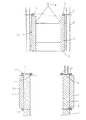
In the construction phase illustrated in FIG. 1, the peripherally closed construction to be equipped is partially finished. In the concrete stroke, a plurality of peripherally closed portions of the concrete wall have already been manufactured, and one
[0012]
The
[0013]
From the concrete stroke, a
[0014]
Instead of the cone 9, other equipment for centering the
[0015]
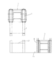
The
[0016]
As the next step, the space between the inner shell and the
[0017]
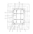
In order to remove the
[0018]
In order to remove the inner shell unit, the
[0019]
In order to remove the inner shell unit, it could be divided in the peripheral direction in other ways.
[0020]
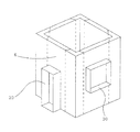
FIG. 6 further shows the
[0021]
Instead of the square contour shown, the structure to be built has another peripheral closed contour, for example a rectangular polygon or a circular contour.
[0022]
The
[Brief description of the drawings]
FIG. 1 shows a schematic longitudinal section through a construct produced by the method of the invention in one constituent phase.
FIG. 2 shows a schematic longitudinal section through the construct produced by the method of the invention in another constituent phase.
FIG. 3 shows a schematic longitudinal section through the construct produced by the method of the invention in yet another constituent phase.
4 shows a schematic plan view of the construct in the constituent phase according to FIG.
FIG. 5 shows a schematic perspective view of the intermediate segment with the inner shell unit removed.
FIG. 6 shows a schematic perspective representation of an internal shell unit comprising a shell member that opens an opening in a concrete wall.
[Explanation of symbols]
1. . . . .
4). . . . . Hoist 5. . . . . Internal shell unit6. . . . .
Claims (6)
Applications Claiming Priority (2)
| Application Number | Priority Date | Filing Date | Title |
|---|---|---|---|
| AT0176901A AT411079B (en) | 2001-11-09 | 2001-11-09 | METHOD FOR THE CONSTRUCTION OF A CONSTRUCTION WITH A CONCRETE WALL CONTAINED IN A CIRCUMFERENCE |
| AT1769/2001 | 2001-11-09 |
Publications (2)
| Publication Number | Publication Date |
|---|---|
| JP2003184304A JP2003184304A (en) | 2003-07-03 |
| JP4074804B2 true JP4074804B2 (en) | 2008-04-16 |
Family
ID=3688878
Family Applications (1)
| Application Number | Title | Priority Date | Filing Date |
|---|---|---|---|
| JP2002319639A Expired - Fee Related JP4074804B2 (en) | 2001-11-09 | 2002-11-01 | Method for constructing a structure with a peripheral closed concrete wall |
Country Status (5)
| Country | Link |
|---|---|
| US (1) | US6921501B2 (en) |
| EP (1) | EP1338724B1 (en) |
| JP (1) | JP4074804B2 (en) |
| AT (2) | AT411079B (en) |
| DE (1) | DE50212317D1 (en) |
Families Citing this family (6)
| Publication number | Priority date | Publication date | Assignee | Title |
|---|---|---|---|---|
| WO2007025555A1 (en) * | 2005-08-30 | 2007-03-08 | Icec Holding Ag | Method for vertically extruding a concrete element, device for producing a concrete element and devices produced by this method |
| US9768603B2 (en) * | 2009-08-24 | 2017-09-19 | Siemens Aktiengesellschaft | Lightning protection system |
| BR112017008829A2 (en) * | 2014-10-31 | 2017-12-19 | Soletanche Freyssinet | concrete building block fabrication process for a wind turbine tower and associated system |
| CN104594633B (en) * | 2015-01-20 | 2017-03-29 | 中国建筑第八工程局有限公司 | The construction method and its formwork structure of umbrella shape space curved surface clear-water concrete |
| DE102018203262A1 (en) * | 2018-03-06 | 2019-09-12 | Peri Gmbh | Shuttering device and method for producing vertical wall sections with connection reinforcement elements for a floor slab |
| CN112727069B (en) * | 2020-12-23 | 2022-08-26 | 新疆杰建建设工程有限公司 | A built-up plate for construction of foundation engineering wall concrete |
Family Cites Families (16)
| Publication number | Priority date | Publication date | Assignee | Title |
|---|---|---|---|---|
| US836667A (en) * | 1906-06-11 | 1906-11-27 | Alvin C Burns | Concrete-wall mold. |
| US1478653A (en) * | 1923-03-30 | 1923-12-25 | Holmes Arthur Edward | Concrete-wall boxing |
| US3224065A (en) * | 1965-04-22 | 1965-12-21 | David B Cheskin | Apparatus for building a hollow core structure |
| US3583666A (en) * | 1967-12-12 | 1971-06-08 | S O G Research And Dev Corp | Concrete forms with replaceable inserts |
| US3588026A (en) * | 1968-05-27 | 1971-06-28 | Chester I Williams | Two-stage form-securing system |
| US4043087A (en) * | 1975-12-08 | 1977-08-23 | Symons Corporation | Method and means for supporting an elevated concrete wall panel form |
| IT1071572B (en) * | 1977-02-10 | 1985-04-10 | Tesco Spa | SELF-ASSEMBLING FORMWORK FOR THE CAST OF CONCRETE STRUCTURES AND LAND SUPPORTING WALLS |
| US4300746A (en) * | 1977-09-14 | 1981-11-17 | Schoen Investments, Inc. | Apparatus and method for manufacturing concrete structural modules |
| DE2948255A1 (en) * | 1979-11-30 | 1981-06-04 | Philipp Holzmann Ag, 6000 Frankfurt | METHOD FOR PROTECTING THE SURFACES OF CONCRETE CONSTRUCTIONS, AND SEALING ELEMENT FOR CARRYING OUT THIS METHOD |
| US4422617A (en) * | 1982-01-15 | 1983-12-27 | Harsco Corporation | Edge joist |
| US4709899A (en) * | 1985-10-28 | 1987-12-01 | Shimizu Construction Co., Ltd. | Climbing formwork apparatus for concrete placing |
| US4974700A (en) * | 1989-06-12 | 1990-12-04 | Gates & Sons, Inc. | Movable support mechanism for construction of elevator shafts and the like |
| US5088578A (en) * | 1989-06-12 | 1992-02-18 | Gates & Sons, Inc. | Movable support mechanism for construction of elevator shafts and the like |
| JP2913436B2 (en) * | 1992-03-31 | 1999-06-28 | 株式会社間組 | Mobile formwork method and equipment used for the method |
| DE19639038C1 (en) * | 1996-09-23 | 1998-06-04 | Doka Ind Gmbh | Climbing formwork system and method for successive concreting of high vertical walls |
| DE29911524U1 (en) * | 1999-07-06 | 2001-01-04 | Heinzle Otto | Scaffolding for the construction of round towers made of reinforced concrete |
-
2001
- 2001-11-09 AT AT0176901A patent/AT411079B/en active
-
2002
- 2002-10-11 EP EP02022744A patent/EP1338724B1/en not_active Expired - Lifetime
- 2002-10-11 AT AT02022744T patent/ATE397132T1/en active
- 2002-10-11 DE DE50212317T patent/DE50212317D1/en not_active Expired - Lifetime
- 2002-11-01 JP JP2002319639A patent/JP4074804B2/en not_active Expired - Fee Related
- 2002-11-06 US US10/288,872 patent/US6921501B2/en not_active Expired - Fee Related
Also Published As
| Publication number | Publication date |
|---|---|
| EP1338724A3 (en) | 2007-09-26 |
| EP1338724B1 (en) | 2008-05-28 |
| AT411079B (en) | 2003-09-25 |
| ATA17692001A (en) | 2003-02-15 |
| DE50212317D1 (en) | 2008-07-10 |
| US20030089074A1 (en) | 2003-05-15 |
| US6921501B2 (en) | 2005-07-26 |
| EP1338724A2 (en) | 2003-08-27 |
| JP2003184304A (en) | 2003-07-03 |
| ATE397132T1 (en) | 2008-06-15 |
Similar Documents
| Publication | Publication Date | Title |
|---|---|---|
| KR101903628B1 (en) | Precast Double Wall Structure with Enhanced Seismic Performance and Construction method thereof | |
| CA2454069C (en) | Structure of pile head joint portion and pile head fitting tubular body | |
| KR20200002390A (en) | Double-Wall Precast Pannel Manufacturing Method Using Tilting Concrete Form | |
| JP4074804B2 (en) | Method for constructing a structure with a peripheral closed concrete wall | |
| CN114150766A (en) | Prefabricated reinforced concrete column connecting joint and construction method thereof | |
| CN110056358A (en) | A kind of template and support system and construction method for the construction of vertical shaft inwall | |
| JP2001254516A (en) | Erection method of src steel column in which pc concrete is poured on ground | |
| KR102196145B1 (en) | Process for field constructing pier structure with precast segment | |
| JP3044459B2 (en) | Tower structure construction method | |
| JPH1018424A (en) | Root wrapping reinforcing structure of column base of steel post or the like | |
| JPH0657956A (en) | Construction of concrete structure | |
| JP2889840B2 (en) | Construction method of underground outer peripheral wall | |
| CN211775105U (en) | Prefabricated column and beam column connecting structure comprising same | |
| JPH0742721B2 (en) | Reinforced concrete column / beam construction method using precast beam members | |
| JPH0734534A (en) | Prefabricated structure for reinforced concrete-made offset beam | |
| CN109057159A (en) | Prefabricated laminated superposed column, assembled architecture body and assembled architecture body method of construction | |
| JP6261333B2 (en) | Seismic reinforcement method | |
| JPH11247450A (en) | Precast column unit and column construction method using it | |
| JP2600531B2 (en) | Foundation structure for steel column and its construction method | |
| JPH073726A (en) | Bridge pier construction execution | |
| JPH0765339B2 (en) | Concrete pillar construction method | |
| JPH0684686B2 (en) | Standing method for precast concrete columns | |
| KR20220112000A (en) | Descent apparatus downward construction system method using thereof | |
| SU1458502A1 (en) | Arrangement for constructing a foundation | |
| JP2738276B2 (en) | Sliding formwork device |
Legal Events
| Date | Code | Title | Description |
|---|---|---|---|
| A621 | Written request for application examination |
Free format text: JAPANESE INTERMEDIATE CODE: A621 Effective date: 20050720 |
|
| TRDD | Decision of grant or rejection written | ||
| A01 | Written decision to grant a patent or to grant a registration (utility model) |
Free format text: JAPANESE INTERMEDIATE CODE: A01 Effective date: 20080108 |
|
| A61 | First payment of annual fees (during grant procedure) |
Free format text: JAPANESE INTERMEDIATE CODE: A61 Effective date: 20080128 |
|
| FPAY | Renewal fee payment (event date is renewal date of database) |
Free format text: PAYMENT UNTIL: 20110201 Year of fee payment: 3 |
|
| R150 | Certificate of patent or registration of utility model |
Free format text: JAPANESE INTERMEDIATE CODE: R150 |
|
| FPAY | Renewal fee payment (event date is renewal date of database) |
Free format text: PAYMENT UNTIL: 20120201 Year of fee payment: 4 |
|
| FPAY | Renewal fee payment (event date is renewal date of database) |
Free format text: PAYMENT UNTIL: 20130201 Year of fee payment: 5 |
|
| R250 | Receipt of annual fees |
Free format text: JAPANESE INTERMEDIATE CODE: R250 |
|
| S111 | Request for change of ownership or part of ownership |
Free format text: JAPANESE INTERMEDIATE CODE: R313113 |
|
| R350 | Written notification of registration of transfer |
Free format text: JAPANESE INTERMEDIATE CODE: R350 |
|
| R250 | Receipt of annual fees |
Free format text: JAPANESE INTERMEDIATE CODE: R250 |
|
| LAPS | Cancellation because of no payment of annual fees |