DE102018203262A1 - Shuttering device and method for producing vertical wall sections with connection reinforcement elements for a floor slab - Google Patents
Shuttering device and method for producing vertical wall sections with connection reinforcement elements for a floor slab Download PDFInfo
- Publication number
- DE102018203262A1 DE102018203262A1 DE102018203262.9A DE102018203262A DE102018203262A1 DE 102018203262 A1 DE102018203262 A1 DE 102018203262A1 DE 102018203262 A DE102018203262 A DE 102018203262A DE 102018203262 A1 DE102018203262 A1 DE 102018203262A1
- Authority
- DE
- Germany
- Prior art keywords
- formwork
- shuttering
- reinforcement elements
- edge recesses
- connection reinforcement
- Prior art date
- Legal status (The legal status is an assumption and is not a legal conclusion. Google has not performed a legal analysis and makes no representation as to the accuracy of the status listed.)
- Withdrawn
Links
Images


Classifications
-
- E—FIXED CONSTRUCTIONS
- E04—BUILDING
- E04G—SCAFFOLDING; FORMS; SHUTTERING; BUILDING IMPLEMENTS OR AIDS, OR THEIR USE; HANDLING BUILDING MATERIALS ON THE SITE; REPAIRING, BREAKING-UP OR OTHER WORK ON EXISTING BUILDINGS
- E04G11/00—Forms, shutterings, or falsework for making walls, floors, ceilings, or roofs
- E04G11/06—Forms, shutterings, or falsework for making walls, floors, ceilings, or roofs for walls, e.g. curved end panels for wall shutterings; filler elements for wall shutterings; shutterings for vertical ducts
- E04G11/20—Movable forms; Movable forms for moulding cylindrical, conical or hyperbolical structures; Templates serving as forms for positioning blocks or the like
- E04G11/28—Climbing forms, i.e. forms which are not in contact with the poured concrete during lifting from layer to layer and which are anchored in the hardened concrete
-
- E—FIXED CONSTRUCTIONS
- E04—BUILDING
- E04G—SCAFFOLDING; FORMS; SHUTTERING; BUILDING IMPLEMENTS OR AIDS, OR THEIR USE; HANDLING BUILDING MATERIALS ON THE SITE; REPAIRING, BREAKING-UP OR OTHER WORK ON EXISTING BUILDINGS
- E04G17/00—Connecting or other auxiliary members for forms, falsework structures, or shutterings
- E04G17/007—Plugs to close openings in forms' surface
-
- E—FIXED CONSTRUCTIONS
- E04—BUILDING
- E04G—SCAFFOLDING; FORMS; SHUTTERING; BUILDING IMPLEMENTS OR AIDS, OR THEIR USE; HANDLING BUILDING MATERIALS ON THE SITE; REPAIRING, BREAKING-UP OR OTHER WORK ON EXISTING BUILDINGS
- E04G17/00—Connecting or other auxiliary members for forms, falsework structures, or shutterings
- E04G17/02—Connecting or fastening means for non-metallic forming or stiffening elements
Abstract
Die Erfindung betrifft eine Schalvorrichtung zum Erzeugen eines Wandabschnitts (60) mit auskragenden Anschlussbewehrungselementen (52) in Frischbetonbauweise für den Anschluss einer zu erstellenden Geschossdecke, umfassend ein Schalungselement (10) mit einer Stutzstruktur (14) und mit einer an der Stützstruktur (14) abgestützten Schaltafel (12). Das Schalungselement (10) ist erfindungsgemäß an einem seiner Randabschnitte (30) mit einer Vielzahl von, bevorzugt regelmäßig, voneinander beabstandet angeordneten Randaussparungen (32) für die Anschlussbewehrungselemente (52) versehen. Zum reversiblen Abdecken der Randaussparungen (32) bei sich durch die Randaussparungen (32) hindurcherstreckenden Anschlussbewehrungselementen (32) dient ein einzelnes Schalplattenelement (36) oder mehrere Schalplattenelemente (36). Die Erfindung betrifft darüber hinaus ein Verfahren zum Erzeugen von in Lotrichtung übereinanderliegend angeordneten Wandabschnitten (60) mit auskragenden Anschlussbewehrungselementen (52) in Frischbetonweise für den Anschluss einer Geschossdecke.The invention relates to a scarfing device for producing a wall section (60) with projecting connecting reinforcement elements (52) in fresh concrete construction for connecting a floor slab to be created, comprising a formwork element (10) with a support structure (14) and with a supported on the support structure (14) Chalkboard (12). The shuttering element (10) according to the invention at one of its edge portions (30) with a plurality of, preferably regularly, spaced from each other arranged edge recesses (32) for the connection reinforcement elements (52). For reversibly covering the edge recesses (32) with connecting reinforcement elements (32) extending through the edge recesses (32), a single shuttering plate element (36) or several shuttering plate elements (36) is used. The invention furthermore relates to a method for producing wall sections (60) arranged one above the other in the vertical direction with projecting connecting reinforcement elements (52) in a fresh concrete manner for the connection of a floor slab.
Description
Im Betonbau werden vertikale Wandabschnitte für den Anschluss von Geschossdecken und dergleichen in der Regel mit einer sogenannten Anschlussbewehrung versehen, deren einzelne Anschlussbewehrungselemente aus dem Wandabschnitt herausstehen. Am Markt sind sogenannte Rückbiegeanschlüsse verfügbar, bei denen eine glatte, exakt ausgerichtete Arbeitsfuge mit der Schalung erstellt werden kann, ohne dass diese dafür durchbohrt werden muss. Im Gegensatz zu den sogenannten Schraubanschlüssen zeichnen sich diese zudem durch geringere Anschaffungs- und Einbaukosten aus. In concrete vertical wall sections for the connection of floor slabs and the like are usually provided with a so-called connection reinforcement, the individual connection reinforcement elements protrude from the wall section. So-called rebend connections are available on the market where a smooth, precisely aligned construction joint can be created with the formwork without having to pierce it. In contrast to the so-called screw connections, these are also characterized by lower acquisition and installation costs.
Begrenzt werden Rückbiegeanschlüsse allerdings durch den maximalen Stabdurchmesser. Üblicherweise sind nur Anschlüsse mit einem Durchmesser des Bewehrungsstahls bis einschließlich 12 Millimeter möglich, sodass verschärfte Brandschutzanforderungen nicht ohne Weiteres erfüllt werden können. In der Praxis werden deshalb zumeist Anschlussbewehrungselemente aus formgebogenem Bewehrungsstahl eingesetzt. Diese sind häufig L- förmig oder U-förmig ausgeführt und werden zumindest abschnittsweise in dem jeweiligen in Frischbetonbauweise herzustellenden Beton-Wandabschnitt eingegossen.However, bending-back connections are limited by the maximum bar diameter. Usually, only connections with a diameter of the rebar up to and including 12 millimeters are possible, so that more stringent fire safety requirements can not be met easily. In practice, connection reinforcement elements made of formed reinforcing steel are therefore usually used in practice. These are often L-shaped or U-shaped and are at least partially cast in the concrete concrete wall section to be produced in fresh concrete construction.
Beim Bau eines mehrgeschossigen Betonbaus werden aus Zeit- und Kostengründen bekanntlich häufig Gleit- oder Kletterschalungen eingesetzt. Die vorgenannten Anschlussbewehrungselemente stellen hier eine erhebliche Störgröße dar. So müssen die Schalungselemente in der Praxis nach dem Ausschalen des verfestigten Wandabschnitts in der Regel aufwändig um die Anschlussbewehrungselemente herum zu dem nächsthöhergelegenen Bauabschnitt bewegt werden. Dies ist zeit-, personal- und kostenaufwändig.When building a multi-storey concrete construction, sliding or climbing formwork is often used for reasons of time and cost. The abovementioned connecting reinforcement elements here represent a considerable interference variable. In practice, after the stripping of the solidified wall section, the formwork elements generally have to be moved around the connecting reinforcement elements in a complex manner to the next higher construction section. This is time, personnel and costly.
Aufgabe der Erfindung ist es deshalb, eine Schalungsvorrichtung und ein Verfahren anzugeben, mit denen sich vertikale Wandabschnitte in Frischbetonbauweise mit jeweils auskragenden Anschlussbewehrungselementen einfacher und kostengünstiger erzeugen lassen.The object of the invention is therefore to provide a formwork device and a method with which vertical wall sections in fresh concrete construction with each projecting connection reinforcement elements can be generated easier and cheaper.
Die die Schalungsvorrichtung betreffende Aufgabe wird durch eine Schalungsvorrichtung mit den in Anspruch 1 angegebenen Merkmalen gelöst. Das erfindungsgemäße Verfahren weist die in Anspruch 10 angegebenen Merkmale auf. Bevorzugte Weiterbildungen der Erfindung sind in den Unteransprüchen sowie in der Beschreibung angegeben.The object relating to the formwork device is achieved by a formwork device having the features specified in
Die erfindungsgemäße Schalungsvorrichtung weist ein Schalungselement mit einer Stützstruktur und eine an der Stützstruktur abgestützte Schaltafel mit einer Schalhaut auf. Die Schalhaut ist diejenige Oberfläche der Schaltafel, die mit dem Frischbeton in Kontakt kommt, welcher zum Betonieren des zu erstellenden Wandabschnitts eingesetzt wird. Die Stützstruktur kann mehrere Schalungsträger, beispielweise in Fachwerkbauweise, umfassen, die untereinander lösbar verbunden sind. Erfindungsgemäß weist das Schalungselement an seinem unteren Randabschnitt eine Vielzahl von, bevorzugt regelmäßig, voneinander beabstandet angeordneten Randaussparungen zum Durchführen der Anschlussbewehrungselemente des zu erstellenden Wandabschnitts auf. Das Schalungselement weist somit entlang seines unteren Randabschnitts voneinander beabstandete Einbuchtungen auf, die der Aufnahme der vorgenannten Anschlussbewehrungselemente, insbesondere Bewehrungsstäbe aus Stahl, dienen. Dadurch kann das Schalungselement beim Einschalen des in Frischbetonbauweise zu erstellenden Wandabschnitts auf einfache Weise in seiner für den jeweilig zu erstellenden Wandabschnitt vorgegebenen Einschalposition angeordnet werden. Sind die Anschlussbewehrungselemente, beispielsweise in Form von L-förmig gebogenen Bewehrungsstäben, bereits einenends in einem darunterliegend angeordneten Betonbaukörper bzw. Wandabschnitt verankert, so kann das Schalungselement auf diese Anschlussbewehrungselemente in Lotrichtung und/oder in einer zum Wandabschnitt orthogonalen Richtung aufgeschoben werden. Die Schalvorrichtung weist zum reversiblen Abdecken der Randaussparungen bei sich durch die Randaussparungen hindurcherstreckenden Anschlussbewehrungselementen erfindungsgemäß ein Schalplattenelement oder mehrere Schalplattenelemente auf. Dadurch kann einem unerwünschten Austreten des Frischbetons beim Betonieren des Wandabschnitts über die Randaussparungen entgegengewirkt werden. Jedes Schalplattenelement dient somit als ein Dichtungselement. Ist das Schalplattenelement beispielsweise in Form eines einzelnen Schalbretts ausgebildet, so weist dieses für die Anschlussbewehrungselemente des zu erstellenden Wandabschnitts eine Vielzahl von Durchgangsausnehmungen auf. Das einzelne Schalbrett weist dabei bevorzugt eine zur Breite des Schalungselements korrespondierende Länge auf. Dies bietet beim Einschalen des zu erstellenden Wandabschnitts Zeit- und Kostenvorteile. Im Falle der mehreren Schalplattenelemente ist jedes der Schalplattenelemente mit jeweils zumindest einer Durchgangsausnehmung, bevorzugt mit mehreren Durchgangsausnehmungen, versehen.The shuttering device according to the invention has a shuttering element with a support structure and a shuttering plate supported on the support structure with a shuttering skin. The formwork skin is that surface of the formwork panel that comes in contact with the fresh concrete used for concreting the wall section to be created. The support structure may comprise a plurality of formwork beams, for example in timber-frame construction, which are detachably connected to one another. According to the invention, the formwork element at its lower edge portion on a plurality of, preferably regularly, spaced-apart edge recesses for performing the connection reinforcement elements of the wall section to be created. The shuttering element thus has along its lower edge portion spaced notches, which serve to receive the aforementioned connection reinforcement elements, in particular reinforcing bars made of steel. As a result, the shuttering element can be arranged in a simple manner in its intended for the respective wall section to be created Einschalposition when enclosing the fresh concrete construction to be created wall section. If the connecting reinforcement elements, for example in the form of reinforcing bars bent in an L-shape, are already anchored at one end in a concrete structural element or wall section arranged underneath, the shuttering element can be pushed onto these connecting reinforcement elements in the vertical direction and / or in a direction orthogonal to the wall section. The scarf device according to the invention has a formwork panel element or a plurality of formwork panel elements for reversibly covering the edge recesses in the case of connecting reinforcement elements extending through the edge recesses. This can be counteracted undesirable leakage of the fresh concrete during concreting of the wall section over the edge recesses. Each formwork element thus serves as a sealing element. If the formwork panel element is designed, for example, in the form of a single formwork board, then this has a multiplicity of throughholes for the connection reinforcement elements of the wall section to be created. The individual formwork board preferably has a length corresponding to the width of the formwork element. This offers time and cost advantages when enclosing the wall section to be created. In the case of a plurality of shuttering plate elements, each of the shuttering plate elements is provided with in each case at least one passage recess, preferably with a plurality of passage openings.
Nach einer besonders bevorzugten Ausführungsform der Erfindung ist jedes Schalplattenelement in einer zur Längsachse des Schalungselements axialen Richtung aus seiner Montageposition am Schalungselement herausbewegbar. Dadurch kann das Schalungselement vereinfacht ausgeschalt und von den Anschlussbewehrungselementen des verfestigten Wandabschnitts in Lotrichtung nach oben bewegt werden. Ein Wegbewegen des Schalungselements vom Wandabschnitt in einer zur Wandoberfläche des verfestigten Wandabschnitts orthogonalen Richtung bis zum freien Ende der Anschlussbewehrungselemente erübrigt sich. Dadurch kann auch auf engstem Bauraum ausgeschalt und das Schalungselement zum nächsthöheren Bauabschnitt bewegt werden. Zu beachten ist, dass das einzelne Schalplattenelement bzw. die mehreren Schalplattenelemente separat von den Anschlussbewehrungselementen des verfestigten Wandabschnitts in einer zur Wandoberfläche des Wandabschnitts orthogonalen Richtung abgezogen werden können.According to a particularly preferred embodiment of the invention, each formwork panel element can be moved out of its mounting position on the formwork element in an axial direction to the longitudinal axis of the formwork element. As a result, the shuttering element can be switched off and simplified by the Connection reinforcement elements of the solidified wall portion are moved in the vertical direction upwards. Moving away the formwork element from the wall portion in a direction orthogonal to the wall surface of the solidified wall portion to the free end of the connecting reinforcement elements is unnecessary. As a result, it can be switched off even in the most confined space and the formwork element can be moved to the next higher construction section. It should be noted that the individual shell plate element or the plurality of shell plate elements can be removed separately from the connection reinforcement elements of the solidified wall portion in a direction orthogonal to the wall surface of the wall portion.
Besonders bevorzugt ist jedes der mehreren Schalplattenelemente zumindest abschnittsweise in einer der Randaussparungen anordenbar. Dadurch kann eine besonders zuverlässige Abdichtung der Randaussparungen erreicht werden. Darüber hinaus kann einem unerwünschten Fehlpositionieren der Schalplattenelemente relativ zum Schalungselement entgegengewirkt und diese bei Bedarf verliersicher am Schalungselement gehalten werden.Particularly preferably, each of the plurality of shuttering plate elements can be arranged at least in sections in one of the edge recesses. This allows a particularly reliable sealing of the edge recesses can be achieved. In addition, an undesired incorrect positioning of the formwork panel elements can be counteracted relative to the formwork element and these are held captive on formwork element if necessary.
Nach der Erfindung kann jedes Schalplattenelement über eine Spundung mit dem Schalungselement, insbesondere mit dessen Schaltafel, lösbar verbindbar sein. Durch die Spundung kann eine nochmals bessere Abdichtung der Randaussparungen erreicht werden. Darüber hinaus kann dadurch ein verliersicherer Sitz des Schalplattenelements bzw. der Schalplattenelemente am Schalungselement gewährleistet werden.According to the invention, each formwork panel element via a bung with the formwork element, in particular with its formwork panel, be releasably connectable. By bouncing even better sealing of the edge recesses can be achieved. In addition, this can ensure a captive seat of the shuttering plate element or the formwork element elements on the formwork element.
Nach einer bevorzugten Weiterbildung erstreckt sich die Schaltafel des Schalungselements zwischen zwei unmittelbar benachbart angeordneten Randaussparungen. Die Schaltafel ist vorzugsweise auch in diesen Bereichen durch die Stützstruktur rückseitig abgestützt. Die Schaltafel kann sich dabei bis zum freien Rand des Schalungselements erstrecken.According to a preferred embodiment, the formwork panel of the formwork element extends between two immediately adjacent arranged edge recesses. The formwork panel is preferably also supported in these areas by the support structure on the back. The formwork panel can extend to the free edge of the formwork element.
Das Schalungselement kann insbesondere als ein sogenanntes Rahmentafelschalungselement ausgebildet sein, bei dem die Schalhaut und die Stützstruktur dauerhaft miteinander verbunden sind. Die Stützstruktur ist hier in der Regel durch Hohlprofilelemente aus Metall gebildet, die miteinander unlösbar verbunden, insbesondere miteinander verschweißt, sind. Die Hohlprofilelemente können die Schaltafel zumindest abschnittsweise randseitig schützend übergreifen.The formwork element may in particular be designed as a so-called frame panel formwork element, in which the formwork skin and the support structure are permanently connected to one another. The support structure is here usually formed by hollow profile elements made of metal, which are inseparably connected to each other, in particular welded together, are. The hollow profile elements can overlap the panel at least partially protective edge.
Verjüngen sich die Randaussparungen des Schalungselements in ihrer Breite zur Mitte bzw. zum gegenüberliegenden oberen Rand des Schalungselements hin, so können die einzelnen Schalplatteneinsätze besonders zuverlässig dichtend in die Randaussparungen des Schalungselements eingeschoben werden.If the edge recesses of the formwork element taper in their width toward the center or towards the opposite upper edge of the formwork element, then the individual formwork insert elements can be pushed into the edge recesses of the formwork element in a particularly reliable manner.
Das Schalplattenelement/die Schalplattenelemente können in ihrer Montageposition mit ihrer mit dem Frischbeton in Kontakt kommenden Schalhaut (Schalfläche) über das Niveau der Schalhaut des Schalungselements hervorstehen. Die Schalplattenelemente zeichnen sich dadurch im verfestigten Wandabschnitt jeweils als eine Vertiefung ab. Jede Vertiefung umgreift dabei jeweils zumindest ein aus dem Wandabschnitt herausragendes Anschlussbewehrungselement. Dadurch kann ggf. eine nochmals laststabilere Anbindung der jeweiligen Geschossdecke am Wandabschnitt erreicht werden.The Schalplattenelement / the Schalplattenelemente may protrude in their mounting position with their coming into contact with the fresh concrete formwork (Schalfläche) on the level of the formwork skin of the formwork element. The formwork panel elements are characterized in the solidified wall section each as a recess. Each depression engages in each case at least one connecting reinforcement element protruding from the wall section. As a result, it is possible, if necessary, to achieve a more load-stable connection of the respective floor slab to the wall section.
Ist die Schalhaut des Schalplattenelements bzw. der Schalplattenelemente in seinem/ihrem Montagezustand am Schalungselement zur Schalhaut des Schalungselements jeweils bündig oder im Wesentlichen bündig angeordnet, so kann der Wandabschnitt mit einer stufenfreien oder im Wesentlichen stufenfreien Oberfläche erzeugt werden.If the formlining of the formwork panel element or of the formwork panel elements is in each case flush or substantially flush in its / their mounting state on the formwork element for formwork skin of the formwork element, the wall section can be produced with a step-free or substantially step-free surface.
Das erfindungsgemäße Verfahren zum Erzeugen von in Lotrichtung übereinanderliegend angeordneten Wandabschnitten in Frischbetonweise, die jeweils mit auskragenden Anschlussbewehrungselementen für den Anschluss einer zu erstellenden Geschossdecke versehen sind, umfasst die folgenden Schritte:
- a) Einschalen eines ersten zu erstellenden Wandabschnitts mit einer Betonschalung, die zumindest eine vorstehend erläuterte Schalungsvorrichtung umfasst, derart, dass sich zumindest ein Teil der Anschlussbewehrungselemente des zu erstellenden Wandabschnitts durch jeweils eine der Randaussparungen des Schalungselements hindurcherstreckt, wobei die von den Anschlussbewehrungselementen durchgriffenen Randaussparungen des Schalungselements entweder zu mehreren, bevorzugt alle gemeinsam, durch ein einzelnes Schalplattenelement, insbesondere in Form eines Schalbretts, oder jeweils - unabhängig voneinander - durch ein separates Schalplattenelement abgedeckt sind, das zumindest abschnittsweise in der jeweiligen Randaussparung angeordnet ist.
- b) Einbringen von Frischbeton in die Betonschalung;
- c) Ausschalen des verfestigten Wandabschnitts durch
- - Anheben des Schalungselements in Lotrichtung, um die Anschlussbewehrungselemente außer Eingriff mit dem Schalungselement zu bringen; und
- - Abziehen eines jeden Schalplattenelements von dem/den jeweiligen Anschlussbewehrungselement(en) in einer zum Wandabschnitt orthogonalen Richtung; und
- d) Einschalen eines sich in Lotrichtung oberhalb des verfestigten Wandabschnitts anschließenden zweiten zu erstellenden Wandabschnitts mit auskragenden Anschlussbewehrungselementen für den Anschluss einer Geschossdecke mit der Schalungsvorrichtung.
- a) enclosing a first wall section to be created with a concrete formwork, which comprises at least one formwork device explained above, such that at least a part of the connection reinforcement elements of the wall section to be created extends through in each case one of the edge recesses of the formwork element, wherein the edge recesses of the wall element are traversed by the connection reinforcement elements Shuttering element either to several, preferably all together, are covered by a single formwork panel element, in particular in the form of a formwork board, or each - independently - are covered by a separate formwork element, which is at least partially disposed in the respective edge recess.
- b) introducing fresh concrete into the concrete formwork;
- c) stripping the solidified wall section through
- - Lifting the shuttering element in the direction of solder, to bring the connection reinforcement elements out of engagement with the shuttering element; and
- - Withdrawing each formwork panel element from the respective connection reinforcement element (s) in a direction orthogonal to the wall section; and
- d) shaving in a subsequent in the vertical direction above the solidified wall portion second wall section to be created with cantilever connecting reinforcement elements for the connection of a floor slab with the formwork device.
Besonders bevorzugt wird beim Einschalen des jeweiligen Wandabschnitts zuerst das einzelne Schalplattenelement oder werden die Schalplattenelemente auf das/die Anschlussbewehrungselemente aufgefädelt und erst danach das Schalungselement in Einschalposition überführt.When sheathing the respective wall section, it is particularly preferred to first of all thread the individual shuttering panel element or the shuttering panel elements onto the connecting reinforcing element (s) and only then transfer the shuttering element into the shuttering position.
Nachfolgend wird die Erfindung anhand von in der Zeichnung dargestellten Ausführungsbeispielen näher erläutert. Die gezeigten und beschriebenen Ausführungsformen sind nicht als abschließende Aufzählung zu verstehen, sondern haben vielmehr beispielhaften Charakter für die Schilderung der Erfindung.The invention will be explained in more detail with reference to embodiments shown in the drawing. The embodiments shown and described are not to be understood as exhaustive enumeration, but rather have exemplary character for the description of the invention.
In der Zeichnung zeigen:
-
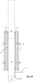
1 ein Schalungselement mit einer Schaltafel, die rückseitig an einer Stützstruktur abgestützt ist, wobei das Schalungselement entlang seines unteren Randabschnitts mehrere Randaussparungen für Anschlussbewehrungselemente eines zu erstellenden Wandabschnitts aufweist, in einer Ansicht auf die Rückseite; -
2 ein Schalplattenelement mit zwei Ausnehmungen für ein Anschlussbewehrungselement und mit einer umfangsseitig angeordneten Haltenut, in einer Vorderansicht (2A) , einer perspektivischen Ansicht (2B) , einer Seitenansicht (2C ) und einer stirnseitigen Ansicht (2D ); -
3 ein weiteres Schalplattenelement mit insgesamt vier Ausnehmungen für das Durchführen von Anschlussbewehrungselementen und mit einer umfangsseitig angeordneten Haltenut, in einer Vorderansicht (3A) , einer perspektivischen Ansicht (3B) , einer Seitenanicht (3C ) und einer stirnseitigen Ansicht (3D ); -
4 eine Betonschalung mit einander gegenüberliegend angeordneten Schalungselementen zum Erzeugen eines Wandabschnitts mit auskragenden Anschlussbewehrungselementen in Frischbetonbauweise, wobei das in der Fig. rechte Schalungselement gemäß1 ausgeführt ist und sich die Anschlussbewehrungselemente jeweils durch ein in den Randaussparungen des Schalungselements angeordnetes Schalplattenelement hindurcherstrecken, in einer Seitenansicht; -
5 die Betonschalung gemäß4 in einer ausschnittsweisen Schnittdarstellung; -
6 die Betonschalung gemäß4 in einem ausschnittsweisen Horizontalschnitt; -
7 die Betonschalung gemäß4 in einem perspektivischen Detailausschnitt; -
8 eine Betonschalung, bei der sich jeweils zwei Anschlussarmierungselemente durch dasselbe Schalplattenelement hindurcherstrecken, in einem ausschnittsweisen Horizontalschnitt; -
9 ein Schalungsbild eines ausgeschalten verfestigten Wandabschnitts mit Anschlussbewehrungselementen, in einer perspektivischen Ansicht; -
10 ein alternatives Schalplattenelement mit insgesamt zwei Ausnehmungen für das Durchführen von Anschlussbewehrungselementen in einer Vorderansicht (10A) , und in einer perspektivischen Ansicht (10B) ; -
11 ein alternatives Schalplattenelement mit insgesamt vier Ausnehmungen für das Durchführen von Anschlussbewehrungselementen in einer Vorderansicht (11A) und in einer perspektivischen Ansicht (11B) ; -
12 eine ausschnittsweise Detaildarstellung einer Betonschalung mit einem Schalplattenelement gemäß10 oder 11 , in einer Schnittdarstellung; -
13 ein einzelnes Schalungsbrett zum Abdecken der Randaussparungen eines Schalungselements gemäß1 , in einer perspektivischen Ansicht; -
14 eine Betonschalung, bei dem indas der 14 rechts dargestellte Schalungselement gemäß1 ausgeführt ist und sich alle Anschlussbewehrungselemente des zu erstellenden Wandabschnitts gemeinsam durch ein an der Schalhaut anliegendes Schalungsbrett gemäß13 hindurcherstrecken, in einer Schnittdarstellung; -
15 das Schalungsbild des mit der Betonschalung gemäß14 erzeugten verfestigten Wandabschnitts, in einer perspektivischen Ansicht; -
16 eine weitere Ausführungsform eines Schalungselements; -
17 eine Betonschalung mit einem Schalungselement gemäß16 , bei dem die Randaussparungen gemeinsam durch ein einziges Schalbrett abgedeckt sind, das rückseitig an der Stützstruktur des Schalungselements unmittelbar anliegt, in einer perspektivischen Darstellung; -
18 das Schalungsbild eines mit der Betonschalung gemäß17 erzeugten Wandabschnitts, in einer perspektivischen Ansicht; -
19 eine Betonschalung beim Ausschalen, in einer Seitenansicht; -
20 ein Blockdiagramm mit einzelnen Verfahrensschritten zum Erzeugen eines Wandabschnitts in Frischbetonweise, der mit im Beton eingebetteten und Anschlussbewehrungselementen für den Anschluss einer in zu erstellenden Geschossdecke versehen ist, wobei sich die Anschlussbewehrungselemente jeweils in einer zur Oberfläche des Wandabschnitts orthogonalen Richtung vom Wandabschnitt wegerstrecken.
-
1 a formwork element with a formwork panel, which is supported on the back on a support structure, wherein the formwork element has along its lower edge portion a plurality of edge recesses for connecting reinforcement elements of a wall section to be created, in a view of the back; -
2 a Schalplattenelement with two recesses for a connection reinforcement element and with a circumferentially arranged holding groove, in a front view (2A) , a perspective view (2 B) , a side view (2C ) and a frontal view (2D ); -
3 a further formwork element with a total of four recesses for the implementation of connection reinforcement elements and with a circumferentially arranged holding groove, in a front view (3A) , a perspective view (3B) , a page view (3C ) and a frontal view (3D ); -
4 a concrete formwork with shuttering elements arranged opposite one another for producing a wall section with cantilevered connection reinforcement elements in fresh concrete construction, the right-hand shuttering element in accordance with FIG1 is executed and extend the connection reinforcement elements in each case by a arranged in the edge recesses of the formwork element Schalplattenelement, in a side view; -
5 the concrete formwork according to4 in a partial sectional view; -
6 the concrete formwork according to4 in a partial horizontal section; -
7 the concrete formwork according to4 in a perspective detail detail; -
8th a concrete formwork, in which each two Anschlußarmierungselemente extend through the same Schalplattenelement, in a partial horizontal section; -
9 a formwork image of a turn-off solidified wall portion with connecting reinforcement elements, in a perspective view; -
10 an alternative formwork panel element with a total of two recesses for the implementation of connection reinforcement elements in a front view (10A) , and in a perspective view (10B) ; -
11 an alternative formwork panel element with a total of four recesses for the implementation of connection reinforcement elements in a front view (11A) and in a perspective view (11 B) ; -
12 a detailed detail of a concrete formwork with a formwork panel element according to10 or11 in a sectional view; -
13 a single shuttering board for covering the edge recesses of a shuttering element according to1 in a perspective view; -
14 a concrete formwork, in which in the14 Right illustrated formwork element according to1 is executed and all connection reinforcement elements of the wall section to be created together by a voltage applied to the formwork panel according to13 extend through, in a sectional view; -
15 the shuttering picture of the concrete shutter according to14 generated solidified wall portion, in a perspective view; -
16 a further embodiment of a formwork element; -
17 a concrete formwork with a formwork element according to16 in which the edge recesses are jointly covered by a single formwork board, the back of the support structure of the formwork element Immediately present, in a perspective view; -
18 the formwork picture with the concrete formwork according to17 generated wall portion, in a perspective view; -
19 a concrete formwork when stripping, in a side view; -
20 a block diagram with individual process steps for generating a wall section in fresh concrete manner, which is embedded with concrete and connection reinforcement elements for the connection of a floor to be created in ceiling, wherein the connection reinforcement elements in each case in a direction orthogonal to the surface of the wall portion away from the wall portion.
Die Randaussparungen
In den
In den
In
Die beiden Schalungselemente
In
In
In den
In
Zum Abdichten der Randaussparungen
In
Das Schalungselement
In
In
Das erfindungsgemäße Verfahren
In einem ersten Schritt
Jedes der mehreren Schalplattenelemente
In einem zweiten Schritt
In einem nachfolgenden Schritt
Jedes Schalplattenelement
Es folgt das Einschalen
Claims (13)
Priority Applications (2)
| Application Number | Priority Date | Filing Date | Title |
|---|---|---|---|
| DE102018203262.9A DE102018203262A1 (en) | 2018-03-06 | 2018-03-06 | Shuttering device and method for producing vertical wall sections with connection reinforcement elements for a floor slab |
| US16/294,546 US11105104B2 (en) | 2018-03-06 | 2019-03-06 | Formwork apparatus and method for producing vertical wall sections that include connection reinforcement elements for a floor |
Applications Claiming Priority (1)
| Application Number | Priority Date | Filing Date | Title |
|---|---|---|---|
| DE102018203262.9A DE102018203262A1 (en) | 2018-03-06 | 2018-03-06 | Shuttering device and method for producing vertical wall sections with connection reinforcement elements for a floor slab |
Publications (1)
| Publication Number | Publication Date |
|---|---|
| DE102018203262A1 true DE102018203262A1 (en) | 2019-09-12 |
Family
ID=67701665
Family Applications (1)
| Application Number | Title | Priority Date | Filing Date |
|---|---|---|---|
| DE102018203262.9A Withdrawn DE102018203262A1 (en) | 2018-03-06 | 2018-03-06 | Shuttering device and method for producing vertical wall sections with connection reinforcement elements for a floor slab |
Country Status (2)
| Country | Link |
|---|---|
| US (1) | US11105104B2 (en) |
| DE (1) | DE102018203262A1 (en) |
Cited By (1)
| Publication number | Priority date | Publication date | Assignee | Title |
|---|---|---|---|---|
| CN114046041A (en) * | 2021-10-13 | 2022-02-15 | 北京市第三建筑工程有限公司 | Formwork reinforcing structure of as-cast finish concrete wall post-cast strip and construction method thereof |
Citations (6)
| Publication number | Priority date | Publication date | Assignee | Title |
|---|---|---|---|---|
| US1988900A (en) * | 1931-01-08 | 1935-01-22 | John N Heltzel | Removable expansion joint form |
| EP1338724A2 (en) * | 2001-11-09 | 2003-08-27 | Rund-Stahl-Bau Gesellschaft M.B.H. | Method for erecting a structure having an annular concrete wall |
| DE202007017994U1 (en) * | 2007-12-22 | 2008-04-30 | Döllen, Heinz von | Deposit box for reinforcement connections for making a concrete connection |
| CN103029204A (en) * | 2012-12-26 | 2013-04-10 | 中南建设(沈阳)建筑产业有限公司 | Modularized side form for prefabricating superimposed sheet |
| US20130341813A1 (en) * | 2012-06-13 | 2013-12-26 | Norton Baum | Self-Lifting Concrete Form Adapted To Accommodate Horizontal Reinforcing Steel |
| EP3228776A1 (en) * | 2016-04-08 | 2017-10-11 | DOKA GmbH | Climbing formwork and method for erection of a concrete structure |
Family Cites Families (12)
| Publication number | Priority date | Publication date | Assignee | Title |
|---|---|---|---|---|
| US3327986A (en) * | 1962-02-19 | 1967-06-27 | Matthew C Thompson | Concrete form systems and hardware useful therewith |
| US3661354A (en) * | 1970-07-13 | 1972-05-09 | Symons Corp | Reinforced concrete wall form panel |
| US3687411A (en) * | 1970-10-05 | 1972-08-29 | Stanley J Frazier | Concrete form locked by universal key |
| US4397441A (en) * | 1981-07-23 | 1983-08-09 | Anthes Equipment Ltd. | Wall form and method of assembly thereof |
| US5065560A (en) * | 1990-12-06 | 1991-11-19 | Yoder Eli J | Concrete block inspection forms |
| US5956922A (en) * | 1997-10-16 | 1999-09-28 | Liuska; Bruce | Wall forming system and method of forming a wall of hardenable material |
| US6070380A (en) * | 1999-01-28 | 2000-06-06 | Meilleur; Serge | Concrete wall formwork module |
| US6443418B1 (en) * | 2000-10-26 | 2002-09-03 | Kozo Itamochi | Ultra thin-type form panel, a form employing the same, and a method for constructing a foundation |
| US20100071306A1 (en) * | 2008-09-19 | 2010-03-25 | Kenneth Richard Williams | Reinforcing bracket for use with insulated concrete forms |
| US20110232218A1 (en) * | 2010-03-26 | 2011-09-29 | Hynes Thomas A | Form work, system, and method |
| US20130119228A1 (en) * | 2010-05-20 | 2013-05-16 | Nihon Kankyo Seizou Kabushiki Kaisya | Architecture unit of concrete structure and architecture constructing method thereof |
| US9074379B2 (en) * | 2013-03-15 | 2015-07-07 | Romeo Ilarian Ciuperca | Hybrid insulated concrete form and method of making and using same |
-
2018
- 2018-03-06 DE DE102018203262.9A patent/DE102018203262A1/en not_active Withdrawn
-
2019
- 2019-03-06 US US16/294,546 patent/US11105104B2/en active Active
Patent Citations (6)
| Publication number | Priority date | Publication date | Assignee | Title |
|---|---|---|---|---|
| US1988900A (en) * | 1931-01-08 | 1935-01-22 | John N Heltzel | Removable expansion joint form |
| EP1338724A2 (en) * | 2001-11-09 | 2003-08-27 | Rund-Stahl-Bau Gesellschaft M.B.H. | Method for erecting a structure having an annular concrete wall |
| DE202007017994U1 (en) * | 2007-12-22 | 2008-04-30 | Döllen, Heinz von | Deposit box for reinforcement connections for making a concrete connection |
| US20130341813A1 (en) * | 2012-06-13 | 2013-12-26 | Norton Baum | Self-Lifting Concrete Form Adapted To Accommodate Horizontal Reinforcing Steel |
| CN103029204A (en) * | 2012-12-26 | 2013-04-10 | 中南建设(沈阳)建筑产业有限公司 | Modularized side form for prefabricating superimposed sheet |
| EP3228776A1 (en) * | 2016-04-08 | 2017-10-11 | DOKA GmbH | Climbing formwork and method for erection of a concrete structure |
Non-Patent Citations (1)
| Title |
|---|
| DWPI Abstract zu CN 103 029 204 A * |
Cited By (2)
| Publication number | Priority date | Publication date | Assignee | Title |
|---|---|---|---|---|
| CN114046041A (en) * | 2021-10-13 | 2022-02-15 | 北京市第三建筑工程有限公司 | Formwork reinforcing structure of as-cast finish concrete wall post-cast strip and construction method thereof |
| CN114046041B (en) * | 2021-10-13 | 2023-08-18 | 北京市第三建筑工程有限公司 | Template reinforcing structure of bare concrete wall post-pouring strip and construction method thereof |
Also Published As
| Publication number | Publication date |
|---|---|
| US20190323246A1 (en) | 2019-10-24 |
| US11105104B2 (en) | 2021-08-31 |
Similar Documents
| Publication | Publication Date | Title |
|---|---|---|
| DE2620744A1 (en) | METHOD AND DEVICE FOR CONNECTING TWO CONCRETE ELEMENTS | |
| WO2021148232A1 (en) | Frame formwork element | |
| AT513576B1 (en) | Wall formwork system and a method for producing a wall section with a Isolierschalung | |
| EP2453544A2 (en) | Underfloor shaft | |
| EP3553253B1 (en) | Mounting of a wall formwork, anchor system and sleeve | |
| EP0410079A1 (en) | Connecting casing for linked concrete slabs | |
| DE102018203262A1 (en) | Shuttering device and method for producing vertical wall sections with connection reinforcement elements for a floor slab | |
| EP3712351B1 (en) | Supporting structure for a formwork panel | |
| EP2631370B1 (en) | Underfloor shaft | |
| DE2908284C2 (en) | Formwork panel for concrete walls | |
| DE2724398A1 (en) | Anchoring bars for chimney stack foundation - are placed by gauge ring removed after concrete has harden | |
| DE3443451C1 (en) | Apparatus for installing a support | |
| DE1941329A1 (en) | Device for the production of a pre-bent beam | |
| DE102010001044B4 (en) | Slabs element | |
| DE102018215430A1 (en) | Insert cone, cladding tube or formwork panel and method for assembling formwork | |
| DE19548504A1 (en) | Method and device for producing a concrete floor | |
| DE3744017A1 (en) | Reinforced-concrete unitised unit, in particular prefabricated garage | |
| EP3330448A1 (en) | Device and method for connecting two components in a certain relative orientation and concrete structure created using the same | |
| DE3307663C2 (en) | ||
| DE2752303A1 (en) | DOUBLE-SIDED SHAPING WALL | |
| DE2028409A1 (en) | Hollow column with angular cross-section made of reinforced concrete | |
| DE2339807A1 (en) | DEVICE FOR CONNECTING COMPONENTS | |
| DE2842172C3 (en) | Formwork panel | |
| DE2039322C (en) | Formwork for concreting walls | |
| DE19530583C1 (en) | Device for bridging over bulkhead valleys in concrete outer sheathing with bulkhead profile bearers |
Legal Events
| Date | Code | Title | Description |
|---|---|---|---|
| R163 | Identified publications notified | ||
| R119 | Application deemed withdrawn, or ip right lapsed, due to non-payment of renewal fee |