JP4065476B2 - Color filter manufacturing method and display device manufacturing method - Google Patents
Color filter manufacturing method and display device manufacturing method Download PDFInfo
- Publication number
- JP4065476B2 JP4065476B2 JP30753099A JP30753099A JP4065476B2 JP 4065476 B2 JP4065476 B2 JP 4065476B2 JP 30753099 A JP30753099 A JP 30753099A JP 30753099 A JP30753099 A JP 30753099A JP 4065476 B2 JP4065476 B2 JP 4065476B2
- Authority
- JP
- Japan
- Prior art keywords
- ink
- color filter
- liquid chamber
- ejection
- discharge
- Prior art date
- Legal status (The legal status is an assumption and is not a legal conclusion. Google has not performed a legal analysis and makes no representation as to the accuracy of the status listed.)
- Expired - Fee Related
Links
Images


Classifications
-
- B—PERFORMING OPERATIONS; TRANSPORTING
- B41—PRINTING; LINING MACHINES; TYPEWRITERS; STAMPS
- B41J—TYPEWRITERS; SELECTIVE PRINTING MECHANISMS, i.e. MECHANISMS PRINTING OTHERWISE THAN FROM A FORME; CORRECTION OF TYPOGRAPHICAL ERRORS
- B41J2/00—Typewriters or selective printing mechanisms characterised by the printing or marking process for which they are designed
-
- G—PHYSICS
- G02—OPTICS
- G02B—OPTICAL ELEMENTS, SYSTEMS OR APPARATUS
- G02B5/00—Optical elements other than lenses
- G02B5/20—Filters
- G02B5/201—Filters in the form of arrays
-
- G—PHYSICS
- G02—OPTICS
- G02F—OPTICAL DEVICES OR ARRANGEMENTS FOR THE CONTROL OF LIGHT BY MODIFICATION OF THE OPTICAL PROPERTIES OF THE MEDIA OF THE ELEMENTS INVOLVED THEREIN; NON-LINEAR OPTICS; FREQUENCY-CHANGING OF LIGHT; OPTICAL LOGIC ELEMENTS; OPTICAL ANALOGUE/DIGITAL CONVERTERS
- G02F1/00—Devices or arrangements for the control of the intensity, colour, phase, polarisation or direction of light arriving from an independent light source, e.g. switching, gating or modulating; Non-linear optics
- G02F1/01—Devices or arrangements for the control of the intensity, colour, phase, polarisation or direction of light arriving from an independent light source, e.g. switching, gating or modulating; Non-linear optics for the control of the intensity, phase, polarisation or colour
- G02F1/13—Devices or arrangements for the control of the intensity, colour, phase, polarisation or direction of light arriving from an independent light source, e.g. switching, gating or modulating; Non-linear optics for the control of the intensity, phase, polarisation or colour based on liquid crystals, e.g. single liquid crystal display cells
- G02F1/133—Constructional arrangements; Operation of liquid crystal cells; Circuit arrangements
- G02F1/1333—Constructional arrangements; Manufacturing methods
- G02F1/1335—Structural association of cells with optical devices, e.g. polarisers or reflectors
- G02F1/133509—Filters, e.g. light shielding masks
- G02F1/133514—Colour filters
- G02F1/133516—Methods for their manufacture, e.g. printing, electro-deposition or photolithography
-
- B—PERFORMING OPERATIONS; TRANSPORTING
- B41—PRINTING; LINING MACHINES; TYPEWRITERS; STAMPS
- B41J—TYPEWRITERS; SELECTIVE PRINTING MECHANISMS, i.e. MECHANISMS PRINTING OTHERWISE THAN FROM A FORME; CORRECTION OF TYPOGRAPHICAL ERRORS
- B41J2202/00—Embodiments of or processes related to ink-jet or thermal heads
- B41J2202/01—Embodiments of or processes related to ink-jet heads
- B41J2202/09—Ink jet technology used for manufacturing optical filters
Landscapes
- Physics & Mathematics (AREA)
- General Physics & Mathematics (AREA)
- Optics & Photonics (AREA)
- Nonlinear Science (AREA)
- Engineering & Computer Science (AREA)
- Manufacturing & Machinery (AREA)
- Mathematical Physics (AREA)
- Chemical & Material Sciences (AREA)
- Crystallography & Structural Chemistry (AREA)
- Optical Filters (AREA)
- Liquid Crystal (AREA)
Description
【0001】
【発明の属する技術分野】
本発明は、インクジェットヘッドによりカラーフィルタ基板を着色することによりカラーフィルタを製造するカラーフィルタの製造方法及びカラーフィルタ及び表示装置及びこの表示装置を備えた装置及びインク循環による複数のノズル間における吐出体積のバラつき低減方法に関するものである。
【0002】
【従来の技術】
一般に液晶表示装置は、パーソナルコンピュータ、ワードプロセッサ、パチンコ遊技台、自動車ナビゲーションシステム、小型テレビ等に搭載され、近年需要が増大している。しかしながら、液晶表示装置は価格が高く、液晶表示装置のコストダウンに対する要求は年々強まっている。
【0003】
液晶表示装置を構成するカラーフィルタは、透明基板上に赤(R)、緑(G)、青(B)などの各画素を配列して構成され、さらにこれらの各画素の周囲には表示コントラストを高めるために、光遮蔽するためのブラックマトリックスが設けられている。
【0004】
従来、カラーフィルタの製造方法としては、顔料分散法、染色法、電着法、印刷法等が知られている。
【0005】
顔料分散法とは、ガラス基板上に顔料を分散した感光性樹脂層を形成し、これをパターニングすることにより単色のパターンを得る工程をR,G,B3色につき3回繰り返すことによりカラーフィルタを形成するものである。
【0006】
染色法とは、ガラス基板上に染色用の材料である水溶性の高分子材料の層を形成し、これをフォトリソグラフィにより所望のパターンに成形し、そしてこのガラス基板を染色漕に浸漬して着色されたパターンを得る工程をR,G,B3色につき3回繰り返すことによりカラーフィルタを形成するものである。
【0007】
電着法とは、ガラス基板上に透明電極パターンを形成し、このガラス基板を顔料、樹脂、電解液等の入った電着塗装液に浸漬して単色を電着させる工程をR,G,B3色につき3回繰り返し、そして焼成することによりカラーフィルタを形成するものである。
【0008】
そして印刷法とは、熱硬化型の樹脂に顔料を分散させた物を用いた印刷を3回繰り返すことによりR,G,B各色を塗り分け、その後、樹脂を熱硬化させるものである。
【0009】
この4種の方法に共通しているのは、R,G,B3色を着色するために同一工程を3回繰り返す必要があり、工程数が多いために、歩留りが低下し、コストが高くなる、等の欠点を有するということである。
【0010】
更に、電着法は、形成可能なパターンの形状が限定されるため、TFTヘの適用が困難である。また印刷法は、解像性が悪く、パターン微細化への対応が困難である等の欠点を有する。
【0011】
そこで、これらの欠点を補うべく、ガラス基板上にインクジェットヘッドによりインクを吐出させてカラーフィルタのパターンを形成する技術が提案されている。
【0012】
このようなインクジェット法に関しては、例えば特開昭59−75205号公報では、R,G,Bの3色の色素を含有するインクを、基板上にインクジェット方式で吐出し、各インクを乾燥させて着色画像部を形成することが提案されている。こうしたインクジェット方法では、R,G,Bの各画素の形成を一度にすることが可能で大幅な製造工程の簡略化と、大幅なコストダウン効果を得ることができる。
【0013】
【発明が解決しようとする課題】
しかしながら、インクジェット法によるカラーフィルターの製造においては、図11に示すように、多数のインク吐出ノズル有するインクジェットヘッドを用いて1画面内の同じ1列または1行上の各画素の着色を1度に連続的に行った場合に、ノズル毎のインク吐出量のムラにより画面内に色むらがでる場合があるという問題点があった。
【0014】
したがって、本発明は上述した課題に鑑みてなされたものであり、その目的は、短時間で色むらの少ないカラーフィルターを製造することができるカラーフィルタの製造方法を提供することである。
【0015】
また、本発明の他の目的は、上記の製造方法により製造されたカラーフィルタ及び表示装置及びこの表示装置を備えた装置を提供することである。
【0017】
【課題を解決するための手段】
上述した課題を解決し、目的を達成するために、本発明に係わるカラーフィルタの製造方法は、複数の吐出口と、該複数の吐出口に連通するインク液室と、該インク液室にインクを流入させるためのインク流入口と、前記インク液室からインクを流出させるためのインク流出口とを備えたインクジェットヘッドを用いて、カラーフィルタの一列の着色部を複数の吐出口から所定の吐出密度で吐出した複数のインクにより形成するカラーフィルタの製造方法であって、前記一列の着色部を形成するために前記複数の吐出口から吐出されるインク体積の変動率が±3%以内であるときに前記着色部を形成する工程を有し、前記変動率は、前記一列の着色部の透過率を測定した結果に基づき算出されることを特徴としている。
【0022】
また、本発明に係わるカラーフィルタの製造方法は、複数の吐出口と、該複数の吐出口に連通するインク液室と、該インク液室にインクを流入させるためのインク流入口と、前記インク液室からインクを流出させるためのインク流出口とを備えたインクジェットヘッドを用いて、カラーフィルタの一列の着色部を複数の吐出口から所定の吐出密度で吐出した複数のインクにより形成するカラーフィルタの製造方法であって、前記一列の着色部を形成するために前記複数の吐出口から吐出されるインク体積の変動率が±3%以内であるときに前記着色部を形成する形成工程と、前記形成工程における前記吐出口からのインク吐出中に、前記インク液室内に前記インク流入口から前記インク流出口に至るインク流を生じさせる工程とを有し、前記インク流は、前記インク液室の高さと、インクを収容したインクタンクの高さの高低差により、前記インク液室にインクを流入させることにより形成されることを特徴としている。
また、本発明に係わるカラーフィルタの製造方法は、複数の吐出口と、該複数の吐出口に連通するインク液室と、該インク液室にインクを流入させるためのインク流入口と、前記インク液室からインクを流出させるためのインク流出口とを備えたインクジェットヘッドを用いて、カラーフィルタの一列の着色部を複数の吐出口から所定の吐出密度で吐出した複数のインクにより形成するカラーフィルタの製造方法であって、前記吐出口からの前記着色のためのインク吐出中とインクを吐出しない期間に連続して、前記インク液室内に前記インク流入口から前記インク流出口に至るインク流を形成する工程を有し、前記インク流は、前記インク液室の高さと、インクを収容したインクタンクの高さの高低差により、前記インク液室にインクを流入させることにより形成されることを特徴としている。
【0027】
また、本発明に係わる表示装置の製造方法は、カラーフィルタを備えた表示装置を製造する方法であって、上記に記載のカラーフィルタの製造方法によりカラーフィルタを製造する工程と、前記製造されたカラーフィルタと、該カラーフィルタに対向する対向基板との間に液晶化合物を封入する工程と、を具備することを特徴としている。
【0028】
【発明の実施の形態】
以下、本発明の一実施形態について、添付図面を参照して詳細に説明する。
【0029】
なお、本発明において定義するカラーフィルタとは、着色部と被着色体とを備えるものであり、入力光に対し、特性を変えた出力光を得ることができるものである。
【0030】
図1はインクジェット法によるカラーフィルタの製造装置の構成を示す概略図であり、着色工程の作業中の状態を示している。
【0031】
図1において、51は装置架台、52は架台51上に配置されたXYθステージ、53はXYθステージ52上にセットされたカラーフィルタ基板、54はカラーフィルタ基板53上に形成されるカラーフィルタ、55はカラーフィルタ54の着色を行う赤色、緑色、青色の各インクジェットヘッドとそれらを支持するヘッドマウント55aとからなるヘッドユニット、58はカラーフィルタ製造装置90の全体動作を制御するコントローラ、59はコントローラの表示部、60はコントローラの操作部であるキーボードを示している。
【0032】
ヘッドユニット55はカラーフィルター製造装置の支持部90aに対して着脱自在に、かつ水平面内で回動角度を調整可能に装着されている。
【0033】
図2はカラーフィルタ製造装置90の制御コントローラの構成図である。59は制御コントローラ58の入出力手段であるティーチングペンダント、62は製造の進行状況及びヘッドの異常の有無等の情報を表示する表示部、60はカラーフィルタ製造装置90の動作等を指示する操作部(キーボード)である。
【0034】
58はカラーフィルタ製造装置90の全体動作を制御するところのコントローラ、65はティーチングペンダント59とのデータの受け渡しを行うインタフェース、66はカラーフィルタ製造装置90の制御を行うCPU、67はCPU66を動作させるための制御プログラムを記憶しているROM、68は異常情報等を記憶するRAM、70はカラーフィルタの各画素内へのインクの吐出を制御する吐出制御部、71はカラーフィルタ製造装置90のXYθステージ52の動作を制御するステージ制御部、90はコントローラ58に接続され、その指示に従って動作するカラーフィルタ製造装置を示している。
【0035】
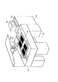
次に、図3は、上記のカラーフィルタ製造装置90に使用されるインクジェットヘッドIJHの構造を示す図である。図1の装置においては、インクジェットヘッドはR,G,Bの3色に対応して3個設けられているが、これらの3個のヘッドは夫々同一の構造であるので、図3にはこれらの3個のヘッドのうちの1つの構造を代表して示している。
【0036】
図3において、インクジェットヘッドIJHは、インクを加熱するための複数のヒータ102が形成された基板であるヒータボード104と、このヒータボード104の上にかぶせられる天板106とから概略構成されている。天板106には、複数の吐出口108が形成されており、吐出口108の後方には、この吐出口108に連通するトンネル状の液路110が形成されている。各液路110は、隔壁112により隣の液路と隔絶されている。各液路110は、その後方において1つのインク液室114に共通に接続されており、インク液室114には、インク供給口116を介してインクが供給され、このインクはインク液室114から夫々の液路110に供給される。
【0037】
ヒータボード104と、天板106とは、各液路110に対応した位置に各ヒータ102が来る様に位置合わせされて図3の様な状態に組み立てられる。図3においては、2つのヒータ102しか示されていないが、ヒータ102は、夫々の液路110に対応して1つずつ配置されている。そして、図3の様に組み立てられた状態で、ヒータ102に所定の駆動パルスを供給すると、ヒータ102上のインクが沸騰して気泡を形成し、この気泡の体積膨張によりインクが吐出口108から押し出されて吐出される。従って、ヒータ102に加える駆動パルスを制御、例えば電力の大きさを制御することにより気泡の大きさを調整することが可能であり、吐出口から吐出されるインクの体積を自在にコントロールすることができる。
【0038】
図4は、カラーフィルタの製造工程の例を示した図である。
【0039】
本発明のカラーフィルタにおいては、基板として透光性の基板が好ましく、一般にガラス基板が用いられるが、液晶用カラーフィルタとしての透明性、機械的強度等の必要特性を有するものであればガラス基板に限定されるものではない。図4(a)は、光透過部7と遮光部であるブラックマトリクス2を備えたガラス基板1を示す。まず、ブラックマトリクス2の形成された基板1上に光照射又は光照射と加熱により硬化可能であり且つインク受容性を有する樹脂組成物を塗布し、必要に応じてプリベークを行って樹脂層3を形成する(図4(b))。樹脂層3の形成には、スピンコート、ロールコート、バーコート、スプレーコート、ディップコート等の塗布方法を用いることができ、特に限定されるものではない。
【0040】
次に、ブラックマトリクス2により遮光される部分の樹脂層をフォトマスク4を使用して予めパターン露光を行うことにより樹脂層の一部を硬化させてインクを吸収しない部位5(非着色部位)を形成し(図4(c))、その後インクジェットヘッドを用いてR、G、Bの各色を一度に着色し(図4(d))、必要に応じてインクの乾燥を行う。
【0041】
パターン露光の際に使用されるフォトマスク4としては、ブラックマトリクスによる遮光部分を硬化させるための開口部を有するものを使用する。この際、ブラックマトリクスに接する部分での着色剤の色抜けを防止するために、比較的多くのインクを付与することが必要である。そのためにブラックマトリクスの(遮光)幅よりも狭い開口部を有するマスクを用いることが好ましい。
【0042】
着色に用いるインクとしては、染料系、顔料系共に用いることが可能であり、また液状インク、ソリッドインク共に使用可能である。
【0043】
本発明で使用する硬化可能な樹脂組成物としては、インク受容性を有し、且つ光照射又は光照射と加熱の少なくとも一方の処理により硬化し得るものであればいずれでも使用可能であり、樹脂としては例えばアクリル系樹脂、エポキシ樹脂、シリコン樹脂、ヒドロキシプロピルセルロース、ヒドロキシエチルセルロース、メチルセルロース、カルボキシメチルセルロースなどのセルロース誘導体あるいはその変性物等が挙げられる。
【0044】
これらの樹脂を光あるいは光と熱により架橋反応を進行させるために光開始剤(架橋剤)を用いることも可能である。光開始剤としては、重クロム酸塩、ビスアジド化合物、ラジカル系開始剤、カチオン系開始剤、アニオン系開始剤等が使用可能である。またこれらの光開始剤を混合して、あるいは他の増感剤と組み合わせて使用することもできる。更にオニウム塩などの光酸発生剤を架橋剤として併用することも可能である。なお、架橋反応をより進行させるために光照射の後に熱処理を施してもよい。
【0045】
これらの組成物を含む樹脂層は、非常に耐熱性、耐水性等に優れており、後工程における高温あるいは洗浄工程に十分耐え得るものである。
【0046】
本発明で使用するインクジェット方式としては、エネルギー発生素子として電気熱変換体を用いたバブルジェットタイプ、あるいは圧電素子を用いたピエゾジェットタイプ等が使用可能であり、着色面積及び着色パターンは任意に設定することができる。
【0047】
また、本例では基板上にブラックマトリクスが形成された例を示しているが、ブラックマトリクスは、硬化可能な樹脂組成物層を形成後、あるいは着色後に樹脂層上に形成されたものであっても特に問題はなく、その形態は本例に限定されるものではない。また、その形成方法としては、基板上にスパッタもしくは蒸着により金属薄膜を形成し、フォトリソ工程によりパターニングすることが好ましいが、これに限定されるものではない。
【0048】
次いで光照射のみ、熱処理のみ、又は光り照射及び熱処理を行って硬化可能な樹脂組成物を硬化させ(図4(e))、必要に応じて保護層8を形成(図4(f)する。なお、図中hνは光の強度を示し、熱処理の場合は、hνの光の代わりに熱を加える。保護層8としては、光硬化タイプ、熱硬化タイプあるいは光熱併用タイプの第2の樹脂組成物を用いて形成するか、あるいは無機材料を用いて蒸着またはスパッタによって形成することができ、カラーフィルタとした場合の透明性を有し、その後のITO形成プロセス、配向膜形成プロセス等に十分耐えうるものであれば使用可能である。
【0049】
図5乃至図7は上記のカラーフィルタを組み込んだカラー液晶表示装置30の基本構成を示す断面図である。
【0050】
カラー液晶表示装置は、一般的にカラーフィルタ54と対向基板24を合わせこみ、液晶化合物18を封入することにより形成される。液晶表示装置の一方の基板21より内側に、TFT(Thin Film Transistor)(不図示)と透明な画素電極20がマトリクス状に形成される。また、もう一方のガラス基板1より内側に、画素電極に対向する位置にRGBの色材が配列されるようにして、カラーフィルタ54が構成され、その上に透明な対向電極(共通電極)16が一面に形成される。ブラックマトリクス2は、通常カラーフィルター基板54側に形成されるが(図5参照)、BM(ブラックマトリクス)オンアレイタイプの液晶パネルにおいては対向するTFT基板(対向基板24)側に形成される(図6参照)。さらに、両基板の面内には配向膜19が形成されており、これをラビング処理することにより液晶分子を一定方向に配列させることができる。また、それぞれのガラス基板の外側には偏光板11,22が接着されており、液晶化合物18は、これらのガラス基板の間隙(2〜5μm程度)に充填される。また、バックライトとしては蛍光灯(不図示)と散乱板(不図示)の組み合わせが一般的に用いられており、液晶化合物をバックライト光の透過率を変化させる光シャッターとして機能させることにより表示を行う。
【0051】
また、図7に示すように、画素電極20上に着色部を形成し、カラーフィルタとして機能させるようにしても良い。すなわち、カラーフィルタを構成する着色部は、ガラス基板上に形成されることに限定されるものではない。なお、図7に示す形式においては、画素電極上にインク受容層を形成し、この受容層にインクを付与する場合と、画素電極上に色材を混入した樹脂インクを直射ちする場合とがある。
【0052】
このような液晶表示装置を情報処理装置に適用した場合の例を図8乃至図10を参照して説明する。
【0053】
図8は上記の液晶表示装置をワードプロセッサ、パーソナルコンピュータ、ファクシミリ装置、複写装置としての機能を有する情報処理装置に適用した場合の概略構成を示すブロック図である。
【0054】
図中、1801は装置全体の制御を行う制御部で、マイクロプロセッサ等のCPUや各種I/Oポートを備え、各部に制御信号やデータ信号等を出力したり、各部よりの制御信号やデータ信号を入力して制御を行っている。1802はディスプレイ部で、この表示画面には各種メニューや文書情報及びイメージリーダ1807で読み取ったイメージデータ等が表示される。1803はディスプレイ部1802上に設けられた透明な感圧式のタッチパネルで、指等によりその表面を押圧することにより、ディスプレイ部1802上での項目入力や座標位置入力等を行うことができる。
【0055】
1804はFM(Frequency Modulation)音源部で、音楽エディタ等で作成された音楽情報をメモリ部1810や外部記憶装置1812にデジタルデータとして記憶しておき、それらメモリ等から読み出してFM変調を行うものである。FM音源部1804からの電気信号はスピーカ部1805により可聴音に変換される。プリンタ部1806はワードプロセッサ、パーソナルコンピュータ、ファクシミリ装置、複写装置の出力端末として用いられる。
【0056】
1807は原稿データを光電的に読取って入力するイメージリーダ部で、原稿の搬送経路中に設けられており、ファクシミリ原稿や複写原稿の他各種原稿の読取りを行う。
【0057】
1808はイメージリーダ部1807で読取った原稿データのファクシミリ送信や、送られてきたファクシミリ信号を受信して復号するファクシミリ(FAX)の送受信部であり、外部とのインタフェース機能を有する。1809は通常の電話機能や留守番電話機能等の各種電話機能を有する電話部である。
【0058】
1810はシステムプログラムやマネージャープログラム及びその他のアプリケーションプログラム等や文字フォント及び辞書等を記憶するROMや、外部記憶装置1812からロードされたアプリケーションプログラムや文書情報、さらにはビデオRAM等を含むメモリ部である。
【0059】
1811は文書情報や各種コマンド等を入力するキーボード部である。
【0060】
1812はフロッピーディスクやハードディスク等を記憶媒体とする外部記憶装置で、この外部記憶装置1812には文書情報や音楽あるいは音声情報、ユーザのアプリケーションプログラム等が格納される。
【0061】
図9は図8に示す情報処理装置の模式的概観図である。
【0062】
図中、1901は上記の液晶表示装置を利用したフラットパネルディスプレイで、各種メニューや図形情報及び文書情報等を表示する。このディスプレイ1901上ではタッチパネル1803の表面は指等で押圧することにより座標入力や項目指定入力を行うことができる。1902は装置が電話機として機能するときに使用されているハンドセットである。キーボード1903は本体と着脱可能にコードを介して接続されており、各種文書機能や各種データ入力を行うことができる。また、このキーボード1903には各種機能キー1904等が設けられている。1905は外部記憶装置1812へのフロッピーディスクの挿入口である。
【0063】
1906はイメージリーダ部1807で読取られる原稿を載置する用紙載置部で、読取られた原稿は装置後部より排出される。またファクシミリ受信等においては、インクジェットプリンタ1907よりプリントされる。
【0064】
上記情報処理装置をパーソナルコンピュータやワードプロセッサとして機能する場合、キーボード部1811から入力された各種情報が制御部1801により所定のプログラムに従って処理され、プリンタ部1806に画像として出力される。
【0065】
ファクシミリ装置の受信機として機能する場合、通信回線を介してFAX送受信部1808から入力したファクシミリ情報が制御部1801により所定のプログラムに従って受信処理され、プリンタ部1806に受信画像として出力される。
【0066】
また、複写装置として機能する場合、イメージリーダ部1807によって原稿を読取り、読取られた原稿データが制御部1801を介してプリンタ部1806に複写画像として出力される。なお、ファクシミリ装置の受信機として機能する場合、イメージリーダ部1807によって読取られた原稿データは、制御部1801により所定のプログラムに従って送信処理された後、FAX送受信部1808を介して通信回線に送信される。
【0067】
なお、上述した情報処理装置は図10に示すようにインクジェットプリンタを本体に内蔵した一体型としてもよく、この場合は、よりポータブル性を高めることが可能となる。同図において、図9と同一機能を有する部分には、対応する符号を付す。
【0068】
図11はカラーフィルタの着色方法を示した図であり、図1において同一基板上に複数形成されているカラーフィルタの内の1つを上方から見たものである。
【0069】
図11の各要素を下側の層から順に説明する。101はカラーフィルタ基板(図4の基板1に対応)で、102はカラーフィルタ基板101上に形成されたブラックマトリクス(図4のブラックマトリクス2に対応)であり、遮光性をもつ。103はブラックマトリクス102に設けられた開口部(図4の光透過部7に対応)である。ブラックマトリクス102の上にはインク受容層(図4の樹脂層3に対応)が形成され、インクにより着色される。インク受容層にはブラックマトリクス102の横方向に隣り合う開口部の間に、紫外線照射により撥水性となった部分(図4の非着色部5に対応)がストライプ状に形成されている。104はインク受容層の着色部を示しており、図12に示す様に、受容層に着弾したインク202が互いに混ざり合い、図11の104のような範囲に広がったものである。55は、図1に示したようにカラーフィルタを着色するインクジェットヘッドユニットで、各色(赤R、緑G、青B)毎に別々のインクジェットヘッド55b,55c,55dを備えている。インクジェットヘッド55b,55c,55dは長手方向に複数のノズル(図示せず)を持ち、ノズルピッチが着色部の画素ピッチに一致するように基板101と平行な平面内において傾けて設置されている。インクジェットヘッドユニット55は、基板101に対して相対的に矢印Aで示す方向に走査されながらインクを吐出し、各画素列を着色する。
【0070】
ところで、このような着色方法を行うときに、1408といった多数のインク吐出ノズルを有する長尺状のインクジェットヘッドを用いる場合、本願発明者らは、連続した着色を繰り返していくと、インクジェットヘッドの中央部のインク吐出量が低下するという現象を見出した。
【0071】
図13は、この様子を示した図であり、着色走査を繰り返していく毎に、インクジェットヘッドの中央部のノズルで着色されたカラーフィルタの部分の色濃度が低下していることが分かる。なお、この実験においては、図14に示すように、多数のインク吐出ノズル302に対応して長尺状に形成されたインク液室304の両端部にインク供給口306,308を有するインクジェットヘッド300を用いている。
【0072】
このインクジェットヘッドの中央部でインク吐出量が低下する原因を明確にするために、図14に示すように、2つのインク供給口の一方を塞ぎ、連続したインク吐出を繰り返して、その吐出量を調べる実験を行った。図14(a)は、右側のインク供給口308を塞いだ場合を示し、図14(b)は、左側のインク供給口306を塞いだ場合を示している。
【0073】
図15は、このときのインク吐出量の低下の状態を示した図である。
【0074】
この図によれば、右側のインク供給口308を塞いだ場合には、図15(a)に示すように、着色走査を繰り返すうちに、塞いだ右側のインク供給口308の近くのインク吐出ノズルの吐出量が低下していくことが分かる。また、左側のインク供給口306を塞いだ場合には、図15(b)に示すように、同じく塞いだインク供給口306側のインク吐出ノズルの吐出量が低下していくことが分かる。
【0075】
なお、実験に際しては、インク吐出の安定性を向上させるためにインク内の溶存酸素量を1ppm以下として吐出を行っている。また、インクジェットヘッドとしては、既に述べたようにインク供給口が両端にあるヘッドで、ノズル数1408、ヘッド長約100mmのものを使用した。
【0076】
また、本願発明者らの実験により、インク中の溶存酸素量が1ppm以下の場合と7ppm程度の場合では、図16に示すように、インク中の溶存酸素が高い7ppm程度のインクを用いた場合のほうが、吐出量が低下しやすいことも分かっている。
【0077】
以上の結果から、本願発明者らは次のような現象が発生していると考えた。
【0078】
即ち、インクの吐出を繰り返すと、図17(a)に示すように、インクを吐出すること(発泡)により発生する微小な残留泡や部分的に溶存酸素が増加したインクがインク液室304内に溜まる。インクを両方のインク供給口306,308からインク液室304に供給する場合、両方のインク供給口306,308から吐出により不足したインクがリフィルされ、それにより、図17(b)に示すように、インク液室304の中央部でリフィルインクの流れが衝突し、中央部に、微小な残留泡や溶存酸素が増加したインクが滞留する。
【0079】
図3に示したような、インクを加熱し、その時発生する気泡の成長によりインクを吐出する所謂バブルジェットタイプのインクジェットヘッドでは、発泡の力が衝撃波となってインク中を伝播するが、このときに溶存酸素量が多いと、溶存酸素が析出し微小な残留気泡がダンパーとなり、発泡の力がうまく伝わらずに吸収されて伝達効率が低下する。そのため上記のようにインク液室304の中央部に微小な残留泡や溶存酸素が増加したインクが滞留すると、その部分のインク吐出ノズルからのインク吐出量が低下してしまう。
【0080】
これに対し、例えば図17(c)に示すように、一方のインク供給口308を塞いだ場合には、塞いでいないインク供給口306から吐出により不足したインクがリフィルされる。これにより、インク液室304内に図17(c)に示すようなインクの流れが生じ、インク液室304内の、塞いだインク供給口308側に、微小な残留泡や部分的に溶存酸素が増加したインクが滞留する。このために、塞いだインク供給口308側のノズルのインク吐出量が低下し、図15(a)に示すようにインク供給口308側のノズルで着色したカラーフィルタの部分の色濃度が低下してしまう。
【0081】
これを解決するために、本実施形態においては、カラーフィルタの着色中に、インクをインク液室304の一方のインク供給口306からもう一方のインク供給口308に向けて低速で循環させ、インク液室304内の微小な残留泡や溶存酸素の部分的に増加したインクをインク液室304外に押し出すことにより、長時間にわたってインク吐出を安定化させるようにしている。
【0082】
実験では、インクを循環させる方法として、図19に示すように、インクのサブタンクをインクジェットヘッド300よりも高い位置に配置し、その高低差によりインクをインク液室内に送り込む方法と、図20に示すように、インクをノズルから漏れない程度にタービンポンプを使って送り込む方法とを用いた。インクの流量は、0.2〜6cc/min程度としたが、インクジェットヘッドを着色のために1回走査する間にインク液室304内のインクがちょうど全て入れ替わる程度の流量とするのが好ましい。
【0083】
なお、図19の場合では、サブタンクとメインタンク側に排出する位置との高低差を調整することによりインクの流量を変更させることができ、また、サブタンク内のインクが減少してくると、メインタンクからインクをポンプでくみ上げ、サブタンク内に供給するようになされている。
【0084】
また、図20の場合では、ヘッドのインク供給側にポンプを設ける態様と、ヘッドのインク排出側にポンプを設ける態様の2つが考えられる。インク供給側にポンプを設ける態様の場合、ポンプを開放型のプロペラポンプとすることで、ポンプとヘッド間の経路につまりが生じても無理な力がかかることがなく破損を防止できるが、一方、ヘッド内が異常に高い正圧となったときインクがヘッドから漏れる虞がある。これに対し、ヘッドのインク排出側にポンプを設けた場合には、ヘッド内は常に負圧となり、インク漏れを防ぐことができ、好ましい。
【0085】
以上のようにして、インクを循環させてカラーフィルタを着色した結果を、図21に示す。
【0086】
図21によれば、インクを循環させてインク液室304内から微小な残留泡や溶存酸素が部分的に増加したインクを除去することにより、着色走査を繰り返してもインクの吐出量が変動しないことが分かる。また、本願発明者らの更なる実験によれば、ヘッドの長さが1インチ以上ある場合に、特に本実施形態のインクを循環させる方法が有効であることが分かった。また、インクの循環は、インクジェットヘッドがインク吐出を休止している間も連続して行うことが好ましい。
【0087】
なお、既に説明したバブルジェット方式のインクジェットヘッドでは、気泡を発生させてインクを吐出するので、ピエゾ素子を使用した場合に比べて消泡できなかった部分がインク液室に残りやすいので、インクを循環させることは、バブルジェット方式の場合特に有効である。
【0088】
また、本実施形態のインクを循環させる方法を用いることにより、インクジェットヘッドの吐出回復の動作の回数や量が減り、インクの無駄を低減することができる。
【0089】
次に、上記のようにインクを循環させることにより、どの程度インクの吐出量低下を防止できるか、言い換えれば、ノズル毎のインク吐出量のバラつきを測定する方法について説明する。
【0090】
図22は、インク吐出量の測定装置の構成を示す図である。図22において、401は濃度を測定する画像処理装置、402は画像処理装置及びXY制御ステージ404を制御するパーソナルコンピュータ(以下、PC)、403は画像を拡大するための拡大光学系、404は測定対象物の濃度を連続的に測定する場合のXY制御ステージ、405は測定対象物の画像を画像処理装置に取り込むラインセンサカメラ、406はXY制御ステージ404の下に設置された透過光源である。XY制御ステージ404のステージ表面は中心部分がガラスになっており透過光源406を利用して測定対象物を透過照明でラインセンサカメラ405に取り込むことができる。これにより、本構成ではラインセンサカメラ405と光源406の位置関係は固定となる。PC402はXY制御ステージ404をRS232CあるいはGPIBインターフェースを用いて制御するとともに、画像処理装置401も制御する。
【0091】
図23はインクジェットヘッドで複数の異なるノズルを用いてガラス基板410上にラインパターンを描画したものである。また、図中の同一ノズル方向及び異ノズル方向は、それぞれ同一ノズルから吐出されたインクによるラインパターンの延長方向と異ノズルから吐出されたインクによるラインパターンの並び方向を示している。ここで、単なるガラス基板に通常のインクを吐出してもインクは弾かれてしまうためガラス基板410上にはインクを受け止める特殊な処理(本実施形態ではインク吸収性のある組成物層412としてポリビニルアルコールを塗布した)を施しておいた方がよい。この処理により各ノズルから吐出されたインクは組成物層412で均一的に吸収され図23に示すようなラインパターンを形成する。組成物層412にはできる限り無色透明に近い(透過光を吸収しない)ものが望ましいことは言うまでもない。なお、樹脂含有インク等をガラス基板に吐出することでインクをはじかなくすることも可能である。
【0092】
図23のように描画したラインパターンに拡大光学系403の焦点を合わせ、拡大倍率及び透過光源406の強度を適当に設定した状態で、ラインセンサカメラ405を通してその画像を画像処理装置401に取り込む。なお、本実施形態では拡大倍率を5倍としたがこれに限定されるものではないことは言うまでもない。ラインセンサカメラ405は白黒のものである。そして、このラインセンサカメラ405から取り込まれた画像は、画像処理装置が分解しうる最小画素単位で構成され(本装置は8ビットのA/D変換素子を使用)、その最小画素は各画素点での透過光の強度に応じて0〜255までの256段階の輝度レベルを表現できる様に構成されている。
【0093】
次にラインパターンの濃度(これは、各ノズルのインク吐出量に相当するものである)を測定する方法について説明する。
【0094】
本実施形態では、濃度という概念を次式で表わす。
【0095】
画素濃度=Log(画素参照輝度/画素輝度) (1)
この考えを更に詳しく説明する。本実施形態ではラインパターンの濃度を、透過光が、色(濃度)を持つ測定対象のラインパターンを通過する際にどれだけ吸収されるかによって判断している。つまり、測定対象ラインパターンの濃度が高ければ透過光はより吸収され弱まる。即ち、その測定対象ラインパターンの範囲内にある最小画素の輝度レベルは低くなる。逆に濃度が低ければ最小画素の輝度レベルは高くなるはずである。本実施形態ではこの点に着目して濃度を透過光の吸収率(実際に画像処理で求めているのは輝度レベルであるが)に置き換えている。
【0096】
そこで、上記で説明したようにラインセンサカメラを用いて取り込んだ測定対象ラインパターンの画像に対して図24に示したような固定サイズの枠(以下、ウインドウと呼ぶ)をかける。そして、このウインドウは図25に示すようにn×mの画素から構成されている(ラインセンサカメラを用いているので、ラインパターンの幅方向にm画素分走査して、図25のような画像を得る)。ここで、各画素の輝度レベル(画素輝度:Qnm)を求める。また、同サイズのウインドウをラインパターンのない部分(素ガラス部分)で取り込んだ画像にかけて、そのときの各画素の輝度レベル(画素参照輝度:Inm)を求めておく。これが、図25の破線のウインドウが示すものである。こうして、対応する画素毎において、前述の式(1)に基づいて、
画素濃度Dnm=Log(画素参照輝度Inm/画素輝度Qnm) (2)
を算出する。この式により算出されるのは、各画素毎の濃度であるので、この画素濃度Dnmをn=1〜n、m=1〜mについてすべて加算(即ちウインドウ内のすべての画素の濃度を加算)して、ウインドウ内全体の濃度を求める。
【0097】
ウインドウのサイズは測定するラインパターンの大きさを考慮して適当に決定すればよい(ただし、ウインドウの大きさは少なくともラインパターン全体が完全に含まれる大きさ以上でなければならない)。仮に、ラインパターンよりもかなり大きいウインドウをかけたとしてもラインパターンの周囲の濃度の薄い画素(素ガラス部分に相当する画素)では、Inm≒Qnmとなるので、これを(2)式に代入すると、
画素濃度Dnm=Log(Inm/Qnm)≒Log1=0 (3)
となる。すなわち、ラインパターンよりも大きいウインドウをかけたとしてもラインパターンの周囲の濃度の薄い画素は、画素濃度≒0となり、これを加算したとしてもウインドウ内の画素濃度の加算値は殆ど変化しない。言い換えれば、ラインパターンに大きいウインドウをかけたとしても、実質的には、ラインパターン部分の濃度だけが求められることになる。従って、本実施形態の方法によれば、ウインドウのサイズによらず正しいラインパターン濃度を算出することができることとなる。
【0098】
そして、XYステージ404をPC402を用いて制御することにより連続してラインパターンを読み取り、その後、ウインドウをかけることにより全てのラインパターンの濃度を求めることができる。
【0099】
こうして求めたラインパターンの濃度から、後に述べる検量線を用いてラインパターンを描画したノズルの1回の吐出あたりのインク量を求める。
【0100】
なお、上記で求めたラインパターンの濃度は、ラインパターンが例えば50発のインクで形成されているならば、50発分のインクが形成するインクドットの濃度の和となる。そのため、検量線から1回あたりのインク吐出量を求めるためには、ラインパターンを形成したときのインク吐出数で、ラインパターンの濃度を割った値をデータとして用いる。
【0101】
なお、ラインパターンの濃度を求めるにあたって、1ラインパターン全ての濃度としなくても、例えば1/2の長さ(25発分)等で濃度を求めてもよい。
【0102】
次に、インクジェットヘッドの任意のノズルから任意の条件下で吐出された1回当たりのインク吐出量を測定する基準となる検量線を求める方法について説明する。なお、ここで1回当たりのインク吐出量とは、通常は1滴のインクの量を指すが、インクは場合によっては滴状にならない場合もあるので、1滴とは表現せずに1回当たりのインク吐出量という表現にしている。
【0103】
まず、最初の作業として、吐出量を測定しようとするインクジェットヘッドの複数のノズルのうち、一定条件下での1回の吐出量がなるべく異なる少なくとも2つ以上のノズルの吐出量を重量法あるいは吸光度法で求めておく。
【0104】
本実施形態では、一定条件下での吐出量の異なる4つのノズルの1回あたりの吐出量を予め重量法を用いて求めた。
【0105】
次に、このようにして1回あたりの吐出量が判明した4つのノズルから、吐出量を求めたときと同じ条件下でインクを吐出させ、これらのインクがガラス基板410上に形成するラインパターン(あるいはインクドットでもよい)の濃度を前述したような方法で測定する。このような測定を行うことにより、4つのノズルにおけるインクの吐出量を4ノズルの作るラインパターンから求めることができる。
【0106】
図26は、上記の4つのノズルについて、インクの1回の吐出量と、そのインクがガラス基板410上に形成するインクドットの濃度の関係をグラフ上にプロットしたものである。図26中で、黒丸で示したものが、4つのノズルのインク吐出量とインクドット濃度を示す点である。この図を見ると、4つの点が略一直線上にあることがわかる。従って、これら4つの点を通る直線を引けば、この直線上の点として任意の吐出量に対するインクドットの濃度が一義的に求められることとなる。この直線を検量線と呼ぶことにする。
【0107】
なお、この検量線は直線で表わされることから、検量線を求めるためには、グラフ上に最低2個の点がプロットできればよい。従って、上記の様に4つの異なるノズルを使用しなくとも、最低2つのノズルを使用するだけでも検量線を求めることは可能である。但し、本実施形態では、検量線を求める上で重量法あるいは吸光度法によるインク吐出量のデータを使用するためそれぞれの測定法の精度はそのまま本実施形態における吐出量測定の精度に影響する。そのため検量線は3つ以上のノズルを使用して求めることがより望ましいと考えられる。また、検量線は使用するインクが変わる毎に再度求める必要があることは言うまでもない。
【0108】
以後、任意のノズルにより任意の条件下で吐出したラインパターンの濃度を上記手法により測定し、上記の検量線からそのノズルのインク吐出量を求めることができる。
【0109】
なお、一旦求めた検量線のデータをPC402内のメモリに記憶しておけば、濃度測定データを瞬時に吐出量のデータに変換することがPC402を使用することで容易に実現される。
【0110】
ここでは記録を行ったラインパターンに基づいて濃度測定及び検量線を求める例を示したが、インクドットパターンからも同様に求めることができる。
【0111】
この場合、インクドットの測定は50ドットの平均値から求める。また、その際に濃度測定用のパターンは図27のようなパターンであり、前述した枠サイズの掛け方は例えば図28のように行い、ウインドウを掛けた場合の画像を図29に示している。このウインドウに基づく濃度の検出方法は前述した方法と同様の方法をとればよい。
【0112】
以上説明したようなラインパターンもしくはドットパターンを用いたインク吐出量の測定方法から、カラーフィルタの作成を開始する前に、インクジェットヘッド300のノズル毎の1回あたりのインク吐出量を測定した。そして、この時の各ノズルの吐出量を規定値である”1”とした。
【0113】
吐出量のずれの検出については、所定枚のカラーフィルタを製造した後に、再度上述のような方法によって各ノズルの吐出量を求め、カラーフィルタの作成前の規定値からのずれを全ノズルに亘って調べ、その3σの値によってずれの吐出量の変動率の大小を判断した。
【0114】
本実施形態においては、吐出量の変動率に応じて、作成されたカラーフィルタの官能評価の合格率を検討した結果次のような結果を得た。なお、官能評価の基準は目視により認識できる欠陥があるか否かによって行った。
【0115】
その結果によると、吐出量の変動率が±1%以下では、認識できる欠陥はなく官能評価合格率は100%であった。吐出量の変動率が±1%より大きく±2%以下の場合には官能評価は70%であった。また、吐出量の変動率が±2%より大きく±3%以下の場合には官能評価は20%であった。吐出量の変動率が±3%より大きい場合には官能評価は0%であった。
【0116】
このことから、吐出量のばらつき(変動率)が±3%以内であれば良好なカラーフィルタを製造することができ、好ましくは±2%以下であればよく、さらに±1%以下では最も望ましい。
【0117】
本実施形態の、インクタンクからインクジェットヘッド300内のインク液室304にインクを循環させる方法を用いれば、より多くのカラーフィルターを製造するために、より多くの回数インクの吐出を繰り返しても、ノズル毎のインク吐出量(吐出体積)の変動率を上記の±3%の変動率の範囲内に長期に亘って抑えることができ、高品位なカラーフィルタを製造することが可能であった。
【0118】
以下に、図30を用いて、本実施形態におけるカラーフィルタの製造の全体シーケンスについて説明する。
【0119】
まず、カラーフィルタの製造前に各ノズルからのインクの吐出量をステップS2で測定する。各ノズルの吐出量にしたがって、カラーフィルタ製造時の吐出ピッチを計算し、各ノズルで形成される吐出ラインの濃度(カラーフィルタの画素)が均一になるように吐出ピッチを設定する(ステップS4)。このとき、各ノズルの吐出量の規定値を前述のように規定する。設定したピッチでカラーフィルタを生産し(ステップS6)、定期的に描画した測定用のラインもしくはカラーフィルタの画素をそのまま用いて濃度測定(吐出量測定)を行い、その吐出量がカラーフィルタ製造時の吐出ピッチを決定した際の吐出量から各ノズル(各画素)の吐出量のずれの変動率3σが前述の±3%以内か否かの判断を行う(ステップS8)。±3%以内の場合にはカラーフィルタの製造を継続する。±3%より大きい場合には、規定枚数以上の生産ができたか否かの判断を行い(ステップS10)、規定枚数以下の場合には、ヘッドの寿命と判断しヘッドを交換する(ステップS12)。規定枚数より大きい場合には、ステップS4に戻って再度記録密度を設定し直す。
【0120】
このようなシーケンスを行うことで、ヘッドの吐出量の変動を規定値以内に抑えて着色を行うことができ、良好なカラーフィルターをより長期にわたって製造することができる。
【0121】
なお、本発明は、その主旨を逸脱しない範囲で、上記実施形態を修正又は変形したものに適用可能である。
【0122】
例えば、近年TFTアレイ側にカラーフィルタを設けたパネルも存在するが、本明細書で定義しているカラーフィルタは、色材により着色された被着色体であり、TFTアレイ側にあるか否かにかかわらず、どちらも包含する。
【0123】
例えば、本発明においては、ノズル毎のインクの吐出量(吐出体積)の変動率に対して規定してあるが、複数のノズルを用いてカラーフィルタの画素の着色を行っている場合は、各画素の着色を行う夫々のノズルのインク吐出量(吐出体積)の総和である各画素毎のインク吐出量(吐出体積)の変動率が既定値以内である時に着色部を形成し、その範囲を超えた場合に吐出密度を再設定するとした場合も包含する。すなわち、カラーフィルターそのものを測定して各画素の吐出量を求める場合も包含する。
【0124】
本発明は、特にインクジェット記録方式の中でも、インク吐出を行わせるために利用されるエネルギーとして熱エネルギーを発生する手段(例えば電気熱変換体やレーザ光等)を備え、前記熱エネルギーによりインクの状態変化を生起させる方式のプリント装置について説明したが、かかる方式によれば記録の高密度化、高精細化が達成できる。
【0125】
その代表的な構成や原理については、例えば、米国特許第4723129号明細書、同第4740796号明細書に開示されている基本的な原理を用いて行うものが好ましい。この方式はいわゆるオンデマンド型、コンティニュアス型のいずれにも適用可能であるが、特に、オンデマンド型の場合には、液体(インク)が保持されているシートや液路に対応して配置されている電気熱変換体に、記録情報に対応していて膜沸騰を越える急速な温度上昇を与える少なくとも1つの駆動信号を印加することによって、電気熱変換体に熱エネルギーを発生せしめ、記録ヘッドの熱作用面に膜沸騰を生じさせて、結果的にこの駆動信号に1対1で対応した液体(インク)内の気泡を形成できるので有効である。この気泡の成長、収縮により吐出用開口を介して液体(インク)を吐出させて、少なくとも1つの滴を形成する。この駆動信号をパルス形状をすると、即時適切に気泡の成長収縮が行われるので、特に応答性に優れた液体(インク)の吐出が達成でき、より好ましい。
【0126】
このパルス形状の駆動信号としては、米国特許第4463359号明細書、同第4345262号明細書に記載されているようなものが適している。なお、上記熱作用面の温度上昇率に関する発明の米国特許第4313124号明細書に記載されている条件を採用すると、さらに優れた記録を行うことができる。
【0127】
記録ヘッドの構成としては、上述の各明細書に開示されているような吐出口、液路、電気熱変換体の組み合わせ構成(直線状液流路または直角液流路)の他に熱作用面が屈曲する領域に配置されている構成を開示する米国特許第4558333号明細書、米国特許第4459600号明細書を用いた構成も本発明に含まれるものである。加えて、複数の電気熱変換体に対して、共通するスロットを電気熱変換体の吐出部とする構成を開示する特開昭59−123670号公報や熱エネルギーの圧力波を吸収する開口を吐出部に対応させる構成を開示する特開昭59−138461号公報に基づいた構成としても良い。
【0128】
さらに、記録装置が記録できる最大記録媒体の幅に対応した長さを有するフルラインタイプの記録ヘッドとしては、上述した明細書に開示されているような複数記録ヘッドの組み合わせによってその長さを満たす構成や、一体的に形成された1個の記録ヘッドとしての構成のいずれでもよい。
【0129】
加えて、装置本体に装着されることで、装置本体との電気的な接続や装置本体からのインクの供給が可能になる交換自在のチップタイプの記録ヘッド、あるいは記録ヘッド自体に一体的にインクタンクが設けられたカートリッジタイプの記録ヘッドを用いてもよい。
【0130】
また、本発明の記録装置の構成として設けられる、記録ヘッドに対しての回復手段、予備的な補助手段等を付加することは本発明の効果を一層安定にできるので好ましいものである。これらを具体的に挙げれば、記録ヘッドに対してのキャッピング手段、クリーニング手段、加圧あるいは吸引手段、電気熱変換体あるいはこれとは別の加熱素子あるいはこれらの組み合わせによる予備加熱手段、記録とは別の吐出を行う予備吐出モードを行うことも安定した記録を行うために有効である。
【0131】
以上説明した本発明実施例においては、インクを液体として説明しているが、室温やそれ以下で固化するインクであっても、室温で軟化もしくは液化するものを用いても良く、使用記録信号付与時にインクが液状をなすものであればよい。
【0132】
加えて、積極的に熱エネルギーによる昇温をインクの固形状態から液体状態への状態変化のエネルギーとして使用せしめることで積極的に防止するため、またはインクの蒸発を防止するため、放置状態で固化し加熱によって液化するインクを用いても良い。いずれにしても熱エネルギーの記録信号に応じた付与によってインクが液化し、液状インクが吐出されるものや、記録媒体に到達する時点では既に固化し始めるもの等のような、熱エネルギーの付与によって初めて液化する性質のインクを使用する場合も本発明は適用可能である。このような場合インクは、特開昭54−56847号公報あるいは特開昭60−71260号公報に記載されるような、多孔質シート凹部または貫通孔に液状または固形物として保持された状態で、電気熱変換体に対して対向するような形態としてもよい。本発明においては、上述した各インクに対して最も有効なものは、上述した膜沸騰方式を実行するものである。
【0133】
また、上述の実施形態では、インクを吐出する手段として熱エネルギーを発生する手段を用いて説明したが、これに限らず、ピエゾ素子を用いてもよい。
【0134】
【発明の効果】
以上説明したように、本発明によれば、インク液室内にインク流入口からインク流出口に至るインクの流れを生じさせることにより、インク吐出量の変動を抑え、色むらのないカラーフィルタを製造することができる。
【図面の簡単な説明】
【図1】カラーフィルタの製造装置の一実施形態の構成を示す概略図である。
【図2】カラーフィルタの製造装置の動作を制御する制御部の構成を示す図である。
【図3】カラーフィルタの製造装置に使用されるインクジェットヘッドの構造を示す図である。
【図4】カラーフィルタの製造工程を示した図である。
【図5】一実施形態のカラーフィルタを組み込んだカラー液晶表示装置の基本構成の一例を示す断面図である。
【図6】一実施形態のカラーフィルタを組み込んだカラー液晶表示装置の基本構成の他の例を示す断面図である。
【図7】一実施形態のカラーフィルタを組み込んだカラー液晶表示装置の基本構成のさらに他の例を示す断面図である。
【図8】液晶表示装置が使用される情報処理装置を示した図である。
【図9】液晶表示装置が使用される情報処理装置を示した図である。
【図10】液晶表示装置が使用される情報処理装置を示した図である。
【図11】カラーフィルターの着色方法の概略図である。
【図12】着色直後のカラーフィルタの着色部の概略図である。
【図13】走査毎のカラーフィルタの色むらの発生の仕方を示した図である。
【図14】インクジェットヘッドの概略構成を示す図である。
【図15】走査毎のカラーフィルタの色むらの発生の仕方を示した図である。
【図16】溶存酸素の量とインク吐出量の変動の仕方の関係を示した図である。
【図17】インク液室内の残留泡の滞留の様子を示す図である。
【図18】インク液室にインクを循環させる様子を示す図である。
【図19】インク液室にインクを循環させる構成を示す図である。
【図20】インク液室にインクを循環させる構成を示す図である。
【図21】走査毎にカラーフィルタに色むらが発生しない状態を示した図である。
【図22】インク吐出量の測定装置の構成を示す図である。
【図23】インクジェットヘッドを使用して作成したラインパターンの例を示した図である。
【図24】測定対象ラインパターンに固定サイズのウインドウをかけた例を示した図である。
【図25】ウインドウを各画素毎に区分した様子を示した図である。
【図26】実施形態に基づいた実験で得られた検量線の例を示した図である。
【図27】インクジェットヘッドを使用して作成したドットパターンの例を示した図である。
【図28】測定対象ドットパターンに固定サイズのウインドウをかけた例を示した図である。
【図29】ウインドウを各画素毎に区分した様子を示した図である。
【図30】カラーフィルタの製造の全体シーケンスを示す図である。
【符号の説明】
52 XYθステージ
53 ガラス基板
54 カラーフィルタ
55 着色ヘッド
58 コントローラ
59 ティーチングペンダント
60 キーボード[0001]
BACKGROUND OF THE INVENTION
The present invention relates to a color filter manufacturing method for manufacturing a color filter by coloring a color filter substrate with an inkjet head, a color filter and a display device, a device including the display device, and a discharge volume between a plurality of nozzles by ink circulation. The present invention relates to a method for reducing the variation in the above.
[0002]
[Prior art]
In general, a liquid crystal display device is mounted on a personal computer, a word processor, a pachinko game machine, an automobile navigation system, a small television, and the like, and the demand is increasing in recent years. However, liquid crystal display devices are expensive and demands for cost reduction of liquid crystal display devices are increasing year by year.
[0003]
The color filter constituting the liquid crystal display device is configured by arranging pixels such as red (R), green (G), and blue (B) on a transparent substrate, and further, display contrast is provided around these pixels. In order to increase the brightness, a black matrix for light shielding is provided.
[0004]
Conventionally, pigment dispersion methods, dyeing methods, electrodeposition methods, printing methods and the like are known as methods for producing color filters.
[0005]
In the pigment dispersion method, a photosensitive resin layer in which a pigment is dispersed is formed on a glass substrate, and the process of obtaining a monochromatic pattern by patterning this layer is repeated three times for each of the R, G, and B colors. To form.
[0006]
In the dyeing method, a layer of a water-soluble polymer material, which is a dyeing material, is formed on a glass substrate, formed into a desired pattern by photolithography, and the glass substrate is immersed in a dyeing basket. A color filter is formed by repeating the process of obtaining a colored pattern three times for each of the R, G, and B colors.
[0007]
The electrodeposition method is a process in which a transparent electrode pattern is formed on a glass substrate, and the glass substrate is immersed in an electrodeposition coating solution containing a pigment, a resin, an electrolytic solution, etc., and a single color is electrodeposited. A color filter is formed by repeating three times for each B3 color and firing.
[0008]
In the printing method, the R, G, and B colors are separately applied by repeating printing using a material in which a pigment is dispersed in a thermosetting resin, and then the resin is thermoset.
[0009]
What is common to these four methods is that the same process needs to be repeated three times in order to color the R, G, and B3 colors, and since the number of processes is large, the yield decreases and the cost increases. , And the like.
[0010]
Furthermore, the electrodeposition method is difficult to apply to the TFT because the shape of the pattern that can be formed is limited. Also, the printing method has disadvantages such as poor resolution and difficulty in dealing with pattern miniaturization.
[0011]
Therefore, in order to make up for these drawbacks, a technique for forming a color filter pattern by ejecting ink onto a glass substrate with an inkjet head has been proposed.
[0012]
With regard to such an ink jet method, for example, in Japanese Patent Application Laid-Open No. 59-75205, ink containing three colors of R, G, and B is ejected onto a substrate by an ink jet method, and each ink is dried. It has been proposed to form a colored image portion. In such an ink jet method, it is possible to form each pixel of R, G, and B at once, and a great simplification of the manufacturing process and a great cost reduction effect can be obtained.
[0013]
[Problems to be solved by the invention]
However, in the production of a color filter by the ink jet method, as shown in FIG. 11, coloring of pixels on the same column or row in one screen at a time using an ink jet head having a large number of ink ejection nozzles at a time. When continuously performed, there is a problem in that color unevenness may occur in the screen due to unevenness in the ink discharge amount for each nozzle.
[0014]
Accordingly, the present invention has been made in view of the above-described problems, and an object of the present invention is to provide a color filter manufacturing method capable of manufacturing a color filter with little color unevenness in a short time.
[0015]
Another object of the present invention is to provide a color filter and a display device manufactured by the above-described manufacturing method, and an apparatus including the display device.
[0017]
[Means for Solving the Problems]
In order to solve the above-mentioned problems and achieve the purpose,The color filter manufacturing method according to the present invention includes a plurality of ejection openings, an ink liquid chamber communicating with the plurality of ejection openings, an ink inlet for allowing ink to flow into the ink liquid chamber, and the ink liquid chamber. Of a color filter that uses a plurality of inks ejected from a plurality of ejection ports at a predetermined ejection density using a inkjet head having an ink outlet for allowing ink to flow out from the plurality of ejection ports In the method, the colored portion is formed when a variation rate of an ink volume discharged from the plurality of discharge ports is within ± 3% in order to form the row of colored portions.And the variation rate is calculated based on the result of measuring the transmittance of the colored portions in the row.It is characterized by that.
[0022]
In addition, the color filter manufacturing method according to the present invention includes a plurality of ejection openings, an ink liquid chamber communicating with the plurality of ejection openings, an ink inlet for allowing ink to flow into the ink liquid chamber, and the ink A color filter that uses a plurality of inks ejected from a plurality of ejection openings at a predetermined ejection density using a inkjet head having an ink outlet for allowing ink to flow out of a liquid chamber. A forming step of forming the colored portion when a variation rate of an ink volume discharged from the plurality of discharge ports is within ± 3% to form the row of colored portions; A step of generating an ink flow from the ink inlet to the ink outlet in the ink liquid chamber during ink discharge from the discharge port in the forming step, Link flow, the height of the ink liquid chamber, the height of the height difference of the ink tank containing ink is characterized by being formed by flowing the ink in said ink chamber.
In addition, the color filter manufacturing method according to the present invention includes a plurality of ejection openings, an ink liquid chamber communicating with the plurality of ejection openings, an ink inlet for allowing ink to flow into the ink liquid chamber, and the ink A color filter that uses a plurality of inks ejected from a plurality of ejection openings at a predetermined ejection density using a inkjet head having an ink outlet for allowing ink to flow out of a liquid chamber. The ink flow from the ink inlet to the ink outlet is continuously performed in the ink liquid chamber during ejection of the ink for coloring from the ejection port and a period during which ink is not ejected. FormThe ink flow is formed by flowing ink into the ink liquid chamber according to a height difference between the height of the ink liquid chamber and the height of the ink tank containing the ink.It is characterized by that.
[0027]
A display device manufacturing method according to the present invention is a method of manufacturing a display device including a color filter, the method of manufacturing a color filter by the method of manufacturing a color filter described above, and the manufactured And a step of encapsulating a liquid crystal compound between the color filter and a counter substrate facing the color filter.
[0028]
DETAILED DESCRIPTION OF THE INVENTION
Hereinafter, an embodiment of the present invention will be described in detail with reference to the accompanying drawings.
[0029]
Note that the color filter defined in the present invention includes a colored portion and an object to be colored, and can obtain output light whose characteristics are changed with respect to input light.
[0030]
FIG. 1 is a schematic diagram showing the configuration of a color filter manufacturing apparatus using an ink jet method, and shows a state during the coloring process.
[0031]
In FIG. 1, 51 is an apparatus base, 52 is an XYθ stage disposed on the
[0032]
The
[0033]
FIG. 2 is a configuration diagram of the control controller of the color
[0034]
58 is a controller for controlling the overall operation of the color
[0035]
Next, FIG. 3 is a diagram showing the structure of the inkjet head IJH used in the color
[0036]
In FIG. 3, the ink jet head IJH is generally configured by a
[0037]
The
[0038]
FIG. 4 is a diagram showing an example of the manufacturing process of the color filter.
[0039]
In the color filter of the present invention, a translucent substrate is preferable as the substrate, and a glass substrate is generally used. However, a glass substrate is acceptable as long as it has necessary characteristics such as transparency and mechanical strength as a color filter for liquid crystals. It is not limited to. FIG. 4A shows a
[0040]
Next, a portion 5 (non-colored portion) that does not absorb ink by curing a part of the resin layer by performing pattern exposure in advance on the portion of the resin layer that is shielded by the
[0041]
As the photomask 4 used for pattern exposure, a photomask 4 having an opening for curing a light shielding portion by a black matrix is used. At this time, it is necessary to apply a relatively large amount of ink in order to prevent color loss of the colorant at the portion in contact with the black matrix. Therefore, it is preferable to use a mask having an opening narrower than the (light shielding) width of the black matrix.
[0042]
As the ink used for coloring, both dye-based and pigment-based inks can be used, and both liquid ink and solid ink can be used.
[0043]
As the curable resin composition used in the present invention, any resin composition can be used as long as it has ink acceptability and can be cured by light irradiation or at least one of light irradiation and heating. Examples thereof include acrylic resins, epoxy resins, silicon resins, hydroxypropyl cellulose, hydroxyethyl cellulose, cellulose derivatives such as methyl cellulose, carboxymethyl cellulose, and modified products thereof.
[0044]
It is also possible to use a photoinitiator (crosslinking agent) in order to advance the crosslinking reaction of these resins by light or light and heat. As the photoinitiator, dichromate, bisazide compound, radical initiator, cationic initiator, anionic initiator and the like can be used. Moreover, these photoinitiators can be mixed or used in combination with other sensitizers. Furthermore, a photoacid generator such as an onium salt can be used in combination as a crosslinking agent. In order to further advance the crosslinking reaction, heat treatment may be performed after the light irradiation.
[0045]
The resin layer containing these compositions is extremely excellent in heat resistance, water resistance, etc., and can sufficiently withstand high temperatures in a post-process or a cleaning process.
[0046]
As the ink jet method used in the present invention, a bubble jet type using an electrothermal transducer as an energy generating element, a piezo jet type using a piezoelectric element, or the like can be used, and a coloring area and a coloring pattern can be arbitrarily set. can do.
[0047]
In this example, a black matrix is formed on the substrate. However, the black matrix is formed on the resin layer after forming a curable resin composition layer or after coloring. There is no particular problem, and the form is not limited to this example. Moreover, as a formation method thereof, it is preferable to form a metal thin film on a substrate by sputtering or vapor deposition, and patterning by a photolithography process, but it is not limited to this.
[0048]
Next, the curable resin composition is cured by light irradiation only, heat treatment only, or light irradiation and heat treatment (FIG. 4E), and a protective layer 8 is formed as necessary (FIG. 4F). In the figure, hν represents the intensity of light, and in the case of heat treatment, heat is applied instead of hν.The protective layer 8 has a second resin composition of photocuring type, thermosetting type or photothermal combination type. It can be formed by vapor deposition or sputtering using an inorganic material, has transparency when used as a color filter, and sufficiently withstands subsequent ITO formation process, alignment film formation process, etc. If possible, it can be used.
[0049]
5 to 7 are cross-sectional views showing the basic configuration of a color liquid
[0050]
The color liquid crystal display device is generally formed by combining the
[0051]
Further, as shown in FIG. 7, a colored portion may be formed on the
[0052]
An example in which such a liquid crystal display device is applied to an information processing device will be described with reference to FIGS.
[0053]
FIG. 8 is a block diagram showing a schematic configuration when the above-described liquid crystal display device is applied to an information processing apparatus having functions as a word processor, personal computer, facsimile apparatus, and copying apparatus.
[0054]
In the figure,
[0055]
[0056]
[0057]
[0058]
[0059]
[0060]
An
[0061]
FIG. 9 is a schematic overview of the information processing apparatus shown in FIG.
[0062]
In the figure,
[0063]
[0064]
When the information processing apparatus functions as a personal computer or a word processor, various types of information input from the
[0065]
When functioning as a receiver of a facsimile apparatus, facsimile information input from a FAX transmission /
[0066]
When functioning as a copying apparatus, the original is read by the
[0067]
Note that the above-described information processing apparatus may be an integrated type in which an ink jet printer is built in the main body as shown in FIG. 10, and in this case, it becomes possible to further improve portability. In the figure, parts having the same functions as those in FIG.
[0068]
FIG. 11 is a diagram showing a coloring method of the color filter, and one of the color filters formed on the same substrate in FIG. 1 is viewed from above.
[0069]
Each element in FIG. 11 will be described in order from the lower layer.
[0070]
By the way, when using such a long inkjet head having a large number of ink discharge nozzles such as 1408 when performing such a coloring method, the inventors of the present application repeat the continuous coloring and the center of the inkjet head is repeated. The phenomenon was found that the ink discharge amount of the part decreased.
[0071]
FIG. 13 is a diagram showing this state, and it can be seen that the color density of the color filter portion colored by the nozzle at the center of the inkjet head decreases each time the color scanning is repeated. In this experiment, as shown in FIG. 14, an
[0072]
In order to clarify the cause of the decrease in the ink discharge amount at the center of the ink jet head, as shown in FIG. 14, one of the two ink supply ports is closed, and continuous ink discharge is repeated, and the discharge amount is reduced. An experiment to investigate was conducted. FIG. 14A shows a case where the right
[0073]
FIG. 15 is a diagram showing a state in which the ink discharge amount is reduced at this time.
[0074]
According to this figure, when the right
[0075]
In the experiment, in order to improve the stability of ink ejection, the amount of dissolved oxygen in the ink is 1 ppm or less. Further, as described above, an ink jet head having an ink supply port at both ends and having a nozzle number of 1408 and a head length of about 100 mm was used.
[0076]
Further, according to the experiments by the inventors of the present application, when the amount of dissolved oxygen in the ink is 1 ppm or less and about 7 ppm, as shown in FIG. 16, when about 7 ppm of ink having high dissolved oxygen in the ink is used. It has also been found that the discharge amount tends to decrease.
[0077]
From the above results, the present inventors considered that the following phenomenon occurred.
[0078]
That is, when the ink is repeatedly ejected, as shown in FIG. 17A, fine residual bubbles generated by ejecting the ink (foaming) and ink in which dissolved oxygen partially increases are contained in the
[0079]
In a so-called bubble jet type ink jet head that heats ink and discharges ink by the growth of bubbles generated at that time as shown in FIG. 3, the foaming force propagates through the ink as a shock wave. If the amount of dissolved oxygen is large, the dissolved oxygen precipitates and minute residual bubbles become a damper, which absorbs the foaming force without being transmitted well and lowers the transmission efficiency. For this reason, if the ink in which minute residual bubbles or dissolved oxygen is increased stays in the central portion of the
[0080]
On the other hand, for example, as shown in FIG. 17C, when one
[0081]
In order to solve this, in the present embodiment, during coloring of the color filter, the ink is circulated at a low speed from one
[0082]
In the experiment, as shown in FIG. 19, as a method of circulating the ink, a sub tank of the ink is disposed at a position higher than the
[0083]
In the case of FIG. 19, the ink flow rate can be changed by adjusting the height difference between the sub tank and the discharge position to the main tank, and when the ink in the sub tank decreases, The ink is pumped up from the tank and supplied into the sub tank.
[0084]
In the case of FIG. 20, there are two possible modes: a mode in which a pump is provided on the ink supply side of the head and a mode in which a pump is provided on the ink discharge side of the head. In the case of a mode in which a pump is provided on the ink supply side, by using an open type propeller pump, even if clogging occurs in the path between the pump and the head, it is possible to prevent damage without applying excessive force. When the inside of the head becomes an abnormally high positive pressure, the ink may leak from the head. On the other hand, when a pump is provided on the ink discharge side of the head, the inside of the head always has a negative pressure, which is preferable because ink leakage can be prevented.
[0085]
FIG. 21 shows the result of coloring the color filter by circulating the ink as described above.
[0086]
According to FIG. 21, the ink discharge amount does not fluctuate even if the color scanning is repeated by removing the ink in which minute residual bubbles and dissolved oxygen are partially increased from the
[0087]
In the already described bubble jet type inkjet head, since bubbles are generated and ink is ejected, the portion that could not be defoamed tends to remain in the ink chamber as compared with the case where a piezo element is used. Circulation is particularly effective in the bubble jet method.
[0088]
In addition, by using the method of circulating ink according to the present embodiment, the number and amount of ejection recovery operations of the inkjet head can be reduced, and waste of ink can be reduced.
[0089]
Next, how much the ink discharge amount can be prevented by circulating the ink as described above, in other words, a method for measuring the variation in the ink discharge amount for each nozzle will be described.
[0090]
FIG. 22 is a diagram illustrating a configuration of an ink discharge amount measuring apparatus. In FIG. 22, 401 is an image processing apparatus for measuring density, 402 is a personal computer (hereinafter referred to as PC) for controlling the image processing apparatus and the
[0091]
FIG. 23 shows a line pattern drawn on a
[0092]
The image is taken into the
[0093]
Next, a method of measuring the density of the line pattern (this corresponds to the ink discharge amount of each nozzle) will be described.
[0094]
In the present embodiment, the concept of density is expressed by the following equation.
[0095]
Pixel density = Log (pixel reference luminance / pixel luminance) (1)
This idea will be explained in more detail. In this embodiment, the density of the line pattern is determined by how much the transmitted light is absorbed when passing through the line pattern to be measured having a color (density). That is, if the density of the measurement target line pattern is high, the transmitted light is more absorbed and weakened. That is, the luminance level of the minimum pixel in the range of the measurement target line pattern is lowered. Conversely, if the density is low, the luminance level of the minimum pixel should be high. In this embodiment, paying attention to this point, the density is replaced with the absorptance of transmitted light (although what is actually obtained by image processing is the luminance level).
[0096]
Therefore, as described above, a fixed-size frame (hereinafter referred to as a window) as shown in FIG. 24 is applied to the image of the measurement target line pattern captured using the line sensor camera. This window is composed of n × m pixels as shown in FIG. 25 (the line sensor camera is used, so m pixels are scanned in the width direction of the line pattern, and an image as shown in FIG. 25 is obtained. Get). Here, the luminance level (pixel luminance: Qnm) of each pixel is obtained. In addition, the luminance level (pixel reference luminance: Inm) of each pixel at that time is obtained by applying the window of the same size to an image captured by a portion without the line pattern (raw glass portion). This is what the dashed window in FIG. 25 shows. Thus, for each corresponding pixel, based on equation (1) above,
Pixel density Dnm = Log (pixel reference luminance Inm / pixel luminance Qnm) (2)
Is calculated. Since the density calculated by this equation is the density for each pixel, this pixel density Dnm is all added for n = 1 to n and m = 1 to m (that is, the density of all pixels in the window is added). Then, the density in the entire window is obtained.
[0097]
The size of the window may be appropriately determined in consideration of the size of the line pattern to be measured (however, the size of the window must be at least larger than the size that completely includes the entire line pattern). Even if a window that is considerably larger than the line pattern is applied, in a pixel with a low density around the line pattern (a pixel corresponding to the raw glass portion), Inm≈Qnm. ,
Pixel density Dnm = Log (Inm / Qnm) ≈Log1 = 0 (3)
It becomes. That is, even if a window that is larger than the line pattern is applied, pixels with low density around the line pattern have pixel density ≈ 0, and even if this is added, the added value of the pixel density in the window hardly changes. In other words, even if a large window is applied to the line pattern, substantially only the density of the line pattern portion is obtained. Therefore, according to the method of this embodiment, the correct line pattern density can be calculated regardless of the size of the window.
[0098]
The line patterns can be read continuously by controlling the
[0099]
From the density of the line pattern thus obtained, the amount of ink per discharge of the nozzle on which the line pattern is drawn is obtained using a calibration curve described later.
[0100]
Note that the density of the line pattern obtained above is the sum of the density of ink dots formed by 50 inks if the line pattern is formed of 50 inks, for example. Therefore, in order to obtain the ink discharge amount per time from the calibration curve, a value obtained by dividing the density of the line pattern by the number of ink discharges when the line pattern is formed is used as data.
[0101]
It should be noted that when determining the density of the line pattern, the density may be determined with a length of 1/2 (for 25 shots), for example, instead of setting the density for all the line patterns.
[0102]
Next, a method for obtaining a calibration curve that serves as a reference for measuring the amount of ink discharged per time discharged from an arbitrary nozzle of the inkjet head under an arbitrary condition will be described. Here, the ink discharge amount per one time usually indicates the amount of one drop of ink, but the ink may not be in the form of a drop depending on the case. The expression is the amount of ink discharged per hit.
[0103]
First, as a first work, among a plurality of nozzles of an inkjet head for which the discharge amount is to be measured, the discharge amount of at least two or more nozzles that differ as much as possible in one discharge under a certain condition is determined by gravimetric method or absorbance. Find it by law.
[0104]
In the present embodiment, the discharge amount per one time of four nozzles having different discharge amounts under a certain condition is obtained in advance using a weight method.
[0105]
Next, the ink is ejected from the four nozzles whose ejection amount per time is found in this manner under the same conditions as when the ejection amount was obtained, and a line pattern formed on the
[0106]
FIG. 26 is a graph plotting the relationship between the amount of ink discharged once and the density of ink dots formed on the
[0107]
Since the calibration curve is represented by a straight line, it is only necessary to plot at least two points on the graph in order to obtain the calibration curve. Therefore, it is possible to obtain a calibration curve by using at least two nozzles without using four different nozzles as described above. However, in the present embodiment, since the ink discharge amount data obtained by the gravimetric method or the absorbance method is used for obtaining the calibration curve, the accuracy of each measurement method directly affects the accuracy of the discharge amount measurement in the present embodiment. Therefore, it is considered that the calibration curve is more desirably obtained by using three or more nozzles. Needless to say, the calibration curve must be obtained again every time the ink used changes.
[0108]
Thereafter, the density of the line pattern ejected from an arbitrary nozzle under an arbitrary condition is measured by the above method, and the ink ejection amount of the nozzle can be obtained from the calibration curve.
[0109]
Note that once the calibration curve data obtained is stored in the memory in the
[0110]
In this example, the density measurement and the calibration curve are obtained based on the recorded line pattern. However, the density measurement and the calibration curve can be similarly obtained from the ink dot pattern.
[0111]
In this case, the measurement of ink dots is obtained from the average value of 50 dots. In this case, the pattern for density measurement is a pattern as shown in FIG. 27. The above-described frame size is applied as shown in FIG. 28, for example, and an image when the window is applied is shown in FIG. . The density detection method based on this window may be the same method as described above.
[0112]
From the method for measuring the ink discharge amount using the line pattern or the dot pattern as described above, the ink discharge amount for each nozzle of the
[0113]
Regarding the detection of the displacement of the discharge amount, after a predetermined number of color filters are manufactured, the discharge amount of each nozzle is obtained again by the method described above, and the deviation from the specified value before the creation of the color filter is detected over all nozzles. Thus, the magnitude of the variation rate of the displacement discharge amount was determined by the value of 3σ.
[0114]
In the present embodiment, the following results were obtained as a result of examining the pass rate of sensory evaluation of the created color filter according to the variation rate of the discharge amount. The criteria for sensory evaluation was based on whether or not there were defects that could be recognized visually.
[0115]
According to the result, when the variation rate of the discharge amount was ± 1% or less, there was no recognizable defect and the sensory evaluation pass rate was 100%. The sensory evaluation was 70% when the variation rate of the discharge amount was greater than ± 1% and less than ± 2%. The sensory evaluation was 20% when the variation rate of the discharge amount was greater than ± 2% and less than ± 3%. The sensory evaluation was 0% when the variation rate of the discharge amount was larger than ± 3%.
[0116]
From this, a satisfactory color filter can be manufactured if the variation (variation rate) of the discharge amount is within ± 3%, preferably ± 2% or less, and most preferably ± 1% or less. .
[0117]
If the method of circulating ink from the ink tank to the
[0118]
The overall sequence for manufacturing the color filter in this embodiment will be described below with reference to FIG.
[0119]
First, the ink ejection amount from each nozzle is measured in step S2 before manufacturing the color filter. According to the discharge amount of each nozzle, the discharge pitch at the time of manufacturing the color filter is calculated, and the discharge pitch is set so that the density of the discharge line (color filter pixels) formed by each nozzle is uniform (step S4). . At this time, the prescribed value of the discharge amount of each nozzle is prescribed as described above. A color filter is produced at the set pitch (step S6), and density measurement (discharge amount measurement) is performed using the measurement line or pixel of the color filter drawn regularly, and the discharge amount is the same as when the color filter is manufactured. It is determined whether or not the variation rate 3σ of the deviation of the discharge amount of each nozzle (each pixel) is within the aforementioned ± 3% from the discharge amount when the discharge pitch is determined (step S8). If it is within ± 3%, the production of the color filter is continued. If it is greater than ± 3%, it is determined whether or not the specified number or more have been produced (step S10). If the number is less than the specified number, it is determined that the head has reached the end of its life (step S12). . If it is larger than the specified number, the process returns to step S4 and the recording density is set again.
[0120]
By performing such a sequence, it is possible to perform coloring while suppressing fluctuations in the ejection amount of the head within a specified value, and it is possible to manufacture a good color filter for a longer period of time.
[0121]
Note that the present invention can be applied to modifications or variations of the above-described embodiment without departing from the spirit of the present invention.
[0122]
For example, in recent years, there is a panel in which a color filter is provided on the TFT array side, but the color filter defined in this specification is an object to be colored that is colored with a coloring material, and whether or not it is on the TFT array side. Regardless of whether or not.
[0123]
For example, in the present invention, the rate of change of the discharge amount (discharge volume) of the ink for each nozzle is specified, but when the color filter pixels are colored using a plurality of nozzles, A colored portion is formed when the variation rate of the ink discharge amount (discharge volume) for each pixel, which is the sum of the ink discharge amounts (discharge volumes) of the respective nozzles that perform coloration of the pixels, is within a predetermined value. It also includes the case where the discharge density is reset when it exceeds. That is, it includes the case where the color filter itself is measured to determine the ejection amount of each pixel.
[0124]
The present invention includes means (for example, an electrothermal converter or a laser beam) that generates thermal energy as energy used for ejecting ink, particularly in an ink jet recording system, and the state of ink by the thermal energy. A printing apparatus that causes a change has been described, but according to such a system, higher recording density and higher definition can be achieved.
[0125]
As its typical configuration and principle, for example, those performed using the basic principle disclosed in US Pat. Nos. 4,723,129 and 4,740,796 are preferable. This method can be applied to both the so-called on-demand type and continuous type. In particular, in the case of the on-demand type, it is arranged corresponding to the sheet or liquid path holding the liquid (ink). By applying at least one drive signal corresponding to the recording information and applying a rapid temperature rise exceeding the film boiling to the electrothermal transducer, the thermal energy is generated in the electrothermal transducer, and the recording head This is effective because film boiling occurs on the heat acting surface of the liquid, and as a result, bubbles in the liquid (ink) corresponding to the drive signal on a one-to-one basis can be formed. By the growth and contraction of the bubbles, liquid (ink) is ejected through the ejection opening to form at least one droplet. When the drive signal is pulse-shaped, the bubble growth and contraction is performed immediately and appropriately, and thus it is possible to achieve the discharge of liquid (ink) with particularly excellent responsiveness.
[0126]
As this pulse-shaped drive signal, those described in US Pat. Nos. 4,463,359 and 4,345,262 are suitable. Further excellent recording can be performed by employing the conditions described in US Pat. No. 4,313,124 of the invention relating to the temperature rise rate of the heat acting surface.
[0127]
As the configuration of the recording head, in addition to the combination configuration (straight liquid flow path or right-angle liquid flow path) of the discharge port, the liquid path, and the electrothermal transducer as disclosed in each of the above-mentioned specifications, the heat acting surface The configurations using US Pat. No. 4,558,333 and US Pat. No. 4,459,600, which disclose a configuration in which is disposed in a bending region, are also included in the present invention. In addition, Japanese Patent Laid-Open No. 59-123670, which discloses a configuration in which a common slot is used as a discharge portion of an electrothermal transducer, or an opening that absorbs a pressure wave of thermal energy is discharged to a plurality of electrothermal transducers. A configuration based on Japanese Patent Application Laid-Open No. 59-138461 disclosing a configuration corresponding to each unit may be adopted.
[0128]
Furthermore, as a full-line type recording head having a length corresponding to the width of the maximum recording medium that can be recorded by the recording apparatus, the length is satisfied by a combination of a plurality of recording heads as disclosed in the above specification. Either a configuration or a configuration as a single recording head formed integrally may be used.
[0129]
In addition, the ink is integrated into the replaceable chip type recording head or the recording head itself, which can be electrically connected to the apparatus main body and supplied with ink from the apparatus main body by being attached to the apparatus main body. A cartridge type recording head provided with a tank may be used.
[0130]
In addition, it is preferable to add a recovery means for the recording head, a preliminary auxiliary means, etc. provided as a configuration of the recording apparatus of the present invention, since the effects of the present invention can be further stabilized. Specifically, capping means, cleaning means, pressurizing or suction means for the recording head, preheating means using a heating element different from this, or a combination thereof, or recording is used. Performing a preliminary discharge mode for performing another discharge is also effective for performing stable recording.
[0131]
In the embodiments of the present invention described above, the ink is described as a liquid. However, an ink that is solidified at room temperature or lower, or an ink that is softened or liquefied at room temperature may be used. It is sufficient if the ink sometimes forms a liquid.
[0132]
In addition, it is solidified in an untreated state in order to actively prevent the temperature rise by thermal energy from being used as the energy for changing the state of the ink from the solid state to the liquid state, or to prevent the ink from evaporating. Ink that is liquefied by heating may be used. In any case, by applying heat energy according to the application of thermal energy according to the recording signal, the ink is liquefied and liquid ink is ejected, or when it reaches the recording medium, it already starts to solidify. The present invention can also be applied to the case where ink having a property of being liquefied for the first time is used. In such a case, the ink is held as a liquid or solid in a porous sheet recess or through-hole as described in JP-A-54-56847 or JP-A-60-71260, It is good also as a form which opposes with respect to an electrothermal converter. In the present invention, the most effective one for each of the above-described inks is to execute the above-described film boiling method.
[0133]
In the above-described embodiment, the means for generating thermal energy has been described as means for ejecting ink. However, the present invention is not limited to this, and a piezoelectric element may be used.
[0134]
【The invention's effect】
As described above, according to the present invention, an ink flow from the ink inlet to the ink outlet is generated in the ink liquid chamber, thereby suppressing variation in ink discharge amount and manufacturing a color filter without color unevenness. can do.
[Brief description of the drawings]
FIG. 1 is a schematic view showing the configuration of an embodiment of a color filter manufacturing apparatus.
FIG. 2 is a diagram illustrating a configuration of a control unit that controls the operation of a color filter manufacturing apparatus;
FIG. 3 is a diagram showing a structure of an ink jet head used in a color filter manufacturing apparatus.
FIG. 4 is a diagram illustrating a manufacturing process of a color filter.
FIG. 5 is a cross-sectional view illustrating an example of a basic configuration of a color liquid crystal display device incorporating a color filter according to an embodiment.
FIG. 6 is a cross-sectional view showing another example of a basic configuration of a color liquid crystal display device incorporating a color filter according to an embodiment.
FIG. 7 is a cross-sectional view showing still another example of the basic configuration of a color liquid crystal display device incorporating a color filter according to an embodiment.
FIG. 8 is a diagram illustrating an information processing apparatus in which a liquid crystal display device is used.
FIG. 9 is a diagram illustrating an information processing apparatus in which a liquid crystal display device is used.
FIG. 10 is a diagram illustrating an information processing apparatus in which a liquid crystal display device is used.
FIG. 11 is a schematic view of a color filter coloring method.
FIG. 12 is a schematic view of a colored portion of a color filter immediately after coloring.
FIG. 13 is a diagram illustrating how color unevenness occurs in a color filter for each scan.
FIG. 14 is a diagram illustrating a schematic configuration of an inkjet head.
FIG. 15 is a diagram illustrating how color unevenness occurs in a color filter for each scan.
FIG. 16 is a diagram showing the relationship between the amount of dissolved oxygen and how the ink discharge amount varies.
FIG. 17 is a diagram illustrating a state in which residual bubbles remain in the ink liquid chamber.
FIG. 18 is a diagram illustrating a state in which ink is circulated through the ink liquid chamber.
FIG. 19 is a diagram illustrating a configuration in which ink is circulated in an ink liquid chamber.
FIG. 20 is a diagram illustrating a configuration in which ink is circulated in an ink liquid chamber.
FIG. 21 is a diagram illustrating a state in which color unevenness does not occur in the color filter for each scan.
FIG. 22 is a diagram illustrating a configuration of an ink discharge amount measuring apparatus.
FIG. 23 is a diagram showing an example of a line pattern created using an inkjet head.
FIG. 24 is a diagram illustrating an example in which a fixed-size window is applied to a measurement target line pattern.
FIG. 25 is a diagram showing a state in which a window is divided for each pixel.
FIG. 26 is a diagram showing an example of a calibration curve obtained in an experiment based on the embodiment.
FIG. 27 is a diagram showing an example of a dot pattern created using an inkjet head.
FIG. 28 is a diagram showing an example in which a fixed-size window is applied to a measurement target dot pattern.
FIG. 29 is a diagram showing a state in which a window is divided for each pixel.
FIG. 30 is a diagram showing an entire sequence of manufacturing a color filter.
[Explanation of symbols]
52 XYθ stage
53 Glass substrate
54 Color Filter
55 Coloring head
58 controller
59 Teaching pendant
60 keyboard
Claims (11)
前記一列の着色部を形成するために前記複数の吐出口から吐出されるインク体積の変動率が±3%以内であるときに前記着色部を形成する工程を有し、
前記変動率は、前記一列の着色部の透過率を測定した結果に基づき算出されることを特徴とするカラーフィルタの製造方法。A plurality of ejection openings; an ink liquid chamber communicating with the plurality of ejection openings; an ink inlet for flowing ink into the ink liquid chamber; and an ink outlet for discharging ink from the ink liquid chamber; Using a plurality of inks ejected from a plurality of ejection openings at a predetermined ejection density, using a inkjet head comprising:
Forming the colored portion when the variation rate of the ink volume ejected from the plurality of ejection ports is within ± 3% to form the row of colored portions ;
The method of manufacturing a color filter, wherein the variation rate is calculated based on a result of measuring the transmittance of the colored portions in the row .
前記一列の着色部を形成するために前記複数の吐出口から吐出されるインク体積の変動率が±3%以内であるときに前記着色部を形成する形成工程と、
前記形成工程における前記吐出口からのインク吐出中に、前記インク液室内に前記インク流入口から前記インク流出口に至るインク流を生じさせる工程とを有し、
前記インク流は、前記インク液室の高さと、インクを収容したインクタンクの高さの高低差により、前記インク液室にインクを流入させることにより形成されることを特徴とするカラーフィルタの製造方法。 A plurality of ejection openings; an ink liquid chamber communicating with the plurality of ejection openings; an ink inlet for flowing ink into the ink liquid chamber; and an ink outlet for discharging ink from the ink liquid chamber; Using a plurality of inks ejected from a plurality of ejection openings at a predetermined ejection density, using a inkjet head comprising:
Forming the colored portion when the variation rate of the volume of ink ejected from the plurality of ejection ports is within ± 3% to form the one row of colored portions; and
A step of generating an ink flow from the ink inlet to the ink outlet in the ink liquid chamber during ink discharge from the discharge port in the forming step,
The ink flow, the height of the ink liquid chamber, the height difference of the height of the ink tank containing ink, production of color filters, characterized in Rukoto formed by flowing the ink in said ink chamber Method.
前記吐出口からの前記着色のためのインク吐出中とインクを吐出しない期間に連続して、前記インク液室内に前記インク流入口から前記インク流出口に至るインク流を形成する工程を有し、
前記インク流は、前記インク液室の高さと、インクを収容したインクタンクの高さの高 低差により、前記インク液室にインクを流入させることにより形成されることを特徴とするカラーフィルタの製造方法。A plurality of ejection openings; an ink liquid chamber communicating with the plurality of ejection openings; an ink inlet for flowing ink into the ink liquid chamber; and an ink outlet for discharging ink from the ink liquid chamber; Using a plurality of inks ejected from a plurality of ejection openings at a predetermined ejection density, using a inkjet head comprising:
A step of forming an ink flow from the ink inlet to the ink outlet in the ink liquid chamber continuously during a period of discharging the ink for coloring from the discharge port and a period of not discharging the ink ;
The ink flow, the height of the ink liquid chamber, the high low difference in height of the ink tank containing ink, a color filter characterized by being formed by flowing the ink in said ink chamber Production method.
請求項1乃至10のいずれか1項に記載のカラーフィルタの製造方法によりカラーフィルタを製造する工程と、
前記製造されたカラーフィルタと、該カラーフィルタに対向する対向基板との間に液晶化合物を封入する工程と、
を具備することを特徴とする表示装置の製造方法。A method of manufacturing a display device including a color filter,
A step of manufacturing a color filter by the method of manufacturing a color filter according to any one of claims 1 to 10 ,
Encapsulating a liquid crystal compound between the manufactured color filter and a counter substrate facing the color filter;
A method for manufacturing a display device, comprising:
Priority Applications (5)
| Application Number | Priority Date | Filing Date | Title |
|---|---|---|---|
| JP30753099A JP4065476B2 (en) | 1998-11-27 | 1999-10-28 | Color filter manufacturing method and display device manufacturing method |
| TW088119595A TW494064B (en) | 1998-11-27 | 1999-11-09 | Color filter manufacturing apparatus and method, color filter, display device, apparatus having the display device, and method of reducing unevenness of discharge volume in plural nozzles by ink circulation |
| US09/441,878 US6540346B1 (en) | 1998-11-27 | 1999-11-17 | Color filter manufacturing apparatus and method, color filter, display device, apparatus having the display device, and method of reducing unevenness of discharge volume in plural nozzles by ink circulation |
| KR1019990052901A KR100338616B1 (en) | 1998-11-27 | 1999-11-26 | Color filter manufacturing apparatus and method, color filter, display device, apparatus having the display device, and method of reducing unevenness of discharge volume in plural nozzles by ink circulation |
| EP99309453A EP1004902A3 (en) | 1998-11-27 | 1999-11-26 | Color filter manufacturing method and apparatus, color filter, and display device |
Applications Claiming Priority (3)
| Application Number | Priority Date | Filing Date | Title |
|---|---|---|---|
| JP33641598 | 1998-11-27 | ||
| JP10-336415 | 1998-11-27 | ||
| JP30753099A JP4065476B2 (en) | 1998-11-27 | 1999-10-28 | Color filter manufacturing method and display device manufacturing method |
Publications (3)
| Publication Number | Publication Date |
|---|---|
| JP2000221320A JP2000221320A (en) | 2000-08-11 |
| JP2000221320A5 JP2000221320A5 (en) | 2005-03-10 |
| JP4065476B2 true JP4065476B2 (en) | 2008-03-26 |
Family
ID=26565149
Family Applications (1)
| Application Number | Title | Priority Date | Filing Date |
|---|---|---|---|
| JP30753099A Expired - Fee Related JP4065476B2 (en) | 1998-11-27 | 1999-10-28 | Color filter manufacturing method and display device manufacturing method |
Country Status (5)
| Country | Link |
|---|---|
| US (1) | US6540346B1 (en) |
| EP (1) | EP1004902A3 (en) |
| JP (1) | JP4065476B2 (en) |
| KR (1) | KR100338616B1 (en) |
| TW (1) | TW494064B (en) |
Families Citing this family (12)
| Publication number | Priority date | Publication date | Assignee | Title |
|---|---|---|---|---|
| US6733113B2 (en) * | 2001-03-30 | 2004-05-11 | Konica Corporation | Ink-jet recording method and ink-jet recording apparatus |
| JP4141674B2 (en) * | 2001-10-22 | 2008-08-27 | セイコーエプソン株式会社 | Droplet discharge head, wiping method thereof, and electronic apparatus equipped with the same |
| JP2004196936A (en) * | 2002-12-18 | 2004-07-15 | Konica Minolta Holdings Inc | Ink-jet ink and printing method |
| JP4100354B2 (en) * | 2004-02-19 | 2008-06-11 | セイコーエプソン株式会社 | A material coating method, a color filter manufacturing method, an electroluminescence display device manufacturing method, and a plasma display device manufacturing method. |
| DE102005042010A1 (en) * | 2005-09-02 | 2007-03-22 | Siemens Ag | Generator device for independent charging of at least two batteries |
| KR100682965B1 (en) * | 2006-02-10 | 2007-02-15 | 삼성전자주식회사 | Method and apparatus for controlling nozzle |
| JP5200887B2 (en) * | 2008-11-21 | 2013-06-05 | セイコーエプソン株式会社 | Discharge amount evaluation method for droplet discharge device |
| US8474930B2 (en) | 2010-08-30 | 2013-07-02 | Donald O. Rasmussen | Inkjet printer ink delivery system |
| TW202421447A (en) * | 2014-09-02 | 2024-06-01 | 美商凱特伊夫公司 | Method and system for measuring a parameter |
| JP7309427B2 (en) | 2019-04-15 | 2023-07-18 | キヤノン株式会社 | Inkjet recording device, recording method, and program |
| JP7301584B2 (en) | 2019-04-15 | 2023-07-03 | キヤノン株式会社 | Image processing device, image processing method, and program |
| JP7271282B2 (en) | 2019-04-15 | 2023-05-11 | キヤノン株式会社 | INKJET RECORDING DEVICE, CONTROL METHOD, AND PROGRAM |
Family Cites Families (33)
| Publication number | Priority date | Publication date | Assignee | Title |
|---|---|---|---|---|
| CA1127227A (en) | 1977-10-03 | 1982-07-06 | Ichiro Endo | Liquid jet recording process and apparatus therefor |
| JPS5936879B2 (en) | 1977-10-14 | 1984-09-06 | キヤノン株式会社 | Thermal transfer recording medium |
| US4330787A (en) | 1978-10-31 | 1982-05-18 | Canon Kabushiki Kaisha | Liquid jet recording device |
| US4345262A (en) | 1979-02-19 | 1982-08-17 | Canon Kabushiki Kaisha | Ink jet recording method |
| US4463359A (en) | 1979-04-02 | 1984-07-31 | Canon Kabushiki Kaisha | Droplet generating method and apparatus thereof |
| US4313124A (en) | 1979-05-18 | 1982-01-26 | Canon Kabushiki Kaisha | Liquid jet recording process and liquid jet recording head |
| US4558333A (en) | 1981-07-09 | 1985-12-10 | Canon Kabushiki Kaisha | Liquid jet recording head |
| JPS5975205A (en) | 1982-10-25 | 1984-04-27 | Seiko Epson Corp | Manufacture of color filter |
| JPS59123670A (en) | 1982-12-28 | 1984-07-17 | Canon Inc | Ink jet head |
| JPS59138461A (en) | 1983-01-28 | 1984-08-08 | Canon Inc | Liquid jet recording apparatus |
| JPS6071260A (en) | 1983-09-28 | 1985-04-23 | Erumu:Kk | Recorder |
| JP2607274B2 (en) * | 1988-06-21 | 1997-05-07 | キヤノン株式会社 | Inkjet recording head |
| US5140429A (en) | 1988-06-23 | 1992-08-18 | Canon Kabushiki Kaisha | Ink-jet recording apparatus with mechanism for automatically regulating a recording head |
| JPH0315557A (en) | 1989-03-31 | 1991-01-23 | Canon Inc | Ink jet recorder |
| JP2804513B2 (en) | 1989-06-02 | 1998-09-30 | キヤノン株式会社 | Ink jet recording device |
| EP0461759B1 (en) * | 1990-05-11 | 1995-09-13 | Canon Kabushiki Kaisha | Recording apparatus for performing recording using recording head |
| US5771052A (en) | 1994-03-21 | 1998-06-23 | Spectra, Inc. | Single pass ink jet printer with offset ink jet modules |
| JP2839133B2 (en) | 1994-03-31 | 1998-12-16 | キヤノン株式会社 | Method and apparatus for manufacturing color filter, method for manufacturing liquid crystal display, and method for manufacturing apparatus equipped with liquid crystal display |
| JP3014923B2 (en) * | 1994-06-24 | 2000-02-28 | キヤノン株式会社 | Color filter, method of manufacturing the same, and liquid crystal display using the filter |
| JP3111024B2 (en) | 1995-07-19 | 2000-11-20 | キヤノン株式会社 | Apparatus and method for manufacturing color filter, method for manufacturing display apparatus, and method for manufacturing apparatus provided with display apparatus |
| JP3159919B2 (en) | 1995-08-01 | 2001-04-23 | キヤノン株式会社 | Apparatus and method for manufacturing color filter and method for reducing uneven coloring |
| JP2967052B2 (en) | 1995-09-08 | 1999-10-25 | キヤノン株式会社 | Method and apparatus for manufacturing color filter |
| JP3242830B2 (en) * | 1996-02-29 | 2001-12-25 | 株式会社山武 | Color filter density measurement method |
| JPH1034899A (en) | 1996-07-19 | 1998-02-10 | Canon Inc | Ink jet textile printing apparatus |
| JP2826527B2 (en) | 1996-08-28 | 1998-11-18 | 新潟日本電気株式会社 | Electrostatic inkjet recording device |
| JP3288243B2 (en) | 1997-03-06 | 2002-06-04 | 株式会社東芝 | Ink jet recording device |
| US6158844A (en) | 1996-09-13 | 2000-12-12 | Kabushiki Kaisha Toshiba | Ink-jet recording system using electrostatic force to expel ink |
| JP2978459B2 (en) | 1996-09-30 | 1999-11-15 | キヤノン株式会社 | Method and apparatus for manufacturing color filter, color filter, display apparatus, and apparatus having display apparatus |
| JPH10138515A (en) | 1996-11-07 | 1998-05-26 | Canon Inc | Ink jet recording apparatus |
| US5818485A (en) * | 1996-11-22 | 1998-10-06 | Xerox Corporation | Thermal ink jet printing system with continuous ink circulation through a printhead |
| US6172693B1 (en) | 1996-11-26 | 2001-01-09 | Nec Corporation | Ink jet recording head having ink stirring electrodes for dispersing ink |
| JP2834106B2 (en) | 1996-11-28 | 1998-12-09 | 新潟日本電気株式会社 | Ink jet recording device |
| JP3106110B2 (en) | 1997-03-17 | 2000-11-06 | キヤノン株式会社 | Method and apparatus for manufacturing color filter and method for manufacturing display device |
-
1999
- 1999-10-28 JP JP30753099A patent/JP4065476B2/en not_active Expired - Fee Related
- 1999-11-09 TW TW088119595A patent/TW494064B/en not_active IP Right Cessation
- 1999-11-17 US US09/441,878 patent/US6540346B1/en not_active Expired - Lifetime
- 1999-11-26 EP EP99309453A patent/EP1004902A3/en not_active Withdrawn
- 1999-11-26 KR KR1019990052901A patent/KR100338616B1/en not_active IP Right Cessation
Also Published As
| Publication number | Publication date |
|---|---|
| JP2000221320A (en) | 2000-08-11 |
| US6540346B1 (en) | 2003-04-01 |
| EP1004902A2 (en) | 2000-05-31 |
| KR20000035717A (en) | 2000-06-26 |
| EP1004902A3 (en) | 2001-10-31 |
| KR100338616B1 (en) | 2002-05-27 |
| TW494064B (en) | 2002-07-11 |
Similar Documents
| Publication | Publication Date | Title |
|---|---|---|
| JP3697131B2 (en) | Manufacturing method of color filter, manufacturing apparatus, manufacturing method of display device including color filter, and manufacturing method of device including the display device | |
| JP3747127B2 (en) | Manufacturing method of color filter, manufacturing method of display device, and manufacturing method of information processing device including display device | |
| JP3159919B2 (en) | Apparatus and method for manufacturing color filter and method for reducing uneven coloring | |
| JP2001228320A (en) | Method of manufacturing color filter and its manufacturing device | |
| JP2941247B2 (en) | Method for setting ink ejection density, method for manufacturing color filter, method for manufacturing display device, and method for manufacturing device equipped with display device | |
| JP3106110B2 (en) | Method and apparatus for manufacturing color filter and method for manufacturing display device | |
| JP3121226B2 (en) | Method for manufacturing color filter, apparatus for manufacturing color filter, method for manufacturing liquid crystal display, and method for manufacturing apparatus equipped with liquid crystal display | |
| JPH09101411A (en) | Manufacture of color filter and manufacturing device and color filter and display device and device equipped with this display device | |
| JPH10151773A (en) | Ink jet recording method and device, color filter, display device, device equipped with the display device, ink jet head unit regulating device and method, and ink jet head unit | |
| JP3332854B2 (en) | Manufacturing method of color filter | |
| JP4065476B2 (en) | Color filter manufacturing method and display device manufacturing method | |
| JP4208332B2 (en) | Adjusting apparatus and adjusting method for inkjet head unit, manufacturing method for color filter, and manufacturing method for liquid crystal display panel | |
| JP3762187B2 (en) | Color filter manufacturing method, color filter manufacturing device, and display device manufacturing method including color filter | |
| JPH10100396A (en) | Ink jet recording system, ink jet recording method, and method for preventing inter-line color mixing | |
| JP3332812B2 (en) | Method for manufacturing color filter, method for manufacturing display device, and method for manufacturing device equipped with display device | |
| JP4282080B2 (en) | Manufacturing method of color filter, manufacturing method of liquid crystal display panel, and manufacturing method of information processing apparatus | |
| JP2000284113A (en) | Production of color filter and color filter and display device as well as device having the display device | |
| JPH112711A (en) | Manufacture of color filter, color filter and display device, and device equipped with the display device | |
| JPH11305028A (en) | Method and device for manufacturing color filter, color filter and display device, and device equipped with same display device | |
| JP3100918B2 (en) | Method and apparatus for manufacturing color filter, method for manufacturing display apparatus, and method for manufacturing apparatus provided with display apparatus | |
| JPH1177990A (en) | Method and device for manufacture of color filter, color filter, display device, device equipped with the display device, and method for determining nozzle hole area | |
| JP3880606B2 (en) | Manufacturing method of color filter, manufacturing method of display panel, manufacturing method of information processing device including display panel, manufacturing method of liquid crystal display panel, manufacturing method of information processing device including liquid crystal display panel | |
| JP3814629B2 (en) | Manufacturing method of color filter, manufacturing method of display panel, manufacturing method of information processing device including display panel, manufacturing method of liquid crystal display panel, manufacturing method of information processing device including liquid crystal display panel | |
| JPH1114820A (en) | Method and device for manufacturing color filter, display device, and display device equipped with the same | |
| JPH10278314A (en) | Color filter, manufacture thereof, display, and apparatus equipped with the display |
Legal Events
| Date | Code | Title | Description |
|---|---|---|---|
| A521 | Request for written amendment filed |
Free format text: JAPANESE INTERMEDIATE CODE: A523 Effective date: 20040406 |
|
| A621 | Written request for application examination |
Free format text: JAPANESE INTERMEDIATE CODE: A621 Effective date: 20040406 |
|
| A977 | Report on retrieval |
Free format text: JAPANESE INTERMEDIATE CODE: A971007 Effective date: 20051228 |
|
| A131 | Notification of reasons for refusal |
Free format text: JAPANESE INTERMEDIATE CODE: A131 Effective date: 20070928 |
|
| A521 | Request for written amendment filed |
Free format text: JAPANESE INTERMEDIATE CODE: A523 Effective date: 20071121 |
|
| TRDD | Decision of grant or rejection written | ||
| A01 | Written decision to grant a patent or to grant a registration (utility model) |
Free format text: JAPANESE INTERMEDIATE CODE: A01 Effective date: 20071217 |
|
| A61 | First payment of annual fees (during grant procedure) |
Free format text: JAPANESE INTERMEDIATE CODE: A61 Effective date: 20080105 |
|
| R150 | Certificate of patent or registration of utility model |
Free format text: JAPANESE INTERMEDIATE CODE: R150 |
|
| FPAY | Renewal fee payment (event date is renewal date of database) |
Free format text: PAYMENT UNTIL: 20110111 Year of fee payment: 3 |
|
| FPAY | Renewal fee payment (event date is renewal date of database) |
Free format text: PAYMENT UNTIL: 20120111 Year of fee payment: 4 |
|
| FPAY | Renewal fee payment (event date is renewal date of database) |
Free format text: PAYMENT UNTIL: 20130111 Year of fee payment: 5 |
|
| FPAY | Renewal fee payment (event date is renewal date of database) |
Free format text: PAYMENT UNTIL: 20140111 Year of fee payment: 6 |
|
| LAPS | Cancellation because of no payment of annual fees |