EP1004902A2 - Color filter manufacturing method and apparatus, color filter, and display device - Google Patents
Color filter manufacturing method and apparatus, color filter, and display device Download PDFInfo
- Publication number
- EP1004902A2 EP1004902A2 EP99309453A EP99309453A EP1004902A2 EP 1004902 A2 EP1004902 A2 EP 1004902A2 EP 99309453 A EP99309453 A EP 99309453A EP 99309453 A EP99309453 A EP 99309453A EP 1004902 A2 EP1004902 A2 EP 1004902A2
- Authority
- EP
- European Patent Office
- Prior art keywords
- ink
- color filter
- discharge
- colored portion
- orifices
- Prior art date
- Legal status (The legal status is an assumption and is not a legal conclusion. Google has not performed a legal analysis and makes no representation as to the accuracy of the status listed.)
- Withdrawn
Links
Images


Classifications
-
- B—PERFORMING OPERATIONS; TRANSPORTING
- B41—PRINTING; LINING MACHINES; TYPEWRITERS; STAMPS
- B41J—TYPEWRITERS; SELECTIVE PRINTING MECHANISMS, i.e. MECHANISMS PRINTING OTHERWISE THAN FROM A FORME; CORRECTION OF TYPOGRAPHICAL ERRORS
- B41J2/00—Typewriters or selective printing mechanisms characterised by the printing or marking process for which they are designed
-
- G—PHYSICS
- G02—OPTICS
- G02B—OPTICAL ELEMENTS, SYSTEMS OR APPARATUS
- G02B5/00—Optical elements other than lenses
- G02B5/20—Filters
- G02B5/201—Filters in the form of arrays
-
- G—PHYSICS
- G02—OPTICS
- G02F—OPTICAL DEVICES OR ARRANGEMENTS FOR THE CONTROL OF LIGHT BY MODIFICATION OF THE OPTICAL PROPERTIES OF THE MEDIA OF THE ELEMENTS INVOLVED THEREIN; NON-LINEAR OPTICS; FREQUENCY-CHANGING OF LIGHT; OPTICAL LOGIC ELEMENTS; OPTICAL ANALOGUE/DIGITAL CONVERTERS
- G02F1/00—Devices or arrangements for the control of the intensity, colour, phase, polarisation or direction of light arriving from an independent light source, e.g. switching, gating or modulating; Non-linear optics
- G02F1/01—Devices or arrangements for the control of the intensity, colour, phase, polarisation or direction of light arriving from an independent light source, e.g. switching, gating or modulating; Non-linear optics for the control of the intensity, phase, polarisation or colour
- G02F1/13—Devices or arrangements for the control of the intensity, colour, phase, polarisation or direction of light arriving from an independent light source, e.g. switching, gating or modulating; Non-linear optics for the control of the intensity, phase, polarisation or colour based on liquid crystals, e.g. single liquid crystal display cells
- G02F1/133—Constructional arrangements; Operation of liquid crystal cells; Circuit arrangements
- G02F1/1333—Constructional arrangements; Manufacturing methods
- G02F1/1335—Structural association of cells with optical devices, e.g. polarisers or reflectors
- G02F1/133509—Filters, e.g. light shielding masks
- G02F1/133514—Colour filters
- G02F1/133516—Methods for their manufacture, e.g. printing, electro-deposition or photolithography
-
- B—PERFORMING OPERATIONS; TRANSPORTING
- B41—PRINTING; LINING MACHINES; TYPEWRITERS; STAMPS
- B41J—TYPEWRITERS; SELECTIVE PRINTING MECHANISMS, i.e. MECHANISMS PRINTING OTHERWISE THAN FROM A FORME; CORRECTION OF TYPOGRAPHICAL ERRORS
- B41J2202/00—Embodiments of or processes related to ink-jet or thermal heads
- B41J2202/01—Embodiments of or processes related to ink-jet heads
- B41J2202/09—Ink jet technology used for manufacturing optical filters
Definitions
- the present invention relates to a color filter manufacturing apparatus and method for manufacturing a color filter by coloring a color filter substrate by an ink-jet head, a color filter, a display device, an apparatus having the display device, and a method of reducing unevenness of discharge volume in plural nozzles by ink circulation.
- a liquid crystal display (LCD) apparatus is employed generally in a personal computer, word processor, pachinko (Japanese pinball) game machine, navigation system in automobiles, small television set or the like, and the demand for LCDs is increasing lately.
- LCD liquid crystal display
- a color filter which constitutes a liquid crystal display device is formed by arranging red (R), green (G), and blue (B) pixels on a transparent substrate.
- R red
- G green
- B blue
- a black matrix for shielding light is provided in the periphery of these pixels.
- a pigment-dispersed photosensitive resin layer is formed on a glass substrate and patterned into a single-color pattern. This process is repeated three times to obtain R, G, and B color filter layers.
- a water-soluble polymer material as a dyeable material is applied onto a glass substrate to form a layer, and the layer is patterned into a desired shape by a photolithographic process.
- the obtained glass substrate is dipped in a dye bath to obtain a colored pattern. This process is repeated three times to form R, G, and B color filter layers.
- a transparent electrode is patterned on a glass substrate, and the resultant glass substrate is dipped in an electrodeposition coating fluid containing a pigment, a resin, an electrolyte and the like to be colored in a single color by electrodeposition. This process is repeated three times to form R, G, and B color filter layers. Finally, these layers are calcined.
- a pigment is dispersed in a thermosetting resin, a print operation is performed three times to form R, G, and B coatings separately, and the resins are thermoset, thereby forming colored layers.
- Japanese Patent Laid-Open No. 59-75205 proposes a technique of discharging ink of three colors of pigment R (red), G (green) and B (blue) on a substrate by ink-jet method and drying each ink to form a colored image portion.
- Such ink-jet method enables formation of pixels colored in R, G and B, all at once. Therefore, the manufacturing process can be greatly simplified and large cost reduction can be attained.
- the present invention is made in consideration of the above situation, and has as its object to provide a color filter manufacturing apparatus and method which enables to manufacture a color filter with less color unevenness in a short period of time.
- Another object of the present invention is to provide a color filter manufactured by the above manufacturing method, and a display device having the color filter, and an apparatus having the display device.
- a color filter manufacturing apparatus has the following configuration.
- the present invention provides a color filter manufacturing apparatus for forming an array of colored portion of a color filter by discharging a plurality of inks from a plurality of discharge orifices at a predetermined density by using an ink-jet head having a plurality of discharge orifices, an ink chamber connected to the plurality of discharge orifices, an ink supply opening for supplying ink to the ink chamber, and an ink exit opening for exiting ink from the ink chamber, wherein the colored portion is formed when a variation rate of ink volume discharged from the plurality of discharge orifices for forming the array of colored portion is ⁇ 3% or less.
- a color filter manufacturing method has the following configuration.
- the present invention provides a color filter manufacturing method of forming an array of colored portion of a color filter by discharging a plurality of inks from a plurality of discharge orifices at a predetermined density by using an ink-jet head having a plurality of discharge orifices, an ink chamber connected to the plurality of discharge orifices, an ink supply opening for supplying ink to the ink chamber, and an ink exit opening for exiting ink from the ink chamber, wherein the colored portion is formed when a variation rate of ink volume discharged from the plurality of discharge orifices for forming the array of colored portion is ⁇ 3% or less.
- a color filter according to the first aspect of the present invention has the following configuration.
- the present invention provides a color filter manufactured by forming an array of colored portion of a color filter by discharging a plurality of inks from a plurality of discharge orifices at a predetermined density by using an ink-jet head having a plurality of discharge orifices, an ink chamber connected to the plurality of discharge orifices, an ink supply opening for supplying ink to the ink chamber, and an ink exit opening for exiting ink from the ink chamber, wherein the colored portion is formed when a variation rate of ink volume discharged from the plurality of discharge orifices for forming the array of colored portion is ⁇ 3% or less.
- a display device has the following configuration.
- the present invention provides a display device integrally comprising: a color filter manufactured by forming an array of colored portion of a color filter by discharging a plurality of inks from a plurality of discharge orifices at a predetermined density by using an ink-jet head having a plurality of discharge orifices, an ink chamber connected to the plurality of discharge orifices, an ink supply opening for supplying ink to the ink chamber, and an ink exit opening for exiting ink from the ink chamber; and light-amount changing means for enabling to change an amount of light, wherein the colored portion is formed when a variation rate of ink volume discharged from the plurality of discharge orifices for forming the array of colored portion is ⁇ 3% or less.
- an apparatus having the display device according to the first aspect of the present invention has the following configuration.
- the present invention provides an apparatus comprising a display device integrally having: a color filter manufactured by forming an array of colored portion of a color filter by discharging a plurality of inks from a plurality of discharge orifices at a predetermined density by using an ink-jet head having a plurality of discharge orifices, an ink chamber connected to the plurality of discharge orifices, an ink supply opening for supplying ink to the ink chamber, and an ink exit opening for exiting ink from the ink chamber; and light-amount changing means for enabling to change an amount of light; and image-signal supplying means for supplying an image signal to the display device, wherein the colored portion is formed when a variation rate of ink volume discharged from the plurality of discharge orifices for forming the array of colored portion is ⁇ 3% or less.
- a color filter manufacturing apparatus has the following configuration.
- the present invention provides a color filter manufacturing apparatus for forming an array of colored portion of a color filter by discharging a plurality of inks from a plurality of discharge orifices at a predetermined density by using an ink-jet head having a plurality of discharge orifices, an ink chamber connected to the plurality of discharge orifices, an ink supply opening for supplying ink to the ink chamber, and an ink exit opening for exiting ink from the ink chamber, comprising: ink flow generating means for generating a flow of ink from the ink supply opening to the ink exit opening in the ink chamber, wherein the ink flow generating means continuously generates the flow of ink during a period of discharging ink from the orifices for coloring and a period of not discharging ink.
- a color filter manufacturing method has the following configuration.
- the present invention provides a color filter manufacturing method of forming an array of colored portion of a color filter by discharging a plurality of inks from a plurality of discharge orifices at a predetermined density by using an ink-jet head having a plurality of discharge orifices, an ink chamber connected to the plurality of discharge orifices, an ink supply opening for supplying ink to the ink chamber, and an ink exit opening for exiting ink from the ink chamber, wherein a flow of ink is continuously generated from the ink supply opening to the ink exit opening in the ink chamber during a period of discharging ink from the orifices for coloring and a period of not discharging ink.
- a color filter according to the second aspect of the present invention has the following configuration.
- the present invention provides a color filter manufactured by forming an array of colored portion of a color filter by discharging a plurality of inks from a plurality of discharge orifices at a predetermined density by using an ink-jet head having a plurality of discharge orifices, an ink chamber connected to the plurality of discharge orifices, an ink supply opening for supplying ink to the ink chamber, and an ink exit opening for exiting ink from the ink chamber, wherein a flow of ink is generated from the ink supply opening to the ink exit opening in the ink chamber during a period of discharging ink from the orifices for coloring and a period of not discharging ink.
- a display device has the following configuration.
- the present invention provides a display device integrally comprising: a color filter manufactured by forming an array of colored portion of a color filter by discharging a plurality of inks from a plurality of discharge orifices at a predetermined density by using an ink-jet head having a plurality of discharge orifices, an ink chamber connected to the plurality of discharge orifices, an ink supply opening for supplying ink to the ink chamber, and an ink exit opening for exiting ink from the ink chamber; and light-amount changing means for enabling to change an amount of light, wherein a flow of ink is generated from the ink supply opening to the ink exit opening in the ink chamber during a period of discharging ink from the orifices for coloring and a period of not discharging ink.
- an apparatus having the display device according to the second aspect of the present invention has the following configuration.
- the present invention provides an apparatus comprising a display device integrally having: a color filter manufactured by forming an array of colored portion of a color filter by discharging a plurality of inks from a plurality of discharge orifices at a predetermined density by using an ink-jet head having a plurality of discharge orifices, an ink chamber connected to the plurality of discharge orifices, an ink supply opening for supplying ink to the ink chamber, and an ink exit opening for exiting ink from the ink chamber; and light-amount changing means for enabling to change an amount of light; and image-signal supplying means for supplying an image signal to the display device, wherein a flow of ink is generated from the ink supply opening to the ink exit opening in the ink chamber during a period of discharging ink from the orifices for coloring and a period of not discharging ink.
- a display device integrally having: a color filter manufactured by forming an array of colored portion of a color filter by
- a method of reducing unevenness in discharge volume in plural nozzles by ink circulation according to the first aspect of the present invention has the following configuration.
- the present invention provides a method of reducing unevenness of discharge volume in a plurality of discharge nozzles by ink circulation, in a case of forming an array of colored portion of a color filter by discharging a plurality of inks from a plurality of discharge orifices at a predetermined density by using an ink-jet head having a plurality of discharge orifices, an ink chamber connected to the plurality of discharge orifices, an ink supply opening for supplying ink to the ink chamber, and an ink exit opening for exiting ink from the ink chamber, wherein a flow of ink is generated from the ink supply opening to the ink exit opening in the ink chamber while ink is discharged from the orifices for coloring, and the colored portion is formed when a variation rate of ink volume discharged from the plurality of discharge orifices for forming the array of colored portion is ⁇ 3% or less.
- a method of reducing unevenness in discharge volume in plural nozzles by ink circulation according to a second aspect of the present invention has the following configuration.
- the present invention provides a method of reducing unevenness of discharge volume in a plurality of discharge nozzles by ink circulation, in a case of forming an array of colored portion of a color filter by discharging a plurality of inks from a plurality of discharge orifices at a predetermined density by using an ink-jet head having a plurality of discharge orifices, an ink chamber connected to the plurality of discharge orifices, an ink supply opening for supplying ink to the ink chamber, and an ink exit opening for exiting ink from the ink chamber, wherein a flow of ink is generated from the ink supply opening to the ink exit opening in the ink chamber during a period of discharging ink from the orifices for coloring and a period of not discharging ink.
- a color filter in the present embodiment comprises a colored portion and a body to be colored, wherein light inputted to such coloring filter is outputted with a changed characteristic.
- Fig. 1 is a perspective view showing a construction of a color-filter manufacturing apparatus employing an ink-jet printing method, which is in the middle of coloring operation.
- reference numeral 51 denotes a platform of the apparatus; 52, an XY ⁇ stage provided on the platform 51; 53, a color-filter substrate set on the XY ⁇ stage 52; 54, a color filter formed on the color-filter substrate 53; 55, a head unit including R (red), G (green) and B (blue) ink-jet heads for coloring the color filter 54 and a head mount 55a supporting these ink-jet heads; 58, a controller which controls the overall operation of a color-filter manufacturing apparatus 90; 59, a display unit of the controller 58; and 60, a keyboard as an operation unit of the controller.
- the head unit 55 is detachably mounted to the support portion 90a of the color filter manufacturing apparatus, and the rotation angle of the head unit 55 is adjustable on the horizontal plane.
- Fig. 2 is a block diagram showing the construction of a controller which controls the operation of the color-filter manufacturing apparatus 90.
- the teaching pendant 59 serves as input/output means of the controller 58.
- Numeral 62 denotes a display unit which displays information on the progress of manufacturing process, presence/absence of abnormality of the ink-jet head and the like.
- the keyboard 60 serves as an operation unit for instructing the operation and the like of the color-filter manufacturing apparatus 90.
- Reference numeral 58 denotes a controller which controls the overall operation of the color-filter manufacturing apparatus 90; 65, an interface unit for receiving/sending data with respect to the teaching pendant 59; 66, a CPU which controls the color-filter manufacturing apparatus 90; 67, a ROM in which control programs for operating the CPU 66 are stored; 68, a RAM in which error data or the like is stored; 70, a discharge controller which controls ink discharge to respective pixels of a color filter; 71, a stage controller which controls the operation of the XY ⁇ stage 52.
- the color-filter manufacturing apparatus 90 is connected to the controller 58, and operates in accordance with instructions from the controller 58.
- Fig. 3 is a perspective view showing the structure of an ink-jet head IJH used in the above color-filter manufacturing apparatus 90.
- the three ink-jet heads are provided in correspondence to the three, R, G and B colors, however, as the three heads have the same structure, Fig. 3 shows the structure of one of these heads.
- the ink-jet head IJH mainly comprises a heater board 104 as a base plate, a plurality of heaters 102 formed on the heater board 104, and a top plate 106 placed on the heater board 104.
- a plurality of discharge orifices 108 are formed on the top plate 106, and tunnel-like liquid channels 110 connected to the discharge orifices 108 are formed at the rear of the discharge orifices 108.
- the respective liquid channels 110 are separated from each other by partition walls 112.
- the liquid channels 110 are connected to a common ink chamber 114 at the rear of the liquid channels. Ink is supplied to the ink chamber 114 via an ink supply port 116, and the ink is supplied from the ink chamber 114 to the respective liquid channels 110.
- the heater board 104 and the top plate 106 are assembled such that the respective heaters 102 are positioned corresponding to the respective liquid channels 110, as shown in Fig. 3.
- Fig. 3 only shows two heaters 102, the heaters 102 are respectively provided in correspondence to the respective liquid channels 110.
- the size of the bubbles can be controlled by controlling the drive pulse, e.g., the level of electric power, applied to the heaters 102.
- the volume of the ink discharged from the discharge orifices can be freely controlled.
- Figs. 4A to 4F show the process of manufacturing a color filter.
- a color filter according to the present invention generally a glass substrate is utilized since a light-transmitting substrate is preferable.
- the present invention is not limited to a glass substrate but may employ other substrates as long as characteristics necessary to serve as a liquid crystal color filter, e.g., transparency, mechanical strength or the like, are satisfied.
- Fig. 4A shows the glass substrate 1 having a light-transmitting portion 7 and a black matrix 2 as a light-shielding portion.
- resin composition which is set by irradiation of light or a combination of irradiation of light and heating, and which has ink acceptability, is coated on the substrate 1 on which the black matrix 2 is formed, and prebaking is performed in accordance with necessity to form a resin layer 3 (Fig. 4B).
- the resin layer 3 can be formed by various coating methods such as spin coating, roll coating, bar coating, spray coating and dip coating, and the formation of the resin layer 3 is not limited to any specific method.
- a part of the resin layer 3 is set to form a non-absorptive portion 5 (uncolored portion) by performing pattern exposure by utilizing a photomask 4, on the resin layer in advance at a portion light-shielded by the black matrix 2 (Fig. 4C), and a plurality of cells are formed as an ink receiving portion. Then, the plurality of cells are colored all at once with respective R, G and B colors by the ink-jet head (Fig. 4D), and the ink is dried in accordance with necessity.
- a photomask 4 having openings for curing the light-shielded portions by the black matrix 2 is employed. At this time, to prevent occurrence of uncolored portion at a portion which abuts on the black matrix 2, it is necessary to apply a relatively large amount of ink to such portion. For this purpose, the photomask 4 have openings greater than the width (light-shielding width) of the black matrix 2.
- ink used for coloring dyes and pigments are both available, and further, both liquid ink and solid ink are available.
- curable resin composition employed in the present invention any composition can be used as long as it has ink acceptability, and it can be set by at least one of irradiation of light, or heating and light irradiation.
- resins such as acrylic resins, epoxy resins, silicone resins, cellulose derivatives such as hydroxypropyl cellulose, hydroxyethyl cellulose, methylcellulose, carboxymethyl cellulose or degenerated materials thereof can be employed.
- a photo-initiator (cross-linking agent) can be employed.
- cross-linking agent bichromate, bisazide, radical initiator, cationic initiator, anionic initiator and the like can be employed.
- these photo-initiators can be mixed or they can be combined with other sensitizers.
- a photooxide generator such as onium salt or the like, may be used in combination as the cross-linking agent.
- heating processing can be performed after irradiation of light.
- the resin layer including the above compositions has excellent thermal resistance and water resistance so as to sufficiently endure high temperature post-process or cleaning process.
- a bubble-jet type method using electrothermal transducer as an energy generating element or a piezo-jet type method using a piezoelectric element can be employed.
- the size of colored area and the coloring pattern can be arbitrarily set.
- the black matrix may be formed on the resin layer after the curable resin composition layer is formed or after coloring is performed, and the form thereof is not limited to that of the present embodiment.
- the forming method of the black matrix it is preferable that a metal thin film is formed on a substrate by sputtering or deposition method and patterning is performed by photolithography process.
- the forming method is not limited to this.
- the resin composition is set by irradiation of light only, or heating processing only, or irradiation of light and heating processing (Fig. 4E), and a protective layer 8 is formed in accordance with necessity (Fig. 4F).
- sign h ⁇ denotes the intensity of light.
- the resin layer is set by heat instead of light of the intensity hv.
- the protective layer 8 is formed by using a second resin composition of photosetting type, heat-setting type or photo- and heat-setting type, or by vapor deposition or sputtering using inorganic material. Any material can be used to form the protective layer 8 as long as it has transparency and sufficient durability at ITO formation process, orientation film formation process and the like performed thereafter.
- Figs. 5 to 7 are cross sectional views showing the basic structure of a color liquid crystal display device 30 incorporating the above-described color filter.
- the color liquid-crystal display device is formed by assembling the color filter substrate 54 and an opposing substrate 24 and filling liquid crystal compound 18 between them.
- a TFT Thin Film Transistor
- transparent pixel electrodes 20 are formed in matrix.
- a coloring portion where R, G and B coloring materials are arrayed in the position opposing to the pixel electrodes, is provided, and on top of that, a transparent counter electrode (common electrode) 16 is formed on the entire surface.
- the black matrix 2 is formed on the color filter substrate 54 side (see Fig. 5).
- the black matrix 2 is formed on the TFT substrate side (opposing substrate 24) opposing to the color filter substrate (see Fig. 6). Further, an orientation film 19 is formed on the surfaces of the both substrates 1 and 21. Liquid-crystal molecules can be oriented in a uniform direction by rubbing processing on the orientation film 19. Further, polarizing plates 11 and 22 are attached to the outer surfaces of the respective glass substrates. The liquid crystal compound 18 is filled in the joint clearance (about 2 to 5 ⁇ m) between these glass substrates. As a backlight, the combination of a fluorescent light (not shown) and a light-scattering plate (not shown) is generally used. The liquid-crystal compound functions as an optical shutter to change transmissivity of the backlight, which realizes display.
- a coloring portion may be formed on the pixel electrodes 20 and may be made to serve as a color filter.
- the coloring portion constructing the color filter is not limited to being formed on the glass substrate.
- the form shown in Fig. 7 includes a case where an ink-accepting layer is formed on the pixel electrodes and ink is discharged on the ink-receiving layer, and a case where resinous ink, into which coloring material is mixed, is directly discharged to the pixel electrodes.
- Fig. 8 is a block diagram showing the schematic arrangement of an information processing apparatus serving as a word processor, a personal computer, a facsimile apparatus, and a copying machine, to which the above liquid crystal display device is applied.
- reference numeral 1801 denotes a control unit for controlling the overall apparatus.
- the control unit 1801 includes a CPU such as a microprocessor and various I/O ports, and performs control by outputting/inputting control signals, data signals, and the like to/from the respective units.
- Reference numeral 1802 denotes a display unit for displaying various menus, document information, and image data read by an image reader unit 1807, and the like on the display screen; 1803, a transparent, pressure-sensitive touch panel mounted on the display unit 1802. By pressing the surface of the touch panel 1803 with a finger or the like, an item input operation, a coordinate position input operation, or the like can be performed on the display unit 1802.
- Reference numeral 1804 denotes an FM (Frequency Modulation) sound source unit for storing music information, created by a music editor or the like, in a memory unit 1810 or an external memory unit 1812 as digital data, and reading out the information from such a memory, thereby performing FM modulation of the information.
- Electric signals from the FM sound source unit 1804 are converted into audible sound by a speaker unit 1805.
- a printer unit 1806 is used as an output terminal for a word processor, a personal computer, a facsimile apparatus, and a copying machine.
- Reference numeral 1807 denotes an image reader unit for photoelectrically reading original data.
- the image reader unit 1807 is arranged midway along the original convey passage and designed to read originals for facsimile and copy operations, or other various originals.
- Reference numeral 1808 denotes a transmission/reception unit for the facsimile (FAX) apparatus.
- the transmission/reception unit 1808 transmits original data read by the image reader unit 1807 by facsimile, and receives and decodes facsimile signals.
- the transmission/reception unit 1808 has an interface function for external units.
- Reference numeral 1809 denotes a telephone unit having a general telephone function and various telephone functions such as an answering function.
- Reference numeral 1810 denotes a memory unit including a ROM for storing system programs, manager programs, application programs, fonts, and dictionaries, a RAM for storing an application program loaded from the external memory unit 1812 and document information, a video RAM, and the like.
- Reference numeral 1811 denotes a keyboard unit for inputting document information and various commands.
- Reference numeral 1812 denotes an external memory unit using a floppy disk, a hard disk, and the like.
- the external memory unit 1812 serves to store document information, music and speech information, application programs for the user, and the like.
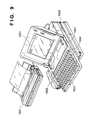
- Fig. 9 is a perspective view of the information processing apparatus in Fig. 8.
- reference numeral 1901 denotes a flat panel display using the above liquid crystal display device, which displays various menus, graphic pattern information, document information, and the like.
- a coordinate input or item designation input operation can be performed on the flat panel display 1901 by pressing the surface of the touch panel 1803 with a finger of the user or the like.
- Reference numeral 1902 denotes a handset used when the apparatus is used as a telephone set.
- a keyboard 1903 is detachably connected to the main body via a cord and is used to perform various document functions and input various data. This keyboard 1903 has various function keys 1904.
- Reference numeral 1905 denotes an insertion port through which a floppy disk is inserted into the external memory unit 1812.
- Reference numeral 1906 denotes an original insertion table on which an original to be read by the image reader unit 1807 is placed. The read original is discharged from the rear portion of the apparatus. In a facsimile receiving operation or the like, received data is printed by an ink-jet printer 1907.
- the above information processing apparatus serves as a personal computer or a word processor
- various kinds of information input through the keyboard unit 1811 are processed by the control unit 1801 in accordance with a predetermined program, and the resultant information is output, as an image, to the printer unit 1806.
- facsimile information input through the transmission/reception unit 1808 via a communication line is subjected to reception processing in the control unit 1801 in accordance with a predetermined program, and the resultant information is outputted, as a received image, to the printer unit 1806.
- an original is read by the image reader unit 1807, and the read original data is output, as an image to be copied, to the printer unit 1806 via the control unit 1801.
- original data read by the image reader unit 1807 is subjected to transmission processing in the control unit 1801 in accordance with a predetermined program, and the resultant data is transmitted to a communication line via the transmission/reception unit 1808.
- the above information processing apparatus may be designed as an integrated apparatus incorporating an ink-jet printer in the main body, as shown in Fig. 10. In this case, the portability of the apparatus can be improved.
- the reference numerals in Fig. 10 denote parts having the same functions as those in Fig. 9.
- Fig. 11 illustrates a coloring method of a color filter, and shows a top view of one of the color filters formed on the substrate in Fig. 1.
- Reference numeral 101 denotes a color filter substrate (corresponding to the substrate 1 in Fig. 4), and 102 denotes a black matrix (corresponding to the black matrix 2 in Fig. 4), formed on the color filter substrate 101 and having a light-shielding characteristic.
- Reference numeral 103 denotes an opening (corresponding to the light-transmitting portion 7 in Fig. 4) provided on the black matrix 102.
- an ink applying layer corresponding to the resin layer 3 in Fig. 4) is formed, which is subjected to coloring with ink.
- the ink applying layer includes a striped water-repellent portion (corresponding to the uncolored portion 5 in Fig 4) between the laterally neighboring openings of the black matrix 102, wherein the striped portion is formed by irradiating ultraviolet ray.
- Reference numeral 104 denotes a coloring portion of the ink applying layer, wherein ink droplets 202 discharged on the ink applying layer are mixed with each other as shown in Fig. 12 and spread to the area 104 shown in Fig. 11.
- Reference numeral 55 denotes an ink-jet head unit for coloring a color filter shown in Fig. 1, which comprises ink-jet heads 55b, 55c and 55d for respective colors (red (R), green (G), and blue (B)).
- the ink-jet heads 55b, 55c and 55d respectively have a plurality of nozzles (not shown) in the longitudinal direction, and are arranged at an angle on a plane which is parallel to the substrate 101 in a way that the nozzle pitch matches the pixel pitch.
- the ink-jet head unit 55 discharges ink while being scanned relatively to the substrate 101 in the direction of arrow A, thereby coloring each pixel array.
- the inventors of the present invention have discovered that, when performing the foregoing coloring with an elongated ink-jet head having a large number (e.g., 1408) of ink discharge nozzles, the amount of ink discharged from the central portion of the ink-jet head decreases as the consecutive coloring operation is repeated.
- Fig. 13 represents the above phenomenon. As coloring operation by scanning is repeated, the color density of the color filter, colored by the central nozzles of the ink-jet head decreases. Note that this experiment employs an ink-jet head 300 (Figs. 14A and 14B) having ink supply openings 306 and 308 at both ends of the ink chamber 304 which is formed in the elongated form so as to correspond to the plurality of ink discharge nozzles 302.
- Fig. 14A shows the state where the ink supply opening 308 provided on the right was closed
- Fig. 14B shows the state where the ink supply opening 306 provided on the left was closed.
- Figs. 15A and 15B are graphs demonstrating the decreasing ink discharge amount in the experiment.
- the ink discharge was performed while maintaining the amount of dissolved oxygen in the ink to 1 ppm or less.
- the experiment employed the aforementioned ink-jet head having ink supply openings at both ends of the ink chamber, wherein the number of nozzles is 1408 and the head length is about 100 mm.
- ink is circulated at low speed from the ink supply opening 306 to the other ink supply opening 308 in the ink chamber 304 during coloring of a color filter so as to force out of the ink chamber 304, the residual micro bubbles or ink with dissolved oxygen partially increased.
- the present embodiment enables stabilizing ink discharge over a long period of time.
- the aforementioned experiment used a method shown in Fig. 19 in which an ink sub tank is arranged at a position higher than the ink-jet head 300 and the height difference is used to supply ink to the ink chamber, and a method shown in Fig. 20 in which ink is supplied by a turbine pump such that the ink does not drip from the nozzle.
- the ink flow rate is about 0.2 - 6 cc/minute, it is preferable to set the flow rate so that the entire ink in the ink chamber 304 is circulated during a single scan of the ink-jet head which performs coloring operation.
- the ink flow rate can be changed by adjusting the height difference between the height of the sub tank and the height of the ink exit opening of the head exiting ink to the main tank.
- the residual ink in the sub tank becomes low, ink is pumped out of the main tank and supplied to the sub tank.
- two forms are possible: arranging a pump on the ink supplying side of the head, or arranging a pump on the ink discharging side.
- an open-type propeller pump is used to prevent excessive force in case the path between the pump and head is clogged, thus avoiding damage.
- the interior of the head becomes an abnormally high positive pressure, ink may leak from the head.
- the interior of the head can always be kept in negative pressure, thus can prevent ink leakage.
- the ink discharge amount does not fluctuate even if coloring operation by scanning is repeatedly performed.
- the ink circulation method according to the present embodiment is particularly effective.
- the ink circulation be performed continuously even when the ink-jet head is not discharging ink.
- the number of recovery operation and the amount of discharge by the ink-jet head are reduced, making it possible to reduce ink waste.
- Fig. 22 is an illustrative view showing a configuration of an ink discharge amount measuring apparatus.
- reference numeral 401 denotes an image processing apparatus which measures density; 402, a personal computer (PC) which controls the image processing apparatus 401 and XY control stage 404; 403, a magnification optical system for magnifying an image; 404, an XY control stage used for consecutively measuring density of a measuring subject; 405, a line sensor camera which picks up an image of a measuring subject and sends it to the image processing apparatus 401; and 406, a light source of a transmissive light provided underneath the XY control stage 404.
- PC personal computer
- the central portion of the stage surface of the XY control stage 404 is made of a glass so that the measuring subject is irradiated by the light source 406 and picked up by the line sensor camera 405. Therefore, the line sensor camera 405 and light source 406 have a fixed positional relation.
- the PC 402 controls the XY control stage 404 through the RS 232C or GPIB (general purpose interface bus), and also controls the image processing apparatus 401.
- Fig. 23 shows a line pattern printed on a glass substrate 410 by utilizing a plurality of different nozzles of the ink-jet head.
- the "same nozzle direction" in Fig. 23 indicates the direction in which line patterns printed respectively by the same nozzle are extended, and the “different nozzle direction” in Fig. 23 indicates the direction in which line patterns printed by different nozzles are arranged. Note that since regular ink discharged on a plain glass substrate is repelled, it is preferable that the glass substrate 410 be subjected to special treatment for receiving ink (in the present embodiment, the glass substrate 410 is coated with polyvinyl alcohol as an ink absorptive composition layer 412).
- ink discharged by each nozzle is uniformly absorbed by the composition layer 412, and a line pattern shown in Fig. 23 is formed.
- the composition layer 412 be as colorless and transparent as possible (which does not absorb transmitted light). Note that it is also possible to make the glass substrate not repel ink by discharging ink containing resin or the like on the glass substrate.
- the magnification optical system 403 focuses on the line pattern shown in Fig. 23, and the image is picked up by the line sensor camera 405 with an appropriate setting of magnification and intensity of the light source 406, and sent to the image processing apparatus 401.
- the line sensor camera 405 picks up monochrome images.
- An image picked up by the line sensor camera 405 is constructed by minimum pixel units which are the units resolvable by the image processing apparatus (in the present embodiment, A/D conversion device having 8 bits is used).
- the minimum pixel unit is constructed so as to be expressed in 256 (0 to 255) levels of luminance in accordance with the intensity of transmitted light at each pixel point.
- density of the line pattern is determined by how much transmitted light is absorbed when the light transmits through the line pattern having a color (density) subjected to measurement. More specifically, when the density of the line pattern subjected to measurement is high, the transmitted light is absorbed and weakened. In other words, the luminance level of minimum pixels within the area of the line pattern which is subjected to measurement declines. On the contrary, when the density of the line pattern is low, the luminance level of minimum pixels within the area of the line pattern which is subjected to measurement increases.
- the present embodiment applies this concept, and uses the absorptivity of transmitted light as density (luminance level is obtained in the actual image processing).
- a frame (hereinafter referred to as a window) shown in Fig. 24 having a fixed size is placed on the line pattern image subjected to measurement, which has been picked up by the line sensor camera as described above.
- the window is constructed with n x m pixels as shown in Fig. 25 (since line sensor camera is used, the image in Fig. 25 is obtained by scanning the line pattern for m pixels in the line pattern's width direction).
- a luminance level of each pixel is obtained (pixel luminance: Qnm).
- the same size of window is placed on the portion where there is no line pattern (the glass portion), and a luminance level of each pixel is obtained (pixel reference luminance Inm).
- Pixel density Dnm Log (pixel reference luminance Inm / pixel luminance Qnm)
- pixel density 0 stands in the pixels around the line pattern where density is low. Even if these are summed, the pixel density for the entire window does not change much. In other words, even if a large window is placed on the line pattern, the obtained density substantially represents the density of the line pattern only. Therefore, the method according to the present embodiment can calculate correct density of the line pattern regardless of the size of the window.
- the line patterns are consecutively read by controlling the XY stage 404 by the PC 402, and then by placing the window, density of all the line patterns can be obtained.
- the amount of ink per single discharge of the nozzle which has printed the line pattern is obtained, with the use of a calibration line which will be described later.
- the density of the line pattern obtained above is the sum of the ink dot density formed by 50 discharges of ink.
- the density of the line pattern is divided by the number of times of ink discharges for forming the line pattern.
- density of the entire line pattern does not have to be obtained, but, for instance, density for half the length (25 discharges) may be obtained.
- the amount of ink per single discharge means the amount of one ink droplet.
- the present embodiment uses the expression "the amount of ink per single discharge" instead of "droplet.”
- the amount of discharge of at least two or more nozzles are obtained by weighting method or absorbance method.
- these at least two or more nozzles have as much difference as possible in the amount of ink per single discharge under a fixed condition.
- the amount of ink per single discharge is obtained by weighting method, for four nozzles having different discharge amounts under a fixed condition.
- ink is discharged in the same condition as the above fixed condition under which the ink discharge amount is obtained. Then, density of a line pattern (or may be ink dots) formed by the discharged ink on the glass substrate 410 is measured by the above-described method. Accordingly, the ink discharge amount of four nozzles can be obtained from the line patterns formed by the four nozzles.
- Fig. 26 is a graph plotting the relation between the amount of ink per single discharge and density of an ink dot formed on the glass substrate 410 with respect to the aforementioned four nozzles.
- black dots indicate the ink discharge amount of four nozzles and their densities.
- the graph shows that the four black dots are substantially on a straight line. Therefore, by drawing a straight line which passes through the four black dots, ink-dot density corresponding to an arbitrary discharge amount can be uniquely obtained. This straight line will be referred to as a calibration line.
- the calibration line is a straight line, a minimum of two dots on the graph are necessary to obtain the calibration line.
- a calibration line can be obtained with the minimum of two nozzles, instead of using four nozzles as described above.
- the present embodiment uses the ink discharge amount data obtained by a weighting method or absorbance method to obtain a calibration line, the precision of each measurement method directly affects the precision of ink discharge amount measurement. Accordingly, it is preferable to obtain a calibration line with the use of three or more nozzles. Also, it is necessary to obtain a calibration line each time the ink to be used is changed.
- Density of a line pattern formed by ink discharge of an arbitrary nozzle under an arbitrary condition is measured by the above-described method, and from the aforementioned calibration line, the ink discharge amount of the nozzle is obtained.
- the above data can be obtained also from an ink-dot pattern.
- ink dot density is measured by obtaining an average density value of 50 dots.
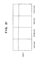
- An ink-dot pattern for density measurement is shown in Fig. 27.
- the above-described frame size is set as shown in Fig. 28.
- Fig. 29 shows an image on which the window is placed. Density detection based on the window can be realized by the method described above.
- the amount of ink per single discharge for each nozzle of the ink-jet head 300 is measured before manufacturing a color filter.
- the ink discharge amount of each nozzle measured at this time is set as a normal value "1".
- the discharge amount of each nozzle is obtained again by the above-described method, and a difference with the normal value measured before manufacturing the color filter is obtained with respect to all the nozzles. Based on a value of 3 ⁇ of the difference, a magnitude of the variation rate of the difference in the discharge amount is determined.
- acceptability of color filters as a result of a sensory inspection of the manufactured color filters is determined in accordance with the variation rate of the discharge amount, and the following results are obtained.
- the sensory inspection is implemented by determining whether or not any defect is recognized by visual inspection.
- the variation rate of the discharge amount is il% or less, no defect is recognized and the acceptability of the color filters as a result of sensory inspection is 100%.
- the acceptability of the color filters as a result of sensory inspection is 70%.
- the variation rate of the discharge amount is larger than ⁇ 2% and equal to or less than ⁇ 3%, the acceptability of the color filters as a result of sensory inspection is 20%.
- the variation rate of the discharge amount is larger than ⁇ 3%, the acceptability of the color filters as a result of sensory inspection is 0%.
- the variation rate of the ink discharge amount per nozzle can be kept within the aforementioned variation rate ⁇ 3% over a long period of time, even if a large number of times of ink discharge operation is repeatedly performed to manufacture a large number of color filters, and high-quality color filters can be manufactured.
- the amount of ink discharged from each nozzle is measured in step S2. Based on the measured ink discharge amount of each nozzle, the discharge pitch for manufacturing a color filter is calculated, and the discharge pitch is set so that the density of discharged lines (pixels of a color filter) formed by respective nozzles is uniform (step S4). In this step, the normal value of the ink discharge amount for each nozzle is specified as described above.
- a color filter is produced at the set pitch (step S6), then density measurement (discharge amount measurement) is performed on the measurement line which is printed periodically or on the pixels of a color filter, and it is determined whether or not the variation rate 3 ⁇ of a difference between the measured discharge amount and the discharge amount measured at the time of determining the discharge pitch for manufacturing a color filter is ⁇ 3% or less as mentioned above (step S8). If it is ⁇ 3% or less, color filter manufacturing is continued. If it is larger than ⁇ 3%, it is determined whether or not a predetermined number or more of color filters have been produced (step S10). If the produced number of color filters is less than the predetermined number, the ink-jet head is regarded as the end of the life cycle and exchanged (step S12).
- a nozzle group which has been used may be regarded as the end of the life cycle and exchanged with a nozzle group which has not been used. If the produced number of color filters is larger than the predetermined number, the process returns to step S4 to set print density again.
- the color filter according to the present embodiment includes both cases of having or not having a color filter on the TFT array side.
- the variation rate of the ink discharge amount per nozzle is specified.
- the present invention may be so set that the colored portion is formed when the variation rate of the ink discharge amount for each pixel, which is the total ink discharge amount (discharge volume) of respective nozzles coloring each pixel, is within a predetermined value, and that the discharge density is set again when the variation rate exceeds the predetermined value.
- a color filter itself may be measured to obtain the discharge amount for each pixel.
- the embodiment described above comprises means (e.g., an electrothermal transducer, laser beam generator, and the like) for generating heat energy as energy utilized upon execution of ink discharge, and adopts a method which causes a change in state of ink by heat energy, among the ink-jet printing method. According to this printing method, a high-density, high-precision printing operation can be attained.
- means e.g., an electrothermal transducer, laser beam generator, and the like
- the system is effective because, by applying at least one driving signal, which corresponds to printing information and gives a rapid temperature rise exceeding film boiling, to each of electrothermal transducers arranged in correspondence with a sheet or liquid channels holding a liquid (ink), heat energy is generated by the electrothermal transducer to effect film boiling on the heat acting surface of the printhead, and consequently, a bubble can be formed in the liquid (ink) in one-to-one correspondence with the driving signal.
- the driving signal is applied as a pulse signal, the growth and shrinkage of the bubble can be attained instantly and adequately to achieve discharge of the liquid (ink) with the particularly high response characteristics.
- the arrangement using U.S. Patent Nos. 4,558,333 and 4,459,600 which disclose the arrangement having a heat acting portion arranged in a flexed region is also included in the present invention.
- the present invention can be effectively applied to an arrangement based on Japanese Patent Laid-Open No. 59-123670 which discloses the arrangement using a slot common to a plurality of electrothermal transducers as a discharge portion of the electrothermal transducers, or Japanese Patent Laid-Open No. 59-138461 which discloses the arrangement having an opening for absorbing a pressure wave of heat energy in correspondence with a discharge portion.
- a full line type printhead having a length corresponding to the width of a maximum printing medium which can be printed by the printer
- either the arrangement which satisfies the full-line length by combining a plurality of printheads as disclosed in the above specification or the arrangement as a single printhead obtained by forming printheads integrally can be used.
- an exchangeable chip type printhead which can be electrically connected to the apparatus main unit and can receive ink from the apparatus main unit upon being mounted on the apparatus main unit, or a cartridge type printhead in which an ink tank is integrally arranged on the printhead itself, is applicable to the present invention.
- recovery means for the printhead, preliminary auxiliary means, and the like provided as an arrangement of the printer of the present invention since the printing operation can be further stabilized.
- examples of such means include, for the printhead, capping means, cleaning means, pressurization or suction means, and preliminary heating means using electrothermal transducers, another heating element, or a combination thereof. It is also effective for stable printing to provide a preliminary discharge mode which performs discharge independently of printing.
- the ink is a liquid.
- the present invention may employ ink which is solid at room temperature or less, or ink which softens or liquefies at room temperature, or ink which liquefies upon application of a printing signal.
- ink which is solid in a non-use state and liquefies upon heating may be used.
- ink which liquefies upon application of heat energy according to a printing signal and is discharged in a liquid state ink which begins to solidify when it reaches a printing medium, or the like, is applicable to the present invention.
- ink may be situated opposite to electrothermal transducers while being held in a liquid or solid state in recess portions of a porous sheet or through holes, as described in Japanese Patent Laid-Open No. 54-56847 or 60-71260.
- the above-mentioned film boiling system is most effective for the above-mentioned ink.
- the present invention is not limited to this, but may utilize a piezoelectric element.
- the present invention by generating an ink flow from the ink supply opening to the ink exiting opening in the ink chamber, variation of the ink discharge amount is suppressed, and thus a color filter with no color unevenness can be manufactured.
Landscapes
- Physics & Mathematics (AREA)
- General Physics & Mathematics (AREA)
- Optics & Photonics (AREA)
- Nonlinear Science (AREA)
- Engineering & Computer Science (AREA)
- Manufacturing & Machinery (AREA)
- Mathematical Physics (AREA)
- Chemical & Material Sciences (AREA)
- Crystallography & Structural Chemistry (AREA)
- Optical Filters (AREA)
- Liquid Crystal (AREA)
Abstract


Description
Claims (61)
- A color filter manufacturing apparatus for forming an array of colored portion of a color filter by discharging a plurality of inks from a plurality of discharge orifices at a predetermined density by using an ink-jet head having a plurality of discharge orifices, an ink chamber connected to the plurality of discharge orifices, an ink supply opening for supplying ink to the ink chamber, and an ink exit opening for exiting ink from the ink chamber, wherein the colored portion is formed when a variation rate of ink volume discharged from the plurality of discharge orifices for forming the array of colored portion is ±3% or less.
- The color filter manufacturing apparatus according to claim 1, wherein the colored portion is formed when a variation rate of ink volume discharged from the plurality of discharge orifices for forming the array of colored portion is ±2% or less after ink discharge has started.
- The color filter manufacturing apparatus according to claim 2, wherein the colored portion is formed when a variation rate of ink volume discharged from the plurality of discharge orifices for forming the array of colored portion is ±1% or less after ink discharge has started.
- The color filter manufacturing apparatus according to claim 1, wherein when the variation rate exceeds ±3% after ink discharge has started, the discharge density is set again.
- The color filter manufacturing apparatus according to claim 1, wherein when the variation rate exceeds ±2% after ink discharge has started, the discharge density is set again.
- The color filter manufacturing apparatus according to claim 1, wherein when the variation rate exceeds ±1% after ink discharge has started, the discharge density is set again.
- The color filter manufacturing apparatus according to any one of claims 1 to 6, wherein the variation rate is calculated based on a result of measured transmissivity of the array of colored portion formed.
- The color filter manufacturing apparatus according to claim 7, wherein a difference in the discharge amount is obtained for all nozzles, the discharge amount obtained based on transmissivity of an array of line pattern or dot pattern, and wherein the variation rate is determined by 3σ of the difference.
- The color filter manufacturing apparatus according to claim 1, comprising ink flow generating means for generating a flow of ink from the ink supply opening to the ink exit opening in the ink chamber while discharging ink from the discharge orifices for coloring.
- The color filter manufacturing apparatus according to claim 9, wherein said ink flow generating means flows ink into the ink chamber by using a height difference between a height of the ink chamber and a height of an ink tank containing ink.
- The color filter manufacturing apparatus according to claim 9, wherein the ink flow generating means comprises a pump for circulating ink.
- The color filter manufacturing apparatus according to claim 11, wherein the pump is provided near the ink exit opening of the ink chamber.
- The color filter manufacturing apparatus according to claim 1, wherein an entire area of one color filter is colored by scanning the ink-jet head plural number of times.
- The color filter manufacturing apparatus according to claim 1, wherein said ink-jet head is a head which discharges ink by utilizing heat energy and comprises a heat energy generator for generating heat energy to be applied to ink.
- A color filter manufacturing method of forming an array of colored portion of a color filter by discharging a plurality of inks from a plurality of discharge orifices at a predetermined density by using an ink-jet head having a plurality of discharge orifices, an ink chamber connected to the plurality of discharge orifices, an ink supply opening for supplying ink to the ink chamber, and an ink exit opening for exiting ink from the ink chamber, wherein the colored portion is formed when a variation rate of ink volume discharged from the plurality of discharge orifices for forming the array of colored portion is ±3% or less.
- The color filter manufacturing method according to claim 15, wherein the colored portion is formed when a variation rate of ink volume discharged from the plurality of discharge orifices for forming the array of colored portion is ±2% or less after ink discharge has started.
- The color filter manufacturing method according to claim 16, wherein the colored portion is formed when a variation rate of ink volume discharged from the plurality of discharge orifices for forming the array of colored portion is ±1% or less after ink discharge has started.
- The color filter manufacturing method according to claim 15, wherein when the variation rate exceeds ±3% after ink discharge has started, the discharge density is set again.
- The color filter manufacturing method according to claim 15, wherein when the variation rate exceeds ±2% after ink discharge has started, the discharge density is set again.
- The color filter manufacturing method according to claim 15, wherein when the variation rate exceeds ±1% after ink discharge has started, the discharge density is set again.
- The color filter manufacturing method according to any one of claims 15 to 20, wherein the variation rate is calculated based on a result of measured transmissivity of the array of colored portion formed.
- The color filter manufacturing method according to claim 21, wherein a difference in the discharge amount is obtained for all nozzles, the discharge amount obtained based on transmissivity of an array of line pattern or dot pattern, and wherein the variation rate is determined by 3σ of the difference.
- The color filter manufacturing method according to claim 15, wherein a flow of ink is generated from the ink supply opening to the ink exit opening in the ink chamber while discharging ink from the discharge orifices for coloring.
- The color filter manufacturing method according to claim 23, wherein the flow of ink is generated by flowing ink into the ink chamber by using a height difference between a height of the ink chamber and a height of an ink tank containing ink.
- The color filter manufacturing method according to claim 23, wherein the flow of ink is generated by a pump for circulating ink.
- The color filter manufacturing method according to claim 25, wherein the pump is provided near the ink exit opening of the ink chamber.
- The color filter manufacturing method according to claim 15, wherein an entire area of one color filter is colored by scanning the ink-jet head plural number of times.
- The color filter manufacturing method according to claim 15, wherein said ink-jet head is a head which discharges ink by utilizing heat energy and comprises a heat energy generator for generating heat energy to be applied to ink.
- A color filter manufactured by forming an array of colored portion of a color filter by discharging a plurality of inks from a plurality of discharge orifices at a predetermined density by using an ink-jet head having a plurality of discharge orifices, an ink chamber connected to the plurality of discharge orifices, an ink supply opening for supplying ink to the ink chamber, and an ink exit opening for exiting ink from the ink chamber, wherein the colored portion is formed when a variation rate of ink volume discharged from the plurality of discharge orifices for forming the array of colored portion is ±3% or less.
- The color filter according to claim 29,
manufactured by forming the colored portion when a variation rate of ink volume discharged from the plurality of discharge orifices for forming the array of colored portion is ±2% or less after ink discharge has started. - The color filter according to claim 29,
manufactured by forming the colored portion when a variation rate of ink volume discharged from the plurality of discharge orifices for forming the array of colored portion is ±1% or less after ink discharge has started. - A display device integrally comprising:wherein the colored portion is formed when a variation rate of ink volume discharged from the plurality of discharge orifices for forming the array of colored portion is ±3% or less.a color filter manufactured by forming an array of colored portion of a color filter by discharging a plurality of inks from a plurality of discharge orifices at a predetermined density by using an ink-jet head having a plurality of discharge orifices, an ink chamber connected to the plurality of discharge orifices, an ink supply opening for supplying ink to the ink chamber, and an ink exit opening for exiting ink from the ink chamber; andlight-amount changing means for enabling to change an amount of light,
- The display device according to claim 32, wherein said color filter is manufactured by forming the colored portion when a variation rate of ink volume discharged from the plurality of discharge orifices for forming the array of colored portion is ±2% or less after ink discharge has started.
- The display device according to claim 32, wherein said color filter is manufactured by forming the colored portion when a variation rate of ink volume discharged from the plurality of discharge orifices for forming the array of colored portion is ±1% or less after ink discharge has started.
- An apparatus comprising a display device integrally having: a color filter manufactured by forming an array of colored portion of a color filter by discharging a plurality of inks from a plurality of discharge orifices at a predetermined density by using an ink-jet head having a plurality of discharge orifices, an ink chamber connected to the plurality of discharge orifices, an ink supply opening for supplying ink to the ink chamber, and an ink exit opening for exiting ink from the ink chamber; and light-amount changing means for enabling to change an amount of light; and
image-signal supplying means for supplying an image signal to the display device,
wherein the colored portion is formed when a variation rate of ink volume discharged from the plurality of discharge orifices for forming the array of colored portion is ±3% or less. - The apparatus comprising a display device according to claim 35, wherein said color filter is manufactured by forming the colored portion when a variation rate of ink volume discharged from the plurality of discharge orifices for forming the array of colored portion is ±2% or less after ink discharge has started.
- The apparatus comprising a display device according to claim 35, wherein said color filter is manufactured by forming the colored portion when a variation rate of ink volume discharged from the plurality of discharge orifices for forming the array of colored portion is ±1% or less after ink discharge has started.
- A color filter manufacturing apparatus for forming an array of colored portion of a color filter by discharging a plurality of inks from a plurality of discharge orifices at a predetermined density by using an ink-jet head having a plurality of discharge orifices, an ink chamber connected to the plurality of discharge orifices, an ink supply opening for supplying ink to the ink chamber, and an ink exit opening for exiting ink from the ink chamber, comprising:
ink flow generating means for generating a flow of ink from the ink supply opening to the ink exit opening in the ink chamber,
wherein said ink flow generating means continuously generates the flow of ink during a period of discharging ink from the orifices for coloring and a period of not discharging ink. - The color filter manufacturing apparatus according to claim 38, wherein said ink flow generating means flows ink into the ink chamber by using a height difference between a height of the ink chamber and a height of an ink tank containing ink.
- The color filter manufacturing apparatus according to claim 38, wherein the ink flow generating means comprises a pump for circulating ink.
- The color filter manufacturing apparatus according to claim 40, wherein the pump is provided near the ink exit opening of the ink chamber.
- The color filter manufacturing apparatus according to claim 38, wherein an entire area of one color filter is colored by scanning the ink-jet head plural number of times.
- The color filter manufacturing apparatus according to claim 38, wherein said ink-jet head is a head which discharges ink by utilizing heat energy and comprises a heat energy generator for generating heat energy to be applied to ink.
- A color filter manufacturing method of forming an array of colored portion of a color filter by discharging a plurality of inks from a plurality of discharge orifices at a predetermined density by using an ink-jet head having a plurality of discharge orifices, an ink chamber connected to the plurality of discharge orifices, an ink supply opening for supplying ink to the ink chamber, and an ink exit opening for exiting ink from the ink chamber,
wherein a flow of ink is continuously generated from the ink supply opening to the ink exit opening in the ink chamber during a period of discharging ink from the orifices for coloring and a period of not discharging ink. - The color filter manufacturing method according to claim 44, wherein the flow of ink is generated by flowing ink into the ink chamber by using a height difference between a height of the ink chamber and a height of an ink tank containing ink.
- The color filter manufacturing method according to claim 44, wherein the flow of ink is generated by a pump for circulating ink.
- The color filter manufacturing method according to claim 46, wherein the pump is provided near the ink exit opening of the ink chamber.
- The color filter manufacturing method according to claim 44, wherein an entire area of one color filter is colored by scanning the ink-jet head plural number of times.
- The color filter manufacturing method according to claim 44, wherein said ink-jet head is a head which discharges ink by utilizing heat energy and comprises a heat energy generator for generating heat energy to be applied to ink.
- A color filter manufactured by forming an array of colored portion of a color filter by discharging a plurality of inks from a plurality of discharge orifices at a predetermined density by using an ink-jet head having a plurality of discharge orifices, an ink chamber connected to the plurality of discharge orifices, an ink supply opening for supplying ink to the ink chamber, and an ink exit opening for exiting ink from the ink chamber, wherein a flow of ink is generated from the ink supply opening to the ink exit opening in the ink chamber during a period of discharging ink from the orifices for coloring and a period of not discharging ink.
- A display device integrally comprising:wherein a flow of ink is generated from the ink supply opening to the ink exit opening in the ink chamber during a period of discharging ink from the orifices for coloring and a period of not discharging ink.a color filter manufactured by forming an array of colored portion of a color filter by discharging a plurality of inks from a plurality of discharge orifices at a predetermined density by using an ink-jet head having a plurality of discharge orifices, an ink chamber connected to the plurality of discharge orifices, an ink supply opening for supplying ink to the ink chamber, and an ink exit opening for exiting ink from the ink chamber; andlight-amount changing means for enabling to change an amount of light,
- An apparatus comprising a display device integrally having: a color filter manufactured by forming an array of colored portion of a color filter by discharging a plurality of inks from a plurality of discharge orifices at a predetermined density by using an ink-jet head having a plurality of discharge orifices, an ink chamber connected to the plurality of discharge orifices, an ink supply opening for supplying ink to the ink chamber, and an ink exit opening for exiting ink from the ink chamber; and light-amount changing means for enabling to change an amount of light; and
image-signal supplying means for supplying an image signal to the display device,
wherein a flow of ink is generated from the ink supply opening to the ink exit opening in the ink chamber during a period of discharging ink from the orifices for coloring and a period of not discharging ink. - A method of reducing unevenness of discharge volume in a plurality of discharge nozzles by ink circulation, in a case of forming an array of colored portion of a color filter by discharging a plurality of inks from a plurality of discharge orifices at a predetermined density by using an ink-jet head having a plurality of discharge orifices, an ink chamber connected to the plurality of discharge orifices, an ink supply opening for supplying ink to the ink chamber, and an ink exit opening for exiting ink from the ink chamber,
wherein a flow of ink is generated from the ink supply opening to the ink exit opening in the ink chamber while ink is discharged from the orifices for coloring, and the colored portion is formed when a variation rate of ink volume discharged from the plurality of discharge orifices for forming the array of colored portion is ±3% or less. - The method of reducing unevenness of discharge volume in a plurality of discharge nozzles by ink circulation according to claim 53, wherein the colored portion is formed when a variation rate of ink volume discharged from the plurality of discharge orifices for forming the array of colored portion is ±2% or less after ink discharge has started.
- The method of reducing unevenness of discharge volume in a plurality of discharge nozzles by ink circulation according to claim 54, wherein the colored portion is formed when a variation rate of ink volume discharged from the plurality of discharge orifices for forming the array of colored portion is ±1% or less after ink discharge has started.
- The method of reducing unevenness of discharge volume in a plurality of discharge nozzles by ink circulation according to claim 53, wherein when the variation rate exceeds ±3% after ink discharge has started, the discharge density is set again.
- The method of reducing unevenness of discharge volume in a plurality of discharge nozzles by ink circulation according to claim 53, wherein when the variation rate exceeds ±2% after ink discharge has started, the discharge density is set again.
- The method of reducing unevenness of discharge volume in a plurality of discharge nozzles by ink circulation according to claim 53, wherein when the variation rate exceeds ±1% after ink discharge has started, the discharge density is set again.
- A method of reducing unevenness of discharge volume in a plurality of discharge nozzles by ink circulation, in a case of forming an array of colored portion of a color filter by discharging a plurality of inks from a plurality of discharge orifices at a predetermined density by using an ink-jet head having a plurality of discharge orifices, an ink chamber connected to the plurality of discharge orifices, an ink supply opening for supplying ink to the ink chamber, and an ink exit opening for exiting ink from the ink chamber,
wherein a flow of ink is generated from the ink supply opening to the ink exit opening in the ink chamber during a period of discharging ink from the orifices for coloring and a period of not discharging ink. - A method of manufacturing a color filter, which method comprises using an ink jet head having a plurality of ink discharge outlets to discharge ink onto a color filter substrate to form the color filter, wherein the variation in ink discharge volume is ±3% or less.
- A method of manufacturing a color filter, which method comprises using an ink jet head to discharge ink onto a color filter substrate to form the color filter, wherein a flow or circulation of ink is maintained or generated in an ink supply chamber for supplying ink to a discharge outlet of the ink jet head.
Applications Claiming Priority (4)
| Application Number | Priority Date | Filing Date | Title |
|---|---|---|---|
| JP33641598 | 1998-11-27 | ||
| JP33641598 | 1998-11-27 | ||
| JP30753099 | 1999-10-28 | ||
| JP30753099A JP4065476B2 (en) | 1998-11-27 | 1999-10-28 | Color filter manufacturing method and display device manufacturing method |
Publications (2)
| Publication Number | Publication Date |
|---|---|
| EP1004902A2 true EP1004902A2 (en) | 2000-05-31 |
| EP1004902A3 EP1004902A3 (en) | 2001-10-31 |
Family
ID=26565149
Family Applications (1)
| Application Number | Title | Priority Date | Filing Date |
|---|---|---|---|
| EP99309453A Withdrawn EP1004902A3 (en) | 1998-11-27 | 1999-11-26 | Color filter manufacturing method and apparatus, color filter, and display device |
Country Status (5)
| Country | Link |
|---|---|
| US (1) | US6540346B1 (en) |
| EP (1) | EP1004902A3 (en) |
| JP (1) | JP4065476B2 (en) |
| KR (1) | KR100338616B1 (en) |
| TW (1) | TW494064B (en) |
Cited By (2)
| Publication number | Priority date | Publication date | Assignee | Title |
|---|---|---|---|---|
| EP1818179A3 (en) * | 2006-02-10 | 2008-06-25 | Samsung Electronics Co., Ltd. | Nozzle control device and method |
| CN101734012B (en) * | 2008-11-21 | 2014-01-15 | 精工爱普生株式会社 | Method for evaluating discharge amount of liquid droplet discharging device |
Families Citing this family (10)
| Publication number | Priority date | Publication date | Assignee | Title |
|---|---|---|---|---|
| US6733113B2 (en) * | 2001-03-30 | 2004-05-11 | Konica Corporation | Ink-jet recording method and ink-jet recording apparatus |
| JP4141674B2 (en) * | 2001-10-22 | 2008-08-27 | セイコーエプソン株式会社 | Droplet discharge head, wiping method thereof, and electronic apparatus equipped with the same |
| JP2004196936A (en) * | 2002-12-18 | 2004-07-15 | Konica Minolta Holdings Inc | Ink-jet ink and printing method |
| JP4100354B2 (en) * | 2004-02-19 | 2008-06-11 | セイコーエプソン株式会社 | A material coating method, a color filter manufacturing method, an electroluminescence display device manufacturing method, and a plasma display device manufacturing method. |
| DE102005042010A1 (en) * | 2005-09-02 | 2007-03-22 | Siemens Ag | Generator device for independent charging of at least two batteries |
| WO2012030385A1 (en) | 2010-08-30 | 2012-03-08 | Anajet, Inc. | Inkjet printer ink delivery system |
| TWI775523B (en) * | 2014-09-02 | 2022-08-21 | 美商凱特伊夫公司 | Method and system for measuring a parameter |
| JP7301584B2 (en) | 2019-04-15 | 2023-07-03 | キヤノン株式会社 | Image processing device, image processing method, and program |
| JP7271282B2 (en) | 2019-04-15 | 2023-05-11 | キヤノン株式会社 | INKJET RECORDING DEVICE, CONTROL METHOD, AND PROGRAM |
| JP7309427B2 (en) | 2019-04-15 | 2023-07-18 | キヤノン株式会社 | Inkjet recording device, recording method, and program |
Family Cites Families (33)
| Publication number | Priority date | Publication date | Assignee | Title |
|---|---|---|---|---|
| CA1127227A (en) | 1977-10-03 | 1982-07-06 | Ichiro Endo | Liquid jet recording process and apparatus therefor |
| JPS5936879B2 (en) | 1977-10-14 | 1984-09-06 | キヤノン株式会社 | Thermal transfer recording medium |
| US4330787A (en) | 1978-10-31 | 1982-05-18 | Canon Kabushiki Kaisha | Liquid jet recording device |
| US4345262A (en) | 1979-02-19 | 1982-08-17 | Canon Kabushiki Kaisha | Ink jet recording method |
| US4463359A (en) | 1979-04-02 | 1984-07-31 | Canon Kabushiki Kaisha | Droplet generating method and apparatus thereof |
| US4313124A (en) | 1979-05-18 | 1982-01-26 | Canon Kabushiki Kaisha | Liquid jet recording process and liquid jet recording head |
| US4558333A (en) | 1981-07-09 | 1985-12-10 | Canon Kabushiki Kaisha | Liquid jet recording head |
| JPS5975205A (en) | 1982-10-25 | 1984-04-27 | Seiko Epson Corp | Color filter manufacturing method |
| JPS59123670A (en) | 1982-12-28 | 1984-07-17 | Canon Inc | Ink jet head |
| JPS59138461A (en) | 1983-01-28 | 1984-08-08 | Canon Inc | liquid jet recording device |
| JPS6071260A (en) | 1983-09-28 | 1985-04-23 | Erumu:Kk | Recorder |
| JP2607274B2 (en) * | 1988-06-21 | 1997-05-07 | キヤノン株式会社 | Inkjet recording head |
| US5140429A (en) | 1988-06-23 | 1992-08-18 | Canon Kabushiki Kaisha | Ink-jet recording apparatus with mechanism for automatically regulating a recording head |
| JPH0315557A (en) | 1989-03-31 | 1991-01-23 | Canon Inc | inkjet recording device |
| JP2804513B2 (en) | 1989-06-02 | 1998-09-30 | キヤノン株式会社 | Ink jet recording device |
| EP0663296B1 (en) * | 1990-05-11 | 2002-04-03 | Canon Kabushiki Kaisha | Recording apparatus with test pattern reader |
| US5771052A (en) | 1994-03-21 | 1998-06-23 | Spectra, Inc. | Single pass ink jet printer with offset ink jet modules |
| JP2839133B2 (en) | 1994-03-31 | 1998-12-16 | キヤノン株式会社 | Method and apparatus for manufacturing color filter, method for manufacturing liquid crystal display, and method for manufacturing apparatus equipped with liquid crystal display |
| JP3014923B2 (en) * | 1994-06-24 | 2000-02-28 | キヤノン株式会社 | Color filter, method of manufacturing the same, and liquid crystal display using the filter |
| JP3111024B2 (en) | 1995-07-19 | 2000-11-20 | キヤノン株式会社 | Apparatus and method for manufacturing color filter, method for manufacturing display apparatus, and method for manufacturing apparatus provided with display apparatus |
| JP3159919B2 (en) | 1995-08-01 | 2001-04-23 | キヤノン株式会社 | Apparatus and method for manufacturing color filter and method for reducing uneven coloring |
| JP2967052B2 (en) | 1995-09-08 | 1999-10-25 | キヤノン株式会社 | Method and apparatus for manufacturing color filter |
| JP3242830B2 (en) * | 1996-02-29 | 2001-12-25 | 株式会社山武 | Color filter density measurement method |
| JPH1034899A (en) | 1996-07-19 | 1998-02-10 | Canon Inc | Inkjet printing equipment |
| JP2826527B2 (en) | 1996-08-28 | 1998-11-18 | 新潟日本電気株式会社 | Electrostatic inkjet recording device |
| US6158844A (en) | 1996-09-13 | 2000-12-12 | Kabushiki Kaisha Toshiba | Ink-jet recording system using electrostatic force to expel ink |
| JP3288243B2 (en) | 1997-03-06 | 2002-06-04 | 株式会社東芝 | Ink jet recording device |
| JP2978459B2 (en) | 1996-09-30 | 1999-11-15 | キヤノン株式会社 | Method and apparatus for manufacturing color filter, color filter, display apparatus, and apparatus having display apparatus |
| JPH10138515A (en) | 1996-11-07 | 1998-05-26 | Canon Inc | Ink jet recording device |
| US5818485A (en) * | 1996-11-22 | 1998-10-06 | Xerox Corporation | Thermal ink jet printing system with continuous ink circulation through a printhead |
| JP2834106B2 (en) | 1996-11-28 | 1998-12-09 | 新潟日本電気株式会社 | Ink jet recording device |
| US6172693B1 (en) | 1996-11-26 | 2001-01-09 | Nec Corporation | Ink jet recording head having ink stirring electrodes for dispersing ink |
| JP3106110B2 (en) | 1997-03-17 | 2000-11-06 | キヤノン株式会社 | Method and apparatus for manufacturing color filter and method for manufacturing display device |
-
1999
- 1999-10-28 JP JP30753099A patent/JP4065476B2/en not_active Expired - Fee Related
- 1999-11-09 TW TW088119595A patent/TW494064B/en not_active IP Right Cessation
- 1999-11-17 US US09/441,878 patent/US6540346B1/en not_active Expired - Lifetime
- 1999-11-26 KR KR1019990052901A patent/KR100338616B1/en not_active Expired - Fee Related
- 1999-11-26 EP EP99309453A patent/EP1004902A3/en not_active Withdrawn
Cited By (2)
| Publication number | Priority date | Publication date | Assignee | Title |
|---|---|---|---|---|
| EP1818179A3 (en) * | 2006-02-10 | 2008-06-25 | Samsung Electronics Co., Ltd. | Nozzle control device and method |
| CN101734012B (en) * | 2008-11-21 | 2014-01-15 | 精工爱普生株式会社 | Method for evaluating discharge amount of liquid droplet discharging device |
Also Published As
| Publication number | Publication date |
|---|---|
| KR100338616B1 (en) | 2002-05-27 |
| JP4065476B2 (en) | 2008-03-26 |
| JP2000221320A (en) | 2000-08-11 |
| KR20000035717A (en) | 2000-06-26 |
| EP1004902A3 (en) | 2001-10-31 |
| US6540346B1 (en) | 2003-04-01 |
| TW494064B (en) | 2002-07-11 |
Similar Documents
| Publication | Publication Date | Title |
|---|---|---|
| KR100477500B1 (en) | Method for manufacturing color filter, color filter, display device, and device including said display device | |
| JP3697131B2 (en) | Manufacturing method of color filter, manufacturing apparatus, manufacturing method of display device including color filter, and manufacturing method of device including the display device | |
| JP3159919B2 (en) | Apparatus and method for manufacturing color filter and method for reducing uneven coloring | |
| US20020109741A1 (en) | Ink-jet print method and apparatus, color filter, display device, and apparatus having display device | |
| JP2941247B2 (en) | Method for setting ink ejection density, method for manufacturing color filter, method for manufacturing display device, and method for manufacturing device equipped with display device | |
| US6158858A (en) | Method and apparatus for manufacturing color filter, color filter, display device, and apparatus having the display device | |
| JP2001228320A (en) | Method and apparatus for manufacturing color filter | |
| US6109727A (en) | Ink-jet printer and printing method, auxiliary member, ink-jet head, warp correction method, ink-jet head unit and color-mixture reducing method | |
| JP3332854B2 (en) | Manufacturing method of color filter | |
| US6540346B1 (en) | Color filter manufacturing apparatus and method, color filter, display device, apparatus having the display device, and method of reducing unevenness of discharge volume in plural nozzles by ink circulation | |
| EP0791841B1 (en) | Color filter manufacturing apparatus and method | |
| US6386700B1 (en) | Color-filter manufacturing method, color filter, display device, and apparatus having the display device | |
| JP2000284113A (en) | Method for manufacturing color filter, color filter, display device, and device equipped with this display device | |
| JPH112711A (en) | Method for manufacturing color filter, color filter, display device, and device equipped with this display device | |
| JPH1114820A (en) | Method and apparatus for manufacturing color filter, color filter, display device, and device equipped with this display device | |
| JP4282080B2 (en) | Manufacturing method of color filter, manufacturing method of liquid crystal display panel, and manufacturing method of information processing apparatus | |
| JP3880606B2 (en) | Manufacturing method of color filter, manufacturing method of display panel, manufacturing method of information processing device including display panel, manufacturing method of liquid crystal display panel, manufacturing method of information processing device including liquid crystal display panel | |
| JP3814629B2 (en) | Manufacturing method of color filter, manufacturing method of display panel, manufacturing method of information processing device including display panel, manufacturing method of liquid crystal display panel, manufacturing method of information processing device including liquid crystal display panel | |
| JPH10278314A (en) | Method for manufacturing color filter, color filter, display device, and device equipped with this display device |
Legal Events
| Date | Code | Title | Description |
|---|---|---|---|
| PUAI | Public reference made under article 153(3) epc to a published international application that has entered the european phase |
Free format text: ORIGINAL CODE: 0009012 |
|
| AK | Designated contracting states |
Kind code of ref document: A2 Designated state(s): AT BE CH CY DE DK ES FI FR GB GR IE IT LI LU MC NL PT SE Kind code of ref document: A2 Designated state(s): DE ES FR GB IT NL |
|
| AX | Request for extension of the european patent |
Free format text: AL;LT;LV;MK;RO;SI |
|
| PUAL | Search report despatched |
Free format text: ORIGINAL CODE: 0009013 |
|
| AK | Designated contracting states |
Kind code of ref document: A3 Designated state(s): AT BE CH CY DE DK ES FI FR GB GR IE IT LI LU MC NL PT SE |
|
| AX | Request for extension of the european patent |
Free format text: AL;LT;LV;MK;RO;SI |
|
| RIC1 | Information provided on ipc code assigned before grant |
Free format text: 7G 02B 5/20 A, 7G 02F 1/1335 B, 7B 41J 2/00 B |
|
| 17P | Request for examination filed |
Effective date: 20020315 |
|
| AKX | Designation fees paid |
Free format text: DE ES FR GB IT NL |
|
| 17Q | First examination report despatched |
Effective date: 20020611 |
|
| STAA | Information on the status of an ep patent application or granted ep patent |
Free format text: STATUS: THE APPLICATION IS DEEMED TO BE WITHDRAWN |
|
| 18D | Application deemed to be withdrawn |
Effective date: 20021022 |