JP4060790B2 - Modular offshore structure - Google Patents
Modular offshore structure Download PDFInfo
- Publication number
- JP4060790B2 JP4060790B2 JP2003508785A JP2003508785A JP4060790B2 JP 4060790 B2 JP4060790 B2 JP 4060790B2 JP 2003508785 A JP2003508785 A JP 2003508785A JP 2003508785 A JP2003508785 A JP 2003508785A JP 4060790 B2 JP4060790 B2 JP 4060790B2
- Authority
- JP
- Japan
- Prior art keywords
- module
- along
- diagonal
- rdb
- parallelepiped
- Prior art date
- Legal status (The legal status is an assumption and is not a legal conclusion. Google has not performed a legal analysis and makes no representation as to the accuracy of the status listed.)
- Expired - Fee Related
Links
- 230000003014 reinforcing effect Effects 0.000 claims abstract description 19
- 238000000034 method Methods 0.000 claims description 26
- 238000000465 moulding Methods 0.000 claims description 24
- 238000009415 formwork Methods 0.000 claims description 18
- 238000007667 floating Methods 0.000 claims description 17
- 239000012530 fluid Substances 0.000 claims description 9
- 238000004519 manufacturing process Methods 0.000 claims description 8
- 238000005304 joining Methods 0.000 claims description 3
- 238000007789 sealing Methods 0.000 claims description 3
- 238000004026 adhesive bonding Methods 0.000 claims description 2
- 230000002093 peripheral effect Effects 0.000 claims description 2
- 238000000605 extraction Methods 0.000 claims 2
- 230000008878 coupling Effects 0.000 claims 1
- 238000010168 coupling process Methods 0.000 claims 1
- 238000005859 coupling reaction Methods 0.000 claims 1
- 238000010112 shell-mould casting Methods 0.000 claims 1
- XLYOFNOQVPJJNP-UHFFFAOYSA-N water Substances O XLYOFNOQVPJJNP-UHFFFAOYSA-N 0.000 abstract description 13
- 230000001815 facial effect Effects 0.000 abstract 1
- 239000004567 concrete Substances 0.000 description 18
- 239000000463 material Substances 0.000 description 13
- 229910000831 Steel Inorganic materials 0.000 description 12
- 239000010959 steel Substances 0.000 description 12
- 230000009977 dual effect Effects 0.000 description 8
- 238000010276 construction Methods 0.000 description 7
- 239000011440 grout Substances 0.000 description 7
- 238000010586 diagram Methods 0.000 description 5
- 230000002787 reinforcement Effects 0.000 description 5
- 230000007547 defect Effects 0.000 description 4
- 239000013535 sea water Substances 0.000 description 4
- 229920002430 Fibre-reinforced plastic Polymers 0.000 description 3
- 239000011151 fibre-reinforced plastic Substances 0.000 description 3
- 239000011796 hollow space material Substances 0.000 description 3
- 238000002347 injection Methods 0.000 description 3
- 239000007924 injection Substances 0.000 description 3
- 238000009434 installation Methods 0.000 description 3
- 239000011150 reinforced concrete Substances 0.000 description 3
- 238000003860 storage Methods 0.000 description 3
- 230000006378 damage Effects 0.000 description 2
- 239000000835 fiber Substances 0.000 description 2
- 238000005339 levitation Methods 0.000 description 2
- 239000004570 mortar (masonry) Substances 0.000 description 2
- 239000004576 sand Substances 0.000 description 2
- PCTMTFRHKVHKIS-BMFZQQSSSA-N (1s,3r,4e,6e,8e,10e,12e,14e,16e,18s,19r,20r,21s,25r,27r,30r,31r,33s,35r,37s,38r)-3-[(2r,3s,4s,5s,6r)-4-amino-3,5-dihydroxy-6-methyloxan-2-yl]oxy-19,25,27,30,31,33,35,37-octahydroxy-18,20,21-trimethyl-23-oxo-22,39-dioxabicyclo[33.3.1]nonatriaconta-4,6,8,10 Chemical compound C1C=C2C[C@@H](OS(O)(=O)=O)CC[C@]2(C)[C@@H]2[C@@H]1[C@@H]1CC[C@H]([C@H](C)CCCC(C)C)[C@@]1(C)CC2.O[C@H]1[C@@H](N)[C@H](O)[C@@H](C)O[C@H]1O[C@H]1/C=C/C=C/C=C/C=C/C=C/C=C/C=C/[C@H](C)[C@@H](O)[C@@H](C)[C@H](C)OC(=O)C[C@H](O)C[C@H](O)CC[C@@H](O)[C@H](O)C[C@H](O)C[C@](O)(C[C@H](O)[C@H]2C(O)=O)O[C@H]2C1 PCTMTFRHKVHKIS-BMFZQQSSSA-N 0.000 description 1
- 229920000049 Carbon (fiber) Polymers 0.000 description 1
- 229910001294 Reinforcing steel Inorganic materials 0.000 description 1
- 239000000853 adhesive Substances 0.000 description 1
- 230000001070 adhesive effect Effects 0.000 description 1
- 239000002956 ash Substances 0.000 description 1
- 238000005452 bending Methods 0.000 description 1
- 229910052799 carbon Inorganic materials 0.000 description 1
- 239000004917 carbon fiber Substances 0.000 description 1
- 238000004891 communication Methods 0.000 description 1
- 239000000470 constituent Substances 0.000 description 1
- 238000007796 conventional method Methods 0.000 description 1
- 239000010779 crude oil Substances 0.000 description 1
- 238000005520 cutting process Methods 0.000 description 1
- 230000002950 deficient Effects 0.000 description 1
- 238000005553 drilling Methods 0.000 description 1
- 239000003651 drinking water Substances 0.000 description 1
- 235000020188 drinking water Nutrition 0.000 description 1
- 230000002349 favourable effect Effects 0.000 description 1
- 230000009969 flowable effect Effects 0.000 description 1
- 239000010881 fly ash Substances 0.000 description 1
- 239000006261 foam material Substances 0.000 description 1
- 239000000446 fuel Substances 0.000 description 1
- 239000003365 glass fiber Substances 0.000 description 1
- 239000003292 glue Substances 0.000 description 1
- 239000011372 high-strength concrete Substances 0.000 description 1
- 230000003993 interaction Effects 0.000 description 1
- 238000011089 mechanical engineering Methods 0.000 description 1
- 239000004033 plastic Substances 0.000 description 1
- 229920003023 plastic Polymers 0.000 description 1
- 239000002986 polymer concrete Substances 0.000 description 1
- 239000011513 prestressed concrete Substances 0.000 description 1
- 239000012783 reinforcing fiber Substances 0.000 description 1
- 239000010865 sewage Substances 0.000 description 1
- 239000002689 soil Substances 0.000 description 1
- 230000003068 static effect Effects 0.000 description 1
- 238000003466 welding Methods 0.000 description 1
Images


Classifications
-
- E—FIXED CONSTRUCTIONS
- E02—HYDRAULIC ENGINEERING; FOUNDATIONS; SOIL SHIFTING
- E02B—HYDRAULIC ENGINEERING
- E02B3/00—Engineering works in connection with control or use of streams, rivers, coasts, or other marine sites; Sealings or joints for engineering works in general
- E02B3/04—Structures or apparatus for, or methods of, protecting banks, coasts, or harbours
- E02B3/12—Revetment of banks, dams, watercourses, or the like, e.g. the sea-floor
- E02B3/129—Polyhedrons, tetrapods or similar bodies, whether or not threaded on strings
-
- B—PERFORMING OPERATIONS; TRANSPORTING
- B28—WORKING CEMENT, CLAY, OR STONE
- B28B—SHAPING CLAY OR OTHER CERAMIC COMPOSITIONS; SHAPING SLAG; SHAPING MIXTURES CONTAINING CEMENTITIOUS MATERIAL, e.g. PLASTER
- B28B7/00—Moulds; Cores; Mandrels
- B28B7/0029—Moulds or moulding surfaces not covered by B28B7/0058 - B28B7/36 and B28B7/40 - B28B7/465, e.g. moulds assembled from several parts
- B28B7/0035—Moulds characterised by the way in which the sidewalls of the mould and the moulded article move with respect to each other during demoulding
- B28B7/0044—Moulds characterised by the way in which the sidewalls of the mould and the moulded article move with respect to each other during demoulding the sidewalls of the mould being only tilted away from the sidewalls of the moulded article, e.g. moulds with hingedly mounted sidewalls
-
- B—PERFORMING OPERATIONS; TRANSPORTING
- B28—WORKING CEMENT, CLAY, OR STONE
- B28B—SHAPING CLAY OR OTHER CERAMIC COMPOSITIONS; SHAPING SLAG; SHAPING MIXTURES CONTAINING CEMENTITIOUS MATERIAL, e.g. PLASTER
- B28B7/00—Moulds; Cores; Mandrels
- B28B7/16—Moulds for making shaped articles with cavities or holes open to the surface, e.g. with blind holes
- B28B7/18—Moulds for making shaped articles with cavities or holes open to the surface, e.g. with blind holes the holes passing completely through the article
- B28B7/183—Moulds for making shaped articles with cavities or holes open to the surface, e.g. with blind holes the holes passing completely through the article for building blocks or similar block-shaped objects
-
- E—FIXED CONSTRUCTIONS
- E02—HYDRAULIC ENGINEERING; FOUNDATIONS; SOIL SHIFTING
- E02B—HYDRAULIC ENGINEERING
- E02B17/00—Artificial islands mounted on piles or like supports, e.g. platforms on raisable legs or offshore constructions; Construction methods therefor
- E02B17/02—Artificial islands mounted on piles or like supports, e.g. platforms on raisable legs or offshore constructions; Construction methods therefor placed by lowering the supporting construction to the bottom, e.g. with subsequent fixing thereto
- E02B17/025—Reinforced concrete structures
-
- E—FIXED CONSTRUCTIONS
- E02—HYDRAULIC ENGINEERING; FOUNDATIONS; SOIL SHIFTING
- E02B—HYDRAULIC ENGINEERING
- E02B3/00—Engineering works in connection with control or use of streams, rivers, coasts, or other marine sites; Sealings or joints for engineering works in general
- E02B3/04—Structures or apparatus for, or methods of, protecting banks, coasts, or harbours
- E02B3/06—Moles; Piers; Quays; Quay walls; Groynes; Breakwaters ; Wave dissipating walls; Quay equipment
-
- E—FIXED CONSTRUCTIONS
- E04—BUILDING
- E04B—GENERAL BUILDING CONSTRUCTIONS; WALLS, e.g. PARTITIONS; ROOFS; FLOORS; CEILINGS; INSULATION OR OTHER PROTECTION OF BUILDINGS
- E04B1/00—Constructions in general; Structures which are not restricted either to walls, e.g. partitions, or floors or ceilings or roofs
- E04B1/18—Structures comprising elongated load-supporting parts, e.g. columns, girders, skeletons
- E04B1/19—Three-dimensional framework structures
-
- B—PERFORMING OPERATIONS; TRANSPORTING
- B63—SHIPS OR OTHER WATERBORNE VESSELS; RELATED EQUIPMENT
- B63B—SHIPS OR OTHER WATERBORNE VESSELS; EQUIPMENT FOR SHIPPING
- B63B2231/00—Material used for some parts or elements, or for particular purposes
- B63B2231/60—Concretes
- B63B2231/64—Reinforced or armoured concretes
-
- B—PERFORMING OPERATIONS; TRANSPORTING
- B63—SHIPS OR OTHER WATERBORNE VESSELS; RELATED EQUIPMENT
- B63B—SHIPS OR OTHER WATERBORNE VESSELS; EQUIPMENT FOR SHIPPING
- B63B5/00—Hulls characterised by their construction of non-metallic material
- B63B5/14—Hulls characterised by their construction of non-metallic material made predominantly of concrete, e.g. reinforced
- B63B5/18—Hulls characterised by their construction of non-metallic material made predominantly of concrete, e.g. reinforced built-up from elements
-
- E—FIXED CONSTRUCTIONS
- E04—BUILDING
- E04B—GENERAL BUILDING CONSTRUCTIONS; WALLS, e.g. PARTITIONS; ROOFS; FLOORS; CEILINGS; INSULATION OR OTHER PROTECTION OF BUILDINGS
- E04B1/00—Constructions in general; Structures which are not restricted either to walls, e.g. partitions, or floors or ceilings or roofs
- E04B1/18—Structures comprising elongated load-supporting parts, e.g. columns, girders, skeletons
- E04B1/19—Three-dimensional framework structures
- E04B2001/1924—Struts specially adapted therefor
- E04B2001/1927—Struts specially adapted therefor of essentially circular cross section
-
- E—FIXED CONSTRUCTIONS
- E04—BUILDING
- E04B—GENERAL BUILDING CONSTRUCTIONS; WALLS, e.g. PARTITIONS; ROOFS; FLOORS; CEILINGS; INSULATION OR OTHER PROTECTION OF BUILDINGS
- E04B1/00—Constructions in general; Structures which are not restricted either to walls, e.g. partitions, or floors or ceilings or roofs
- E04B1/18—Structures comprising elongated load-supporting parts, e.g. columns, girders, skeletons
- E04B1/19—Three-dimensional framework structures
- E04B2001/1957—Details of connections between nodes and struts
- E04B2001/1972—Welded or glued connection
-
- E—FIXED CONSTRUCTIONS
- E04—BUILDING
- E04B—GENERAL BUILDING CONSTRUCTIONS; WALLS, e.g. PARTITIONS; ROOFS; FLOORS; CEILINGS; INSULATION OR OTHER PROTECTION OF BUILDINGS
- E04B1/00—Constructions in general; Structures which are not restricted either to walls, e.g. partitions, or floors or ceilings or roofs
- E04B1/18—Structures comprising elongated load-supporting parts, e.g. columns, girders, skeletons
- E04B1/19—Three-dimensional framework structures
- E04B2001/1978—Frameworks assembled from preformed subframes, e.g. pyramids
-
- E—FIXED CONSTRUCTIONS
- E04—BUILDING
- E04B—GENERAL BUILDING CONSTRUCTIONS; WALLS, e.g. PARTITIONS; ROOFS; FLOORS; CEILINGS; INSULATION OR OTHER PROTECTION OF BUILDINGS
- E04B1/00—Constructions in general; Structures which are not restricted either to walls, e.g. partitions, or floors or ceilings or roofs
- E04B1/18—Structures comprising elongated load-supporting parts, e.g. columns, girders, skeletons
- E04B1/19—Three-dimensional framework structures
- E04B2001/1981—Three-dimensional framework structures characterised by the grid type of the outer planes of the framework
- E04B2001/1984—Three-dimensional framework structures characterised by the grid type of the outer planes of the framework rectangular, e.g. square, grid
-
- Y—GENERAL TAGGING OF NEW TECHNOLOGICAL DEVELOPMENTS; GENERAL TAGGING OF CROSS-SECTIONAL TECHNOLOGIES SPANNING OVER SEVERAL SECTIONS OF THE IPC; TECHNICAL SUBJECTS COVERED BY FORMER USPC CROSS-REFERENCE ART COLLECTIONS [XRACs] AND DIGESTS
- Y10—TECHNICAL SUBJECTS COVERED BY FORMER USPC
- Y10S—TECHNICAL SUBJECTS COVERED BY FORMER USPC CROSS-REFERENCE ART COLLECTIONS [XRACs] AND DIGESTS
- Y10S52/00—Static structures, e.g. buildings
- Y10S52/10—Polyhedron
Abstract
Description
【技術分野】
【0001】
本発明は、組立式モジュールから陸上および海上で大規模な構造体および基盤構造体を構築する方法および手段に関する。
【背景技術】
【0002】
海上および海岸に建設する際の1つの好ましい方法は、プレキャスト式(組立式)鉄骨鉄筋コンクリート要素を組み立てることである。これらの要素を浮遊させることも好ましい。浮コンクリート構造体の利点は、使用材料の経済性(コンクリートは海上環境に非常によく適する)、工事段階での曳航に加えて、恒久的に浮かべておくためにコンクリート構造体を浮遊させることが容易でありながら、それらは恒久的な設備として十分に重厚である点、そしてそれらは貯蔵空間ともなり得る点にある。コンクリート構造体は、便利で安全な場所で建造し、次いで設置現場まで浮遊させることができる。このような方法は、建設現場のために高価な陸上を占有するのを回避する利点によって用いられる。たとえ設置現場が天候に大きく左右されても、好条件の短い時間帯に迅速に設置することが可能である。
【0003】
浮揚性および非浮揚性コンクリート構造体の応用例の範囲は極めて広範で、
原油の探査、掘削、および生産足場、LPG基地;
艀、船舶およびヨット用浮ドック;
浮いているかまたは大洋底上に基礎をおく、人工島、空港、発電所、工業プラント、ホテル、ショッピング・センタ、橋、半潜水式トンネル、灯台、防波堤などがある。
【0004】
大規模構造体は、現場打ちジョイントまたはマッチ・キャスト(突き合せ打ち)ジョイントによって一体化されるプレキャスト式構成要素から組立て可能である。プレキャスト要素と現場打ち要素の組合せを応用することも可能である。プレキャスト方式によって高強度のコンクリートの薄いセクション(部分)が得られる。
【0005】
追加的な利点は、プリキャスト構成要素をモジュール方式にすることによって、すなわち、構造体を複数の大型で、基本的に同一のモジュールから組み立てるときに得られる。したがって、日本国特許第01127710号明細書は、直径約10メートルおよび深さ約5メートルの、丸い底を有する中空のモジュールから、足場または人工島などの海上構造体を構築する方法を開示する。これらのモジュールは、長方形または6角形の箱、もしくは円筒などの形状を取り得る。これらを浮揚させることによって位置決めし、次いで曳航し、かつ1つの大規模な海上構造体に連結できる大規模な浮遊集合として水平面内の1つまたは2つの方向に組立て可能である。
【0006】
日本国特許第02120418号明細書は、大型の中空T字形ブロックから海上構造体用の土台を構築する方法を開示する。これらのブロックは、連結側のあり形垂直溝と杭用の垂直井筒を有する。これらのブロックを工事現場まで曳航して定位置に沈める。隣接する要素が、あり形垂直溝中に挿入してある鉄骨または鉄筋コンクリートの形材によって連結され、支持杭が、垂直井筒に通して海底中に打ち込まれる。接合部は、モルタルまたはグラウトの注入によってあり形溝中に形成される。
【0007】
米国特許第3,799,093号明細書は、埠頭組立用のプリストレス・コンクリートの浮モジュールを開示する。このモジュールは、長方形の箱のような形状であり、浮揚材料からなるコア、この箱の縁部に沿ってプリテンション式の鋼材ストランド、および隣接モジュールを1列に接合するためのブラケットを有する。
【0008】
米国特許第5,107,785号明細書は、浮ドック、浮防波堤、そして同様のものに使用する同じくコンクリート製の浮モジュールを説明する。この箱形状のモジュールは、1組の平行な辺に沿って埋め込んだ一体型の管状裏打ち材を有する。テンション鋼鉄ケーブルがこれらの管状裏打ち材を貫通し、直列の関係で、1列の数個のモジュールを加圧状態に維持する。数列のモジュールと相互連結するために、同様の管状裏打ち材を横断方向に設けることができる。さらに別の同様なコンクリート・モジュールが、米国特許第6,199,502号明細書に開示されており、その特許ではモジュールが同じく箱のような形状を有するが、隣接モジュールとのより安定した相互位置決めを確実に行うように、わずかに凹面の当接側面を有する。それぞれのモジュールには、相互にずらした2つの平面内に、2組の交差する連結ケーブルのための通路が設けてある。
【発明の開示】
【課題を解決するための手段】
【0009】
本発明は、立方体または箱状モジュールを容易に組み立てて、数多くの構造モジュールを多重4面体構造に組み立てる方法を提供する。具体的には、完全なまたは一部を切り欠いた4角形の面を有する平行6面体を構成する3次元構造モジュール(3Dモジュール)から組み立てられた荷重負担モジュール構造体が提供される。3Dモジュールは、前記面に沿って相互に接合する。3Dモジュールは、平行6面体の頂点(Rかど)を連結する対角線(R対角線)に沿って配置された強化対角線ビーム(RDB)を備える。RDBは、モジュール構造体の3D多重4面体格子を形成し、それによってモジュール構造体が負荷の下で多重4面体構造として振る舞う。
【0010】
本発明の第2の態様によれば、強化要素を含む少なくとも1本のRDBを備える、上記モジュール構造体に組み立てるための3Dモジュールが提供される。3Dモジュール中のRDBは、面R対角線に沿っておよび/または本体R対角線に沿って、および/または元の平行6面体の面の中心を連結する対角線に沿って配置され得る。単一の3DモジュールのRDBは、必ずしも完全な4面体または8面体を形成しないが、それらのRDBは完成したモジュール構造において構成される。
【0011】
3Dモジュール(基本モジュール)の1つの好ましい実施例は、平行6面体の4つの非隣接かど(R1かど)を連結する6本の面対角線(R1対角線)に沿って延在する1組の6本のRDBを備える。これらのRDBは、基本3Dモジュールが、R1かどのいずれかに加えられた負荷の下で、4つの頂点で連結された6本のロッドから構築される4面体として実質的に振る舞うように4面体を形成する。
【0012】
好ましくは、平行6面体のその他の4つのかど(角部)が4つのそれぞれの切欠き表面に沿って切り欠かれ、また切欠き表面は、平行6面体の中心で交わりテトラポット形状を成す4つのそれぞれのトンネルによって相互連結される。
【0013】
好ましくは、切欠き表面は、それぞれの切欠きかどを中心とする楕円面または球面形状であるが、任意の湾曲したまたは平面的な形状もあり得る。特に、切欠き表面およびトンネルは、RDBを収容する3Dモジュールの一部が均一な断面のビームとして本質的に形成されるように造形可能である。あるいは、切欠き表面およびトンネルが、平行6面体の辺に平行な垂直支柱のための自由通路を設けるように造形可能である。
【0014】
本発明の3Dモジュールの別の実施例では、切欠きかどを有さず、モジュールが、4つの非隣接かど(R2かど)を連結する、箱体の、R1対角線以外の6本の対角線(R2対角線)に沿って延在する第2組の6本のRDBをさらに備え、それによってR2かどのいずれかに加えられた負荷の下で、この3Dモジュールが4つの頂点で連結された6本のロッドから構築される4面体として本質的に振る舞うように、第2の4面体を形成する。このような二重3Dモジュールは、平行6面体の一部をその辺に隣接して切り欠くことが可能であるし、または平行6面体にトンネルをくり抜くことも可能であり、それぞれのトンネルは辺の1つから始まって、すべてのトンネルが平行6面体の中心付近で交わる。二重モジュールは、RDBを収容するモジュールの一部が、R1対角線とR2対角線に沿って延在する均一断面のビームを形成するように切り欠くことが可能である。二重3Dモジュールは、6個のモジュール要素から組立て可能であり、それぞれのモジュール要素は、R1対角線に沿ってRDBとR2対角線に沿ってRDBとを備える。
【0015】
本発明のさらに別の実施例、すなわち、「多重」3Dモジュールが、二重3Dモジュール中に組み込まれた2組のRDBを備えるが、R1対角線とR2対角線の交点を連結する12本の対角線(R3対角線)に沿って延在する第3の組の12本のRDBをさらに備える。R3対角線は、負荷の下で、「多重」3Dモジュールが、1個の8面体回りに配置された8個の4面体から構築された多重4面体構造として本質的に振る舞うように、8面体を形成する。「多重」3Dモジュールは、12個のモジュール要素から組立て可能であり、それぞれのモジュール要素は、R3対角線に沿った1本のRDBと、2本のR1対角線に沿った2本のRDBの一部と、2本のR2対角線に沿った2本のRDBの一部とを備える。
【0016】
したがって、本発明は、4面体または8面体の格子(図3および下の図4参照)のような形態でロッドおよび頂点コネクタから組み立てられた構造体は非常に安定しかつ強固であるという知られた構造力学の原理に基づいている。これらの構造体の原理的利点は、頂点に加わる外部負荷はいずれもロッドの軸方向荷重として分布されることにある。したがって、ロッドは圧縮力または張力のみに作用し、曲げ、ねじりモーメント、または剪断ひずみに作用しない。このような複数の、たとえば、4面体のいくつかのレイヤ(図4)を備える多重4面体構造に組織された形態によって、1つの頂点からの局部荷重が非常に迅速かつ均等に近傍の頂点およびより遠隔の頂点にも分布される。こうした理由で、このような多重4面体構造を土台(たとえば、海底)に面するすべての頂点で支持する必要がないばかりか、橋のように、いくつかの無補強頂点を許容することができる。多重4面体構造は、数多くの重複連結部を有する、すなわち、さほどの剛性を失うことなくロッドのうちの幾本かを取り外すこともできる。したがって、このような構造体は、いくつかの部材が、たとえば、事故、衝突、または他の局部破壊の際にいくつかの部材が構造的な損害を受けることがあっても極めて信頼性がある。しかも、多重4面体構造は開放型でかつ同形であり、単にロッドと頂点コネクタを追加するだけで無制限にすべての方向に拡張可能である。実際に、レイヤの数が増加すると、この構造体は、剛性壁を備える発泡体材料(非常に大きな空洞を有する)のように振る舞う。このような材料は、優れた重量対負荷比を有する。
【0017】
RDBは、鋼鉄ロッドのような要素によって強化可能である。RDBはプレテンション式またはポストテンション式でもよい。本発明の3Dモジュールは、平行6面体の面上に、そのR対角線において、凹部を有し、これらの凹部は、2個のモジュールを相互に隣接して配置するとき、他方の3Dモジュール上の同様の凹部と、空洞を画定するように配置される。空洞は、2個のモジュールを相互に固着する連結要素を収容する役割を果たす。このような凹部は、R対角線に沿って延在する溝の形態を取り得るか、または平行6面体のRかどの中もしくはR対角線に沿った他の箇所の中に形成可能である。好ましくは、連結をより適切にするために、RDBの強化要素、すなわち、鋼鉄ロッドの一部を凹部中に露出させる。これらの凹部は、空洞を封止するために、膨張式ガスケットなどの封止要素を収容する周囲溝と共に形成される。
【0018】
本発明のさらに別の実施例では、3Dモジュールが密閉された流体密の中空容積を備え、この中空容積の充填および抜取りを可能にする弁を有する。中空容積は、この中空容積の少なくとも一部に空気が充填されると、3Dモジュールが水中に浮揚できるような大きさであることが好ましい。
【0019】
基本3Dモジュールは、中空容積を封入する構造シェルを構成することが好ましい。このシェルは、概ね3角形の形状を有する4個のシェル要素から組立て可能であり、それぞれのシェル要素は、トンネルの1つとRDBの一部を備え、シェル要素のそれぞれの対は、平行6面体のR1対角線の1本に沿ったそれらの縁部によって、かつ2つのそれぞれのトンネルの接合部に沿って封止接合される。
【0020】
本発明の第3の態様は、
a)4個のシェル要素を4個のそれぞれのシェル成型用型枠中で成型する工程と、
b)成型用型枠の3個を水平面内で第4の成型用型枠の回りに配置し、かつヒンジ手段によって第4の成型用型枠の縁部に3個の成型用型枠の縁部を結合する工程と、
c)3個の成型用型枠を持ち上げ、かつこれらをヒンジ回りに旋回させることによって3D4面体構造を組み立てる工程と、
d)中空の流体密の3D構造モジュールを得るために、R1対角線に沿ったシェル要素の縁部間の接合部を接着する工程およびトンネル間の接合部を接着する工程とを含む3D構造モジュールの製造方法を提供する。
【0021】
好ましくは、最初にそれぞれのシェル要素のための3つの平面壁を成型し、次いで平面壁をシェル要素のための成型用型枠中に配置することによって工程(a)を実施する。海上構造体では、成型用の浮型枠にバラストを入れ、均衡させ、かつこれらから3Dモジュールを解放するまで、3Dモジュールと一体に保持される成型用の浮型枠を使用することによって、(a)から(d)までの工程を実施することが好ましい。
【0022】
本発明の第4の態様は、
a)少なくとも2個の3Dモジュールを、運搬する工程、そしてこれらのそれぞれの平行6面体が共通のR対角線を有しかつそれらの間に空洞を画定するように相互に隣接しかつ位置合わせして固定する工程と、
b)3Dモジュールを一体に結合するために、空洞の中に接合要素を形成し、それによって負荷の下で、本質的に多重4面体構造として振る舞う力学的な構造体を得る工程とを含む、3D構造モジュールから陸上または海上構造体を組み立てる方法を提供する。
【0023】
いくつかの3Dモジュールを一体に組み立て、次いで運搬し、かつ別のこのような組立体に固定することができる。
【0024】
構造体が海中構造体であり、かつ中空容積を有する浮揚性3Dモジュールを使用するとき、3Dモジュールを所定の場所の上方まで浮遊状態で移動させ、かつ他の任意適切な手段で容易に制御して水を中空容積に充填することによって所定の場所に沈めることができる。
【0025】
構造体を地面または海底の上に組み立てるとき、垂直の支柱を挿入するために3Dモジュール中に形成した空間に垂直の支柱を挿通することによって、構造体を局部的に強化することができる。
【0026】
本発明の第5の態様は、水中に沈めた構造体の2つの隣接するモジュールの間の密閉空間中に成型接合部を形成する方法を提供する。これらのモジュールは、密閉空間を取り囲む狭い間隙によって分割され、この狭い間隙によって周囲の水が密閉空間中に流入可能である。本方法は、
a)密閉空間と、(1)圧搾空気の供給源と、(2)流動性の凝固材料と、(3)周囲の水との間を流体連通するための導管を設ける工程と、
b)狭い間隙中に、密閉空間を取り囲みかつ加圧流体の供給源に接続される1つまたは複数の膨張式のチューブ形ガスケットを設ける工程と、
c)密閉空間を取り囲む狭い間隙を封止するために加圧流体でガスケットを膨張させる工程と、
d)導管(1)を介して加圧空気を供給することによって、導管(3)を介して水を密閉空間から追い出す工程と、
e)導管(2)を介して密閉空間に凝固材料を充填する工程と含む。
【0027】
モジュールは密閉空間の一部を構成する凹部を有することができ、また工程(a)における導管は、隣接モジュールの製造時に組込み可能であるか、または隣接モジュール中の狭い間隙もしくは表面溝によって形成可能である。モジュール中に形成された溝中にガスケットを収容し、密閉空間を取り囲むことが可能であり、狭い間隙中に相互に対向して2組のガスケットを隣接モジュールに固着し、2組の対向するガスケットの一方がたとえ膨張しなくても空隙を封止可能にすることができる。本方法は、任意の建造物間の接合部を成型するのに適している。
【0028】
本発明は、組立式モジュールから海上および陸上の構造体ならびに基盤構造体を構築する効果的な方法を提供し、特に、
構造体は、箱状モジュールを、それらの水平または垂直の面を有利に使用して積み重ねることによって組み立てられること、
組立構造体は、適切な配置で埋設された、強化対角線ビームから構築された空間的な構造的骨組みであり、モジュール間の構造的連結部によって、構造体中に連続的な強化ビームが備わり、かつ局部荷重が構造体の大きな区域および土台に分布されること、
構造体は、基礎を成す地面(たとえば、海底)中の窪みまたは不均一な土台を橋架できること、
構造体は、非常に信頼性があり、かつ多くの構造的部材の損害に耐え得ること、
構造体は、相対的に軽量であり、かつ地震地帯、軟弱地、または流砂地での建設に適していること、
構造体は、容易な水路運搬と、浮揚および充填による組立てのために浮力を与える大きな中空容積を有し、この容積は貯蔵容器としても利用できること、
モジュールは大きなトンネルを含み、水流がこの組立構造体を通過できること、
モジュールはシェル構造として構築され、構造材料を効率的に使用すること、
モジュールは、浮型枠中で成型する同一のシェル要素から製造され、同じ型枠をモジュールの組立てと水路運搬のために有利に使用可能であること、
本方法は、人工島を建設し、既存の島を拡張し、また海に新たな土地を干拓するのに適切であり、本方法は、大規模な土木工事(廃棄された石切場の再開発など)で広範囲に土壌を投入する代わりに代用物(全部または一部)として応用可能であり、さらに本方法は、橋、ダム、埠頭、防波堤などの建設に使用可能であることを特徴とする。
【0029】
本発明を理解しかつ実施において本発明が如何に実施可能であるかを見るために、ここで添付の図面を参照して、非限定的な例としてのみ1つの好ましい実施例を説明する。
【実施例】
【0030】
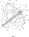
図1を参照すると、本発明の基本3次元構造モジュール(以下、3Dモジュール)は、下部基面の頂点ABCDおよび上部基面の頂点EFGHを有する6つの平面的な面によって画定される直方体12を構成する形状を有するモジュール構造ユニットである。図示の例では、なんら限定することなく、この平行6面体が、長さ約10メートルの辺を有する幾何学的な立方体であると想定されている。基本3Dモジュールの形状を次のように説明することができる。すなわち、
この立方体の4つの非隣接かど(この場合ではB、D、E、およびG)は、切欠き表面SB、SD(見えていない)、SE、およびSGによって切り欠いてある。図1に示す切欠き表面は、この立方体のそれぞれの切欠きかどを中心とする球面であるが、それらは、楕円面のようにこの立方体の中心に向かって膨出する任意の形状、または平坦な形状、またはより複雑な形状であり得る。
4つのトンネルTB、TD、TE、およびTGが形成され、かつこの立方体の中心で交わり、切欠き表面を相互連結するテトラポット状の通路を形成する。これらのトンネルを円筒管として示すが、他の形を有してもよい。
元の立方体の面、たとえば、表面14(面EFGH)から残された6つの平面的な表面は、この3Dモジュールが他の同様のモジュールと接触する基面である。これらの表面は、下で示すように、組立工程時に実質的に水平な土台上にモジュールを確実に安定して位置決めするのに十分な大きさでなければならない。
【0031】
図2は、2段に配置されている(上部前側のモジュールを取り除いている)、図1に示した種類の8個の3Dモジュールから組み立てられた構造体20の一部を示す。元の立方体(図1)の配置にしたがって3Dモジュールを積み重ねかつ組み立てることによって、トンネル(26、28)によって相互連結される大きな球面(22、24)が造り出される。したがって、基本3Dモジュールから建造した半潜水式の海上構造体は、それを通過して海水が自由に流れ得るようになる。
【0032】
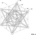
このような3Dモジュールは、元の立方体の面から残された平面表面上の6本の対角線(AF、FC、CA、AH、HC、およびHF)に沿って延在する強化対角線ビーム(RDB)で形成されている。これらのRDBは、強化要素、たとえば鋼鉄ロッドと、これらの強化要素を埋設する材料、たとえばコンクリートを含むことができる。RDBは、3Dモジュールの4つの強化かど(R1かど)A、C、F、およびHのうちの3つによって連結されて4面体形状を形成する。3Dモジュールが構造体20の一部として積み付けられるとき、3Dモジュール全体に分布する力は主にRDB沿いに集中する。基本3Dモジュールの構造的挙動は、図3に模式的に示すように、6本のロッド34と4個の頂点コネクタ36から作製した4面体の構造的挙動と同様である。図2の組立構造体は、複数の4面体と8面体を間に含む、図4に示す空間構造40と同様の荷重を支える。ロッド34と頂点コネクタ36から組み立てられた多重4面体40は機械工学で知られており、その主要な利点は、頂点に加わる外的負荷がロッドの軸方向荷重として分布され、上で説明したように、構造体の大きな区域に分布される点にある。
【0033】
したがって、本発明の3Dモジュールは、有利な構造的挙動と、これらの水平表面(図1の表面14のような)上に積み重ねることによって、このような複数のモジュールを大規模構造体に組み立てる容易で効率的な方法を提供する。3Dモジュールの望ましい構造的挙動は、切欠きかどまたはトンネルによってはそれほどに備わらず、4面体を形成するRDBによって備わるので、元の立方体の4つのかどを切り欠くことができる。
【0034】
図1と、図5の拡大図を参照すると、凹部42が、3Dモジュールのかどで立方体の表面上に形成されている。強化ロッド32の端部44がこれらの凹部の中に露出している。2個から8個の3Dモジュール10が、共通のRかど、たとえば、図2のかど46に隣接して配置されるとき、これらの凹部は、かど接合部48を造り出すために、コンクリートの流込み用またはグラウトの注入用の型枠としての役割を果たす空洞を形成する。図1および以下で図7に示すように、同様の凹部52をR対角線に沿って形成することも可能であり、これらの内部にRDBの一部が同様に露出している。図5に示すように、これらの空洞を封止するように膨張式チューブなどの適切なガスケットを保持するために、インプリント50(imprints:刻みつけ)を凹部42および52の周囲に形成する。
【0035】
基本3Dモジュール(図1)は、これらの本体中に中空の水密容積を有し得る。このような容積によって、バラスト用途の海水、または必要に応じて任意の他の材料(すなわち、飲料水、燃料、下水、砂、および他の材料)を充填できる貯蔵槽が構成可能である。モジュール中の中空容積は、元の立方体の容積の約4分の1に相当し、これらの内容物の完全な制御を容易にする開口部および遮断弁を介して連結可能である。これらの要素はモジュール壁の任意適切な箇所に挿入可能であり、したがって図示されていない。
【0036】
制御可能な容積は、3Dモジュールに浮力特性を付与するのに十分な大きさである。空気を導入することによって、3Dモジュールの浮力に加えて、組立構造体全体としての浮力も制御することができる。
【0037】
図6に示すように、基本3Dモジュール10は4個のシェル要素54から構築されており、これらは、組み立てられたモジュールでは、立方体の対角線上の継目に沿って緊密に連結されている。シェル要素54は、図7でも分かるように、平面壁(アーチ部)56、トンネル壁58、および球面壁60を備える。シェル要素54の縁部上の凹部52を使用して隣接3Dモジュール間のコネクタを成型することができる。
【0038】
図6、7、および8を参照すると、基本3Dモジュールは、以下の工程によってシェル要素54から製造される。
【0039】
段階「A」:最初に3個のアーチ部56を成型することによってシェル要素54を製造する。成型は平坦な型枠内で水平に実行可能である。RDBを作製するために鋼鉄強化ロッド32を使用し、ロッドの自由端44を爾後の連結用に凹部42中に露出しておく。凹部52を形成しかつ横軸強化ロッド(図示せず)も配設し、コンクリートを流し込む次段階で他のシェル部分に連結するために、鋼鉄の自由端をシェル要素の縁部沿いに配置する。
【0040】
段階「B」:それぞれのシェル要素54のために、3個のアーチ部56を成型用の型枠中に配置する。RDB用の追加的な強化ロッドと、同じく成型の間に埋設しなければならないフランジ、弁、浮力制御用のコック、貯蔵コンテナの開/閉用ハッチ、吊上げ用アイ・ボルトなどのすべての取付け要素を型枠中に挿入することができる。鋼鉄の自由端は、たとえば、溶接によって連結可能である。シェル要素の型枠は、両面または片面、もしくは両方の組合せが可能である。たとえば、トンネル58を両面型枠で成型することができる。海上構造体に関して、シェル要素の型枠は、成型されたコンクリート要素と一緒に浮遊している(浮揚性がある)ことが好ましい。
【0041】
段階「C」:コンクリートを型枠に流し込むことによってシェル要素の製造を終了する。球面壁60とトンネル壁58を成型し、平面アーチ部56間の間隙を充填する。したがって、すべての部分が連結され、シェル要素54が完成する。コンクリートの養生は型枠の内側で実行可能であり、必要であれば、水面に浮遊している間に行うことができる。養生が完了すると、シェル要素54は、3Dモジュールを形成するために他の3個のシェル要素との組立準備が完了している。
【0042】
段階「D」:内部にシェル要素54を有する4個の成型用の型枠をヒンジ手段によって相互に結合して、大型の折り畳み可能な三角形(図8A)を形成する4個の正三角形の配置にする。
【0043】
段階「E」:成型用の型枠をシェル要素54と一緒にヒンジ回りに「折り畳み」(互いに引き寄せて)、「擬似4面体」構造(図8Bおよび8C)を形成する。ここで、4個のシェル要素は、3次元空間のそれらの正確な位置に固定する。この段階の最後に、大型の単一外部型枠が出来上がる。
【0044】
段階「F」:型枠を閉じるとき、4個のトンネル壁58も相互に向かって閉ざされ、管状テトラポット61(図9)を形成する。これらの壁58間の間隙を3Dモジュールの内部側から閉ざすために、特殊な円弧状の帯62を壁58間の間隙に挿入し、かつ連結要素63手段によって壁の外側(テトラポットを貫通する通路に対して)で引っ張る。ここで、コンクリートの流込みまたは粘着性モルタルの塗付けまたはショットクリーチング(shotcreting)によって、トンネル壁58の縁部間の接合部を封止することができる。
【0045】
段階「G」:シェル要素52の縁部間の「継目」を接着する。横軸強化ロッドの端部を連結し、グラウトまたはコンクリートをシェル要素の縁部間に注入する。継目を閉ざすことによって、3Dモジュールはその最高の強度とその計画通りの構造的挙動を実現し得る。
【0046】
密閉した3Dモジュールとその型枠が浮遊能力を有する場合は、密閉した型枠とその内部の養生した3Dモジュールを水中に降ろし、浮揚状態にする。3Dモジュールとその型枠が、浮力に関する限り均衡したら、型枠を開き、3Dモジュールを解放して水面に浮遊させる。その浮力は、バラスト水、ブイ、および/または重りならびに巻上機によって制御可能である。
【0047】
本発明によれば、3Dモジュールの他の実施例も提案されている。連続的な平坦構造表面を実現する目的のために、特殊表面モジュール66を設計することができる(図10)。このモジュールは、4つの非隣接の切欠きかどのうちの2つのみを有し、かどEおよびGは完全である。組立構造体の露出かどのための3Dモジュール68は、3つの完全なかどを有することができる(かどBのみが切り欠いてある)。
【0048】
単純化した平坦面3Dモジュール70を図11に示す。この場合には、切欠き表面72が平面である。このような平坦面モジュールから構築した構造体74を図12に示す。この種類の3Dモジュール間の空間は、図2に示した球面体ではなく8面体の形状を実現する。
【0049】
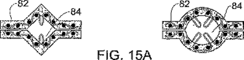
代替の「スケルトン」3Dモジュール80を図13に示す。このスケルトン・モジュールは、基本3Dモジュールと同じ外部形状(テトラポット中に4つの切欠きかどおよび連結した4つのトンネル)を有し、RDBから作製された同じ強化構造も有する。しかし、このスケルトン・モジュール80は、中空容積がなく、したがって浮力がない。スケルトン・モジュールは、4面体構造中に配置された概ね均一の断面を有する6本のビーム82を備える。これらのビームの断面は長方形になり得るが、2個の隣接するスケルトン・モジュールが、これらの間に元の立方体のR対角線に沿って延在する中空の空間を画定するように、開いた溝84を備えることもできる。隣接するスケルトン・モジュールによって組み立てた構造体が図14に示してあり、溝84を有する2本の隣接ビーム82の断面を図15Aで見ることができる。溝84中の中空の空間は、凹部42または52によって形成した空洞と同じ連結機能を有する。強化要素の一部は、その空間内に、たとえば、横軸鋼材ロッドの端部またはループを露出させることができる。この空間にグラウトまたは他の固定材料を充填して隣接モジュールのRDBを相互に固着して組立構造体の構造的挙動を向上させる。
【0050】
構造的挙動を向上させる別の方法は、「T」字形または「U」字形、もしくはビーム82の平坦面に対して垂直方向に慣性モーメントが増大する他の任意の形状を使用することである(図15B参照)。
【0051】
スケルトン・モジュールの特性は、基本3Dモジュールの特性と同様である。これらを立方体のように積み上げ、かつ基本3Dモジュールと同じ方式で相互連結して、図3および4に関連して説明したように構造的に振る舞う大規模構造体86(図14参照)を形成することができる。
【0052】
中空コンクリート・ボックスは、それぞれにまたはその6つの面中に開口を備えても、または備えていなくても、1つの代替的な「立方体」3Dモジュールとしての役割を果たすことができる。このような代替実施例は、ボックスが密閉されかつ空気が充填されていれば浮力を有し得るし、またはそれに開口があれば浮力を有し得ない。それは、基本3Dモジュールと同じ強化材、たとえば、「立方体」モジュールに4面体の構造的特性を付与するRDBによって、常法で知られている他のコンクリート構造ボックスのいずれとも異なる。連結方式は、基本3Dモジュールと同じである。
【0053】
本発明の3Dモジュールの別の実施例は、「二重」3Dモジュールである。図16に示す二重モジュール90は、基本モジュールのRDBを有するが、立方体の他の6本の対角線(R2対角線)に沿って延在し、かつ第2の4面体形状を成す第2組の6本のRDB91も備える。図3では、第2の4面体は、破線で示したロッド92および頂点コネクタ94によって模式化してある。負荷の下での第2の4面体の構造的挙動は、第1の4面体のそれと同じである。実際に、これら2個の4面体間の相互に及ぼす影響は、それらのRDBがそれぞれ同じモジュール中に埋設されているにも拘わらず非常に少ない。
【0054】
二重3Dモジュール90は、その8つの頂点がすべて接合部として使用されるので、異なる方式で切欠きを設ける。12個の球面SAD、SABなどを立方体のそれぞれの辺の周りに切り欠き、12個のトンネルTAB、TBFなどを切欠き面から立方体の中心まで穴ぐりする。立方体の中心は、中央の球面を切り欠くことによってさらに中ぐり可能である。切欠き表面も異なる形を有し得るが、R1対角線とR2対角線を遮断してはならない。二重3Dモジュールは、基本モジュール10と同様にその本体中に中空の水密容積を有することができる。それを6個のモジュール要素から組立て可能であり、それぞれが2つの異なる4面体、たとえば、要素ABFE(少し影を付けて示す)に属する2本のRDBを備える。二重3Dモジュールはシェル要素からも組み立てることができる。別法として、このモジュールをスケルトン3Dモジュール96(図17参照)として構築可能であり、このような8個のモジュールから組み立てた構造体98を図18に示す。
【0055】
本発明の範囲内で、さらに多くのRDBを追加して様々な3Dモジュールを製造することができる。たとえば、図19に示すように、立方体の面の中心を連結する12本のRDBを二重モジュールに追加して内部8面体構造を形成するとき、「多重」3Dモジュール100が得られる。この多重モジュールは、内部8面体構造に付着した8個の4面体(たとえば、LMNE)によって構成されていると見なし得る。多重モジュールの構造的方式は、8個の基本3Dモジュール(図4参照)から組み立てられた構造体の方式と実際に同一である。多重モジュールは、対応する頂点Eの下のトライポッド形状中に集中するトンネル、たとえば、TEA、TEF、TEHを有することができる。接合部を形成する凹部は、立方体の頂点(凹部42)、立方体の対角線(凹部52)、そして立方体の面の中央(凹部104)に設けられる。多重3Dモジュールは、12個の、EMFLなどのシェル要素から組立て可能である。3個のこのようなシェル要素を最初に1つの成型用の型枠中に組み立てて中間セットAFHEを形成し、次いで、4組のこのようなセットを型枠と一緒に組み立て、図8A、8B、および8Cに示しかつこれらに関連して説明した3Dモジュールに組み立てることができる。これに代えて、EMFLなどのシェル要素を、最初にLMEおよびLMFなどの部分要素から組み立てることもできる。中空容積は、内部8面体構造と周囲4面体の両方の中に形成可能である。
【0056】
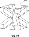
構成要素RDBが完全な4面体を形成しない「欠損」3Dモジュールは、本発明の3Dモジュールである。たとえば、図21は、二重交差の構成にある、囲んでいる立方体の4本の本体対角線に沿って4本のRDBを有する「欠損」3Dモジュール114を示す。これに代えて、図22は、囲んでいる立方体の面対角線のうちの5本の対角線に沿って5本のRDBを有し、1本の対角線FHを使用する空間4角形AFCHを形成する「欠損」3Dモジュール118を示す。最後のモジュールの構造は、辺ACが欠損する4面体AFCHであると説明することもできる。しかし、「欠損」3Dモジュールは、モジュール式構造体中で他の3Dモジュールと組み立てられるとき、完全な4面体格子の一部となる。図23では、このような構造120が、「欠損」3Dモジュール118から構築された2つのレイヤ122および124の一方を他方の上に設置する格子として示してある。上部レイヤ122中の欠損RDB126は、組み立てられた構造体では下部レイヤ124中のRDBに匹敵する。
【0057】
以上に説明した代替3Dモジュール、つまり、基本3Dモジュール、表面モジュール、平坦面モジュール、スケルトン・モジュール、立方体モジュール、二重モジュール、多重モジュール、および「欠損」モジュールは、すべてがモジュール方式であり、特定の平面要件にしたがって、相互に置換可能であるか、または組合せて(可換性がある)用いることが可能である。これらの可換性は、元の平行6面体の同じサイズ、R対角線に沿った平坦表面、および対応するR対角線に沿った接合部の同一または互換性のある配置によって備わる。しかも、多重モジュールは半分のサイズのモジュールによって組立て可能であり、それによって陸上および海上構造体のより融通性のある構成を提供する。
【0058】
海上構造体は、以下の方式で上に説明の3−Dモジュールから組み立てられる。
【0059】
海上構造体を建設するための海底および土台は、水中土木用の機械設備を使用する従来通りの方法によって整備する。必要であれば、砂礫投入または他の方法を使用して基盤を安定させることができる。
【0060】
海上建設物の土台は、静的かつ動的活荷重に加えて、自己荷重および海中に存在する動的負荷(海流、浮力、潮流、嵐、波、地震、海底地震など)に耐えるように設計される。さらには、これらの土台は構造体中の3Dモジュールを水平にする役割を果たす。
【0061】
3Dモジュールは、浮遊状態で、その所期の設置場所の上方に水中を運搬(曳航)される。モジュールは、構造体中のその最終位置に嵌め込むために、クレーン・ケーブルに連結され、回転され、かつその計画位置まで持ち上げられる。
【0062】
モジュールは、その中空容積中に制御量の水を流入させることによって、ブイを使用することによって、または吊上げクレーンなどを使用することによって水中に沈められる。3Dモジュールを定位置に適正に位置決めする最終微調整は、成型時または他の適切な方法によってモジュール中に取り付けられるコニカル・リード(conical leads)(オスおよびメス)によって実行可能である。
【0063】
隣接モジュールの凹部42が、かど接合部48(図5および図2)を成型するための型枠の役目をする密閉空間を形成するように、すべてのモジュールを共通のRかど回りに(1つのRかど当たり最大8個のモジュール)位置決めした後に、隣接する3Dモジュール間の連結を以下の方式で完成する。
接合部の型枠は、モジュール間の狭い間隙中で相互に向き合うインプリント50(図5)中に、空圧式または油圧式の膨張チューブなどのガスケットを挿入することによって成型のための準備をする。このようなガスケットは、モジュールを組み立てる前に、たとえば、接着によってインプリント中に取り付けてもよい。2組の複数のガスケットを使用し、ガスケットの1つが膨張しなければ、対向する1つが間隙を封止するように、各組がそれぞれのモジュールに付着して他方の組と向き合っていることが好ましい。適切な強化材(強化用の鋼鉄ロッド、強化ネット、強化繊維、強化ピン、または他の任意の強化手段)をモジュール中に挿入可能であり、強化ロッド32の露出端44を連結する。8個よりも少ないモジュールが接合部(すなわち構造体の境界)で接する場合は、型枠を適切なカバーによって密閉することができる。
グラウト注入管は、モジュール間の球形容積の方向から、型枠の上端中に設けてあり、3Dモジュールの製造時に予め取り付けておくのが好ましい。海水排出管は、型枠の下端中に設けてあり、同様にモジュール中に予め取り付けておくことが好ましく、さらに圧搾空気用の導管も設けられている。空圧/油圧式の膨張チューブを膨張させ、接合部型枠の密閉空間を取り囲む隣接モジュール間の間隙を封止する。
圧搾空気を型枠空間中に送出すると、海水が型枠から追い出されて排出管を下る。グラウトまたは他の凝固材料を注入管に通して注入し接合部型枠の空間内を充填する。グラウトを養生するとき、膨張式シーリング中の圧力を解放することができる。
【0064】
たとえば、連結要素用の凹部52(図1および7参照)または溝84(図15A)を使用して、追加的な接合部を3Dモジュール間に同様の方式で造り出すことができる。これらの連結要素は、2個のモジュールまたは4個のシェル要素に属する1本のR対角線回りのRDBを一体型ロッドとして機能させることになり、それによって重荷重の下でRDBが圧壊するのを防止する。
【0065】
最初に、3Dモジュールを2個以上のモジュールを含む浮マクロ・モジュール(集合)に組み立て、次いでこれらを建設現場に曳航し、位置決めし、かつ海上構造体の他の部分に連結することができる。この場合、マクロ・モジュールの組立ては、海上構造体の他の部分との連結に関与しない接合部のみによって、すなわち、凹部52、溝84、または完全に内部のRかどなどのみを使用することによって実行するのが好ましい。
【0066】
海上構造体の上部レイヤは、海水面(潮汐およびうねりを考慮して)よりも上に出るように設計されており、「表面」モジュール66および68(図10)から建造することができる。
【0067】
海上構造体または任意の3Dモジュールは、グラウトまたは他の凝固材を3Dモジュール中の中空容積に充填することによって強化可能であり、したがって、これらは、より大きな局部荷重に耐えるのに適切な局部的に強化された土台となる。
【0068】
3Dモジュールの設計強度とは関係なく、構造体を組み立てた後の別の随意選択的な局部強化は、追加的な支柱の組付けによるものである。3Dモジュール中の切欠き表面とトンネルは、構造体に沿って筒抜けの空間を残しておくような形状にすることができる。これらの空間を利用して支柱110を下方に海底まで挿入可能である(図20参照)。このような随意選択仕様を用いることによって、海上構造体の強度を事前に確定する必要がなくなる。このような支柱は、随時かつ必要に応じて追加可能である。
【0069】
上述の開放空間は、1個の3Dモジュールに4本まで支柱を挿通することができる。図20に示した支柱110の直径は、10×10×10メートルの寸法および6メートルのトンネル径を有するモジュールでは、1.50メートルである。この随意選択仕様は、すべての実用目的に関してかなりの活荷重を支持することができる。
【0070】
特定の実施例を説明してきたが、本発明の範囲から逸脱することなく、様々な変更がなされ得ることが企図されている。たとえば、3Dモジュールまたは構成シェル要素の製造に使用する構造材は鉄筋コンクリートに限定するものではない。ポリマー・コンクリート、アッシュ(フライアッシュ)・コンクリートに加えて、強化性の炭素繊維、ガラス繊維、プラスチック繊維、または鋼繊維も使用することができる。シェル要素は、成型用型枠として使用する繊維強化プラスチック(FRP)製の外部シェル中で成型可能であり、他方RDBはFRP製の内部副部材として形成可能である。
【0071】
以上に述べたように、それぞれの単一3Dモジュール中のRDBが閉じた4面体を形成する必要はない。RDBの幾本かが欠損している多様な「欠損」3Dモジュールは、本発明の範囲内で設計可能であり、1本または2本のみのRDBまたは相互に連結されていないRDBを備えるモジュールさえ設計可能である。このようなRDBは、組み立てられた海上または陸上構造体中に「欠損」3Dモジュールが含まれているときのみ、有利な多重4面体/8面体構造体の部材になることを理解されたい。
【図面の簡単な説明】
【0072】
【図1】本発明にしたがう基本3Dモジュールを示す斜視図である。
【図2】図1に示した8個の3Dモジュールから組み立てられた構造体を示す斜視図である。
【図3】単一構造4面体を示す模式図である。
【図4】多重4面体構造を示す模式図である。
【図5】3Dモジュールの強化かどを示す近接図である。
【図6】シェル要素から構築された3Dモジュールを示す分解組立図である。
【図7】シェル要素を示す分解図である。
【図8A】シェル要素を擬似4面体構造にする、4個のヒンジ付き型枠を折り重ねる工程を示す図である。
【図8B】シェル要素を擬似4面体構造にする、4個のヒンジ付き型枠を折り重ねる工程を示す図である。
【図8C】シェル要素を擬似4面体構造にする、4個のヒンジ付き型枠を折り重ねる工程を示す図である。
【図9】テトラポット状のトンネルの継目を成型するための伸縮性型枠を示す斜視図である。
【図10】1つおよび2つの切欠きかどを有する3Dモジュールから組み立てられた表面構造体を示す図である。
【図11】平坦面3Dモジュールを示す斜視図である。
【図12】図11の平坦面モジュールから組み立てた構造体を示す斜視図である。
【図13】「スケルトン」3Dモジュールを示す斜視図である。
【図14】「スケルトン」3Dモジュールから組み立てられた構造体を示す斜視図である。
【図15A】スケルトン3Dモジュール中のビームの断面を示す図である。
【図15B】スケルトン3Dモジュール中のビームの別の断面を示す図である。
【図16】本発明の「二重」3Dモジュールを示す斜視図である。
【図17】二重スケルトン3Dモジュールを示す斜視図である。
【図18】二重スケルトン3Dモジュールから組み立てられた構造体を示す斜視図である。
【図19】本発明の「多重」3Dモジュールを示す斜視図である。
【図20】基本3Dモジュールから組み立てられ、かつ垂直支柱によって強化されている構造体を示す斜視図である。
【図21】本体対角線上に4本のRDBを有する「欠損」3Dモジュールを示す斜視図である。
【図22】面対角線上に5本のRDBを有する「欠損」3Dモジュールを示す斜視図である。
【図23】「欠損」3Dモジュールから形成された完全な4面体格子を示す模式図である。【Technical field】
[0001]
The present invention relates to a method and means for building large scale structures and foundation structures on land and sea from prefabricated modules.
[Background]
[0002]
One preferred method for construction on the sea and on the shore is to assemble precast (assembled) steel reinforced concrete elements. It is also preferred to float these elements. The advantages of floating concrete structures include the economics of the materials used (concrete is very well suited to the marine environment), towing at the construction stage, as well as the ability to float the concrete structure for permanent floatation. While easy, they are sufficiently heavy as permanent equipment, and they can also be storage spaces. Concrete structures can be built in a convenient and safe location and then floated to the installation site. Such a method is used with the advantage of avoiding occupying expensive land for construction sites. Even if the installation site is greatly affected by the weather, it can be quickly installed in a short period of favorable conditions.
[0003]
The range of application examples of buoyant and non-buoyant concrete structures is very broad,
Crude oil exploration, drilling and production scaffolding, LPG base;
Dredging dock for boats, ships and yachts
There are artificial islands, airports, power plants, industrial plants, hotels, shopping centers, bridges, semi-submersible tunnels, lighthouses, breakwaters, etc. that are floating or based on the ocean floor.
[0004]
Large scale structures can be assembled from precast components that are integrated by in-place or match-cast joints. It is also possible to apply a combination of precast elements and on-site elements. A thin section of high-strength concrete is obtained by the precast method.
[0005]
An additional advantage is obtained by making the precast component modular, ie when the structure is assembled from a plurality of large, essentially identical modules. Thus, Japanese Patent No. 01127710 discloses a method for constructing a marine structure such as a scaffold or an artificial island from a hollow module having a round bottom having a diameter of about 10 meters and a depth of about 5 meters. These modules can take the form of a rectangular or hexagonal box, or a cylinder. They can be positioned by levitation, then towed and assembled in one or two directions in the horizontal plane as a large floating collection that can be connected to one large offshore structure.
[0006]
Japanese Patent No. 0120418 discloses a method for building a foundation for offshore structures from a large hollow T-shaped block. These blocks have dovetail vertical grooves on the connecting side and vertical wells for piles. Tow these blocks to the construction site and sink into place. Adjacent elements are connected by a steel or reinforced concrete profile inserted into a dovetail vertical groove and a support pile is driven through the vertical well into the seabed. The joint is formed in the dovetail by injection of mortar or grout.
[0007]
U.S. Pat. No. 3,799,093 discloses a prestressed concrete floating module for wharf assembly. The module is shaped like a rectangular box and has a core made of levitating material, pretensioned steel strands along the edge of the box, and a bracket for joining adjacent modules in a row.
[0008]
U.S. Pat. No. 5,107,785 describes the same concrete float module for use in floating docks, breakwaters, and the like. The box-shaped module has an integral tubular backing embedded along a set of parallel sides. A tension steel cable passes through these tubular backings and maintains several modules in a row in a pressurized state in series. Similar tubular liners can be provided in the transverse direction to interconnect several rows of modules. Yet another similar concrete module is disclosed in U.S. Pat. No. 6,199,502, where the module is also shaped like a box, but with a more stable interaction with adjacent modules. It has a slightly concave abutment side to ensure positioning. Each module is provided with passages for two sets of intersecting connecting cables in two planes offset from each other.
DISCLOSURE OF THE INVENTION
[Means for Solving the Problems]
[0009]
The present invention provides a method for easily assembling a cubic or box-like module to assemble a number of structural modules into a multi-tetrahedral structure. Specifically, a load bearing module structure assembled from a three-dimensional structure module (3D module) constituting a parallel hexahedron having a rectangular surface that is completely or partially cut away is provided. The 3D modules are joined together along the plane. The 3D module includes an enhanced diagonal beam (RDB) arranged along a diagonal line (R diagonal line) connecting the apexes (R corners) of parallelepipeds. The RDB forms a 3D multi-tetrahedral lattice of module structures so that the module structures behave as a multi-tetrahedron structure under load.
[0010]
According to a second aspect of the present invention, there is provided a 3D module for assembling into the module structure comprising at least one RDB comprising a reinforcing element. The RDB in the 3D module may be arranged along the plane R diagonal and / or along the body R diagonal and / or along the diagonal connecting the centers of the planes of the original parallelepiped. A single 3D module RDB does not necessarily form a complete tetrahedron or octahedron, but those RDBs are configured in a complete modular structure.
[0011]
One preferred embodiment of the 3D module (base module) is a set of six extending along six face diagonals (R1 diagonal) connecting four non-adjacent corners (R1 corners) of parallelepipeds. RDB. These RDBs are tetrahedrons so that the basic 3D module behaves substantially as a tetrahedron constructed from six rods connected at four vertices under a load applied to either R1. Form.
[0012]
Preferably, the other four corners (corners) of the parallelepiped are cut out along the four cutout surfaces, and the cutout surfaces intersect at the center of the parallelepiped to form a tetrapot shape 4. Interconnected by two respective tunnels.
[0013]
Preferably, the notch surface is an ellipsoidal or spherical shape centered on the respective notch corner, but can be any curved or planar shape. In particular, the notch surface and the tunnel can be shaped such that a portion of the 3D module that houses the RDB is essentially formed as a beam of uniform cross section. Alternatively, the notch surface and tunnel can be shaped to provide a free passage for the vertical struts parallel to the sides of the parallelepiped.
[0014]
In another embodiment of the 3D module of the present invention, there are six diagonal lines (R2) other than the R1 diagonal line of the box that do not have notched corners and the module connects four non-adjacent corners (R2 corners). And a second set of six RDBs extending along the diagonal), so that under a load applied to any of R2, this 3D module is connected to four vertices at six vertices. A second tetrahedron is formed to behave essentially as a tetrahedron constructed from rods. Such a double 3D module can cut out a part of the parallelepiped adjacent to the side, or can cut out a tunnel into the parallelepiped, Starting from one of these, all tunnels meet near the center of the parallelepiped. The dual module can be cut out so that a portion of the module containing the RDB forms a beam of uniform cross section that extends along the R1 and R2 diagonals. A dual 3D module can be assembled from six module elements, each module element comprising an RDB along the R1 diagonal and an RDB along the R2 diagonal.
[0015]
Yet another embodiment of the present invention, namely a “multiplex” 3D module comprising two sets of RDBs embedded in a double 3D module, but with 12 diagonals connecting the intersections of the R1 and R2 diagonals ( A third set of 12 RDBs extending along (R3 diagonal). The R3 diagonal line causes the octahedron to behave essentially as a multi-tetrahedron structure constructed from eight tetrahedra arranged around one octahedron under load. Form. A “multiplex” 3D module can be assembled from 12 module elements, each module element having one RDB along the R3 diagonal and a portion of the two RDBs along the two R1 diagonals. And a part of two RDBs along two R2 diagonals.
[0016]
Thus, the present invention is known that structures assembled from rods and apex connectors in a form such as a tetrahedral or octahedral grid (see FIG. 3 and FIG. 4 below) are very stable and robust. Based on the principles of structural mechanics. The principle advantage of these structures is that any external load applied to the apex is distributed as the axial load of the rod. Thus, the rod acts only on compressive force or tension, not on bending, torsional moments or shear strain. With such a configuration organized into a multi-tetrahedron structure comprising several layers, e.g. several layers of tetrahedrons (Fig. 4), the local load from one vertex is very quickly and evenly It is also distributed to more remote vertices. For this reason, it is not necessary to support such a multi-tetrahedral structure at all vertices facing the foundation (eg, the seabed), but can allow some unreinforced vertices, such as bridges. . The multi-tetrahedron structure has a number of overlapping connections, i.e., some of the rods can be removed without losing much rigidity. Thus, such a structure is extremely reliable even if some members may be structurally damaged, for example in the event of an accident, collision or other local destruction. . Moreover, the multi-tetrahedron structure is open and isomorphic and can be expanded in all directions without limitation by simply adding a rod and apex connector. In fact, as the number of layers increases, this structure behaves like a foam material (with very large cavities) with rigid walls. Such materials have an excellent weight to load ratio.
[0017]
RDB can be strengthened by elements such as steel rods. The RDB may be a pretension type or a post tension type. The 3D module of the present invention has recesses on its parallelepipedal plane, in its R diagonal, that these recesses are on the other 3D module when two modules are placed adjacent to each other. It is arranged to define similar recesses and cavities. The cavity serves to accommodate a connecting element that secures the two modules together. Such recesses can take the form of grooves extending along the R diagonal, or can be formed in any of the Rs of the parallelepiped or in other locations along the R diagonal. Preferably, in order to make the connection more appropriate, the RDB reinforcement element, ie a part of the steel rod, is exposed in the recess. These recesses are formed with a peripheral groove that accommodates a sealing element, such as an inflatable gasket, to seal the cavity.
[0018]
In yet another embodiment of the invention, the 3D module comprises a sealed fluid tight hollow volume and has a valve that allows filling and withdrawal of this hollow volume. The hollow volume is preferably sized so that the 3D module can float in water when at least part of the hollow volume is filled with air.
[0019]
The basic 3D module preferably constitutes a structural shell that encloses the hollow volume. The shell can be assembled from four shell elements having a generally triangular shape, each shell element comprising one of the tunnels and a portion of the RDB, each pair of shell elements being a parallelepiped Are sealed together by their edges along one of the R1 diagonals and along the junction of the two respective tunnels.
[0020]
The third aspect of the present invention is:
a) molding four shell elements in each of the four shell molds;
b) Three of the molding molds are arranged around the fourth molding mold in a horizontal plane, and the edges of the three molding molds are arranged at the edge of the fourth molding mold by hinge means. Combining the parts;
c) assembling a 3D tetrahedral structure by lifting the three molds and turning them around the hinge;
d) to obtain a hollow fluid tight 3D structure module comprising the steps of bonding the joints between the edges of the shell elements along the R1 diagonal and bonding the joints between the tunnels. A manufacturing method is provided.
[0021]
Preferably, step (a) is carried out by first molding three planar walls for each shell element and then placing the planar walls in a molding form for the shell elements. In offshore structures, by using a mold floating mold frame that is held together with the 3D module until the mold floating mold is ballasted, balanced, and released from the 3D module ( It is preferable to carry out the steps from a) to (d).
[0022]
The fourth aspect of the present invention is:
a) transporting at least two 3D modules, and adjacent and aligned with each other such that their respective parallelepipeds have a common R diagonal and define a cavity therebetween; Fixing, and
b) forming a joining element in the cavity to bond the 3D modules together, thereby obtaining a mechanical structure that behaves essentially as a multi-tetrahedron structure under load; A method of assembling a land or offshore structure from a 3D structure module is provided.
[0023]
Several 3D modules can be assembled together and then transported and secured to another such assembly.
[0024]
When the structure is a subsea structure and a buoyant 3D module having a hollow volume is used, the 3D module is moved in a floating state above a predetermined location and easily controlled by any other appropriate means. Then, it can be submerged in place by filling the hollow volume with water.
[0025]
When assembling the structure on the ground or sea floor, the structure can be strengthened locally by inserting the vertical struts through the space formed in the 3D module to insert the vertical struts.
[0026]
The fifth aspect of the present invention provides a method for forming a molded joint in a sealed space between two adjacent modules of a submerged structure. These modules are divided by a narrow gap surrounding the enclosed space, and the surrounding water can flow into the enclosed space by this narrow gap. This method
a) providing a closed space; (1) a source of compressed air; (2) a flowable solidified material; and (3) a conduit for fluid communication between surrounding water;
b) providing in the narrow gap one or more inflatable tube gaskets surrounding the enclosed space and connected to a source of pressurized fluid;
c) inflating the gasket with pressurized fluid to seal a narrow gap surrounding the enclosed space;
d) expelling water from the enclosed space via conduit (3) by supplying pressurized air via conduit (1);
e) filling the enclosed space with the solidified material via the conduit (2).
[0027]
The module can have a recess that forms part of the enclosed space, and the conduit in step (a) can be incorporated during manufacture of the adjacent module or can be formed by a narrow gap or surface groove in the adjacent module It is. It is possible to enclose a gasket in a groove formed in the module and surround the sealed space, and fix two sets of gaskets to an adjacent module facing each other in a narrow gap. Even if one of them does not expand, the gap can be sealed. The method is suitable for molding a joint between any buildings.
[0028]
The present invention provides an effective method of constructing offshore and terrestrial structures and infrastructure structures from prefabricated modules,
The structure is assembled by stacking box-like modules, advantageously using their horizontal or vertical surfaces;
An assembly structure is a spatial structural framework constructed from reinforced diagonal beams, embedded in a suitable arrangement, with a structural connection between modules providing a continuous reinforced beam in the structure, And local loads are distributed over large areas and foundations of the structure,
The structure can bridge depressions or uneven foundations in the underlying ground (eg the seabed),
The structure is very reliable and can withstand the damage of many structural members,
The structure is relatively light and suitable for construction in seismic, soft or quick sand,
The structure has a large hollow volume that provides buoyancy for easy channel transport and assembly by levitation and filling, and this volume can also be used as a storage container;
The module contains a large tunnel, water flow can pass through this assembly structure,
The module is built as a shell structure, making efficient use of structural materials,
The module is manufactured from the same shell element that is molded in a floating formwork, and the same formwork can be advantageously used for the assembly of the module and the transport of waterways,
This method is suitable for constructing man-made islands, expanding existing islands and reclaiming new land in the sea. This method is suitable for large-scale civil engineering (redevelopment of discarded quarries). Etc.) and can be applied as a substitute (in whole or in part) instead of throwing in soil extensively, and the method can be used for construction of bridges, dams, wharfs, breakwaters, etc. .
[0029]
In order to understand the present invention and see how it can be practiced in practice, reference will now be made to the accompanying drawings, which illustrate one preferred embodiment only as a non-limiting example.
【Example】
[0030]
Referring to FIG. 1, a basic three-dimensional structure module (hereinafter referred to as a 3D module) of the present invention includes a
The four non-adjacent corners (in this case B, D, E, and G) of this cube are notched surfaces S B , S D (Not visible), S E , And S G Notched by. The notch surface shown in FIG. 1 is a spherical surface centered on each notch corner of the cube, but they can be any shape that bulges toward the center of the cube, such as an ellipse, or a flat surface. Shape, or a more complex shape.
4 tunnels T B , T D , T E , And T G And intersect at the center of the cube to form a tetrapot-like passage interconnecting the notch surfaces. Although these tunnels are shown as cylindrical tubes, they may have other shapes.
The original planar surface, for example the six planar surfaces left from the surface 14 (plane EFGH), is the base surface from which this 3D module contacts other similar modules. These surfaces must be large enough to ensure a stable and stable positioning of the module on a substantially horizontal foundation during the assembly process, as shown below.
[0031]
FIG. 2 shows a portion of a structure 20 assembled from eight 3D modules of the type shown in FIG. 1, arranged in two stages (with the upper front module removed). By stacking and assembling 3D modules according to the arrangement of the original cube (FIG. 1), a large spherical surface (22, 24) is created that is interconnected by tunnels (26, 28). Therefore, the semi-submersible offshore structure constructed from the basic 3D module can pass through it and the seawater can flow freely.
[0032]
Such a 3D module has an enhanced diagonal beam (RDB) extending along six diagonals (AF, FC, CA, AH, HC, and HF) on the planar surface left from the original cube face. It is formed with. These RDBs can include reinforcing elements, such as steel rods, and materials that embed these reinforcing elements, such as concrete. The RDB is connected by three of the four reinforcing corners (R1 corners) A, C, F, and H of the 3D module to form a tetrahedral shape. When the 3D module is stacked as part of the structure 20, the forces distributed throughout the 3D module are mainly concentrated along the RDB. The structural behavior of the basic 3D module is similar to the structural behavior of a tetrahedron made from six
[0033]
Thus, the 3D module of the present invention facilitates the assembly of multiple modules into a large structure by advantageous structural behavior and stacking on these horizontal surfaces (such as
[0034]
Referring to FIG. 1 and the enlarged view of FIG. 5, a
[0035]
Basic 3D modules (FIG. 1) may have a hollow watertight volume in their bodies. Such a volume can constitute a reservoir that can be filled with seawater for ballast applications, or any other material as needed (ie, drinking water, fuel, sewage, sand, and other materials). The hollow volume in the module corresponds to about one quarter of the original cubic volume and can be connected through openings and shut-off valves that facilitate complete control of their contents. These elements can be inserted at any suitable location on the module wall and are therefore not shown.
[0036]
The controllable volume is large enough to give the 3D module buoyancy characteristics. By introducing air, in addition to the buoyancy of the 3D module, the buoyancy of the entire assembly structure can also be controlled.
[0037]
As shown in FIG. 6, the
[0038]
Referring to FIGS. 6, 7, and 8, the basic 3D module is manufactured from the
[0039]
Stage “A”:
[0040]
Stage “B”: For each
[0041]
Stage “C”: Finishing the production of the shell element by pouring concrete into the formwork. The
[0042]
Stage “D”: Arrangement of four equilateral triangles, in which four molding forms with
[0043]
Stage “E”: The mold form is “folded” (drawn together) around the hinge together with the
[0044]
Stage “F”: When closing the formwork, the four
[0045]
Stage “G”: glue the “seam” between the edges of the
[0046]
When the sealed 3D module and its mold have floating ability, the sealed mold and its cured 3D module are lowered into the water and brought into a floating state. When the 3D module and its formwork are balanced as far as buoyancy is concerned, the formwork is opened and the 3D module is released to float on the water surface. Its buoyancy can be controlled by ballast water, buoys and / or weights and hoisting machines.
[0047]
According to the invention, other embodiments of 3D modules have also been proposed.
[0048]
A simplified flat surface 3D module 70 is shown in FIG. In this case, the
[0049]
An alternative “skeleton”
[0050]
Another way to improve structural behavior is to use a “T” or “U” shape, or any other shape that increases the moment of inertia in a direction perpendicular to the flat surface of the beam 82 ( (See FIG. 15B).
[0051]
The characteristics of the skeleton module are similar to those of the basic 3D module. These are stacked like a cube and interconnected in the same manner as the basic 3D module to form a large structure 86 (see FIG. 14) that behaves structurally as described in connection with FIGS. be able to.
[0052]
The hollow concrete box can serve as an alternative “cubic” 3D module, with or without an opening in each or its six faces. Such alternative embodiments may have buoyancy if the box is sealed and filled with air, or not if it has an opening. It differs from any of the other concrete structure boxes known in the art by the same reinforcement as the basic 3D module, eg, RDB, which imparts a tetrahedral structural property to the “cubic” module. The connection method is the same as that of the basic 3D module.
[0053]
Another embodiment of the 3D module of the present invention is a “dual” 3D module. The
[0054]
The
[0055]
Within the scope of the present invention, more RDBs can be added to produce various 3D modules. For example, as shown in FIG. 19, a “multiple”
[0056]
A “missing” 3D module in which the component RDB does not form a complete tetrahedron is the 3D module of the present invention. For example, FIG. 21 shows a “missing”
[0057]
The alternative 3D modules described above, namely basic 3D modules, surface modules, flat modules, skeleton modules, cubic modules, dual modules, multiple modules, and “missing” modules are all modular and specific Can be used interchangeably or in combination (commutable) according to the planar requirements. These commutations are provided by the same or interchangeable arrangement of the same size of the original parallelepiped, a flat surface along the R diagonal, and a joint along the corresponding R diagonal. Moreover, multiple modules can be assembled with half-sized modules, thereby providing a more flexible configuration of land and offshore structures.
[0058]
The offshore structure is assembled from the 3-D module described above in the following manner.
[0059]
The seabed and foundation for constructing the offshore structure will be maintained by conventional methods using mechanical equipment for underwater civil engineering. If necessary, gravel input or other methods can be used to stabilize the foundation.
[0060]
The foundations of offshore structures are designed to withstand static and dynamic live loads, as well as self-loading and dynamic loads existing in the sea (sea currents, buoyancy, tidal currents, storms, waves, earthquakes, submarine earthquakes, etc.) Is done. Furthermore, these foundations serve to level the 3D module in the structure.
[0061]
The 3D module is floated and towed (towed) under water above its intended installation location. The module is connected to the crane cable, rotated and lifted to its planned position to fit in its final position in the structure.
[0062]
The module is submerged by flowing a controlled amount of water into its hollow volume, by using a buoy, or by using a lifting crane or the like. Final fine tuning to properly position the 3D module in place can be performed by conical leads (male and female) mounted in the module at the time of molding or by other suitable methods.
[0063]
Adjacent module recesses 42 all around the common R corner (one) to form a sealed space that serves as a mold for molding the corner joint 48 (FIGS. 5 and 2). After positioning, up to 8 modules per R corner), the connection between adjacent 3D modules is completed in the following manner.
The joint form is prepared for molding by inserting a gasket, such as a pneumatic or hydraulic expansion tube, into the imprint 50 (FIG. 5) facing each other in a narrow gap between the modules. . Such a gasket may be attached during imprinting, for example by gluing, before assembling the module. If two sets of gaskets are used and one of the gaskets does not expand, each set may adhere to the respective module and face the other so that the opposite one seals the gap preferable. Appropriate reinforcements (reinforcing steel rods, reinforcing nets, reinforcing fibers, reinforcing pins, or any other reinforcing means) can be inserted into the module and connect the exposed ends 44 of the reinforcing
The grout injection tube is provided in the upper end of the mold from the direction of the spherical volume between the modules, and is preferably attached in advance when the 3D module is manufactured. The seawater discharge pipe is provided in the lower end of the formwork, and is preferably installed in advance in the module as well, and a conduit for compressed air is also provided. A pneumatic / hydraulic expansion tube is inflated to seal the gap between adjacent modules surrounding the sealed space of the joint form.
When the compressed air is sent into the formwork space, seawater is expelled from the formwork and goes down the discharge pipe. Grout or other solidified material is injected through the injection tube to fill the space in the joint form. When curing the grout, the pressure during the inflatable sealing can be relieved.
[0064]
For example, additional joints can be created in a similar manner between 3D
[0065]
First, the 3D modules can be assembled into floating macro modules (collections) containing two or more modules, which are then towed to the construction site, positioned, and connected to other parts of the offshore structure. In this case, the assembly of the macro module is only by joints that are not involved in connection with other parts of the offshore structure, i.e. by using only recesses 52,
[0066]
The upper layer of the offshore structure is designed to emerge above the sea level (considering tides and swells) and can be built from “surface”
[0067]
Offshore structures or any 3D module can be strengthened by filling the hollow volume in the 3D module with grout or other solidified material, so they are suitable local to withstand larger local loads. The foundation will be strengthened.
[0068]
Regardless of the design strength of the 3D module, another optional local reinforcement after assembly of the structure is due to the assembly of additional struts. The notch surface and the tunnel in the 3D module can be shaped to leave a hollow space along the structure. It is possible to insert the column 110 downward to the sea floor using these spaces (see FIG. 20). By using such an optional specification, it is not necessary to determine the strength of the offshore structure in advance. Such struts can be added at any time and as needed.
[0069]
In the above open space, up to four columns can be inserted into one 3D module. The diameter of the pillar 110 shown in FIG. 20 is 1.50 meters for a module having dimensions of 10 × 10 × 10 meters and a tunnel diameter of 6 meters. This optional specification can support significant live loads for all practical purposes.
[0070]
While specific embodiments have been described, it is contemplated that various changes may be made without departing from the scope of the invention. For example, the structural material used to manufacture 3D modules or constituent shell elements is not limited to reinforced concrete. In addition to polymer concrete, ash (fly ash) concrete, reinforcing carbon fibers, glass fibers, plastic fibers or steel fibers can also be used. The shell element can be molded in an outer shell made of fiber reinforced plastic (FRP) used as a mold for molding, while the RDB can be formed as an internal sub member made of FRP.
[0071]
As described above, it is not necessary to form a tetrahedron in which the RDB in each single 3D module is closed. A variety of “deficient” 3D modules in which some of the RDBs are missing can be designed within the scope of the present invention, even modules with only one or two RDBs or even interconnected RDBs Design is possible. It should be understood that such an RDB is a member of an advantageous multi-tetrahedron / octahedral structure only when a “missing” 3D module is included in the assembled marine or land structure.
[Brief description of the drawings]
[0072]
FIG. 1 is a perspective view showing a basic 3D module according to the present invention.
FIG. 2 is a perspective view showing a structure assembled from eight 3D modules shown in FIG. 1;
FIG. 3 is a schematic view showing a single structure tetrahedron.
FIG. 4 is a schematic diagram showing a multi-tetrahedron structure.
FIG. 5 is a close-up view showing an enhanced corner of a 3D module.
FIG. 6 is an exploded view showing a 3D module constructed from shell elements.
FIG. 7 is an exploded view showing a shell element.
FIG. 8A is a diagram illustrating a process of folding four hinged molds into a pseudo-tetrahedral structure for a shell element.
FIG. 8B is a diagram showing a process of folding four hinged molds into a quasi-tetrahedral structure for the shell element.
FIG. 8C is a diagram showing a process of folding four hinged molds into a quasi-tetrahedral structure for the shell element.
FIG. 9 is a perspective view showing a stretchable mold for molding a seam of a tetrapot-shaped tunnel.
FIG. 10 shows a surface structure assembled from a 3D module with one and two notches.
FIG. 11 is a perspective view showing a flat surface 3D module.
12 is a perspective view showing a structure assembled from the flat surface module of FIG. 11. FIG.
FIG. 13 is a perspective view showing a “skeleton” 3D module.
FIG. 14 is a perspective view showing a structure assembled from a “skeleton” 3D module.
FIG. 15A shows a cross section of a beam in a skeleton 3D module.
FIG. 15B shows another cross section of the beam in the skeleton 3D module.
FIG. 16 is a perspective view showing a “dual” 3D module of the present invention.
FIG. 17 is a perspective view showing a double skeleton 3D module.
FIG. 18 is a perspective view showing a structure assembled from a double skeleton 3D module.
FIG. 19 is a perspective view showing a “multiplex” 3D module of the present invention.
FIG. 20 is a perspective view showing a structure assembled from a basic 3D module and reinforced by vertical struts.
FIG. 21 is a perspective view showing a “defect” 3D module having four RDBs on the main body diagonal.
FIG. 22 is a perspective view showing a “defect” 3D module having five RDBs on a face diagonal.
FIG. 23 is a schematic diagram showing a complete tetrahedral lattice formed from “defect” 3D modules.
Claims (28)
(a)4個の前記シェル要素を4つのそれぞれのシェル成型用型枠で成型する工程と、
(b)前記RDBを含む前記シェル要素の縁部を互いに隣接させて前記成型用型枠のうちの3つを第4の成型用型枠の回りに配置し、そして、ヒンジによって前記3つの成型用型枠の対応する縁部を前記第4の成型用型枠の隣接縁部に結合する工程と、
(c)前記3つの成型用型枠を持ち上げて、これらを前記ヒンジ回りに旋回させることによって3D4面体構造を組み立てる工程と、
(d)3次元構造モジュールが、それを前記型枠から解放するときに得られるように、前記面R対角線に沿った、前記シェル要素の縁部間の接合部を接着し、前記トンネルの壁の間の接合部を接着する工程とを含む方法。 A method of manufacturing the three-dimensional structural module of claim 1 from the triangular structural shell element of claim 25, comprising:
(A ) molding the four shell elements with four respective shell molding molds;
( B) Three of the molding molds are arranged around a fourth molding mold with the edges of the shell elements including the RDB adjacent to each other, and the three moldings are performed by hinges. Coupling the corresponding edge of the mold to the adjacent edge of the fourth mold,
( C) assembling a 3D tetrahedral structure by lifting the three molds and turning them around the hinge;
( D) Gluing the joints between the edges of the shell elements along the plane R diagonal so that a three-dimensional structural module is obtained when releasing it from the formwork; Adhering the joint between the two.
Applications Claiming Priority (2)
| Application Number | Priority Date | Filing Date | Title |
|---|---|---|---|
| US30113301P | 2001-06-28 | 2001-06-28 | |
| PCT/IL2002/000523 WO2003002827A1 (en) | 2001-06-28 | 2002-06-27 | Modular marine structures |
Publications (3)
| Publication Number | Publication Date |
|---|---|
| JP2004530822A JP2004530822A (en) | 2004-10-07 |
| JP2004530822A5 JP2004530822A5 (en) | 2005-09-29 |
| JP4060790B2 true JP4060790B2 (en) | 2008-03-12 |
Family
ID=23162088
Family Applications (1)
| Application Number | Title | Priority Date | Filing Date |
|---|---|---|---|
| JP2003508785A Expired - Fee Related JP4060790B2 (en) | 2001-06-28 | 2002-06-27 | Modular offshore structure |
Country Status (10)
| Country | Link |
|---|---|
| US (1) | US7226245B2 (en) |
| EP (1) | EP1404927B1 (en) |
| JP (1) | JP4060790B2 (en) |
| AT (1) | ATE357564T1 (en) |
| DE (1) | DE60219014T2 (en) |
| DK (1) | DK1404927T3 (en) |
| ES (1) | ES2286261T3 (en) |
| IL (1) | IL159600A0 (en) |
| PT (1) | PT1404927E (en) |
| WO (1) | WO2003002827A1 (en) |
Cited By (1)
| Publication number | Priority date | Publication date | Assignee | Title |
|---|---|---|---|---|
| JP2018536787A (en) * | 2015-12-03 | 2018-12-13 | オーシャン ブリック システム(オー.ビー.エス.)リミテッド | Perforated structure that can be installed on the sea floor |
Families Citing this family (20)
| Publication number | Priority date | Publication date | Assignee | Title |
|---|---|---|---|---|
| FR2871484B1 (en) * | 2004-06-14 | 2006-09-08 | Sue Dominique Gabriel Bordes | NEW MODULAR AND RADIAL RECIFALE STRUCTURE |
| FR2891556B1 (en) | 2005-09-30 | 2009-06-05 | Rene Giordano | BUILDING BLOCK OF SUBSTITUTE WORKS |
| US7574830B2 (en) * | 2006-08-08 | 2009-08-18 | Christopher Baker | High strength lightweight material |
| US8132986B2 (en) * | 2008-09-18 | 2012-03-13 | I.M.F.S. International Marine Floatation Systems Inc. | Water ballasted wave attenuator |
| US9683346B2 (en) | 2009-01-15 | 2017-06-20 | Ocean Brick Systems (O.B.S.) Ltd. | Perforated structure mountable onto a seabed |
| EP2376712A2 (en) | 2009-01-15 | 2011-10-19 | Ocean Brick System (O.B.S.) Ltd. | A deep-water port |
| EP2430242A1 (en) * | 2009-05-10 | 2012-03-21 | Ocean Brick System (O.B.S.) Ltd. | Artificial island |
| US9032896B2 (en) * | 2010-06-09 | 2015-05-19 | China National Offshore Oil Corporation | Grouting and welding combined connection joint applied to a deepwater floating type platform and an offshore installation method thereof |
| IT1400611B1 (en) * | 2010-06-18 | 2013-06-14 | Ge Co S R L | MODULAR STRUCTURE FOR THE REDUCTION OF WAVE-BIKE ENERGY. |
| ES2356546B2 (en) | 2010-06-28 | 2011-09-14 | Alberto Alarcón García | A FORGED OR SIMILAR STRUCTURAL ELEMENT LIGHTENED BY WHICH THEY CAN DISCURRATE RECORDABLE FACILITIES. |
| EP3305988B1 (en) * | 2012-07-16 | 2021-03-17 | Neptunetech Ltd. | Energy dissipater |
| EP2716830B1 (en) * | 2012-10-02 | 2018-08-15 | FESTO AG & Co. KG | Lightweight construction structure |
| MY182009A (en) * | 2014-04-07 | 2021-01-18 | Nxt Building System Pty Ltd | Support structure |
| FR3054571B1 (en) * | 2016-07-29 | 2020-05-29 | Robert Joncoux | REINFORCED CONCRETE BLADE BREAKER HAVING FACTORY SIDE SHELL SHAPE OF SAINT JACQUES |
| US10774518B1 (en) * | 2017-10-12 | 2020-09-15 | Lockheed Martin Corporation | Systems and methods for joining space frame structures |
| EP3867139B1 (en) * | 2018-10-17 | 2023-09-13 | VSG mbH & Co. Energy KG | Floating body comprising at least one element made of foam glass and at least one one-piece or multi-piece support structure |
| NL2024156B1 (en) * | 2019-11-04 | 2021-07-19 | Marine Innovations And Eng B V | Underwater modular structure, module of or for said underwater modular structure and method of constructing an underwater modular structure |
| CN112356523B (en) * | 2020-08-29 | 2021-12-07 | 南京航空航天大学 | Gradient lattice energy absorption structure constructed by chiral cell based on programmable rigidity and 3D printing method thereof |
| US11359364B1 (en) | 2020-12-07 | 2022-06-14 | Lockheed Martin Corporation | Systems and methods for joining space frame structures |
| US11358738B1 (en) * | 2021-02-10 | 2022-06-14 | Lockheed Martin Corporation | Systems and methods for assembling space frame structures |
Family Cites Families (21)
| Publication number | Priority date | Publication date | Assignee | Title |
|---|---|---|---|---|
| US1875668A (en) * | 1931-06-08 | 1932-09-06 | Daniel F Sheldon | Method of casting tetrahedrons |
| US2028794A (en) * | 1934-03-13 | 1936-01-28 | Gerard H Matthes | Method of constructing revetments |
| US2178667A (en) * | 1937-02-27 | 1939-11-07 | Edith M Littlefield | Method of construction and structure resulting therefrom |
| US3665882A (en) * | 1970-03-16 | 1972-05-30 | Tancho D Georgiev | Buoyant structure |
| US3663346A (en) * | 1970-07-22 | 1972-05-16 | Nasa | Honeycomb core structures of minimal surface tubule sections |
| US3822499A (en) * | 1972-05-30 | 1974-07-09 | Vos J De | Toy building block suitable for a pad, raft or the like |
| US3799093A (en) * | 1973-05-07 | 1974-03-26 | W Thomson | Floating prestressed concrete wharf |
| CY1126A (en) | 1976-01-03 | 1982-02-19 | Papaeconomou L | Moulds made of reinforced plastics material for breakwater armour units |
| US4074497A (en) * | 1976-06-01 | 1978-02-21 | Taisaburo Ono | Underwater trusses for breakwater structure |
| US4554883A (en) * | 1983-06-10 | 1985-11-26 | Lane Wallace W | Modular floating structure |
| JPS60233249A (en) * | 1984-05-07 | 1985-11-19 | 小野田 淳次郎 | Developable truss |
| US5024036A (en) * | 1988-08-12 | 1991-06-18 | Johnson David W | Interlocking support structures |
| JPH01214644A (en) * | 1987-10-26 | 1989-08-29 | Osvaldo N Rodriguez | Tetrahedral body module structure for house |
| JPH0645924B2 (en) | 1987-11-12 | 1994-06-15 | 鹿島建設株式会社 | Offshore structure |
| JPH0647828B2 (en) | 1988-10-27 | 1994-06-22 | 株式会社熊谷組 | Offshore structure foundation construction method |
| US5097645A (en) * | 1989-07-17 | 1992-03-24 | Robert Sanderson | Space frame system |
| US5107785A (en) | 1990-12-07 | 1992-04-28 | Baxter Hal T | Floating dock and breakwater |
| US5505035A (en) * | 1992-06-24 | 1996-04-09 | Lalvani; Haresh | Building systems with non-regular polyhedral nodes |
| US5315806A (en) * | 1992-07-16 | 1994-05-31 | Da Casta Trias De Bes Alejandr | Structure for concrete frameworks and means and procedures for its making |
| US6205739B1 (en) * | 1998-10-09 | 2001-03-27 | Tomcat Global Corporation | Connector node |
| US6199502B1 (en) | 1999-08-27 | 2001-03-13 | Jerry L. Mattson | Concrete module for floating structures and method of construction |
-
2002
- 2002-06-27 PT PT02743596T patent/PT1404927E/en unknown
- 2002-06-27 US US10/482,080 patent/US7226245B2/en not_active Expired - Lifetime
- 2002-06-27 DK DK02743596T patent/DK1404927T3/en active
- 2002-06-27 JP JP2003508785A patent/JP4060790B2/en not_active Expired - Fee Related
- 2002-06-27 AT AT02743596T patent/ATE357564T1/en not_active IP Right Cessation
- 2002-06-27 DE DE60219014T patent/DE60219014T2/en not_active Expired - Lifetime
- 2002-06-27 IL IL15960002A patent/IL159600A0/en unknown
- 2002-06-27 EP EP02743596A patent/EP1404927B1/en not_active Expired - Lifetime
- 2002-06-27 ES ES02743596T patent/ES2286261T3/en not_active Expired - Lifetime
- 2002-06-27 WO PCT/IL2002/000523 patent/WO2003002827A1/en active IP Right Grant
Cited By (1)
| Publication number | Priority date | Publication date | Assignee | Title |
|---|---|---|---|---|
| JP2018536787A (en) * | 2015-12-03 | 2018-12-13 | オーシャン ブリック システム(オー.ビー.エス.)リミテッド | Perforated structure that can be installed on the sea floor |
Also Published As
| Publication number | Publication date |
|---|---|
| US20040182299A1 (en) | 2004-09-23 |
| EP1404927B1 (en) | 2007-03-21 |
| ATE357564T1 (en) | 2007-04-15 |
| US7226245B2 (en) | 2007-06-05 |
| DE60219014D1 (en) | 2007-05-03 |
| ES2286261T3 (en) | 2007-12-01 |
| IL159600A0 (en) | 2004-06-01 |
| WO2003002827A1 (en) | 2003-01-09 |
| JP2004530822A (en) | 2004-10-07 |
| EP1404927A1 (en) | 2004-04-07 |
| DE60219014T2 (en) | 2008-01-03 |
| DK1404927T3 (en) | 2007-07-30 |
| PT1404927E (en) | 2007-06-29 |
Similar Documents
| Publication | Publication Date | Title |
|---|---|---|
| JP4060790B2 (en) | Modular offshore structure | |
| CN108222496B (en) | Flexible pouring template and construction method | |
| US9915047B2 (en) | Energy dissipator | |
| US20190283845A1 (en) | Modular structures and method for construction thereof | |
| CN114182764B (en) | Foundation scour prevention device and construction method | |
| KR102310131B1 (en) | Floatable concrete block structure and manufacturing method therefor | |
| CN109518674B (en) | Artificial island segment, assembled artificial island and construction method of assembled artificial island | |
| KR100995667B1 (en) | System-block and construction method using the same | |
| JPH0921141A (en) | Construction of undersea or under-river tunnel | |
| US5024557A (en) | Method and apparatus for constructing an offshore hollow column | |
| JP7389893B2 (en) | Offshore structures and construction methods | |
| ITRM980284A1 (en) | METHOD AND EQUIPMENT FOR THE CONSTRUCTION OF THE GUARD WALLS OF THE PORTS AND OF ARTIFICIAL REEF BOTH REMOVABLE AFTER | |
| WO2018113654A1 (en) | Flexible casting mold and construction method | |
| IL159600A (en) | Modular marine structures | |
| KR102483534B1 (en) | Sofa block caisson and its installation method | |
| CN107912346B (en) | Net cage anchoring foundation suitable for hard seabed based on waste container transformation | |
| TWI513877B (en) | The anchored seismic isolated floating foundation system and construction method | |
| JPH03114992A (en) | Construction method for ocean floating structure | |
| CN115162412A (en) | Construction method of main span of long-distance multifunctional sea-crossing combined immersed tube tunnel | |
| JPH0423686B2 (en) | ||
| JPH10237875A (en) | Method for installing caisson | |
| JPS58138832A (en) | Caisson levee and construction thereof | |
| JPS5861087A (en) | Constructing method of dock using hull | |
| JPS58138805A (en) | Construction of coffering revetment work | |
| JPH11303095A (en) | Installing caisson method |
Legal Events
| Date | Code | Title | Description |
|---|---|---|---|
| A621 | Written request for application examination |
Free format text: JAPANESE INTERMEDIATE CODE: A621 Effective date: 20050627 |
|
| A711 | Notification of change in applicant |
Free format text: JAPANESE INTERMEDIATE CODE: A711 Effective date: 20051024 |
|
| A131 | Notification of reasons for refusal |
Free format text: JAPANESE INTERMEDIATE CODE: A131 Effective date: 20070515 |
|
| A601 | Written request for extension of time |
Free format text: JAPANESE INTERMEDIATE CODE: A601 Effective date: 20070815 |
|
| A602 | Written permission of extension of time |
Free format text: JAPANESE INTERMEDIATE CODE: A602 Effective date: 20070907 |
|
| A521 | Request for written amendment filed |
Free format text: JAPANESE INTERMEDIATE CODE: A523 Effective date: 20070918 |
|
| TRDD | Decision of grant or rejection written | ||
| A01 | Written decision to grant a patent or to grant a registration (utility model) |
Free format text: JAPANESE INTERMEDIATE CODE: A01 Effective date: 20071120 |
|
| A61 | First payment of annual fees (during grant procedure) |
Free format text: JAPANESE INTERMEDIATE CODE: A61 Effective date: 20071220 |
|
| FPAY | Renewal fee payment (event date is renewal date of database) |
Free format text: PAYMENT UNTIL: 20101228 Year of fee payment: 3 |
|
| R150 | Certificate of patent or registration of utility model |
Free format text: JAPANESE INTERMEDIATE CODE: R150 Ref document number: 4060790 Country of ref document: JP Free format text: JAPANESE INTERMEDIATE CODE: R150 |
|
| FPAY | Renewal fee payment (event date is renewal date of database) |
Free format text: PAYMENT UNTIL: 20111228 Year of fee payment: 4 |
|
| R250 | Receipt of annual fees |
Free format text: JAPANESE INTERMEDIATE CODE: R250 |
|
| FPAY | Renewal fee payment (event date is renewal date of database) |
Free format text: PAYMENT UNTIL: 20121228 Year of fee payment: 5 |
|
| R250 | Receipt of annual fees |
Free format text: JAPANESE INTERMEDIATE CODE: R250 |
|
| R250 | Receipt of annual fees |
Free format text: JAPANESE INTERMEDIATE CODE: R250 |
|
| R250 | Receipt of annual fees |
Free format text: JAPANESE INTERMEDIATE CODE: R250 |
|
| R250 | Receipt of annual fees |
Free format text: JAPANESE INTERMEDIATE CODE: R250 |
|
| R250 | Receipt of annual fees |
Free format text: JAPANESE INTERMEDIATE CODE: R250 |
|
| R250 | Receipt of annual fees |
Free format text: JAPANESE INTERMEDIATE CODE: R250 |
|
| R250 | Receipt of annual fees |
Free format text: JAPANESE INTERMEDIATE CODE: R250 |
|
| R250 | Receipt of annual fees |
Free format text: JAPANESE INTERMEDIATE CODE: R250 |
|
| R250 | Receipt of annual fees |
Free format text: JAPANESE INTERMEDIATE CODE: R250 |
|
| R250 | Receipt of annual fees |
Free format text: JAPANESE INTERMEDIATE CODE: R250 |
|
| LAPS | Cancellation because of no payment of annual fees |