JP4058628B2 - Clutch device, feeding device, recording device - Google Patents
Clutch device, feeding device, recording device Download PDFInfo
- Publication number
- JP4058628B2 JP4058628B2 JP2003095684A JP2003095684A JP4058628B2 JP 4058628 B2 JP4058628 B2 JP 4058628B2 JP 2003095684 A JP2003095684 A JP 2003095684A JP 2003095684 A JP2003095684 A JP 2003095684A JP 4058628 B2 JP4058628 B2 JP 4058628B2
- Authority
- JP
- Japan
- Prior art keywords
- gear
- clutch
- clutch member
- cam
- state
- Prior art date
- Legal status (The legal status is an assumption and is not a legal conclusion. Google has not performed a legal analysis and makes no representation as to the accuracy of the status listed.)
- Expired - Fee Related
Links
- 230000005540 biological transmission Effects 0.000 claims description 59
- 230000007246 mechanism Effects 0.000 claims description 16
- 239000000463 material Substances 0.000 claims description 11
- 230000002159 abnormal effect Effects 0.000 description 8
- 238000001514 detection method Methods 0.000 description 6
- 239000007788 liquid Substances 0.000 description 6
- 238000000926 separation method Methods 0.000 description 6
- 238000011144 upstream manufacturing Methods 0.000 description 6
- 230000000694 effects Effects 0.000 description 4
- 238000012840 feeding operation Methods 0.000 description 2
- 238000004519 manufacturing process Methods 0.000 description 2
- 238000000018 DNA microarray Methods 0.000 description 1
- 230000008859 change Effects 0.000 description 1
- 230000002542 deteriorative effect Effects 0.000 description 1
- 238000010586 diagram Methods 0.000 description 1
- 239000007772 electrode material Substances 0.000 description 1
- 239000004973 liquid crystal related substance Substances 0.000 description 1
- 230000002093 peripheral effect Effects 0.000 description 1
- 230000002265 prevention Effects 0.000 description 1
- 230000009467 reduction Effects 0.000 description 1
- 230000007704 transition Effects 0.000 description 1
Images


Landscapes
- Sheets, Magazines, And Separation Thereof (AREA)
- Handling Of Sheets (AREA)
Description
【0001】
【発明の属する技術分野】
本発明は、記録用紙等の被記録材を給送する給送装置および該給送装置を備えた記録装置に関する。また、本発明は、駆動モータによって回動駆動される第1の歯車から、該第1の歯車によって動力が伝達される他の歯車への動力伝達のオンおよびオフを行うクラッチ装置に関する。
【0002】
ここで記録装置とは、インクジェット式記録ヘッドが用いられ、該記録ヘッドからインクを吐出して被記録媒体に記録を行うプリンタ、複写機およびファクシミリ等の記録装置に限らず、インクに代えてその用途に対応する液体を前記記録ヘッドに相当する液体噴射ヘッドから被記録媒体に相当する被噴射媒体に噴射して、前記液体を前記被噴射媒体に付着させる液体噴射装置を含む意味で用いる。
【0003】
液体噴射ヘッドとして、前記記録ヘッドの他に、液晶ディスプレー等のカラーフィルター製造に用いられる色材噴射ヘッド、有機ELディスプレーや面発光ディスプレー(FED)等の電極形成に用いられる電極材(導電ペースト)噴射ヘッド、バイオチップ製造に用いられる生体有機物噴射ヘッド、精密ピペットとしての試料噴射ヘッド等が挙げられる。
【0004】
【従来の技術】
記録装置の1つとしてインクジェットプリンタ(以下「プリンタ」と言う)があり、プリンタには、被記録媒体の一例である記録用紙をインクジェット記録ヘッド部へと1枚ずつ給送する給送装置(ASF)を備えるものがある。このような給送装置においては、記録用紙を給送する給送ローラが設けられ、そして該給送ローラの駆動源は、低コスト化の為、記録用紙をインクジェット記録ヘッド部へと搬送する搬送ローラ等の駆動源と兼用されるのが一般的である。尚、以下において、被記録媒体は記録用紙を代表例として説明するので、「被記録材」を「紙」または「記録用紙」、「給送」を「給紙」、「給送装置」を「給紙装置」、また「給送ローラ」を「給紙ローラ」とそれぞれいう場合がある。
【0005】
ここで、前記駆動源を成す駆動モータから搬送ローラおよび給送ローラへの動力伝達を行う際、例えば搬送ローラによって記録用紙を搬送する際には給送ローラの回動を停止させる必要があり、また、搬送ローラは正転および逆転の双方向の回転駆動を行う必要もあり、従ってこのような観点から、駆動モータから給送ローラへの動力伝達のオンおよびオフを実現するクラッチ装置が設けられている。(例えば特許文献1)
【特許文献1】
特開平10−329965号公報
【0006】
【発明が解決しようとする課題】
ところで、上述の様なクラッチ装置には、駆動モータによって常時回動駆動されるラチェット歯車と、該ラチェット歯車と噛合可能な歯部を有し、揺動することによって前記歯部と前記ラチェット歯車との係合状態および非係合状態とを切り替えるクラッチ部材によって構成されるものがある。
【0007】
しかし、ラチェット歯車と前記歯部とがその係合状態を解除する際に、当該解除動作が確実に行われないと、ラチェット歯車と前記歯部とが僅かに接触した状態となり、駆動時に異音(接触音)を発生させることになり、好ましくない状態を招くことになる。
【0008】
そこで本発明はこの様な状況に鑑みなされたものであり、その課題は、歯車と、該歯車と噛合可能な歯部との係合状態を確実に解除することにより、以て駆動時に異音を発生させない様にすることにある。
【0009】
【課題を解決するための手段】
上記課題を解決するために、本発明に係る第1の態様のクラッチ装置は、駆動モータによって回動駆動される第1の歯車から、該第1の歯車によって動力が伝達される第2の歯車への動力伝達のオンおよびオフを行うクラッチ装置であって、前記第2の歯車の回動軸に設けられるカムと、該カムに圧接する様に設けられるカムフォロアと、前記第1の歯車と噛合可能な歯部を有し、且つ、揺動可能に設けられ、揺動することにより、前記歯部と前記第1の歯車との歯車係合状態および歯車非係合状態を切り替えるクラッチ部材と、該クラッチ部材を前記歯部が前記第1の歯車と係合する方向に揺動付勢するクラッチ部材付勢手段と、前記クラッチ部材を揺動可能に保持し、且つ、前記クラッチ部材が前記歯車係合状態にある際に、前記クラッチ部材から動力を受けて前記クラッチ部材と共に回動する前記第2の歯車と、前記クラッチ部材に設けられたクラッチ係合部とのクラッチ係合状態およびクラッチ非係合状態とを切り替え可能に設けられ、前記クラッチ部材および前記第2の歯車が回動中において前記クラッチ非係合状態から前記クラッチ係合状態となることにより、前記クラッチ部材を揺動させて当該クラッチ部材を前記歯車係合状態から前記歯車非係合状態に切り替えるクラッチレバーと、を有し、前記カムにおけるカム面に凹部が設けられ、該凹部に前記カムフォロアがカム機構用付勢手段の付勢力によって嵌り込むことによって前記第2の歯車の回動軸が所定量回動する様に構成され、且つ、前記カムが前記カムフォロアとの係合を開始した際に、前記クラッチレバーが前記クラッチ係合状態となり、前記カムフォロアがカム機構用付勢手段の付勢力によって前記凹部に嵌り込むことによって前記第2の歯車が所定量回動し、これによって前記クラッチ部材が、前記クラッチ部材付勢手段の付勢力に抗して前記歯部が前記第1の歯車から離間する方向に所定量揺動する様に構成されていることを特徴とする。
【0010】
本発明の第1の態様によれば、第2の歯車の回動軸は第1の歯車によって回動駆動される。そして第2の歯車には、第1の歯車からクラッチ部材を介して動力が伝達される様になっている。一方、第2の歯車の回動軸にはカムが設けられ、該カムにはカムフォロアがカム機構用付勢手段の付勢力によって圧接するようになっている。そして、カムのカム面には凹部が設けられていて、該凹部にカムフォロアが嵌り込むと、第2の歯車の回動軸が所定量回動する様になっている。そして、第2の歯車の回動軸が所定量回動すると、クラッチ部材が所定量揺動して、以てクラッチ部材に設けられた歯部が第1の歯車から離間するので、これによって第1の歯車と歯部との係合状態を確実に解除することが可能となり、以て異音等の発生を防止することが可能となる。
【0011】
つまり、本発明は、カムに凹部を設け、該凹部にカムフォロアが嵌り込むことによって第2の歯車の回動軸を所定量回動させる様に構成したので、複雑な構成とならず、且つ、複雑な制御等をも行う必要なく、簡単に第1の歯車とクラッチ部材に設けられた歯部との係合状態を確実に解除することが可能となる。
【0012】
本発明に係る第2の態様のクラッチ装置は、駆動モータによって回動駆動される第1の歯車から、該第1の歯車によって動力が伝達される伝達歯車への動力伝達のオンおよびオフを行うクラッチ装置であって、前記伝達歯車と噛合する第2の歯車の回動軸に設けられるカムと、該カムに圧接する様に設けられるカムフォロアと、前記第1の歯車と噛合可能な歯部を有し、且つ、揺動可能に設けられ、揺動することにより、前記歯部と前記第1の歯車との歯車係合状態および歯車非係合状態を切り替えるクラッチ部材と、該クラッチ部材を前記歯部が前記第1の歯車と係合する方向に揺動付勢するクラッチ部材付勢手段と、前記クラッチ部材を揺動可能に保持し、且つ、前記クラッチ部材が前記歯車係合状態にある際に、前記クラッチ部材から動力を受けて前記クラッチ部材と共に回動する前記伝達歯車と、前記クラッチ部材に設けられたクラッチ係合部とのクラッチ係合状態およびクラッチ非係合状態とを切り替え可能に設けられ、前記クラッチ部材および前記伝達歯車が回動中において前記クラッチ非係合状態から前記クラッチ係合状態となることにより、前記クラッチ部材を揺動させて当該クラッチ部材を前記歯車係合状態から前記歯車非係合状態に切り替えるクラッチレバーと、を有し、前記カムにおけるカム面に凹部が設けられ、該凹部に前記カムフォロアがカム機構用付勢手段の付勢力によって嵌り込むことによって前記第2の歯車の回動軸が所定量回動する様に構成され、且つ、前記カムが前記カムフォロアとの係合を開始した際に、前記クラッチレバーが前記クラッチ係合状態となり、前記カムフォロアがカム機構用付勢手段の付勢力によって前記凹部に嵌り込むことによって前記第2の歯車の回動軸が所定量回動すると、前記伝達歯車が所定量回動し、これによって前記クラッチ部材が、前記クラッチ部材付勢手段の付勢力に抗して前記歯部が前記第1の歯車から離間する方向に所定量揺動する様に構成されていることを特徴とする。
【0013】
前記第1の態様は、駆動モータによって回動駆動される第1の歯車から、該第1の歯車によって動力が伝達される第2の歯車への動力伝達のオンおよびオフを行うクラッチ装置であって、第2の歯車の回動軸にカムが設けられている構成であるが、この第2の態様は、駆動モータによって回動駆動される第1の歯車から、該第1の歯車によって動力が伝達される伝達歯車への動力伝達のオンおよびオフを行うクラッチ装置であって、前記伝達歯車と噛合する第2の歯車の回動軸にカムが設けられている構成のものである。すなわち、第1の態様は伝達歯車を介さずに直接第2の歯車及びその回動軸に動力を伝達する構成であるのに対し、第2の態様は伝達歯車を介して、間接的に第2の歯車及びその回動軸に動力を伝達する構成である。
【0014】
即ち、本発明の第2の態様によれば、第2の歯車の回動軸は伝達歯車によって回動駆動され、そして当該伝達歯車には、第1の歯車、クラッチ部材の順に動力が伝達される様になっている。一方、第2の歯車の回動軸にはカムが設けられ、該カムにはカムフォロアが圧接する様になっている。そして、カムのカム面には凹部が設けられていて、該凹部にカムフォロアが嵌り込むと、第2の歯車の回動軸が所定量回動する様になっている。そして、第2の歯車の回動軸が所定量回動すると、伝達歯車が所定量回動し、その結果クラッチ部材が所定量揺動して、以てクラッチ部材に設けられた歯部が第1の歯車から離間するので、これによって第1の歯車とクラッチ部材に設けられた歯部との係合状態を確実に解除することが可能となり、以て異音等の発生を防止することが可能となる。
【0015】
本発明に係る第3の態様のクラッチ装置は、第2の態様において、伝達歯車は、複数の動力伝達可能に噛合する歯車で構成されていることを特徴とする。
【0016】
また、本発明に係る第4の態様のクラッチ装置は、第2の態様または第3の態様において、前記カムを、前記第2の歯車の回動軸に設けることに代えて、前記伝達歯車と一体に回動する伝達歯車軸に設けて成ることを特徴とする。前記カムフォロアがカム機構用付勢手段の付勢力によって前記カムの前記凹部に嵌り込むようにする当該カムは前記第2の歯車の回動軸に設けられていなくてもよく、伝達歯車の回動軸(伝達歯車と一体的に回動する回動軸)設けられていてもよい。この態様の発明によっても、第2の態様と同様の作用効果が得られる。
【0017】
本発明の第5態様に係る給送装置は、回動駆動される給送ローラ軸に設けられ、被記録材を給送する給送ローラと、上方に設けられた揺動支点を中心に揺動可能に設けられ、揺動することにより、前記給送ローラに被記録材を圧接させるホッパと、該ホッパを前記給送ローラに向けて付勢するホッパ用付勢手段と、前記給送ローラ軸に設けられ、前記ホッパに設けられたカムフォロアと係合することにより、前記ホッパ用付勢手段の付勢力に抗して前記ホッパを前記給送ローラから離間させるカムと、駆動モータから前記給送ローラに動力を伝達する歯車装置と、を備えた給送装置であって、前記歯車装置が、前記駆動モータによって回動駆動されるラチェット歯車と、前記ラチェット歯車と噛合可能な歯部を有し、且つ、揺動可能に設けられ、揺動することにより、前記歯部と前記ラチェット歯車との歯車係合状態および歯車非係合状態を切り替えるクラッチ部材と、該クラッチ部材を前記歯部が前記ラチェット歯車と係合する方向に揺動付勢するクラッチ部材付勢手段と、前記クラッチ部材を揺動可能に保持し、且つ、前記クラッチ部材が前記歯車係合状態にある際に、前記クラッチ部材から動力を受けて前記クラッチ部材と共に回動することによって前記給送ローラ軸に回動力を伝達する伝達歯車と、前記クラッチ部材に設けられたクラッチ係合部とのクラッチ係合状態およびクラッチ非係合状態とを切り替え可能に設けられ、前記クラッチ部材および前記伝達歯車が回動中において前記クラッチ非係合状態から前記クラッチ係合状態となることにより、前記クラッチ部材を揺動させて当該クラッチ部材を前記歯車係合状態から前記歯車非係合状態に切り替えるクラッチレバーと、を備え、前記カムにおけるカム面に凹部が形成され、該凹部に前記カムフォロアが前記ホッパ用付勢手段の付勢力によって嵌り込むことによって前記給送ローラ軸が所定量回動する様に構成され、且つ、前記カムが前記カムフォロアとの係合を開始した際に、前記クラッチレバーが前記クラッチ係合状態となり、前記カムフォロアが前記ホッパ用付勢手段の付勢力によって前記凹部に嵌り込むことによって前記給送ローラ軸が所定量回動すると、前記伝達歯車が所定量回動し、これによって前記クラッチ部材が、前記クラッチ部材付勢手段の付勢力に抗して前記歯部が前記ラチェット歯車から離間する方向に所定量揺動する様に構成されていることを特徴とする。
【0018】
第5の態様によれば、給送ローラの回動軸は伝達歯車によって回動駆動され、そして当該伝達歯車には、ラチェット歯車、クラッチ部材の順に動力が伝達される様になっている。一方、給送ローラの回動軸にはカムが設けられ、該カムにはカムフォロアが圧接する様になっている。カムフォロアはホッパに設けられていて、前記カムは、ホッパを給送ローラから離間させる機能を果たすものである。そして、カムのカム面には凹部が設けられていて、該凹部にカムフォロアが嵌り込むと、給送ローラの回動軸が所定量回動する様になっている。そして、給送ローラの回動軸が所定量回動すると、伝達歯車が所定量回動し、その結果クラッチ部材が所定量揺動して、以てクラッチ部材に設けられた歯部がラチェット歯車から離間するので、これによってラチェット歯車と歯部との係合状態を確実に解除することが可能となり、以て異音等の発生を防止することが可能となる。
【0019】
つまり、既存の構成要素であるカムに凹部を設け、該凹部にカムフォロアが嵌り込むことによって給送ローラ軸を所定量回動させる様に構成したので、複雑な構成とならず、且つ、複雑な制御等をも行う必要なく、既存の構成要素を利用して簡単にラチェット歯車と歯部との係合状態を確実に解除することが可能となる。
【0020】
本発明の第6態様に係る記録装置は、被記録材に記録を行う記録ヘッドと、該記録ヘッドを備え、主走査方向に往復動可能に設けられるキャリッジと、を有する記録装置であって、前記第5の態様の給送装置を備えていることを特徴とするものである。本態様によれば、被記録材に記録を行う記録装置において第5の態様の給送装置を備えているので、前述した第5の態様と同様な作用効果を得ることができる。
【0021】
本発明の第7態様に係る記録装置は、第6の態様において、前記クラッチレバーが、前記キャリッジの移動動作によって前記クラッチ係合状態と前記クラッチ非係合状態とを切り替える様に構成されていることを特徴とする。
本態様によれば、前記クラッチレバーが、前記キャリッジの移動動作によって前記クラッチ係合状態と前記クラッチ非係合状態とを切り替える様に構成されているので、給送ローラの回動駆動のオンおよびオフをキャリッジの移動動作によって行うことができ、以て特別な構成要素を必要とせず簡易な構成で給送ローラの回動駆動のオンおよびオフを行うことができる。
【0022】
【発明の実施の形態】
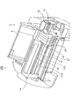
以下、図面を参照しつつ本発明の実施の形態について説明する。以下では先ず、本発明の一実施形態に係る記録装置の一例であるインクジェットプリンタ(以下「プリンタ」と言う)100の概略構成について図1および図2を参照しつつ説明する。ここで、図1はプリンタ100の装置本体(外観を構成するカバー部材を取り外した状態)の外観斜視図であり、図2は同側断面概略図である。尚、以下では、図1の右側(プリンタ100の後方側)を「上流側」(記録用紙搬送経路の上流側)と言い、図1の左側(プリンタ100の前方側)を「下流側」(記録用紙搬送経路の下流側)と言うこととする。
【0023】
プリンタ100は、図1に示す様に装置本体の基体を構成する、平面視略コの字形の形状をなすメインフレーム12の後方側に給送装置1を備え、該給送装置1から記録用紙を装置前方側へ1枚ずつ給送する。ここで、図2に示す様に給送装置1は、給送ローラ3と、分離パッド7と、紙戻しレバー9と、ホッパ5とを備えている。
【0024】
図示しない駆動モータによって回動駆動される給送ローラ3は側面視略D形の形状をなし、ローラ本体3aと、該ローラ本体3aの外周部に巻回されるゴム材3bとから構成されている。給送ローラ3は、その円弧部分によって記録用紙Pを給送する一方、平坦部分によって記録用紙Pを通過させて、下流側の搬送ローラ17による搬送動作時に搬送負荷を与えない様になっている。
【0025】
ホッパ5は板状体からなり、図示する様に傾斜姿勢に設けられ、且つ、上部に設けられた回動軸5aを中心に図2の時計方向及び反時計方向に揺動可能に設けられている。そして、後述するカム機構によって揺動駆動されることにより、下端部が給送ローラ3に対して圧接及び離間動作する様になっている。従って、ホッパ5が給送ローラ3に対して圧接方向に揺動すると、ホッパ5上に堆積された記録用紙Pの束は給送ローラ3に圧接し、そして当該圧接状態で給送ローラ3が回動することにより、堆積された記録用紙Pの最上位のものが下流側へと給送される。
【0026】
分離パッド7は、高摩擦部材からなり、給送ローラ3と対向する位置に設けられている。給送ローラ3が回動すると、給送ローラ3の円弧部分と分離パッド7とが圧接し、圧接部が形成される。給送ローラ3の円弧部分によって繰り出された最上位の記録用紙Pは、前記圧接部を通過して下流側へと進むが、最上位の記録用紙Pにつられて下流側へと進もうとする次位以降の記録用紙Pは、前記圧接部により、下流側への進行が阻止され、これによって記録用紙Pの重送が防止される。
【0027】
尚、分離パッドに代えて、リタードローラ等の他の分離部材すなわち重送防止手段を用いてもよい。リタードローラを用いるときは給紙ローラ3は側面視円形のものとなる。
【0028】
紙戻しレバー9はレバー形状をなし、ホッパ5の下端部近傍に配置され、回動支点9aを中心に図示しない駆動機構によって図2の時計方向および反時計方向に回動可能に設けられている。紙戻しレバー9は、記録用紙Pの給送動作時には図2に示す様に下流側に倒れた状態となっていて、記録用紙Pの給送を阻害しない状態となっている。そして、記録用紙Pの給送が始まり、給送される記録用紙Pの先端が紙戻しレバー9の下流側に進むと、紙戻しレバー9は上流側に向かって起き上がり、給送される記録用紙Pにつられて重送されようとする次位以降の記録用紙Pを上流側に押し戻す。これにより、記録用紙Pの重送が更に確実に防止される。
【0029】
次に、給送装置1の下流には板状体からなる紙案内15が略水平に設けられ、給送ローラ3によって繰り出された記録用紙Pの先端が該紙案内15に斜めに当接し、滑らかに下流側に案内される。紙案内15から下流には回動駆動される搬送駆動ローラ17aと、該搬送駆動ローラ17aに圧接する搬送従動ローラ17bとからなる搬送ローラ17が設けられ、記録用紙Pは、当該搬送駆動ローラ17aと搬送従動ローラ17bとにニップされて、記録(印刷)条件に応じたピッチで下流側に搬送される。ここで、搬送従動ローラ17bは搬送従動ローラホルダ21の下流側に軸支されていて、当該搬送従動ローラホルダ21は、回動軸21aを中心に図2の時計方向及び反時計方向に回動可能に設けられ、且つ、図示しないねじりコイルばねによって搬送従動ローラ17bが常に搬送駆動ローラ17aに圧接する方向(図2の反時計方向)に回動付勢されている。尚、搬送駆動ローラ17aは、主走査方向(図2の紙面表裏方向)に長い軸体からなり、搬送従動ローラ17bと搬送従動ローラホルダ21とは、共に搬送駆動ローラ17aの軸方向に複数配設されている(図示は省略)。
【0030】
次に、最も0桁側(図2の紙面表側)に位置する搬送従動ローラホルダ21近傍には、記録用紙Pの通過を検出する、センサ本体部19bと検出レバー19aとからなる紙検出器19が配設されている。検出レバー19aは側面視略「く」の字の形状をなし、その中央付近の回動軸19cを中心に図2の時計方向及び反時計方向に回動可能に設けられている。検出レバー19aの上方に位置するセンサ本体部19bは発光部(図示せず)及び該発光部からの光を受ける受光部(図示せず)を備え、検出レバー19aの回動軸19cから上側が、その回動動作により、前記発光部から前記受光部に向かう光の遮断及び通過を行う様になっている。従って、図2に示す様に記録用紙Pの通過に伴って検出レバー19aが上方に押し上げられるように回動すると、検出レバー19aの上側がセンサ本体部19bから外れ、これによって前記受光部が受光状態となって、記録用紙Pの通過を検出する様になっている。
【0031】
続いて、搬送駆動ローラ17aの下流には、プラテン27及びインクジェット記録ヘッド25が上下に対向する様に配設され、搬送ローラ17によってインクジェット記録ヘッド25の下へ搬送される記録用紙Pは、プラテン27によって下から支持される。インクジェット記録ヘッド25はインクカートリッジ24を搭載するキャリッジ23の底部に設けられ、該キャリッジ23は、主走査方向(図2の紙面表裏方向)に延び、メインフレーム12(図1)によって支持されるキャリッジガイド軸33により、主走査方向にガイドされる。
【0032】
図1において、メインフレーム12の両側部分には自由回動可能な従動プーリ13と、図示しない駆動モータによって回動駆動される駆動プーリ14とが設けられ、駆動プーリ14と従動プーリ13とには無端ベルト18が巻回されている。そしてキャリッジ23は無端ベルト18の一部に固定され、これにより、キャリッジ23が主走査方向に往復動する様になっている。そして、キャリッジ23が主走査方向に往復動しながら記録ヘッド25(図2)によってインクカートリッジ24から供給されたインク滴が吐出されることにより、記録用紙Pへの記録が実行される。
【0033】
次に、図2に戻って、インクジェット記録ヘッド25から下流は排出部(排紙部)となっていて、回動駆動される排紙駆動ローラ29aと、自由回動可能な排紙従動ローラ29bとからなる排紙ローラ29が設けられている。従ってインクジェット記録ヘッド25によって記録の行われた記録用紙Pは、排紙駆動ローラ29aと排紙従動ローラ29bとによってニップされた状態で排紙駆動ローラ29aが回動することにより、矢印方向に排出される。また、排紙従動ローラ29bのやや上流側には、自由回動可能な補助ローラ30が配設されている。ここで、排紙駆動ローラ29aは主走査方向にほぼ等間隔で複数個配設されていて、同様に排紙従動ローラ29bについても、これに合わせてほぼ等間隔で配設されている(図示は省略)。また、補助ローラ30は、排紙駆動ローラ29aと排紙従動ローラ29bからなる排出ローラ29のほぼ中間に配設されている(図示は省略)。
【0034】
ところで、搬送ローラ17と排紙(排出)ローラ29とは、協働して以下の様な作用効果を奏している。即ち、図2に示す様に、搬送ローラ17において搬送駆動ローラ17aと搬送従動ローラ17bとのニップ点がやや下流側に設定されていて、また、排紙ローラ29においては、排紙駆動ローラ29aと排紙従動ローラ29bとのニップ点がやや上流側に設定されている。従ってこれにより、搬送ローラ17と排紙ローラ29との間においては、記録用紙Pは図示する様に下に凸となる様な緩やかな湾曲状態となり、これにより、記録用紙Pがプラテン27に押し付けられる様になっている。その結果、記録用紙Pのプラテン27からの浮き上がりが防止され、記録面と記録ヘッド25との距離が一定に保たれるので、記録品質の低下を防止できる様になっている。
【0035】
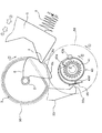
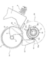
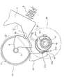
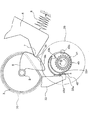
以上がプリンタ100の記録用紙搬送経路の構成であり、以下、図3乃至図11を参照しつつ、給送装置1のより詳細な構成について説明する。ここで、図3は給送ローラ3およびホッパ5を斜め下から見た斜視図であり、図4は給送装置1の側面側(図1において右側)に設けられる、給送ローラ3(給送ローラ軸2)への動力伝達のオンおよびオフを行うクラッチ装置(歯車装置)31の分解斜視図であり、図5は同組立図である。また、図6(a)、(b)はクラッチ部材43の動作原理を示す同クラッチ部材43の断面図であり、図7乃至図11はクラッチ装置31の動作原理を示す同クラッチ装置31の正面図(一部断面図)である。
【0036】
先ず、図3を参照しつつ、ホッパ5を揺動駆動するカム機構について説明する。図3に示す様に、ホッパ5はその下部の両側端側に給送ローラ3側に向かって突出する様なカムフォロア部7を有し、一方で給送ローラ軸2の両軸端側には、給送ローラ軸2の軸方向視において略扇形の形状をなし、カムフォロア部7と係合するカム6が、給送ローラ軸2と一体的に形成されている。一方、ホッパ5の背面側には、ホッパ5を給送ローラ3に向けて揺動付勢する付勢手段としてのホッパばね8(図2参照)が設けられていて、ホッパ5は、該ホッパばね8によって常に給送ローラ3に向けて揺動付勢された状態となっている。そして、図3から明らかな様に、給送ローラ3(給送ローラ軸2)の回動により、カム6とカムフォロア7との係合状態および非係合状態とが切り替わり、カム6がカムフォロア7を押し下げる係合状態(図3の状態)となることにより、ホッパ5が給送ローラ3から離間する様になっている。
【0037】
次に、図4乃至図6を参照しつつ、給送ローラ3(給送ローラ軸2)への動力伝達のオンおよびオフを行うクラッチ装置31の構成について説明する。
先ず、図4および図5において、クラッチ装置31は、図示しない駆動モータによって回動駆動される平歯車40を有し、従って該平歯車40が、クラッチ装置31への動力の入力部となっている。
【0038】
平歯車40はラチェット歯車41と一体的に形成されていて、該ラチェット歯車41には、該ラチェット歯車41の歯と噛合可能な歯部43aを円環形状の内部に有する、円環形状をなすクラッチ部材43が緩やかに嵌められる。クラッチ部材43は、その中心から偏倚した位置に軸受孔43bを有し、該軸受孔43bには、平歯車40とでクラッチ部材43を挟む様に設けられる「伝達歯車」としての平歯車39の、回動中心から偏倚した位置に設けられる突起軸39aが嵌合する様になっている。そして、ラチェット歯車41にクラッチ部材43の歯部43aが噛合した状態となると、クラッチ部材43はラチェット歯車41と共に回動し、そしてこれにより、平歯車39も回動する様になっている。
【0039】
平歯車39には、給送ローラ3の回動軸である給送ローラ軸2の軸端に設けられた給送ローラ歯車35が噛合していて、従ってクラッチ部材43の歯部43aがラチェット歯車41に噛合した状態で平歯車40が回動すると、結果的に給送ローラ軸2に回動力が伝達され、以て給送ローラ3が回動する様になっている。
【0040】
また、以上から明かな様に、クラッチ部材43の歯部43aがラチェット歯車41と噛合していない状態では、ラチェット歯車41はクラッチ部材43の円環の内部で空転するのみとなり、結果として平歯車40の回動力は、給送ローラ3へは伝達されない。尚、クラッチ装置31においては、図4および図5において図示しない軸体が、平歯車40、ラチェット歯車41、クラッチ部材43、平歯車39を挿通し、これにより、これら4つの回転体が同一の回転中心によって回動する様になっている。
【0041】
以上がクラッチ装置31の概要であり、以下、主にクラッチ部材31の動作原理について主として図6を参照しつつ、適宜図4をも参照しながら説明する。ここで、図6(a)は、上述した様にクラッチ部材43の歯部43aがラチェット歯車41と噛合して給送ローラ3へ回動力を伝達する状態を示していて、同図(b)は、クラッチ部材43の歯部43aがラチェット歯車41と噛合しておらず、給送ローラ3へ回動力を伝達しない状態を示している。
【0042】
図6(a)において、クラッチ部材43は軸受孔43bに突起軸39a(図4)が嵌合することにより、軸受孔43bを中心にして、図6の時計方向および反時計方向に揺動することができる様になっている。そして、揺動することにより、図6(a)に示す様な歯部43aとラチェット歯車41との噛合状態(歯車係合状態)となり、また、図6(b)に示す様な歯部43aとラチェット歯車41との非噛合状態(歯車非係合状態)となる。
【0043】
次に、クラッチ部材43にはばね掛止部43cが設けられ(図4も参照)、一方で平歯車39の側にもばね掛止部39bが設けられ(図4も参照)、これら2つのばね掛止部には、引っ張りコイルばね45が掛架されている。引っ張りコイルばね45は、歯部43aがラチェット歯車41と噛合する方向(ラチェット歯車41に圧接する方向)にクラッチ部材43を揺動付勢し、これにより、クラッチ部材43に外部から何らの力が作用していない状態では、歯部43aとラチェット歯車41とがしっかりと噛合する様になっている。そして、図6(a)から明かな様に、ラチェット歯車41は本実施形態においては図6(a)の反時計回りに歯が傾いていて、また、歯部43aもこの様に形成されたラチェット歯車41の歯と噛合する様に形成されているので、ラチェット歯車41が図6(a)に示す反時計方向に回動すると、クラッチ部材43に回動力が伝達され、そして平歯車39も図6(a)の反時計方向に回動し、この結果、給送ローラ3が記録用紙Pを下流側に給送する方向(図2の時計方向)に回動する。
【0044】
次に、クラッチ部材43の外周部には、クラッチ部材43が給送ローラ3に回動力を伝達する方向(図6(a)の反時計方向)に回動した際に、該クラッチ部材43の外周に位置するフック部33aと係合するクラッチ係合部43dが形成されている。
【0045】
ここで、フック部33aはフック形状をなし、クラッチレバー33(図4)の下部に形成されている。該クラッチレバー33は、回動軸33bを中心に回動することにより、下部のフック部33aがクラッチ部材43の外周に対して進退動作することができる様に設けられている。該クラッチレバー33には、前記フック部33aをクラッチ部材43の外周に押し付けるように付勢するクラッチレバー付勢用のばね53(図4)が設けられている。また、回動軸33bの上部(図示せず)が、キャリッジ23がクラッチ装置31が設けられた側(図1の右側)に移動してきた際に、当該キャリッジ23と係合可能となっていて、これにより、クラッチレバー33の上記回動動作(フック部33aの上記進退動作)が行われる様になっている。そして、これによってクラッチレバー33は、フック部33aとクラッチ係合部43dとが係合する「クラッチ係合状態」と、フック部33aとクラッチ係合部43dとが係合しない「クラッチ非係合状態」とを切り替えることができる様になっている。
【0046】
ここで、クラッチレバー33の前記フック部33aは、前記クラッチ係合部43dと当接する部分にテーパ形状のテーパ部33eが設けられている(図10及び図11)。これにより、フック部33aがクラッチ係合部43dと係合する方向(クラッチ部材の外周に押し付けられる方向)に進むと、そのテーパ部33eによってクラッチ部材43の歯部43aがラチェット歯車41から外れる方向に当該クラッチ部材43を揺動させる働きをして、その歯部非係合状態への移行が迅速且つ確実なものとなる。
【0047】
図6に戻って、ラチェット歯車41が給送ローラ3に回動力を伝達する方向(図6(a)の反時計方向)に回動中にフック部33aがクラッチ部材43の外周部に進出すると(図6(a)に示すフック部33aの状態)、フック部33aとクラッチ係合部43dとが係合し、クラッチ部材43の回動が止められる。しかし、ラチェット歯車41は更に回転しようとするから、ラチェット歯車41の歯は、歯部43aを図6(a)の矢印に示す方向に押し退けようとする。ここで、クラッチ部材43は、軸受孔43bを中心に揺動可能に設けられているから、ラチェット歯車41の歯が歯部43aを図6(a)の矢印に示す方向に押し上げようとする力によって、クラッチ部材43は引っ張りコイルばね45の付勢力に抗して揺動し、この結果、図6(b)に示す様なラチェット歯車41と歯部43aとの非噛合状態となる。
【0048】
以上がクラッチ部材43の動作原理であり、以下、給送ローラ3、ホッパ5の動きと共に、クラッチ装置31全体の動作原理について説明する。尚、以下では、ラチェット歯車41と歯部43aとが噛合し、これによって図示しない駆動モータから給送ローラ3に回動力が伝達される状態を、クラッチ装置31の「稼働状態」と言うこととする。
【0049】
先ず、図7は、給送装置1が給送待機状態から、給送動作に移った直後の状態を示している。この状態では、給送ローラ3は図示する様に側面視略D形の形状における平坦部をホッパ5に対向させた状態となっていて(図2に示す状態)、ホッパ5は、ホッパばね8のばね力に抗して給送ローラ3から離間した状態にある。より詳しくは、図3を参照しつつ説明したカム6とカムフォロア7とが係合した状態にあり、カム6が、カムフォロア7を介してホッパ5を下方に押し下げた状態となっている。従ってこの状態では、ホッパ5上にセットされた記録用紙Pは、給送ローラ3には圧接していない。
【0050】
そして、給送動作の開始時には、キャリッジ23(図1)がクラッチレバー33と係合して、図7に示す様にフック部33aがクラッチ部材43の外周部から退避してラチェット歯車41と歯部43aとが引っ張りコイルばね45の付勢力によって噛合状態となり、そしてクラッチ装置31が稼働状態となる。尚、図7乃至図9において符号▲3▼、▲4▼、▲5▼と共に実線で示す矢印は、それぞれ給送ローラ3(即ち、給送ローラ軸2、平歯車35、カム6)、平歯車39、クラッチ部材43のそれぞれの回転方向を示すと同時に、当該実線で示す矢印は、これら回転体が、クラッチ装置31が稼働状態となり、図示しない駆動モータの駆動力によって回動する状態を示している(これに対して、図10において破線で示す矢印は、駆動モータの駆動力ではない他の駆動力による回動を示している(後述))。また、符号▲1▼および▲2▼で示す矢印は、ホッパ5が揺動可能な方向を示している。
【0051】
次に、図7に示す状態から符号▲6▼で示す方向にラチェット歯車41が回動すると、図7から図8に示す変化の様に、カム6とカムフォロア7との係合が解かれ、ホッパ5は、ホッパばね8の付勢力によって給送ローラ3に圧接する方向(図7の符号▲1▼で示す方向)に揺動する。これにより、ホッパ5上にセットされた記録用紙Pが給送ローラ3に圧接し、給送ローラ3の回動と共に、最上位の記録用紙Pの給送が開始される。またこの時、キャリッジ23(図1)がクラッチレバー33との係合状態を解き、これにより、フック部33aが、前記ばね53の付勢力によって再びクラッチ部材43に進出した状態となる。
【0052】
次に、ラチェット歯車41が更に回動すると、図9に示す様にカム6とカムフォロア7とが再び係合を開始して、ホッパ5を給送ローラ3から離間する方向(図7の符号▲2▼で示す方向)に揺動させると共に、クラッチ係合部43dとフック部33aとが係合する。そして、図9に示す状態からラチェット歯車41が更に回動すると、ラチェット歯車41の歯が歯部43aを押し退け、これにより、クラッチ部材43は図9の矢印▲7▼で示す方向に揺動する。尚、カム6のカム面(円弧面)6aには、図示する様に凹部6bが形成されていて、図9に示す様にクラッチ係合部43dとフック部33aとの係合が開始した時点においては、カムフォロア7は、カム面6aの緩やかな円弧面に圧接した状態となっている。この状態で付勢力は、給送ローラ3とホッパ5の間には作用せず、カム6とカムフォロア7の間に作用する。
【0053】
次に、ラチェット歯車41が更に回動すると、図10に示す様にカムフォロア7がカム6に形成された凹部6bにさしかったと同時に、上述したクラッチ部材43の揺動動作によってラチェット歯車41と歯部43aとが非噛合状態となり、ラチェット歯車41は、符号▲8▼で示す様にいずれの方向にも自由に回動することができる様になる。即ち、クラッチ装置31が非稼働状態となり、ラチェット歯車41の回動力がクラッチ部材43に伝達されない状態となる為、給送ローラ3が回動せず、従って給送ローラ3と駆動源(駆動モータ)を同じくする搬送ローラ17(図2)が、いずれの方向に回動しても給送装置1に対して影響を与えない状態となる。
【0054】
ここで、クラッチ装置31は非稼働状態となるので、原則的には、平歯車39、給送ローラ歯車35、給送ローラ軸2はこの時点以降は回動しないことになる。尚、この状態に於いて、歯部43aは、ラチェット歯車41によって押し退けられる様にしてラチェット歯車41の歯から遠ざかる為、ラチェット歯車41の歯と接触するかしないか、いわばぎりぎりの状態(位置)にあり、場合によっては、ラチェット歯車41の回動に従って接触音(異音)が発生する状態となる。
【0055】
しかし、前述した様にカム6のカム面には凹部6bが形成されていて、しかもカムフォロア7は、ホッパばね8の付勢力が作用しカム6に圧接した状態となっている。そして、図10に示す状態では、カムフォロア7は凹部6bにさしかかった状態にあるので、ラチェット歯車41からの回動力の伝達が絶たれても、図10から図11に示す変化の様に、カムフォロア7が凹部6bに入り込む(嵌り込む)ことによって給送ローラ軸2を所定量(僅かに)回動させる。
【0056】
すると、これによって給送ローラ歯車35、平歯車39が所定量(僅かに)回動する。ここで、図10において符号▲1▼’とともに破線で示す矢印は、カムフォロア7が凹部6bに入り込むことによってホッパ5が僅かに揺動する方向を示していて、符号▲3▼’、▲4▼’とともに破線で示す矢印は、同じくカムフォロア7が凹部6bに入り込むことによって給送ローラ歯車35、平歯車39が所定量(僅かに)回動する方向を示している。
【0057】
次に、クラッチ部材43においては、平歯車39が僅かに回動すると、フック部33aとクラッチ係合部43dとが係合状態であるから、揺動支点としての軸受孔43bのみが平歯車39とともに僅かに回動し、これに伴い、クラッチ部材43は符号▲7▼’および破線で示す矢印の方向に僅かに揺動することとなる。すると、これにより、図11に示す様に歯部43aがラチェット歯車41から更に遠ざかり、前述した様な歯部43aがラチェット歯車41の歯と接触するかしないかの状態が解消され、ラチェット歯車41が回動しても、異音(接触音)が発生しない状態となる。
【0058】
つまり、本発明に係るクラッチ装置31は、既存の構成要素であるカム6に凹部6bを設け、該凹部6bにカムフォロア7が嵌り込むことによって給送ローラ軸2を僅かに回動させる様に構成したので、複雑な構成とならず、且つ、複雑な制御等をも行う必要なく、既存の構成要素を利用して簡単にラチェット歯車41と歯部43aとの係合状態を確実に解除することができ、これにより、クラッチ装置31が非稼働状態となった場合に、ラチェット歯車41がいずれの方向に回動しても、ラチェット歯車41と歯部43aとによる異音(接触音)の発生を防止することができる様になっている。
【0059】
上記においては、給送ローラ3の回動軸である給紙ローラ軸2は、伝達歯車である平歯車39を介して前記給紙ローラ軸2の軸端に設けられた給紙ローラ歯車35に動力伝達されることによって回動駆動され、そして当該平歯車39(伝達歯車)には、ラチェット歯車41、クラッチ部材43の順に動力が伝達される様になっている。一方、給送ローラ3の回動軸2には前記カム6が設けられ、該カム6には前記カムフォロア7が圧接するようになっている。カムフォロア7は、ホッパ5に設けられていて、前記カム6は、ホッパ5を給送ローラ3から離間させる機能を果たすものである。そして、カム6のカム面には凹部6bが設けられていて、該凹部6bにカムフォロア7が嵌り込むと、給送ローラ3の回動軸2が所定量回動するようになっている。そして、給送ローラ3の回動軸2が所定量回動すると、給紙ローラ歯車35と平歯車39(伝達歯車)が所定量回動し、その結果クラッチ部材43が所定量揺動して、以てクラッチ部材43に設けられた歯部43aがラチェット歯車41から離間するので、これによってラチェット歯車41と歯部43aとの係合状態を確実に解除することが可能となる実施形態を説明したが、本発明はこれに限定されず、以下のようにしてもよい。
【0060】
クラッチ装置として、駆動モータによって回動駆動される前記「ラチェット歯車41」に相当する第1の歯車から、該第1の歯車によって動力が伝達される「平歯車39」をそのまま前記「給紙ローラ歯車35」として兼用させて、すなわち前記平歯車41を給紙ローラ軸2の軸端に固定した構造に代えて第2の歯車とし、伝達歯車を用いずに第1の歯車から第2の歯車への動力伝達のオンおよびオフを行うクラッチ装置であってもよい。
【0061】
すなわち、前記平歯車41(「給紙ローラ歯車35」を兼ねる)に相当する第2の歯車の回動軸に設けられるカム6と、該カム6に圧接する様に設けられるカムフォロア7と、前記第1の歯車と噛合可能な歯部43aを有し、且つ、揺動可能に設けられ、揺動することにより、前記歯部43aと前記第1の歯車との歯車係合状態および歯車非係合状態を切り替えるクラッチ部材43と、該クラッチ部材43を前記歯部43aが前記第1の歯車と係合する方向に揺動付勢するクラッチ部材付勢手段(引っ張りコイルばね45)と、前記クラッチ部材43を揺動可能に保持し、且つ、前記クラッチ部材43が前記歯車係合状態にある際に、前記クラッチ部材43から動力を受けて前記クラッチ部材43と共に回動する前記第2の歯車と、前記クラッチ部材43に設けられたクラッチ係合部43dとのクラッチ係合状態およびクラッチ非係合状態とを切り替え可能に設けられ、前記クラッチ部材43および前記第2の歯車が回動中において前記クラッチ非係合状態から前記クラッチ係合状態となることにより、前記クラッチ部材43を揺動させて当該クラッチ部材43を前記歯車係合状態から前記歯車非係合状態に切り替えるクラッチレバー33と、を有し、前記カム6におけるカム面に凹部6bが設けられ、該凹部6bに前記カムフォロア7が、前記ホッパ用付勢手段8に相当するカム機構用付勢手段の付勢力によって嵌り込むことによって前記第2の歯車の回動軸が所定量回動するように構成され、且つ、前記カム6が前記カムフォロア7との係合を開始した際に、前記クラッチレバー33が前記クラッチ係合状態となり、前記カムフォロア7がカム機構用付勢手段の付勢力によって前記凹部6bに嵌り込むことによって前記第2の歯車が所定量回動し、これによって前記クラッチ部材43が、前記クラッチ部材付勢手段45の付勢力に抗して前記歯部43aが前記第1の歯車から離間する方向に所定量揺動する様に構成されているものでもよい。
【0062】
あるいは、駆動モータによって回動駆動される前記「ラチェット歯車41」に相当する第1の歯車から、該第1の歯車によって動力が伝達される前記「平歯車39」に相当する伝達歯車への動力伝達のオンおよびオフを行うクラッチ装置であって、前記伝達歯車と噛合する前記「給紙ローラ歯車35」に相当する第2の歯車の回動軸2に設けられるカム6と、該カムに圧接する様に設けられるカムフォロア7と、前記第1の歯車と噛合可能な歯部43aを有し、且つ、揺動可能に設けられ、揺動することにより、前記歯部と前記第1の歯車との歯車係合状態および歯車非係合状態を切り替えるクラッチ部材43と、該クラッチ部材を前記歯部が前記第1の歯車と係合する方向に揺動付勢するクラッチ部材付勢手段45と、前記クラッチ部材を揺動可能に保持し、且つ、前記クラッチ部材が前記歯車係合状態にある際に、前記クラッチ部材から動力を受けて前記クラッチ部材と共に回動する前記伝達歯車(平歯車39)と、前記クラッチ部材に設けられたクラッチ係合部43dとのクラッチ係合状態およびクラッチ非係合状態とを切り替え可能に設けられ、前記クラッチ部材および前記伝達歯車が回動中において前記クラッチ非係合状態から前記クラッチ係合状態となることにより、前記クラッチ部材を揺動させて当該クラッチ部材を前記歯車係合状態から前記歯車非係合状態に切り替えるクラッチレバー33と、を有し、前記カム6におけるカム面に凹部6bが設けられ、該凹部に前記カムフォロアが、前記ホッパ用付勢手段8に相当するカム機構用付勢手段の付勢力によって嵌り込むことによって前記第2の歯車の回動軸が所定量回動する様に構成され、且つ、前記カムが前記カムフォロアとの係合を開始した際に、前記クラッチレバーが前記クラッチ係合状態となり、前記カムフォロアがカム機構用付勢手段の付勢力によって前記凹部に嵌り込むことによって前記第2の歯車の回動軸が所定量回動すると、前記伝達歯車が所定量回動し、これによって前記クラッチ部材が、前記クラッチ部材付勢手段の付勢力に抗して前記歯部が前記第1の歯車から離間する方向に所定量揺動する様に構成されているものでもよい。
【0063】
更に、前記カム6を、前記第2の歯車の回動軸に設けることに代えて、前記伝達歯車と一体に回動する伝達歯車軸に設けて成るものにすることもでき、この伝達歯車軸に前記機能のカム6を設けた構成においても、同様の作用効果が得られる。
【0064】
以上説明した様に、本発明によれば、既存の構成要素であるカムに凹部を設け、該凹部にカムフォロアが嵌り込むことによって給送ローラ軸を僅かに回動させる様に構成したので、複雑な構成とならず、且つ、複雑な制御等をも行う必要なく、既存の構成要素を利用して簡単にラチェット歯車と歯部との係合状態を確実に解除することが可能となる。
【図面の簡単な説明】
【図1】 本発明に係るインクジェットプリンタの装置本体の外観斜視図。
【図2】 本発明に係るインクジェットプリンタの側断面概略図。
【図3】 本発明に係る給送装置における給送ローラおよびホッパを斜め下から見た外観斜視図。
【図4】 本発明に係るクラッチ装置の分解斜視図。
【図5】 本発明に係るクラッチ装置の組立図。
【図6】 本発明に係るクラッチ装置におけるクラッチ部材の動作原理を示す、同クラッチ部材の断面図。
【図7】 本発明に係るクラッチ装置の動作原理を示す、同クラッチ装置の正面図(一部断面図)。
【図8】 本発明に係るクラッチ装置の動作原理を示す、同クラッチ装置の正面図(一部断面図)。
【図9】 本発明に係るクラッチ装置の動作原理を示す、同クラッチ装置の正面図(一部断面図)。
【図10】 本発明に係るクラッチ装置の動作原理を示す、同クラッチ装置の正面図(一部断面図)。
【図11】 本発明に係るクラッチ装置の動作原理を示す、同クラッチ装置の正面図(一部断面図)。
【符号の説明】
1 給送装置、 2 給送ローラ軸、 3 給送ローラ、 4 分離パッド、
5 ホッパ、 6 カム、 7 カムフォロア、 8 ホッパばね、
9 紙戻しレバー、17 搬送ローラ、23 キャリッジ、
24 インクカートリッジ、25 インクジェット記録ヘッド、27 プラテン
29 排紙ローラ、30 補助ローラ、31 クラッチ装置、
33 クラッチレバー、33a フック部、35 給送ローラ歯車、
39 平歯車、39a 突起軸、39b ばね掛止部、40 平歯車、
41 ラチェット歯車、43 クラッチ部材、43a 歯部、43b 軸受孔、
43c ばね掛止部、43d クラッチ係合部、45 引っ張りコイルばね、
53 クラッチレバー付勢用引っ張りコイルばね、
100 インクジェットプリンタ[0001]
BACKGROUND OF THE INVENTION
The present invention relates to a feeding device that feeds a recording material such as recording paper and a recording device that includes the feeding device. The present invention also relates to a clutch device that turns on and off power transmission from a first gear that is rotationally driven by a drive motor to another gear that is transmitted power by the first gear.
[0002]
Here, the recording apparatus uses an ink jet recording head, and is not limited to a recording apparatus such as a printer, a copying machine, and a facsimile machine that discharges ink from the recording head to perform recording on a recording medium. The term “liquid ejecting apparatus” includes a liquid ejecting apparatus that ejects a liquid corresponding to an application from a liquid ejecting head corresponding to the recording head to an ejecting medium corresponding to a recording medium and adheres the liquid to the ejecting medium.
[0003]
In addition to the recording head, as a liquid ejecting head, a color material ejecting head used for manufacturing a color filter such as a liquid crystal display, and an electrode material (conductive paste) used for forming an electrode such as an organic EL display or a surface emitting display (FED) Examples thereof include an ejection head, a bioorganic matter ejection head used for biochip production, and a sample ejection head as a precision pipette.
[0004]
[Prior art]
One of the recording apparatuses is an ink jet printer (hereinafter referred to as “printer”), and the printer feeds recording paper, which is an example of a recording medium, one by one to the ink jet recording head unit (ASF). ). In such a feeding device, a feeding roller for feeding the recording paper is provided, and a driving source of the feeding roller conveys the recording paper to the ink jet recording head unit for cost reduction. Generally, it is also used as a driving source such as a roller. In the following description, the recording medium will be described using a recording sheet as a representative example, so that “recording material” is “paper” or “recording paper”, “feed” is “feed”, and “feed device” is “Feeding device” and “feeding roller” may be referred to as “feeding roller”, respectively.
[0005]
Here, when power is transmitted from the drive motor constituting the drive source to the transport roller and the feed roller, for example, when the recording paper is transported by the transport roller, it is necessary to stop the rotation of the feed roller. In addition, the conveyance roller needs to be driven to rotate in both forward and reverse directions. Therefore, from this point of view, a clutch device is provided that realizes power transmission from the drive motor to the feeding roller. ing. (For example, Patent Document 1)
[Patent Document 1]
Japanese Patent Laid-Open No. 10-329965
[0006]
[Problems to be solved by the invention]
By the way, the clutch device as described above has a ratchet gear that is always rotationally driven by a drive motor, and a tooth portion that can mesh with the ratchet gear, and the tooth portion and the ratchet gear by swinging. There is one constituted by a clutch member that switches between the engaged state and the disengaged state.
[0007]
However, when the ratchet gear and the tooth portion release the engagement state, if the release operation is not performed reliably, the ratchet gear and the tooth portion are in slight contact with each other, and abnormal noise is generated during driving. (Contact sound) will be generated, and an undesirable state will be caused.
[0008]
Therefore, the present invention has been made in view of such a situation, and the problem is that an abnormal noise during driving can be obtained by reliably releasing the engagement state between the gear and the tooth portion engageable with the gear. Is to prevent the occurrence of
[0009]
[Means for Solving the Problems]
In order to solve the above-described problems, a clutch device according to a first aspect of the present invention is a second gear in which power is transmitted by a first gear from a first gear that is rotationally driven by a drive motor. A clutch device for turning on and off the power transmission to the cam, wherein the cam is provided on the rotating shaft of the second gear, the cam follower provided so as to be in pressure contact with the cam, and the first gear. A clutch member that has a possible tooth portion, is provided so as to be swingable, and switches between a gear engagement state and a gear non-engagement state of the tooth portion and the first gear by swinging; Clutch member biasing means for swingingly biasing the clutch member in a direction in which the tooth portion engages with the first gear, the clutch member is swingably held, and the clutch member is the gear. When in the engaged state, the A clutch engagement state and a clutch non-engagement state of the second gear that receives power from the member and rotates together with the clutch member and a clutch engagement portion provided on the clutch member are provided to be switchable. When the clutch member and the second gear are rotating, the clutch member is moved from the clutch disengaged state to the clutch engaged state, so that the clutch member is swung to move the clutch member from the gear engaged state. A clutch lever for switching to the gear non-engagement state, and a recess is provided in a cam surface of the cam, and the cam follower is fitted into the recess by a biasing force of a cam mechanism biasing means. When the cam starts to engage with the cam follower, the clutch lever is configured so that the rotation shaft of the gear is rotated by a predetermined amount. Is engaged with the clutch, and the cam follower is fitted into the recess by the urging force of the urging means for the cam mechanism, whereby the second gear is rotated by a predetermined amount, whereby the clutch member is moved to the clutch member. The tooth portion is configured to swing a predetermined amount in a direction away from the first gear against the biasing force of the biasing means.
[0010]
According to the first aspect of the present invention, the rotational shaft of the second gear is rotationally driven by the first gear. The power is transmitted from the first gear to the second gear via the clutch member. On the other hand, a cam is provided on the rotation shaft of the second gear, and a cam follower is pressed against the cam by the urging force of the urging means for the cam mechanism. The cam surface of the cam is provided with a recess, and when the cam follower is fitted in the recess, the rotation shaft of the second gear rotates by a predetermined amount. When the rotation shaft of the second gear rotates by a predetermined amount, the clutch member swings by a predetermined amount, so that the tooth portion provided on the clutch member is separated from the first gear. It is possible to reliably release the engagement state between the
[0011]
That is, the present invention is configured so that the cam is provided with a recess, and the cam follower is fitted into the recess so that the rotation shaft of the second gear is rotated by a predetermined amount. It is possible to easily release the engagement state between the first gear and the tooth portion provided on the clutch member without performing complicated control or the like.
[0012]
The clutch device according to the second aspect of the present invention turns on and off power transmission from a first gear that is rotationally driven by a drive motor to a transmission gear that is transmitted power by the first gear. A clutch device, comprising: a cam provided on a rotation shaft of a second gear meshing with the transmission gear; a cam follower provided so as to be in pressure contact with the cam; and a tooth portion meshable with the first gear. And a clutch member that is provided so as to be swingable, and that switches between a gear engagement state and a gear non-engagement state between the tooth portion and the first gear by swinging, and the clutch member Clutch member urging means for urging and energizing a tooth portion in a direction to engage with the first gear, the clutch member is held so as to be able to oscillate, and the clutch member is in the gear engagement state. When the clutch member A clutch engaging state and a clutch non-engaging state of the transmission gear that receives the force and rotates together with the clutch member, and a clutch engaging portion provided in the clutch member; When the transmission gear is rotating, the clutch member is moved from the clutch disengaged state to the clutch engaged state, so that the clutch member is swung to move the clutch member from the gear engaged state to the gear disengaged state. The cam surface of the cam is provided with a recess, and the cam follower is fitted into the recess by the biasing force of the cam mechanism biasing means. Is configured to rotate a predetermined amount, and when the cam starts to engage with the cam follower, the clutch lever is When the cam follower is engaged with the recess by the biasing force of the cam mechanism biasing means and the pivot shaft of the second gear rotates by a predetermined amount, the transmission gear rotates by a predetermined amount. Thus, the clutch member is configured to swing a predetermined amount in a direction away from the first gear against the urging force of the clutch member urging means. To do.
[0013]
The first aspect is a clutch device that turns on and off power transmission from a first gear that is rotationally driven by a drive motor to a second gear that is transmitted power by the first gear. In this configuration, the cam is provided on the rotation shaft of the second gear. However, the second mode is configured such that the first gear is driven by the drive motor and is driven by the first gear. Is a clutch device for turning on and off the transmission of power to a transmission gear, wherein a cam is provided on a rotation shaft of a second gear meshing with the transmission gear. That is, the first mode is a configuration in which power is directly transmitted to the second gear and its rotating shaft without using the transmission gear, whereas the second mode is indirectly configured through the transmission gear. It is the structure which transmits motive power to 2 gearwheels and its rotating shaft.
[0014]
That is, according to the second aspect of the present invention, the rotational shaft of the second gear is rotationally driven by the transmission gear, and power is transmitted to the transmission gear in the order of the first gear and the clutch member. It has become like that. On the other hand, a cam is provided on the rotation shaft of the second gear, and a cam follower is pressed against the cam. The cam surface of the cam is provided with a recess, and when the cam follower is fitted in the recess, the rotation shaft of the second gear rotates by a predetermined amount. When the rotation shaft of the second gear rotates by a predetermined amount, the transmission gear rotates by a predetermined amount, and as a result, the clutch member swings by a predetermined amount, so that the tooth portion provided on the clutch member becomes the first. Since the first gear is separated from the first gear, it is possible to reliably release the engagement state between the first gear and the teeth provided on the clutch member, thereby preventing the generation of abnormal noise or the like. It becomes possible.
[0015]
The clutch device according to a third aspect of the present invention is characterized in that, in the second aspect, the transmission gear is constituted by a plurality of gears meshing so as to be capable of transmitting power.
[0016]
A clutch device according to a fourth aspect of the present invention is the clutch device according to the second aspect or the third aspect, in which the cam is provided on the rotation shaft of the second gear, instead of the transmission gear. It is provided on a transmission gear shaft that rotates integrally. The cam follower may be not provided on the rotation shaft of the second gear so that the cam follower is fitted into the recess of the cam by the urging force of the urging means for the cam mechanism. A shaft (a rotation shaft that rotates integrally with the transmission gear) may be provided. According to the invention of this aspect, the same effect as that of the second aspect can be obtained.
[0017]
The feeding device according to the fifth aspect of the present invention is provided on a feed roller shaft that is rotationally driven and swings around a feeding roller that feeds a recording material and a swing fulcrum provided above. A hopper that is movably provided and swings to press the recording material against the feeding roller, a hopper biasing unit that biases the hopper toward the feeding roller, and the feeding roller A cam provided on the shaft and engaged with a cam follower provided on the hopper to separate the hopper from the feeding roller against the urging force of the hopper urging means; A gear device that transmits power to the feed roller, the gear device having a ratchet gear that is rotationally driven by the drive motor, and a tooth portion that can mesh with the ratchet gear. And provided to be swingable A clutch member that switches a gear engagement state and a gear non-engagement state between the tooth portion and the ratchet gear by swinging, and swings the clutch member in a direction in which the tooth portion engages with the ratchet gear. A clutch member urging means for dynamically urging; and the clutch member is slidably held; and when the clutch member is in the gear engagement state, the clutch member receives power from the clutch member together with the clutch member. It is provided so as to be able to switch between a clutch engagement state and a clutch non-engagement state between a transmission gear that transmits rotational force to the feeding roller shaft by rotating and a clutch engagement portion provided on the clutch member. When the clutch member and the transmission gear are rotating, the clutch member is changed from the clutch non-engaged state to the clutch engaged state. And a clutch lever for switching the clutch member from the gear engaged state to the gear non-engaged state, wherein a cam surface of the cam is formed with a recess, and the cam follower is energized for the hopper in the recess. The feeding roller shaft is configured to rotate by a predetermined amount by being fitted by the biasing force of the means, and the clutch lever is engaged with the clutch when the cam starts to engage with the cam follower. When the feeding roller shaft rotates by a predetermined amount by fitting the cam follower into the recess by the urging force of the hopper urging means, the transmission gear rotates by a predetermined amount, and thereby the clutch member However, the tooth portion is configured to swing a predetermined amount in a direction away from the ratchet gear against the urging force of the clutch member urging means. It is characterized by.
[0018]
According to the fifth aspect, the rotational shaft of the feeding roller is rotationally driven by the transmission gear, and power is transmitted to the transmission gear in the order of the ratchet gear and the clutch member. On the other hand, a cam is provided on the rotation shaft of the feed roller, and a cam follower is pressed against the cam. The cam follower is provided in the hopper, and the cam functions to separate the hopper from the feeding roller. The cam surface of the cam is provided with a recess, and when the cam follower is fitted in the recess, the rotation shaft of the feeding roller is rotated by a predetermined amount. Then, when the rotation shaft of the feeding roller rotates by a predetermined amount, the transmission gear rotates by a predetermined amount, and as a result, the clutch member swings by a predetermined amount, so that the tooth portion provided on the clutch member becomes the ratchet gear. Therefore, the engagement state between the ratchet gear and the tooth portion can be surely released, so that the generation of abnormal noise or the like can be prevented.
[0019]
In other words, since the cam which is an existing component is provided with a recess and the feed roller shaft is rotated by a predetermined amount by fitting the cam follower into the recess, the configuration is not complicated and complicated. It is possible to easily release the engagement state between the ratchet gear and the tooth portion easily using existing components without performing control or the like.
[0020]
A recording apparatus according to a sixth aspect of the present invention is a recording apparatus having a recording head for recording on a recording material, and a carriage provided with the recording head and reciprocally movable in the main scanning direction. The feeding device according to the fifth aspect is provided. According to this aspect, since the recording apparatus that performs recording on the recording material includes the feeding apparatus according to the fifth aspect, the same effects as those of the fifth aspect described above can be obtained.
[0021]
A recording apparatus according to a seventh aspect of the present invention is the recording apparatus according to the sixth aspect, wherein the clutch lever is switched between the clutch engaged state and the clutch non-engaged state by a movement operation of the carriage. It is characterized by that.
According to this aspect, since the clutch lever is configured to switch between the clutch engagement state and the clutch non-engagement state by the movement operation of the carriage, the rotation driving of the feeding roller is turned on and The turning-off operation can be performed by moving the carriage, and therefore, a special component is not required and the rotation driving of the feeding roller can be turned on and off with a simple configuration.
[0022]
DETAILED DESCRIPTION OF THE INVENTION
Hereinafter, embodiments of the present invention will be described with reference to the drawings. Hereinafter, a schematic configuration of an ink jet printer (hereinafter referred to as “printer”) 100 as an example of a recording apparatus according to an embodiment of the present disclosure will be described with reference to FIGS. 1 and 2. Here, FIG. 1 is an external perspective view of the main body of the printer 100 (a state in which a cover member constituting the external appearance is removed), and FIG. 2 is a schematic sectional side view. In the following description, the right side (rear side of the printer 100) in FIG. 1 is referred to as “upstream side” (upstream side of the recording paper conveyance path), and the left side (front side of the printer 100) in FIG. The downstream side of the recording paper transport path).
[0023]
As shown in FIG. 1, the
[0024]
A feeding
[0025]
The
[0026]
The
[0027]
In place of the separation pad, another separation member such as a retard roller, that is, a multifeed prevention means may be used. When the retard roller is used, the
[0028]
The
[0029]
Next, a
[0030]
Next, in the vicinity of the conveyance driven
[0031]
Subsequently, the
[0032]
In FIG. 1, a driven
[0033]
Next, referring back to FIG. 2, a discharge section (sheet discharge section) downstream from the ink
[0034]
By the way, the
[0035]
The above is the configuration of the recording paper conveyance path of the
[0036]
First, a cam mechanism for driving the
[0037]
Next, the configuration of the
4 and 5, the
[0038]
The
[0039]
The
[0040]
Further, as apparent from the above, in a state where the
[0041]
The above is the outline of the
[0042]
In FIG. 6A, the
[0043]
Next, the
[0044]
Next, on the outer periphery of the
[0045]
Here, the
[0046]
Here, the
[0047]
Returning to FIG. 6, when the
[0048]
The above is the operation principle of the
[0049]
First, FIG. 7 shows a state immediately after the
[0050]
At the start of the feeding operation, the carriage 23 (FIG. 1) is engaged with the
[0051]
Next, when the
[0052]
Next, when the
[0053]
Next, when the
[0054]
Here, since the
[0055]
However, as described above, the cam surface of the cam 6 has a
[0056]
As a result, the
[0057]
Next, in the
[0058]
In other words, the
[0059]
In the above description, the
[0060]
As a clutch device, a “
[0061]
That is, the cam 6 provided on the rotating shaft of the second gear corresponding to the spur gear 41 (also serving as the “
[0062]
Alternatively, the power from the first gear corresponding to the “
[0063]
Further, the cam 6 may be provided on a transmission gear shaft that rotates integrally with the transmission gear, instead of being provided on the rotation shaft of the second gear. Even in the configuration in which the cam 6 having the above function is provided, the same effect can be obtained.
[0064]
As described above, according to the present invention, a concave portion is provided in a cam that is an existing component, and the feeding roller shaft is slightly rotated by fitting the cam follower into the concave portion. Therefore, it is possible to easily release the engagement state between the ratchet gear and the tooth portion easily using existing components without the need for complicated control and complicated control.
[Brief description of the drawings]
FIG. 1 is an external perspective view of an apparatus main body of an ink jet printer according to the present invention.
FIG. 2 is a schematic side sectional view of an ink jet printer according to the present invention.
FIG. 3 is an external perspective view of a feeding roller and a hopper in the feeding device according to the present invention as viewed obliquely from below.
FIG. 4 is an exploded perspective view of the clutch device according to the present invention.
FIG. 5 is an assembly diagram of the clutch device according to the present invention.
FIG. 6 is a cross-sectional view of the clutch member showing the operating principle of the clutch member in the clutch device according to the present invention.
FIG. 7 is a front view (partially sectional view) of the clutch device showing an operation principle of the clutch device according to the present invention.
FIG. 8 is a front view (partially sectional view) of the clutch device showing an operation principle of the clutch device according to the present invention.
FIG. 9 is a front view (partially sectional view) of the clutch device showing an operation principle of the clutch device according to the present invention.
FIG. 10 is a front view (partially sectional view) of the clutch device showing an operation principle of the clutch device according to the present invention.
FIG. 11 is a front view (partially sectional view) of the clutch device showing an operation principle of the clutch device according to the present invention.
[Explanation of symbols]
1 feeding device, 2 feeding roller shaft, 3 feeding roller, 4 separation pad,
5 hopper, 6 cam, 7 cam follower, 8 hopper spring,
9 Paper return lever, 17 Carrying roller, 23 Carriage,
24 ink cartridge, 25 ink jet recording head, 27 platen
29 discharge roller, 30 auxiliary roller, 31 clutch device,
33 clutch lever, 33a hook portion, 35 feeding roller gear,
39 spur gear, 39a protrusion shaft, 39b spring latch, 40 spur gear,
41 ratchet gear, 43 clutch member, 43a tooth portion, 43b bearing hole,
43c spring latching part, 43d clutch engaging part, 45 tension coil spring,
53 Pulling coil spring for energizing the clutch lever
100 Inkjet printer
Claims (7)
前記第2の歯車の回動軸に設けられるカムと、
該カムに圧接する様に設けられるカムフォロアと、
前記第1の歯車と噛合可能な歯部を有し、且つ、揺動可能に設けられ、揺動することにより、前記歯部と前記第1の歯車との歯車係合状態および歯車非係合状態を切り替えるクラッチ部材と、
該クラッチ部材を前記歯部が前記第1の歯車と係合する方向に揺動付勢するクラッチ部材付勢手段と、
前記クラッチ部材を揺動可能に保持し、且つ、前記クラッチ部材が前記歯車係合状態にある際に、前記クラッチ部材から動力を受けて前記クラッチ部材と共に回動する前記第2の歯車と、
前記クラッチ部材に設けられたクラッチ係合部とのクラッチ係合状態およびクラッチ非係合状態とを切り替え可能に設けられ、前記クラッチ部材および前記第2の歯車が回動中において前記クラッチ非係合状態から前記クラッチ係合状態となることにより、前記クラッチ部材を揺動させて当該クラッチ部材を前記歯車係合状態から前記歯車非係合状態に切り替えるクラッチレバーと、を有し、
前記カムにおけるカム面に凹部が設けられ、該凹部に前記カムフォロアがカム機構用付勢手段の付勢力によって嵌り込むことによって前記第2の歯車の回動軸が所定量回動する様に構成され、且つ、
前記カムが前記カムフォロアとの係合を開始した際に、前記クラッチレバーが前記クラッチ係合状態となり、
前記カムフォロアがカム機構用付勢手段の付勢力によって前記凹部に嵌り込むことによって前記第2の歯車が所定量回動し、これによって前記クラッチ部材が、前記クラッチ部材付勢手段の付勢力に抗して前記歯部が前記第1の歯車から離間する方向に所定量揺動する様に構成されていることを特徴とするクラッチ装置。A clutch device for turning on and off power transmission from a first gear rotated by a drive motor to a second gear to which power is transmitted by the first gear;
A cam provided on the rotation shaft of the second gear;
A cam follower provided so as to be in pressure contact with the cam;
The toothed portion that can mesh with the first gear, and is provided so as to be able to swing. By swinging, the gear engagement state and the gear non-engagement between the toothed portion and the first gear A clutch member for switching the state;
Clutch member biasing means for swinging and biasing the clutch member in a direction in which the tooth portion engages with the first gear;
The second gear that holds the clutch member in a swingable manner and receives power from the clutch member and rotates together with the clutch member when the clutch member is in the gear engagement state;
A clutch engagement state and a clutch non-engagement state with a clutch engagement portion provided on the clutch member are provided so as to be switchable, and the clutch member and the second gear are not engaged while the clutch member and the second gear are rotating. A clutch lever that oscillates the clutch member to switch the clutch member from the gear engaged state to the gear non-engaged state by becoming the clutch engaged state from a state;
The cam surface of the cam is provided with a recess, and the cam follower is fitted into the recess by the biasing force of the cam mechanism biasing means so that the pivot shaft of the second gear rotates by a predetermined amount. ,and,
When the cam starts engaging with the cam follower, the clutch lever is in the clutch engaged state,
When the cam follower is fitted into the recess by the biasing force of the cam mechanism biasing means, the second gear rotates by a predetermined amount, whereby the clutch member resists the biasing force of the clutch member biasing means. Then, the clutch device is configured such that the tooth portion swings a predetermined amount in a direction away from the first gear.
前記伝達歯車と噛合する第2の歯車の回動軸に設けられるカムと、
該カムに圧接する様に設けられるカムフォロアと、
前記第1の歯車と噛合可能な歯部を有し、且つ、揺動可能に設けられ、揺動することにより、前記歯部と前記第1の歯車との歯車係合状態および歯車非係合状態を切り替えるクラッチ部材と、
該クラッチ部材を前記歯部が前記第1の歯車と係合する方向に揺動付勢するクラッチ部材付勢手段と、
前記クラッチ部材を揺動可能に保持し、且つ、前記クラッチ部材が前記歯車係合状態にある際に、前記クラッチ部材から動力を受けて前記クラッチ部材と共に回動する前記伝達歯車と、
前記クラッチ部材に設けられたクラッチ係合部とのクラッチ係合状態およびクラッチ非係合状態とを切り替え可能に設けられ、前記クラッチ部材および前記伝達歯車が回動中において前記クラッチ非係合状態から前記クラッチ係合状態となることにより、前記クラッチ部材を揺動させて当該クラッチ部材を前記歯車係合状態から前記歯車非係合状態に切り替えるクラッチレバーと、を有し、
前記カムにおけるカム面に凹部が設けられ、該凹部に前記カムフォロアがカム機構用付勢手段の付勢力によって嵌り込むことによって前記第2の歯車の回動軸が所定量回動する様に構成され、且つ、
前記カムが前記カムフォロアとの係合を開始した際に、前記クラッチレバーが前記クラッチ係合状態となり、
前記カムフォロアがカム機構用付勢手段の付勢力によって前記凹部に嵌り込むことによって前記第2の歯車の回動軸が所定量回動すると、前記伝達歯車が所定量回動し、これによって前記クラッチ部材が、前記クラッチ部材付勢手段の付勢力に抗して前記歯部が前記第1の歯車から離間する方向に所定量揺動する様に構成されていることを特徴とするクラッチ装置。A clutch device that turns on and off power transmission from a first gear that is rotationally driven by a drive motor to a transmission gear that is transmitted power by the first gear,
A cam provided on a rotation shaft of a second gear meshing with the transmission gear;
A cam follower provided so as to be in pressure contact with the cam;
The toothed portion that can mesh with the first gear, and is provided so as to be able to swing. By swinging, the gear engagement state and the gear non-engagement between the toothed portion and the first gear A clutch member for switching the state;
Clutch member biasing means for swinging and biasing the clutch member in a direction in which the tooth portion engages with the first gear;
The transmission gear that holds the clutch member in a swingable manner, and receives power from the clutch member and rotates together with the clutch member when the clutch member is in the gear engagement state;
A clutch engagement state and a clutch non-engagement state with a clutch engagement portion provided on the clutch member are provided so as to be switchable, and the clutch member and the transmission gear are rotated from the clutch non-engagement state while rotating. A clutch lever that swings the clutch member to switch the clutch member from the gear engaged state to the gear non-engaged state by being in the clutch engaged state,
The cam surface of the cam is provided with a recess, and the cam follower is fitted into the recess by the biasing force of the cam mechanism biasing means so that the pivot shaft of the second gear rotates by a predetermined amount. ,and,
When the cam starts engaging with the cam follower, the clutch lever is in the clutch engaged state,
When the cam follower is fitted into the recess by the urging force of the urging means for the cam mechanism, when the rotation shaft of the second gear rotates by a predetermined amount, the transmission gear rotates by a predetermined amount, thereby the clutch. A clutch device, wherein the member is configured to swing a predetermined amount in a direction away from the first gear against the biasing force of the clutch member biasing means.
上方に設けられた揺動支点を中心に揺動可能に設けられ、揺動することにより、前記給送ローラに被記録材を圧接させるホッパと、
該ホッパを前記給送ローラに向けて付勢するホッパ用付勢手段と、
前記給送ローラ軸に設けられ、前記ホッパに設けられたカムフォロアと係合することにより、前記ホッパ用付勢手段の付勢力に抗して前記ホッパを前記給送ローラから離間させるカムと、
駆動モータから前記給送ローラに動力を伝達する歯車装置と、を備えた給送装置であって、
前記歯車装置が、前記駆動モータによって回動駆動されるラチェット歯車と、前記ラチェット歯車と噛合可能な歯部を有し、且つ、揺動可能に設けられ、揺動することにより、前記歯部と前記ラチェット歯車との歯車係合状態および歯車非係合状態を切り替えるクラッチ部材と、
該クラッチ部材を前記歯部が前記ラチェット歯車と係合する方向に揺動付勢するクラッチ部材付勢手段と、
前記クラッチ部材を揺動可能に保持し、且つ、前記クラッチ部材が前記歯車係合状態にある際に、前記クラッチ部材から動力を受けて前記クラッチ部材と共に回動することによって前記給送ローラ軸に回動力を伝達する伝達歯車と、
前記クラッチ部材に設けられたクラッチ係合部とのクラッチ係合状態およびクラッチ非係合状態とを切り替え可能に設けられ、前記クラッチ部材および前記伝達歯車が回動中において前記クラッチ非係合状態から前記クラッチ係合状態となることにより、前記クラッチ部材を揺動させて当該クラッチ部材を前記歯車係合状態から前記歯車非係合状態に切り替えるクラッチレバーと、を備え、
前記カムにおけるカム面に凹部が形成され、該凹部に前記カムフォロアが前記ホッパ用付勢手段の付勢力によって嵌り込むことによって前記給送ローラ軸が所定量回動する様に構成され、且つ、
前記カムが前記カムフォロアとの係合を開始した際に、前記クラッチレバーが前記クラッチ係合状態となり、
前記カムフォロアが前記ホッパ用付勢手段の付勢力によって前記凹部に嵌り込むことによって前記給送ローラ軸が所定量回動すると、前記伝達歯車が所定量回動し、これによって前記クラッチ部材が、前記クラッチ部材付勢手段の付勢力に抗して前記歯部が前記ラチェット歯車から離間する方向に所定量揺動する様に構成されていることを特徴とする給送装置。A feed roller that is provided on a rotation-driven feed roller shaft and feeds a recording material;
A hopper provided so as to be able to swing around a swing fulcrum provided above, and to press the recording material against the feeding roller by swinging;
Hopper urging means for urging the hopper toward the feeding roller;
A cam provided on the feed roller shaft and engaged with a cam follower provided on the hopper to separate the hopper from the feed roller against a biasing force of the hopper biasing means;
A gear device that transmits power from a drive motor to the feeding roller, and a feeding device comprising:
The gear device includes a ratchet gear that is rotationally driven by the drive motor, and a tooth portion that can mesh with the ratchet gear. A clutch member that switches a gear engagement state and a gear non-engagement state with the ratchet gear;
Clutch member biasing means for swinging and biasing the clutch member in a direction in which the tooth portion engages with the ratchet gear;
When the clutch member is held so as to be swingable and the clutch member is in the gear engagement state, the clutch member receives power from the clutch member and rotates together with the clutch member. A transmission gear for transmitting rotational power;
A clutch engagement state and a clutch non-engagement state with a clutch engagement portion provided on the clutch member are provided so as to be switchable, and the clutch member and the transmission gear are rotated from the clutch non-engagement state while rotating. A clutch lever that swings the clutch member to switch the clutch member from the gear engaged state to the gear non-engaged state by being in the clutch engaged state,
A recess is formed in the cam surface of the cam, and the cam follower is fitted into the recess by the urging force of the hopper urging means, so that the feeding roller shaft is rotated by a predetermined amount, and
When the cam starts engaging with the cam follower, the clutch lever is in the clutch engaged state,
When the cam follower is fitted into the recess by the urging force of the hopper urging means, when the feeding roller shaft is rotated by a predetermined amount, the transmission gear is rotated by a predetermined amount, whereby the clutch member is A feeding device, wherein the tooth portion swings a predetermined amount in a direction away from the ratchet gear against a biasing force of a clutch member biasing means.
該記録ヘッドを備え、主走査方向に往復動可能に設けられるキャリッジと、を有する記録装置であって、請求項5記載の給送装置を備えていることを特徴とする記録装置。A recording head for recording on a recording material;
6. A recording apparatus comprising the recording head and a carriage provided so as to be capable of reciprocating in the main scanning direction, comprising the feeding device according to claim 5.
Priority Applications (1)
| Application Number | Priority Date | Filing Date | Title |
|---|---|---|---|
| JP2003095684A JP4058628B2 (en) | 2002-03-29 | 2003-03-31 | Clutch device, feeding device, recording device |
Applications Claiming Priority (2)
| Application Number | Priority Date | Filing Date | Title |
|---|---|---|---|
| JP2002095220 | 2002-03-29 | ||
| JP2003095684A JP4058628B2 (en) | 2002-03-29 | 2003-03-31 | Clutch device, feeding device, recording device |
Publications (2)
| Publication Number | Publication Date |
|---|---|
| JP2004002014A JP2004002014A (en) | 2004-01-08 |
| JP4058628B2 true JP4058628B2 (en) | 2008-03-12 |
Family
ID=30446370
Family Applications (1)
| Application Number | Title | Priority Date | Filing Date |
|---|---|---|---|
| JP2003095684A Expired - Fee Related JP4058628B2 (en) | 2002-03-29 | 2003-03-31 | Clutch device, feeding device, recording device |
Country Status (1)
| Country | Link |
|---|---|
| JP (1) | JP4058628B2 (en) |
Families Citing this family (7)
| Publication number | Priority date | Publication date | Assignee | Title |
|---|---|---|---|---|
| JP4613790B2 (en) * | 2004-10-21 | 2011-01-19 | セイコーエプソン株式会社 | Power interrupting mechanism, medium supply device, recording device, and liquid ejecting device |
| JP4753015B2 (en) * | 2005-09-27 | 2011-08-17 | セイコーエプソン株式会社 | Clutch device, recording device |
| KR100717037B1 (en) | 2005-10-07 | 2007-05-10 | 삼성전자주식회사 | Image Forming Device |
| JP4692759B2 (en) * | 2006-03-09 | 2011-06-01 | セイコーエプソン株式会社 | Recording device, liquid ejecting device |
| JP4218710B2 (en) * | 2006-08-03 | 2009-02-04 | セイコーエプソン株式会社 | Clutch device, recording material feeding device, recording device |
| JP4218709B2 (en) * | 2006-08-03 | 2009-02-04 | セイコーエプソン株式会社 | Clutch device, recording material feeding device, recording device |
| CN107253623B (en) * | 2011-11-17 | 2019-05-31 | 佳能株式会社 | Driving force transmission device and the imaging device for using the device |
Family Cites Families (6)
| Publication number | Priority date | Publication date | Assignee | Title |
|---|---|---|---|---|
| JPH08247166A (en) * | 1995-03-14 | 1996-09-24 | Tec Corp | Clutch device |
| JPH09110190A (en) * | 1995-10-18 | 1997-04-28 | Fuji Xerox Co Ltd | Paper feeder |
| JPH09278205A (en) * | 1996-04-09 | 1997-10-28 | Fuji Xerox Co Ltd | Paper feeder |
| JPH11208908A (en) * | 1998-01-20 | 1999-08-03 | Brother Ind Ltd | Automatic paper feeder |
| JP2000327152A (en) * | 1999-05-14 | 2000-11-28 | Canon Inc | Image forming device |
| JP3800306B2 (en) * | 2000-05-31 | 2006-07-26 | セイコーエプソン株式会社 | Friction clutch and paper feeding device using the same |
-
2003
- 2003-03-31 JP JP2003095684A patent/JP4058628B2/en not_active Expired - Fee Related
Also Published As
| Publication number | Publication date |
|---|---|
| JP2004002014A (en) | 2004-01-08 |
Similar Documents
| Publication | Publication Date | Title |
|---|---|---|
| JP2004207918A (en) | Image reading and recording device | |
| JP4058628B2 (en) | Clutch device, feeding device, recording device | |
| JP5447417B2 (en) | Image recording device | |
| JP5843144B2 (en) | Image recording apparatus and control program | |
| CN104924778B (en) | conveyor | |
| JP4613790B2 (en) | Power interrupting mechanism, medium supply device, recording device, and liquid ejecting device | |
| CN104709735B (en) | Feed apparatus and image recording apparatus | |
| JP4041978B2 (en) | Recording device and clutch device | |
| JP3965574B2 (en) | Feed device, recording device, and clutch device | |
| JP3716492B2 (en) | Paper feeder | |
| JP3838356B2 (en) | Feeding device and liquid ejecting apparatus provided with the feeding device | |
| JP4748306B2 (en) | Recording apparatus and liquid ejecting apparatus | |
| JP4508897B2 (en) | Recording device | |
| JP4692759B2 (en) | Recording device, liquid ejecting device | |
| JP2008080649A (en) | Conveying mechanism and recording apparatus having the same | |
| JP4582334B2 (en) | Paper feeding device and image recording apparatus having the same | |
| JP3722728B2 (en) | Paper feeding device and image forming apparatus | |
| JP4897562B2 (en) | Press body positioning apparatus, printing apparatus, and printing method | |
| JP2005212944A (en) | Recording material take-out apparatus, recording apparatus, and liquid ejecting apparatus | |
| JP2006225161A (en) | Paper sheet processing equipment | |
| JP4141969B2 (en) | Recording medium feeding apparatus, recording apparatus, and liquid ejecting apparatus | |
| JP6102712B2 (en) | Feeding device and image recording device | |
| JP2004301146A (en) | Phase management clutch, recording device, and liquid ejecting device | |
| JP2004207916A (en) | Image reading and recording device | |
| JP2006282295A (en) | Friction clutch device and recording device |
Legal Events
| Date | Code | Title | Description |
|---|---|---|---|
| A621 | Written request for application examination |
Free format text: JAPANESE INTERMEDIATE CODE: A621 Effective date: 20051124 |
|
| A977 | Report on retrieval |
Free format text: JAPANESE INTERMEDIATE CODE: A971007 Effective date: 20070611 |
|
| TRDD | Decision of grant or rejection written | ||
| A01 | Written decision to grant a patent or to grant a registration (utility model) |
Free format text: JAPANESE INTERMEDIATE CODE: A01 Effective date: 20071121 |
|
| A61 | First payment of annual fees (during grant procedure) |
Free format text: JAPANESE INTERMEDIATE CODE: A61 Effective date: 20071204 |
|
| FPAY | Renewal fee payment (event date is renewal date of database) |
Free format text: PAYMENT UNTIL: 20101228 Year of fee payment: 3 |
|
| R150 | Certificate of patent or registration of utility model |
Free format text: JAPANESE INTERMEDIATE CODE: R150 |
|
| FPAY | Renewal fee payment (event date is renewal date of database) |
Free format text: PAYMENT UNTIL: 20101228 Year of fee payment: 3 |
|
| FPAY | Renewal fee payment (event date is renewal date of database) |
Free format text: PAYMENT UNTIL: 20111228 Year of fee payment: 4 |
|
| LAPS | Cancellation because of no payment of annual fees |