JP3965574B2 - Feed device, recording device, and clutch device - Google Patents
Feed device, recording device, and clutch device Download PDFInfo
- Publication number
- JP3965574B2 JP3965574B2 JP2003019386A JP2003019386A JP3965574B2 JP 3965574 B2 JP3965574 B2 JP 3965574B2 JP 2003019386 A JP2003019386 A JP 2003019386A JP 2003019386 A JP2003019386 A JP 2003019386A JP 3965574 B2 JP3965574 B2 JP 3965574B2
- Authority
- JP
- Japan
- Prior art keywords
- clutch
- gear
- lever
- clutch member
- state
- Prior art date
- Legal status (The legal status is an assumption and is not a legal conclusion. Google has not performed a legal analysis and makes no representation as to the accuracy of the status listed.)
- Expired - Fee Related
Links
- 230000005540 biological transmission Effects 0.000 claims description 29
- 238000003825 pressing Methods 0.000 claims description 20
- 239000007788 liquid Substances 0.000 description 9
- 230000002159 abnormal effect Effects 0.000 description 7
- 238000001514 detection method Methods 0.000 description 7
- 238000011144 upstream manufacturing Methods 0.000 description 6
- 238000012840 feeding operation Methods 0.000 description 3
- 239000000463 material Substances 0.000 description 3
- 238000004519 manufacturing process Methods 0.000 description 2
- 238000000034 method Methods 0.000 description 2
- 230000002093 peripheral effect Effects 0.000 description 2
- 238000000018 DNA microarray Methods 0.000 description 1
- 241001272720 Medialuna californiensis Species 0.000 description 1
- 230000002457 bidirectional effect Effects 0.000 description 1
- 230000002542 deteriorative effect Effects 0.000 description 1
- 238000007599 discharging Methods 0.000 description 1
- 230000000694 effects Effects 0.000 description 1
- 239000007772 electrode material Substances 0.000 description 1
- 239000004973 liquid crystal related substance Substances 0.000 description 1
Images


Landscapes
- Sheets, Magazines, And Separation Thereof (AREA)
Description
【0001】
【発明の属する技術分野】
本発明は、記録用媒体を給送する給送装置および該給送装置を備えた記録装置に関する。更に本発明は、インク等の液体をそのヘッドから吐出して被噴射媒体に噴射を実行するインクジェット式記録装置などの液体噴射装置に関するものである。
【0002】
ここで液体噴射装置とは、インクジェット式記録ヘッドが用いられ、該記録ヘッドからインクを吐出して被記録媒体に記録を行うプリンタ、複写機およびファクシミリ等の記録装置に限らず、インクに代えてその用途に対応する液体を前記記録ヘッドに相当する液体噴射ヘッドから被記録媒体に相当する被噴射媒体に噴射して、前記液体を前記被噴射媒体に付着させる装置を含む意味で用いる。
【0003】
液体噴射ヘッドとして、前記記録ヘッドの他に、液晶ディスプレー等のカラーフィルター製造に用いられる色材噴射ヘッド、有機ELディスプレーや面発光ディスプレー(FED)等の電極形成に用いられる電極材(導電ペースト)噴射ヘッド、バイオチップ製造に用いられる生体有機物噴射ヘッド、精密ピペットとしての試料噴射ヘッド等が挙げられる。
【0004】
【従来の技術】
記録装置の1つとしてインクジェットプリンタ(以下「プリンタ」と言う)があり、プリンタには、印刷用紙を記録ヘッド部へと1枚ずつ給送する給送装置(ASF)を備えるものがある。この様な給送装置においては、印刷用紙を給送する給送ローラが設けられ、そして該給送ローラの駆動源は、低コスト化の為、印刷用紙を記録ヘッド部へと搬送する搬送ローラ等の駆動源と兼用されるのが一般的である(例えば、特許文献1、特許文献2、特許文献3等)。
【0005】
ここで、駆動モータから搬送ローラおよび給送ローラへの動力伝達を行う際、例えば搬送ローラによって印刷用紙を搬送する際には給送ローラの回動を停止させる必要があり、また、搬送ローラは正転および逆転の双方向の回転駆動を行う必要もあり、従ってこの様な観点から、駆動モータから給送ローラへの動力伝達のオンおよびオフを行うクラッチ装置が必要となる。
【0006】
ところで、上述の様なクラッチ装置には、駆動モータによって常時回動駆動されるラチェット歯車と、該ラチェット歯車と噛合可能な歯部を有し、揺動することによって前記歯部と前記ラチェット歯車との係合状態および非係合状態とを切り替えるクラッチ部材によって構成されるものがある。
【0007】
しかし、ラチェット歯車と前記歯部とがその係合状態を解除する際に、当該解除動作が確実に行われないと、ラチェット歯車と前記歯部とが僅かに接触した状態となり、駆動時に異音(接触音)を発生させることになり、好ましくない状態を招くことになる。
【0008】
特許文献1は、シート繰り出し時にクラッチを接続し、給送ローラによってホッパからシートを繰り出す装置において、所望の回転速度以上になると接続する速度クラッチを採用し、シート繰り出し時にモータを高速回転してクラッチを接続することを開示している。しかしこのような手法ではモータを高速化するのに一定の時間を要するため、スループットが悪く、また必ずしも安定した給送が行えないという問題点があった。
【0009】
特許文献2は、給送部を複数段備えた給送装置において、半月型の給送ローラの回転数を上段から順に増やす制御を行うことを開示している。しかし、このような制御は給送部を複数段備えた給送装置に適用できるものであり、単一の給送部しかないものに関しては適応できない。特許文献3の技術も特許文献1や特許文献2と同様の問題があった。
【0010】
【特許文献1】
特開平3−264430号公報
【特許文献2】
特開平6−219595号公報
【特許文献3】
特開2001−341871号公報
【0011】
【発明が解決しようとする課題】
本発明はこの様な状況に鑑みなされたものであり、その目的は、歯車と、該歯車と噛合可能な歯部との係合状態を確実に解除することにより、以て駆動時に異音を発生させないようにすることにある。
【0012】
【課題を解決するための手段】
上記課題を解決するために、本発明の第1の態様に係る給送装置は、回動駆動される給送ローラ軸に設けられ、被記録媒体を給送する給送ローラと、上方に設けられた揺動支点を中心に揺動可能に設けられ、揺動することにより、前記給送ローラに被記録媒体を圧接させるホッパと、該ホッパを前記給送ローラに向けて付勢する付勢手段と、前記ホッパに設けられたカムフォロアと係合することにより、前記付勢手段に抗して前記ホッパを前記給送ローラから離間させるカムと、駆動モータから前記給送ローラに動力を伝達する歯車装置と、を備えた給送装置であって、前記歯車装置が、前記駆動モータによって回動駆動されるラチェット歯車と、前記ラチェット歯車と噛合可能な歯部を有し、且つ、揺動可能に設けられ、揺動することにより、前記歯部と前記ラチェット歯車との歯車係合状態および歯車非係合状態を切り替えるクラッチ部材と、前記クラッチ部材を揺動可能に保持し、且つ、前記クラッチ部材が前記歯車係合状態にある際に、前記クラッチ部材から動力を受けて前記クラッチ部材と共に回動することによって前記給送ローラ軸に回動力を伝達する伝達歯車と、前記クラッチ部材に設けられたクラッチ係合部とのクラッチ係合状態およびクラッチ非係合状態とを切り替え可能に設けられ、前記クラッチ部材および前記伝達歯車が回動中において前記クラッチ非係合状態から前記クラッチ係合状態となることにより、前記クラッチ部材を揺動させて当該クラッチ部材を前記歯車係合状態から前記歯車非係合状態に切り替えるトリガーレバーと、前記トリガーレバーをクラッチ非係合状態及びクラッチ係合状態に切り替えるように制御するトリガーレバー制御装置とを備え、前記カムは、前記給送ローラ軸、前記伝達ギアの回動軸または前記伝達ギアから前記給送ローラ軸へ回動力を伝達する伝達機構の途中に設けられるギアの回動軸のいずれかに設けられ、前記トリガーレバーは、前記クラッチ係合状態において前記クラッチ係合部と係合可能なレバー係合端を備え、前記トリガーレバー制御装置は、前記レバー係合端を前記クラッチ係合部と係合可能な位置へ移行し、前記クラッチ係合部が前記レバー係合端に係合して前記ラチェット歯車から前記クラッチ部材の歯部が外れた段階で、前記レバー係合端を前記クラッチ部材の回動方向と対向する方向へ移行するように制御することを特徴とするものである。
【0013】
本発明の第1の態様によれば、給送ローラの回動軸は伝達歯車によって回動駆動され、そして当該伝達歯車には、ラチェット歯車、クラッチ部材の順に動力が伝達されるようになっている。一方、給送ローラ軸、伝達ギアの回動軸または伝達ギアから給送ローラ軸へ回動力を伝達する伝達機構の途中に設けられるギアの回動軸のいずれかにカムが設けられ、該カムにはカムフォロアが圧接するようになっている。カムフォロアはホッパに設けられていて、カムは、ホッパを給送ローラから離間させる機能を果たすものである。更にクラッチ部材を揺動させてクラッチ部材を歯車係合状態から歯車非係合状態に切り替えるトリガーレバーを備え、トリガーレバー制御装置がトリガーレバーをクラッチ非係合状態及びクラッチ係合状態に切り替えるように制御することができる。トリガーレバー制御装置は、まずレバー係合端をクラッチ係合部と係合可能な位置へ移行し、クラッチ係合部がレバー係合端に係合してラチェット歯車からクラッチ部材の歯部が外れた段階で、レバー係合端をクラッチ部材の回動方向と対向する方向、即ちクラッチ係合部が回動してきた向きと反対の向きへ移行するように制御する。これによりクラッチ部材に設けられた歯部がラチェット歯車から完全に離間するので、異音等の発生を防止することが可能となる。
【0014】
本発明の第2の態様に係る給送装置は、上記第1の態様において、前記トリガーレバーは、先端に前記レバー係合端が形成されるレバー本体と、前記レバー本体の前記レバー係合端とは反対側にレバー本体とほぼ垂直に接続される案内板と、前記レバー本体に対してその長手方向に延びるように形成される長穴と、前記案内板の前記レバー本体とは反対側に形成される案内面とを有し、前記トリガーレバー制御装置は更に、前記レバー本体が案内板に接続している地点から見て、レバー係合端にクラッチ係合部が係合する方向側の案内板上に一端が接続される引っ張りコイルバネと、前記長穴内で相対的に移動可能に挿入され、前記トリガーレバーが前記クラッチ係合状態とクラッチ非係合状態との間で移動することを許容し、前記長穴の最も案内板側に位置しているときにトリガーレバーの回動軸として機能する固定ピンと、前記案内板に隣接して設けられる回動円盤と、前記回動円盤から前記案内面と平行に突出し、前記回動円盤の回動により前記案内面に当接して前記案内板を押し込むことにより、前記レバー係合端を前記クラッチ係合状態に移行させることが可能な押圧突起とを備え、前記固定ピンが前記長穴の最も案内板側に位置しているときにのみ、前記押圧突起を回動中心として前記トリガーレバーが回動することにより、前記レバー係合端が前記クラッチ部材の回動方向と対向する方向へ移行するようになっていることを特徴とするものである。
【0015】
本発明の第2の態様によれば、クラッチ係合部がレバー係合部に臨む位置まで回動していないときに回動円盤が回動することで、押圧突起が案内板をクラッチ部材側へ押し込み、レバー係合部が進行する。クラッチ部材が回動するとレバー係合部に係合し、クラッチ部材の歯部がラチェット歯車の歯によって押し上げられ、両者の係合が解除する。この状態で回動円盤が更に回動すると、固定ピンが長穴の最も案内板側に位置しているため、レバー係合端はそれ以上クラッチ部材側へ移動することなく、固定ピンを回動軸としてトリガーレバー全体が回動するようになる。その結果、レバー係合部がクラッチ係合部をクラッチ部材の回動方向と対向する方向へ移行させるため、クラッチ部材の歯部がラチェット歯車の歯から遠ざかり、ラチェット歯車が回動しても、異音(接触音)が発生しない状態となる。
【0016】
本発明の第3の態様に係る給送装置は、上記第2の態様において、前記固定ピンが前記長穴の最も案内板側に位置しているときに、前記押圧突起が、前記レバー本体が案内板に接続している地点から見て、前記引っ張りコイルバネが案内板に接続されている側と反対側に位置することを特徴とするものである。
【0017】
本発明の第3の態様によれば、引っ張りコイルバネの引っ張り作用と、押圧突起が引っ張りコイルバネが接続されている側と反対側の案内面の部分を押圧する作用とが働き、押圧ピンの周囲でトリガーレバーが回動するモーメントが掛かる。これによりレバー係合部がクラッチ係合部をクラッチ部材の回動方向と対向する方向へ移行させる力を生じる。
【0018】
また本発明の記録装置は、被記録媒体に記録を行う記録ヘッドと、該記録ヘッドを底部に備え、主走査方向に往復動可能に設けられるキャリッジと、上記第1〜第3のいずれかの態様の給送装置とを備えていることを特徴とするものである。本発明によれば、異音(接触音)が発生しない記録装置を提供することができる。
【0019】
また本発明のクラッチ装置は、駆動モータによって回動駆動される第1の歯車から、該第1の歯車によって動力が伝達される第2の歯車への動力伝達のオンおよびオフを行うクラッチ装置であって、前記第2の歯車の回動軸または第2の歯車から駆動伝達可能な第3の歯車の回動軸のいずれかに設けられるカムと、該カムに圧接するように設けられるカムフォロアと、前記第1の歯車と噛合可能な歯部を有し、且つ、揺動可能に設けられ、揺動することにより、前記歯部と前記第1の歯車との歯車係合状態および歯車非係合状態を切り替えるクラッチ部材と、該クラッチ部材を前記歯部が前記第1の歯車と係合する方向に揺動付勢するクラッチ部材付勢手段と、前記クラッチ部材に設けられたクラッチ係合部とのクラッチ係合状態およびクラッチ非係合状態とを切り替え可能に設けられ、前記クラッチ部材および前記第2の歯車が回動中において前記クラッチ非係合状態から前記クラッチ係合状態となることにより、前記クラッチ部材を揺動させて当該クラッチ部材を前記歯車係合状態から前記歯車非係合状態に切り替えるトリガーレバーと、前記トリガーレバーをクラッチ非係合状態及びクラッチ係合状態に切り替えるように制御するトリガーレバー制御装置とを備え、前記第2の歯車は、前記クラッチ部材を揺動可能に保持し、且つ、前記クラッチ部材が前記歯車係合状態にある際に、前記クラッチ部材から動力を受けて前記クラッチ部材と共に回動し、前記トリガーレバーは、前記クラッチ係合状態において、前記クラッチ係合部と係合可能なレバー係合端を備え、前記トリガーレバー制御装置は、前記レバー係合端を前記クラッチ係合部と係合可能な位置へ移行し、前記クラッチ係合部が前記レバー係合端に係合して前記第1の歯車から前記クラッチ部材の歯部が外れた段階で、前記レバー係合端を前記クラッチ部材の回動方向と対向する方向へ移行するように制御することを特徴とするものである。
【0020】
本発明によれば、クラッチ部材を揺動させてクラッチ部材を歯車係合状態から歯車非係合状態に切り替えるトリガーレバーを備え、トリガーレバー制御装置がトリガーレバーをクラッチ非係合状態及びクラッチ係合状態に切り替えるように制御することができる。トリガーレバー制御装置は、まずレバー係合端をクラッチ係合部と係合可能な位置へ移行し、クラッチ係合部がレバー係合端に係合してラチェット歯車からクラッチ部材の歯部が外れた段階で、レバー係合端をクラッチ部材の回動方向と対向する方向、即ちクラッチ係合部が回動してきた向きと反対の向きへ移行するように制御する。これによりクラッチ部材に設けられた歯部がラチェット歯車から完全に離間するので、異音等の発生を防止することが可能となる。
【0021】
また本発明の他の態様の給送装置は、回動駆動される給送ローラ軸に設けられ、被噴射媒体を給送する給送ローラと、上方に設けられた揺動支点を中心に揺動可能に設けられ、揺動することにより、前記給送ローラに被噴射媒体を圧接させるホッパと、該ホッパを前記給送ローラに向けて付勢する付勢手段と、前記ホッパに設けられたカムフォロアと係合することにより、前記付勢手段に抗して前記ホッパを前記給送ローラから離間させるカムと、駆動モータから前記給送ローラに動力を伝達する歯車装置と、を備えた給送装置であって、前記歯車装置が、前記駆動モータによって回動駆動されるラチェット歯車と、前記ラチェット歯車と噛合可能な歯部を有し、且つ、揺動可能に設けられ、揺動することにより、前記歯部と前記ラチェット歯車との歯車係合状態および歯車非係合状態を切り替えるクラッチ部材と、前記クラッチ部材を揺動可能に保持し、且つ、前記クラッチ部材が前記歯車係合状態にある際に、前記クラッチ部材から動力を受けて前記クラッチ部材と共に回動することによって前記給送ローラ軸に回動力を伝達する伝達歯車と、前記クラッチ部材に設けられたクラッチ係合部とのクラッチ係合状態およびクラッチ非係合状態とを切り替え可能に設けられ、前記クラッチ部材および前記伝達歯車が回動中において前記クラッチ非係合状態から前記クラッチ係合状態となることにより、前記クラッチ部材を揺動させて当該クラッチ部材を前記歯車係合状態から前記歯車非係合状態に切り替えるトリガーレバーと、前記トリガーレバーをクラッチ非係合状態及びクラッチ係合状態に切り替えるように制御するトリガーレバー制御装置とを備え、前記カムは、前記給送ローラ軸、前記伝達ギアの回動軸または前記伝達ギアから前記給送ローラ軸へ回動力を伝達する伝達機構の途中に設けられるギアの回動軸のいずれかに設けられ、前記トリガーレバーは、前記クラッチ係合状態において前記クラッチ係合部と係合可能なレバー係合端を備え、前記トリガーレバー制御装置は、前記レバー係合端を前記クラッチ係合部と係合可能な位置へ移行し、前記クラッチ係合部が前記レバー係合端に係合して前記ラチェット歯車から前記クラッチ部材の歯部が外れた段階で、前記レバー係合端を前記クラッチ部材の回動方向と対向する方向へ移行するように制御することを特徴とするものである。
【0022】
【発明の実施の形態】
以下、図面を参照しつつ本発明の実施の形態について説明する。以下では先ず、本発明の一実施形態に係る記録装置または液体噴射装置の一例であるインクジェットプリンタ(以下「プリンタ」と言う)10の概略構成について図1および図2を参照しつつ説明する。ここで、図1はプリンタ10の装置本体(外観を構成するカバー部材を取り外した状態)の外観斜視図であり、図2は同側断面概略図である。尚、以下では、図1の右奥側(プリンタ10の後方側)を「上流側」(被記録媒体搬送経路の上流側)と言い、図1の左手前側(プリンタ10の前方側)を「下流側」(被記録媒体搬送経路の下流側)と言うこととする。
【0023】
プリンタ10は、図1に示すように装置本体の基体を構成する、平面視略コの字形の形状をなすメインフレーム12の後方側に給送装置1を備え、該給送装置1から被記録媒体である用紙を装置前方側へ1枚ずつ給送する。ここで、図2に示すように給送装置1は、給送ローラ3と、リタードローラ4と、戻しレバー9と、ホッパ5とを備えている。
【0024】
図示しない駆動モータによって回動駆動される給送ローラ3は側面視略D形の形状をなし、ローラ本体3aと、該ローラ本体3aの外周部に巻回されるゴム材3bとから構成されている。給送ローラ3は、その円弧部分によって用紙Pを給送する一方、平坦部分によって用紙Pを通過させて、下流側の搬送ローラ17による搬送動作時に搬送負荷を与えないようになっている。
【0025】
ホッパ5は板状体からなり、図示するように傾斜姿勢に設けられ、且つ、上部に設けられた回動軸5aを中心に図2の時計方向及び反時計方向に揺動可能に設けられている。そして、後述するカム機構によって揺動駆動されることにより、下端部が給送ローラ3に対して圧接及び離間動作するようになっている。従って、ホッパ5が給送ローラ3に対して圧接方向に揺動すると、ホッパ5上に堆積された用紙Pの束は給送ローラ3に圧接し、そして当該圧接状態で給送ローラ3が回動することにより、堆積された用紙Pの最上位のものが下流側へと給送される。
【0026】
リタードローラ4は、ゴム材とトルクリミッタとからなり、給送ローラ3と対向する位置に設けられている。給送ローラ3が回転すると、給送ローラ3の円弧部分とリタードローラ4とが圧接し、圧接部が形成される。給送ローラ3の円弧部分によって繰り出された最上位の用紙Pは、圧接部を通過して下流側へと進むが、最上位の用紙Pにつられて下流側へと進もうとする次位以降の用紙Pは、圧接部により、下流側への進行が阻止され、これによって用紙Pの重送が防止される。
【0027】
戻しレバー9は、ホッパ5の下端部近傍に配置され、回動支点9aを中心に図示しない駆動機構によって図2の時計方向および反時計方向に回動可能に設けられている。戻しレバー9は、用紙Pの給送動作時には図2に示すように下流側に倒れた状態となっていて、用紙Pの給送を阻害しない状態となっている。そして、用紙Pの給送が始まり、給送される用紙Pの先端が戻しレバー9の下流側に進むと、戻しレバー9は上流側に向かって起き上がり、給送される用紙Pにつられて重送されようとする次位以降の用紙Pを上流側に押し戻す。これにより、用紙Pの重送が更に確実に防止される。
【0028】
次に、給送装置1の下流には板状体からなる案内15が略水平に設けられ、給送ローラ3によって繰り出された用紙Pの先端が該案内15に斜めに当接し、滑らかに下流側に案内される。案内15から下流には回動駆動される搬送駆動ローラ17aと、該搬送駆動ローラ17aに圧接する搬送従動ローラ17bとからなる搬送ローラ17が設けられ、用紙Pは、当該搬送駆動ローラ17aと搬送従動ローラ17bとにニップされて、記録に応じたピッチで下流側に搬送される。
【0029】
ここで、搬送従動ローラ17bは搬送従動ローラホルダ21の下流側に軸支されていて、当該搬送従動ローラホルダ21は、回動軸21aを中心に図2の時計方向及び反時計方向に回動可能に設けられ、且つ、図示しないねじりコイルばねによって搬送従動ローラ17bが常に搬送駆動ローラ17aに圧接する方向(図2の反時計方向)に回動付勢されている。尚、搬送駆動ローラ17aは、主走査方向(図2の紙面表裏方向)に長い軸体からなり、搬送従動ローラ17bと搬送従動ローラホルダ21とは、共に搬送駆動ローラ17aの軸方向に複数配設されている(図示は省略)。
【0030】
次に、最も0桁側(図2の紙面表側)に位置する搬送従動ローラホルダ21近傍には、用紙Pの通過を検出する、センサ本体部19bと検出レバー19aとからなる被記録媒体検出器19が配設されている。検出レバー19aは側面視略「く」の字の形状をなし、その中央付近の回動軸19cを中心に図2の時計方向及び反時計方向に回動可能に設けられている。検出レバー19aの上方に位置するセンサ本体部19bは発光部(図示せず)及び該発光部からの光を受ける受光部(図示せず)を備え、検出レバー19aの回動軸19cから上側が、その回動動作により、前記発光部から前記受光部に向かう光の遮断及び通過を行うようになっている。従って図2に示す如く、用紙Pの通過に伴って検出レバー19aが上方に押し上げられるように回動すると、検出レバー19aの上側がセンサ本体部19bから外れ、これによって受光部が受光状態となって、用紙Pの通過を検出するようになっている。
【0031】
続いて、搬送駆動ローラ17aの下流には、プラテン27及び記録ヘッド25が上下に対向するように配設され、搬送ローラ17によって記録ヘッド25の下へ搬送される用紙Pは、プラテン27によって下から支持される。記録ヘッド25はインクカートリッジ28を搭載するキャリッジ23の底部に設けられ、該キャリッジ23は、主走査方向(図2の紙面表裏方向)に延び、メインフレーム12(図1)によって支持されるキャリッジガイド軸32により、主走査方向にガイドされる。
【0032】
図1において、メインフレーム12の両側部分には自由回動可能な従動プーリ14と、図示しない駆動モータによって回動駆動される駆動プーリ13とが設けられ、駆動プーリ13と従動プーリ14とには無端ベルト18が巻回されている。そしてキャリッジ23は無端ベルト18の一部に固定され、これにより、キャリッジ23が主走査方向に往復動するようになっている。そして、キャリッジ23が主走査方向に往復動しながら記録ヘッド25(図2)によってインクカートリッジ24から供給されたインク滴が吐出されることにより、用紙Pへの記録が実行される。
【0033】
次に、図2に戻って記録ヘッド25から下流は排出部となっていて、回動駆動される排出駆動ローラ29aと、自由回動可能な排出従動ローラ29bとからなる排出ローラ29が設けられている。従って記録ヘッド25によって記録が行われた用紙Pは、排出駆動ローラ29aと排出従動ローラ29bとによってニップされた状態で排出駆動ローラ29aが回動することにより、矢印方向に排出される。また、排出従動ローラ29bのやや上流側には、自由回転可能な補助ローラ30が配設されている。ここで、排出駆動ローラ29aは主走査方向にほぼ等間隔で複数個配設されていて、同ように排出従動ローラ29bについても、これに合わせてほぼ等間隔で配設されている(図示は省略)。また、補助ローラ30は、排出駆動ローラ29aと排出従動ローラ29bとから成る排出ローラ29のほぼ中間に配設されている(図示は省略)。
【0034】
ところで、搬送ローラ17と排出ローラ29とは、協働して以下のような作用効果を奏している。即ち、図2に示す如く、搬送ローラ17において搬送駆動ローラ17aと搬送従動ローラ17bとのニップ点がやや下流側に設定されていて、また、排出ローラ29においては、排出駆動ローラ29aと排出従動ローラ29bとのニップ点がやや上流側に設定されている。従ってこれにより、搬送ローラ17と排出ローラ29との間においては、用紙Pは図示するように下に凸となる様な緩やかな湾曲状態となり、これにより、用紙Pがプラテン27に押し付けられるようになっている。その結果、用紙Pのプラテン27からの浮き上がりが防止され、記録面と記録ヘッド25との距離が一定に保たれるので、記録品質の低下を防止できるようになっている。
【0035】
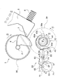
以上がプリンタ10の被記録媒体搬送経路の構成であり、以下、図3乃至図11を参照しつつ、給送装置1のより詳細な構成について説明する。ここで、図3は給送ローラ3およびホッパ5を斜め下から見た斜視図であり、図4は給送ローラ3(給送ローラ軸2)への動力伝達のオンおよびオフを行うクラッチ装置31の分解斜視図であり、図5は同組立図である。また、図6(a)、(b)はクラッチ部材43の動作原理を示す同クラッチ部材の断面図であり、図7乃至図11はクラッチ装置31の動作原理を示す同クラッチ装置の正面図(一部断面図)である。
【0036】
まず、図3を参照しつつ、ホッパ5を揺動駆動するカム機構について説明する。図3に示す如く、ホッパ5はその下部の両側端側に給送ローラ3側に向かって突出する様なカムフォロア7を有し、一方で給送ローラ軸2の両軸端側には、給送ローラ軸2の軸方向視において略扇形の形状をなし、カムフォロア7と係合するカム6が、給送ローラ軸2と一体的に形成されている。一方、ホッパ5の背面側には、ホッパ5を給送ローラ3に向けて揺動付勢する付勢手段としてのホッパばね8(図7参照)が設けられていて、ホッパ5は、該ホッパばね8によって常に給送ローラ3に向けて揺動付勢された状態となっている。そして、図3から明らかなように、給送ローラ3(給送ローラ軸2)の回転により、カム6とカムフォロア7との係合状態および非係合状態とが切り替わり、カム6がカムフォロア7を押し下げる係合状態(図3の状態)となることにより、ホッパ5が給送ローラ3から離間するようになっている。
【0037】
次に、図4乃至図6を参照しつつ、給送ローラ3(給送ローラ軸2)への動力伝達のオンおよびオフを行うクラッチ装置31の構成について説明する。
先ず、図4および図5において、クラッチ装置31は、図示しない駆動モータによって回動駆動される平歯車40を有し、従って該平歯車40が、クラッチ装置31への動力の入力部となっている。
【0038】
平歯車40は第1の歯車に相当するラチェット歯車41と一体的に形成されていて、該ラチェット歯車41には、該ラチェット歯車41の歯と噛合可能な歯部43aを円環形状の内部に有する、円環形状をなすクラッチ部材43が緩やかに嵌められる。クラッチ部材43は、その中心から偏倚した位置に軸受孔43bを有し、該軸受孔43bには、平歯車40とでクラッチ部材43を挟むように設けられる伝達歯車あるいは第2の歯車としての平歯車39の、回動中心から偏倚した位置に設けられる突起軸39aが嵌合するようになっている。そして、ラチェット歯車41にクラッチ部材43の歯部43aが噛合した状態となると、クラッチ部材43はラチェット歯車41と共に回動し、そしてこれにより、平歯車39も回動するようになっている。
【0039】
平歯車39には、給送ローラ3の回動軸である給送ローラ軸2の軸端に設けられた給送ローラ歯車35が噛合していて、従ってクラッチ部材43の歯部43aがラチェット歯車41に噛合した状態で平歯車40が回動すると、結果的に給送ローラ軸2に回動力が伝達され、以て給送ローラ3が回動するようになっている。
【0040】
また、以上から明かなように、クラッチ部材43の歯部43aがラチェット歯車41と噛合していない状態では、ラチェット歯車41はクラッチ部材43の円環の内部で空転するのみとなり、結果として平歯車40の回動力は、給送ローラ3へは伝達されない。尚、クラッチ装置31においては、図4および図5において図示しない軸体が、平歯車40、ラチェット歯車41、クラッチ部材43、平歯車39を挿通し、これにより、これら4つの回転体が同一の回転中心によって回動するようになっている。
【0041】
以上がクラッチ装置31の概要であり、以下、主にクラッチ部材31の動作原理について主として図6を参照しつつ、適宜図4をも参照しながら説明する。ここで、図6(a)は、上述したようにクラッチ部材43の歯部43aがラチェット歯車41と噛合して給送ローラ3へ回動力を伝達する状態を示していて、同図(b)は、クラッチ部材43の歯部43aがラチェット歯車41と噛合しておらず、給送ローラ3へ回動力を伝達しない状態を示している。
【0042】
図6(a)において、クラッチ部材43は軸受孔43bに突起軸39a(図5)が嵌合することにより、軸受孔43bを中心にして、図6の時計方向および反時計方向に揺動することができるようになっている。そして、揺動することにより、図6(a)に示す様な歯部43aとラチェット歯車41との噛合状態(歯車係合状態)となり、また、図6(b)に示す様な歯部43aとラチェット歯車41との非噛合状態(歯車非係合状態)となる。
【0043】
次に、クラッチ部材43にはばね掛止部43cが設けられ(図4も参照)、一方で平歯車39の側にもばね掛止部39bが設けられ(図4も参照)、これら2つのばね掛止部には、クラッチ部材付勢手段に相当する引っ張りコイルばね45が掛架されている。引っ張りコイルばね45は、歯部43aがラチェット歯車41と噛合する方向(ラチェット歯車41に圧接する方向)にクラッチ部材43を揺動付勢し、これにより、クラッチ部材43に外部から何らの力が作用していない状態では、歯部43aとラチェット歯車41とがしっかりと噛合するようになっている。そして、図6(a)から明かなように、ラチェット歯車41は本実施形態においては図6(a)の反時計回りに歯が傾いていて、また、歯部43aもこのように形成されたラチェット歯車41の歯と噛合するように形成されているので、ラチェット歯車41が図6(a)に示す反時計方向に回動すると、クラッチ部材43に回動力が伝達され、そして平歯車39も図6(a)の反時計方向に回動し、この結果、給送ローラ3が用紙Pを下流側に給送する方向(図2の時計方向)に回動する。
【0044】
次に、クラッチ部材43の外周部には、クラッチ係合部43dが形成されている。クラッチ係合部43dは、クラッチ部材43の外側に配置されているトリガーレバー51のレバー係合端53がクラッチ係合部43dの軌道経路を横切るように位置するとき、該レバー係合端53に係合する形状を有する。尚、ラチェット歯車41、クラッチ部材43、平歯車39及びトリガーレバー51は歯車装置を構成する。
【0045】
図7に示す如くトリガーレバー51は、レバー本体55と、レバー係合端53の反対端側に形成される案内板57とを備えて成り、案内板57はレバー本体55に対して垂直に形成され、またレバー本体55が案内板57のほぼ中程に位置するように形成されている。レバー本体55の中程にはレバー本体55の延びる方向に長穴59が形成されており、この長穴59に対して固定ピン61が挿入されている。レバー本体55は、固定ピン61が長穴59の両端に位置する範囲で矢印63で示す如くA−Bの方向へ移動可能であり、また固定ピン61が長穴59の案内板57側の端部に位置するときには固定ピン61を回動軸として回動可能である。長穴59の長さは、固定ピン61が長穴59の最もレバー係合端53側に位置するときには、レバー係合端53がクラッチ係合部43dに係合することはなく、固定ピン61が長穴59の最も案内板57側に位置するときには、レバー係合端53がクラッチ係合部43dに係合可能となるように設定されている。
【0046】
レバー本体55が案内板57に接続している地点74よりも上側の位置には引っ張りコイルバネ65の一端が接続されており、引っ張りコイルバネ65の他端は固定されている。また案内板57のレバー本体55が取り付けられている面と反対側には案内面67が形成されており、該案内面67には押圧突起69が押圧接触可能である。押圧突起69は回動円盤71の外周縁内側に、案内面67と平行に突出形成されており、図示しない駆動源からの駆動力により回動円盤71が符号73で示す矢印のD方向に回動するとき、押圧突起69が案内面57に接触し、更に矢印73のD方向に回動することにより、引っ張りコイルバネ65の引っ張り力に抗してトリガーレバー51を矢印63のB方向に、トリガーレバー51をクラッチ部材43の方向へ真っ直ぐに案内する図示しないガイドに沿って移動させることができる。尚、固定ピン61、引っ張りコイルバネ65、押圧突起69及び回動円盤71は、トリガーレバー制御装置を構成する。
【0047】
また押圧突起69が案内面57を矢印63のB方向に押し込む最終局面では、固定ピン61が長穴59の最も案内板57側に位置するまで、トリガーレバー51は、図示しないガイドに沿って矢印63のB方向に直線的に移動し、固定ピン61が長穴59の最も案内板57側に位置した以降は、図示しない上記ガイド作用が解除され、引っ張りコイルバネ65の引っ張り作用により、固定ピン61を回動中心としてレバー係合端53が上向きに移動するようになる。
【0048】
このようにトリガーレバー51は、回動円盤71の回動位置に応じて、レバー係合端53がクラッチ係合部43dと係合する「クラッチ係合状態」と、レバー係合端53がクラッチ係合部43dと係合しない「クラッチ非係合状態」とを切り替えることができるようになっている。
【0049】
図6に戻り、ラチェット歯車41が給送ローラ3に回動力を伝達する方向(図6(a)の反時計方向)に回動中にレバー係合端53がクラッチ部材43の外周部に進出すると(図6(a)に示すレバー係合端53の状態)、レバー係合端53とクラッチ係合部43dとが係合し、クラッチ部材43の回動が止められる。しかし、ラチェット歯車41は更に回動しようとするから、ラチェット歯車41の歯は、歯部43aを図6(a)の矢印に示す方向に押し退けようとする。ここで、クラッチ部材43は、軸受孔43bを中心に揺動可能に設けられているから、ラチェット歯車41の歯が歯部43aを図6(a)の矢印に示す方向に押し上げようとする力によって、クラッチ部材43は引っ張りコイルばね45の付勢力に抗して揺動し、この結果、図6(b)に示す様なラチェット歯車41と歯部43aとの非噛合状態となる。
【0050】
以上がクラッチ部材43の動作原理であり、以下、給送ローラ3、ホッパ5の動きと共に、クラッチ装置31全体の動作原理について説明する。尚、以下では、ラチェット歯車41と歯部43aとが噛合し、これによって図示しない駆動モータから給送ローラ3に回動力が伝達される状態を、クラッチ装置31の「稼働状態」と言うこととする。
【0051】
先ず、図7は、給送装置1が給送待機状態から、給送動作に移った直後の状態を示している。この状態では、給送ローラ3は図示するように側面視略D形の形状における平坦部をホッパ5に対向させた状態となっていて(図2に示す状態)、ホッパ5は、ホッパばね8のばね力に抗して給送ローラ3から離間した状態にある。より詳しくは、図3を参照しつつ説明したカム6とカムフォロア7とが係合した状態にあり、カム6が、カムフォロア7を介してホッパ5を下方に押し下げた状態となっている。従ってこの状態では、ホッパ5上にセットされた用紙Pは、給送ローラ3には圧接していない。
【0052】
そして、給送動作の開始時には、図示しない駆動源の駆動力により回動円盤71が矢印73のC方向に回動しているため、引っ張りコイルバネ65の引っ張り作用でレバー係合端53がクラッチ部材43の外周部から退避している。従ってラチェット歯車41と歯部43aとが引っ張りコイルばね45の付勢力によって噛合状態となり、クラッチ装置31が稼働状態となる。尚、図7乃至図9において符号▲3▼、▲4▼、▲5▼を付して実線で示す矢印は、それぞれ給送ローラ3(即ち、給送ローラ軸2、給送ローラ歯車35、カム6)、平歯車39、クラッチ部材43のそれぞれの回動方向を示すと同時に、当該実線で示す矢印は、これら回動体が、クラッチ装置31が稼働状態となり、図示しない駆動モータの駆動力によって回動する状態を示している。また、符号▲1▼および▲2▼で示す矢印は、ホッパ5が揺動可能な方向を示している。
【0053】
次に、図7に示す状態から符号▲6▼で示す方向にラチェット歯車41が回動すると、図7から図8に示す変化のように、カム6とカムフォロア7との係合が解かれ、ホッパ5は、ホッパばね8の付勢力によって給送ローラ3に圧接する方向(図7の符号▲1▼で示す方向)に揺動する。これにより、ホッパ5上にセットされた用紙Pが給送ローラ3に圧接し、給送ローラ3の回動と共に、最上位の用紙Pの給送が開始される。またこの時、回動円盤71が矢印73のD方向に一定量だけ回動することで、押圧突起69が案内面67に当接して案内板57を符号63で示す矢印のB方向に押し込み、レバー係合端53がクラッチ部材43側へ進出した状態となる(図8参照)。尚このとき、固定ピン61が長穴59の最も案内板57側に位置する状態となる。
【0054】
次に、ラチェット歯車41が更に回動すると、図9に示すようにカム6とカムフォロア7とが再び係合を開始して、ホッパ5を給送ローラ3から離間する方向(図7の符号▲2▼で示す方向)に揺動させると共に、クラッチ係合部43dとレバー係合端53とが係合する。そして、図9に示す状態からラチェット歯車41が更に回動すると、ラチェット歯車41の歯が歯部43aを押し退け、これにより、クラッチ部材43は図9の矢印▲7▼で示す方向に揺動する。
【0055】
この結果、図10に示すように歯部43aがラチェット歯車41の歯から外れ、クラッチ装置31は非稼働状態となる。しかしこの状態では、歯部43aが、ラチェット歯車41によって押し退けられるようにしてラチェット歯車41の歯から遠ざかる為、ラチェット歯車41の歯と接触するかしないか、いわばぎりぎりの状態にあり、場合によっては、ラチェット歯車41の回動に従って異音(接触音)が発生する状態となる。
【0056】
そこで本発明では以下の動作により、歯部43aがラチェット歯車41の歯から完全に外れる状態とすることができる。即ち、図10に示す状態の直後に回動円盤71を矢印73のD方向に更に回動させる。この動作により押圧突起69が案内板57を矢印63で示す矢印のB方向へ更に押し込もうとするが、既に固定ピン61が長穴59の最も案内板57側に位置しているため、レバー係合端53はそれ以上B方向に移動することができない。
【0057】
一方押圧突起69は、レバー本体55が案内板57に接続している地点74よりも図11において下側の地点において案内面67に当接するようになるため、引っ張りコイルバネ65により案内板57の上端側を引っ張る力と相まって、固定ピン61を回動軸としてトリガーレバー51が回動するようにモーメントが働き、その結果、レバー係合端53が矢印75で示す方向に回動するようになる。これにより、レバー係合端53がクラッチ係合部43dを押し上げて、図11に示すように歯部43aがラチェット歯車41から更に遠ざかり、前述した様な歯部43aがラチェット歯車41の歯と接触するかしないかの状態が解消され、ラチェット歯車41が回動しても、異音(接触音)が発生しない状態となる。
【0058】
上記実施の形態では、カム6が給送ローラ軸2に設けられているが、カム2は第2のギア及び伝達ギアである平歯車39に設けるようにしてもよいし、平歯車39と給送ローラ歯車35との間に給送ローラ軸へ回動力を伝達するために追加的に第3のギアを設け、この第3のギアの回動軸に対して設けるようにしてもよい。尚、上記実施の形態の給送ローラ歯車35は、この第3の歯車の一例でもある。
【図面の簡単な説明】
【図1】 本発明の給送装置を適用したインクジェットプリンタの外観斜視図。
【図2】 本発明の給送装置を適用したインクジェットプリンタの側断面概略図。
【図3】 給送ローラおよびホッパを斜め下から見た外観斜視図。
【図4】 クラッチ装置の分解斜視図。
【図5】 クラッチ装置の組立図。
【図6】 クラッチ部材の動作原理を示す、同クラッチ部材の断面図。
【図7】 クラッチ装置の動作原理を示すクラッチ装置の正面図(一部断面図)。
【図8】 クラッチ装置の動作原理を示すクラッチ装置の正面図(一部断面図)。
【図9】 クラッチ装置の動作原理を示すクラッチ装置の正面図(一部断面図)。
【図10】 クラッチ装置の動作原理を示すクラッチ装置の正面図(一部断面図)。
【図11】 クラッチ装置の動作原理を示すクラッチ装置の正面図(一部断面図)。
【符号の説明】
1 給送装置、2 給送ローラ軸、3 給送ローラ、 4 リタードローラ
5 ホッパ、6 カム、7 カムフォロア、8 ホッパばね、9 戻しレバー、
10 インクジェットプリンタ、12 メインフレーム、13 駆動プーリ、
14 従動プーリ、15 案内、17 搬送ローラ、18 無端ベルト、
19 被記録媒体検出、21 搬送従動ローラホルダ、23 キャリッジ、
24 インクカートリッジ、25 記録ヘッド、27 プラテン、
28 インクカートリッジ、29 排出ローラ、30 補助ローラ、
31 クラッチ装置、32 キャリッジガイド軸、35 給送ローラ歯車、
39 平歯車、39a 突起軸、39b ばね掛止部、40 平歯車、
41 ラチェット歯車、43 クラッチ部材、43a 歯部、43b 軸受孔、
43c ばね掛止部、43d クラッチ係合部、45 引っ張りコイルばね、
51 トリガーレバー、53 レバー係合端、55 レバー本体、57 案内板
59 長穴、61 固定ピン、63 矢印、65 引っ張りコイルバネ、
67 案内面、69 押圧突起、71 回動円盤、73 矢印、
74 レバー本体が案内板に接続している地点、75 矢印、P 用紙[0001]
BACKGROUND OF THE INVENTION
The present invention relates to a feeding device that feeds a recording medium and a recording device that includes the feeding device. The present invention further relates to a liquid ejecting apparatus such as an ink jet recording apparatus that ejects a liquid such as ink from a head to eject the liquid onto an ejected medium.
[0002]
Here, the liquid ejecting apparatus uses an ink jet recording head, and is not limited to a recording apparatus such as a printer, a copying machine, and a facsimile machine that records ink on a recording medium by discharging ink from the recording head. It includes a device that ejects a liquid corresponding to the application from a liquid ejecting head corresponding to the recording head to an ejected medium corresponding to a recording medium and adheres the liquid to the ejected medium.
[0003]
In addition to the recording head, as a liquid ejecting head, a color material ejecting head used for manufacturing a color filter such as a liquid crystal display, and an electrode material (conductive paste) used for forming an electrode such as an organic EL display or a surface emitting display (FED) Examples thereof include an ejection head, a bioorganic matter ejection head used for biochip production, and a sample ejection head as a precision pipette.
[0004]
[Prior art]
One of the recording devices is an ink jet printer (hereinafter referred to as “printer”), and some of the printers include a feeding device (ASF) that feeds printing paper one by one to a recording head unit. In such a feeding apparatus, a feeding roller for feeding the printing paper is provided, and a driving source of the feeding roller is a feeding roller for feeding the printing paper to the recording head unit for cost reduction. In general, it is also used as a drive source such as
[0005]
Here, when power is transmitted from the drive motor to the conveying roller and the feeding roller, for example, when the printing paper is conveyed by the conveying roller, it is necessary to stop the rotation of the feeding roller. It is also necessary to perform forward and reverse bidirectional rotational driving. Therefore, from this point of view, a clutch device that turns on and off power transmission from the drive motor to the feeding roller is required.
[0006]
By the way, the clutch device as described above has a ratchet gear that is always rotationally driven by a drive motor, and a tooth portion that can mesh with the ratchet gear, and the tooth portion and the ratchet gear by swinging. There is one constituted by a clutch member that switches between the engaged state and the disengaged state.
[0007]
However, when the ratchet gear and the tooth portion release the engagement state, if the release operation is not performed reliably, the ratchet gear and the tooth portion are in slight contact with each other, and abnormal noise is generated during driving. (Contact sound) will be generated, and an undesirable state will be caused.
[0008]
[0009]
[0010]
[Patent Document 1]
JP-A-3-264430
[Patent Document 2]
JP-A-6-219595
[Patent Document 3]
JP 2001-341871 A
[0011]
[Problems to be solved by the invention]
The present invention has been made in view of such a situation, and an object of the present invention is to reliably release the engagement state between the gear and the tooth portion that can mesh with the gear, thereby making noise during driving. It is to prevent it from occurring.
[0012]
[Means for Solving the Problems]
In order to solve the above-described problem, a feeding device according to a first aspect of the present invention is provided on a feeding roller shaft that is rotationally driven, and provided above a feeding roller that feeds a recording medium. A hopper that is provided so as to be able to oscillate about the oscillating fulcrum, and that presses the recording medium against the feeding roller, and an urging force that urges the hopper toward the feeding roller. And a cam for separating the hopper from the feed roller against the biasing means by engaging with a cam follower provided on the hopper and a power from the drive motor to the feed roller A gear device, wherein the gear device has a ratchet gear that is rotationally driven by the drive motor, a tooth portion that can mesh with the ratchet gear, and is swingable. By swinging A clutch member that switches a gear engagement state and a gear non-engagement state between the tooth portion and the ratchet gear, holds the clutch member in a swingable manner, and the clutch member is in the gear engagement state. In this case, the clutch engagement between the transmission gear that receives the power from the clutch member and rotates together with the clutch member to transmit the rotational force to the feeding roller shaft, and the clutch engaging portion provided in the clutch member. An engagement state and a clutch non-engagement state are provided so as to be switchable, and the clutch member is shaken by the clutch member and the transmission gear changing from the clutch non-engagement state to the clutch engagement state while the transmission gear is rotating. A trigger lever that switches the clutch member from the gear engaged state to the gear non-engaged state by moving the clutch member; A trigger lever control device that performs control so as to switch between a latch non-engagement state and a clutch engagement state, and the cam is configured to feed the feed roller from the feed roller shaft, the rotation shaft of the transmission gear, or the transmission gear. The trigger lever is provided at one of the rotating shafts of the gear provided in the middle of the transmission mechanism for transmitting the rotational force to the shaft, and the trigger lever is engageable with the clutch engaging portion in the clutch engaged state. The trigger lever control device shifts the lever engaging end to a position engageable with the clutch engaging portion, and the clutch engaging portion engages with the lever engaging end. The lever engaging end is controlled to shift in a direction opposite to the rotation direction of the clutch member when the tooth portion of the clutch member is disengaged from the gear. .
[0013]
According to the first aspect of the present invention, the rotation shaft of the feeding roller is rotationally driven by the transmission gear, and power is transmitted to the transmission gear in the order of the ratchet gear and the clutch member. Yes. On the other hand, a cam is provided on any of the feed roller shaft, the rotation shaft of the transmission gear, or the rotation shaft of the gear provided in the middle of the transmission mechanism for transmitting the rotational force from the transmission gear to the feed roller shaft. The cam follower is in pressure contact. The cam follower is provided in the hopper, and the cam functions to separate the hopper from the feeding roller. In addition, a trigger lever that swings the clutch member to switch the clutch member from the gear engaged state to the gear disengaged state is provided, and the trigger lever control device switches the trigger lever to the clutch non-engaged state and the clutch engaged state. Can be controlled. The trigger lever control device first moves the lever engaging end to a position where it can engage with the clutch engaging portion, and the clutch engaging portion engages with the lever engaging end, and the tooth portion of the clutch member disengages from the ratchet gear. At this stage, the lever engagement end is controlled so as to shift to the direction opposite to the rotation direction of the clutch member, that is, the direction opposite to the direction in which the clutch engagement portion has rotated. Thereby, since the tooth part provided in the clutch member is completely separated from the ratchet gear, it is possible to prevent the generation of abnormal noise or the like.
[0014]
The feeding device according to a second aspect of the present invention is the feeding device according to the first aspect, wherein the trigger lever includes a lever main body having a lever engaging end formed at a tip thereof, and the lever engaging end of the lever main body. A guide plate connected to the lever body on a side substantially perpendicular to the lever body, a slot formed to extend in the longitudinal direction of the lever body, and a guide plate on the side opposite to the lever body. And the trigger lever control device further includes a trigger engaging device that engages the clutch engaging portion with the lever engaging end when viewed from the point where the lever main body is connected to the guide plate. A tension coil spring, one end of which is connected to the guide plate, is inserted so as to be relatively movable in the elongated hole, and the trigger lever is allowed to move between the clutch engaged state and the clutch non-engaged state. And the longest hole A fixed pin that functions as a pivot shaft of the trigger lever when positioned on the guide plate side, a rotary disk provided adjacent to the guide plate, and protrudes in parallel with the guide surface from the rotary disk, A pressing protrusion capable of shifting the lever engagement end to the clutch engagement state by pushing the guide plate against the guide surface by rotation of a rotation disk, and the fixing pin Only when the elongated hole is located closest to the guide plate, the lever engaging end faces the rotating direction of the clutch member by rotating the trigger lever with the pressing protrusion as the rotation center. It is characterized by shifting in the direction to do.
[0015]
According to the second aspect of the present invention, the rotating disk rotates when the clutch engaging portion does not rotate to the position facing the lever engaging portion, so that the pressing protrusion moves the guide plate to the clutch member side. The lever engaging portion advances. When the clutch member rotates, it engages with the lever engaging portion, the tooth portion of the clutch member is pushed up by the teeth of the ratchet gear, and the engagement therebetween is released. When the rotating disk further rotates in this state, the fixing pin is located closest to the guide plate of the elongated hole, so that the lever engaging end does not move further to the clutch member side and the fixing pin rotates. The trigger lever as a whole rotates. As a result, since the lever engaging portion shifts the clutch engaging portion in a direction opposite to the rotation direction of the clutch member, even if the tooth portion of the clutch member moves away from the teeth of the ratchet gear and the ratchet gear rotates, An abnormal sound (contact sound) is not generated.
[0016]
The feeding device according to a third aspect of the present invention is the feeding device according to the second aspect, wherein when the fixing pin is located closest to the guide plate of the elongated hole, the pressing protrusion is the lever body. The tension coil spring is located on the side opposite to the side connected to the guide plate when viewed from the point connected to the guide plate.
[0017]
According to the third aspect of the present invention, the pulling action of the tension coil spring and the action of the pressing projection pressing the portion of the guide surface opposite to the side to which the tension coil spring is connected work. The moment that the trigger lever rotates is applied. Thereby, the lever engaging portion generates a force for shifting the clutch engaging portion in a direction opposite to the rotation direction of the clutch member.
[0018]
The recording apparatus of the present invention includes a recording head for recording on a recording medium, a carriage provided at the bottom of the recording head and reciprocally movable in the main scanning direction, and any one of the first to third aspects. And a feeding device according to the aspect. According to the present invention, it is possible to provide a recording apparatus that does not generate abnormal noise (contact sound).
[0019]
The clutch device of the present invention is a clutch device that turns on and off power transmission from a first gear that is rotationally driven by a drive motor to a second gear that is transmitted power by the first gear. A cam provided on either the rotary shaft of the second gear or the rotary shaft of a third gear capable of transmitting drive from the second gear, and a cam follower provided so as to be in pressure contact with the cam A tooth portion that can mesh with the first gear, and is provided so as to be able to swing, and by swinging, the gear engagement state between the tooth portion and the first gear and the gear non-engagement. A clutch member for switching the engagement state, clutch member urging means for oscillating and urging the clutch member in a direction in which the tooth portion engages with the first gear, and a clutch engagement portion provided in the clutch member Clutch engagement state and clutch The clutch member is swingable when the clutch member and the second gear are turned, and the clutch member is changed from the clutch non-engagement state to the clutch engagement state. A trigger lever that switches the clutch member from the gear engaged state to the gear non-engaged state, and a trigger lever control device that controls the trigger lever to switch between the clutch non-engaged state and the clutch engaged state. The second gear holds the clutch member in a swingable manner, and rotates together with the clutch member by receiving power from the clutch member when the clutch member is in the gear engagement state. The trigger lever includes a lever engaging end engageable with the clutch engaging portion in the clutch engaged state, The lever control device shifts the lever engaging end to a position where the lever engaging end can be engaged with the clutch engaging portion, and the clutch engaging portion engages with the lever engaging end to move the clutch from the first gear. The lever engaging end is controlled to move in a direction opposite to the rotation direction of the clutch member when the tooth portion of the member is disengaged.
[0020]
According to the present invention, a trigger lever that swings the clutch member to switch the clutch member from the gear engaged state to the gear disengaged state is provided, and the trigger lever control device disengages the trigger lever from the clutch disengaged state and the clutch engaged state. It can be controlled to switch to a state. The trigger lever control device first moves the lever engaging end to a position where it can engage with the clutch engaging portion, and the clutch engaging portion engages with the lever engaging end, and the tooth portion of the clutch member disengages from the ratchet gear. At this stage, the lever engagement end is controlled so as to shift to the direction opposite to the rotation direction of the clutch member, that is, the direction opposite to the direction in which the clutch engagement portion has rotated. Thereby, since the tooth part provided in the clutch member is completely separated from the ratchet gear, it is possible to prevent the generation of abnormal noise or the like.
[0021]
A feeding device according to another aspect of the present invention is provided on a feeding roller shaft that is rotationally driven, and swings around a feeding roller that feeds an ejected medium and a swing fulcrum provided above. A hopper that is movably provided and oscillates to press the medium to be ejected against the feeding roller, a biasing means that biases the hopper toward the feeding roller, and the hopper A feed comprising: a cam for engaging the cam follower to separate the hopper from the feed roller against the biasing means; and a gear device for transmitting power from a drive motor to the feed roller. The gear device has a ratchet gear that is rotationally driven by the drive motor, and a tooth portion that can mesh with the ratchet gear, and is provided so as to be able to swing, and swings. The tooth part and the ratchet A clutch member that switches between a gear engagement state and a gear non-engagement state with a vehicle; and when the clutch member is swingably held and the clutch member is in the gear engagement state, A clutch engagement state and a clutch non-engagement of a transmission gear that transmits power to the feeding roller shaft by receiving power and rotating together with the clutch member, and a clutch engaging portion provided in the clutch member The clutch member and the transmission gear are turned to move from the clutch non-engaged state to the clutch engaged state while the clutch member and the transmission gear are rotating, so that the clutch member is swung to move the clutch member. A trigger lever that switches from the gear engaged state to the gear disengaged state; and A trigger lever control device that controls to switch to the engaged state, and the cam transmits rotational force from the feeding roller shaft, the rotation shaft of the transmission gear, or the transmission gear to the feeding roller shaft. The trigger lever is provided on one of the rotation shafts of a gear provided in the middle of the transmission mechanism, and the trigger lever includes a lever engagement end that can be engaged with the clutch engagement portion in the clutch engagement state. The control device shifts the lever engaging end to a position where the lever engaging end can be engaged with the clutch engaging portion, and the clutch engaging portion engages with the lever engaging end so that the ratchet gear engages with the teeth of the clutch member. The lever engaging end is controlled so as to shift in a direction opposite to the rotation direction of the clutch member when the portion is disengaged.
[0022]
DETAILED DESCRIPTION OF THE INVENTION
Hereinafter, embodiments of the present invention will be described with reference to the drawings. Hereinafter, a schematic configuration of an ink jet printer (hereinafter referred to as “printer”) 10 which is an example of a recording apparatus or a liquid ejecting apparatus according to an embodiment of the invention will be described with reference to FIGS. 1 and 2. Here, FIG. 1 is an external perspective view of the main body of the printer 10 (with a cover member constituting the external appearance removed), and FIG. 2 is a schematic sectional side view of the same. In the following, the right back side (the rear side of the printer 10) in FIG. 1 is referred to as “upstream side” (upstream side of the recording medium conveyance path), and the left front side (the front side of the printer 10) in FIG. It is referred to as “downstream side” (downstream side of the recording medium conveyance path).
[0023]
As shown in FIG. 1, the
[0024]
A feeding
[0025]
The
[0026]
The
[0027]
The return lever 9 is disposed in the vicinity of the lower end portion of the
[0028]
Next, a
[0029]
Here, the conveyance driven
[0030]
Next, a recording medium detector comprising a sensor
[0031]
Subsequently, the
[0032]
In FIG. 1, a driven
[0033]
Next, referring back to FIG. 2, a discharge section is provided downstream from the
[0034]
By the way, the
[0035]
The above is the configuration of the recording medium conveyance path of the
[0036]
First, a cam mechanism that drives the
[0037]
Next, the configuration of the
4 and 5, the
[0038]
The
[0039]
The
[0040]
Further, as apparent from the above, in a state where the
[0041]
The above is the outline of the
[0042]
In FIG. 6A, the
[0043]
Next, the
[0044]
Next, a
[0045]
As shown in FIG. 7, the
[0046]
One end of the
[0047]
In the final phase in which the
[0048]
As described above, the
[0049]
Returning to FIG. 6, the
[0050]
The above is the operation principle of the
[0051]
First, FIG. 7 shows a state immediately after the
[0052]
At the start of the feeding operation, the
[0053]
Next, when the
[0054]
Next, when the
[0055]
As a result, as shown in FIG. 10, the
[0056]
Therefore, in the present invention, the
[0057]
On the other hand, the pressing
[0058]
In the above-described embodiment, the
[Brief description of the drawings]
FIG. 1 is an external perspective view of an ink jet printer to which a feeding device of the present invention is applied.
FIG. 2 is a schematic side sectional view of an ink jet printer to which the feeding device of the present invention is applied.
FIG. 3 is an external perspective view of a feeding roller and a hopper as viewed obliquely from below.
FIG. 4 is an exploded perspective view of the clutch device.
FIG. 5 is an assembly drawing of the clutch device.
FIG. 6 is a cross-sectional view of the clutch member showing the operating principle of the clutch member.
FIG. 7 is a front view (partially sectional view) of the clutch device showing an operation principle of the clutch device.
FIG. 8 is a front view (partial cross-sectional view) of the clutch device illustrating the operating principle of the clutch device.
FIG. 9 is a front view of the clutch device showing a principle of operation of the clutch device (partial cross-sectional view).
FIG. 10 is a front view (partially sectional view) of the clutch device showing an operation principle of the clutch device.
FIG. 11 is a front view of the clutch device showing a principle of operation of the clutch device (partial cross-sectional view).
[Explanation of symbols]
1 feeding device, 2 feeding roller shaft, 3 feeding roller, 4 retard roller
5 hopper, 6 cam, 7 cam follower, 8 hopper spring, 9 return lever,
10 inkjet printer, 12 main frame, 13 drive pulley,
14 driven pulley, 15 guide, 17 transport roller, 18 endless belt,
19 Recording medium detection, 21 Conveyance driven roller holder, 23 Carriage,
24 ink cartridge, 25 recording head, 27 platen,
28 ink cartridges, 29 discharge rollers, 30 auxiliary rollers,
31 clutch device, 32 carriage guide shaft, 35 feed roller gear,
39 spur gear, 39a protrusion shaft, 39b spring latch, 40 spur gear,
41 ratchet gear, 43 clutch member, 43a tooth portion, 43b bearing hole,
43c spring latching part, 43d clutch engaging part, 45 tension coil spring,
51 Trigger lever, 53 Lever engaging end, 55 Lever body, 57 Guide plate
59 long hole, 61 fixing pin, 63 arrow, 65 tension coil spring,
67 guide surface, 69 pressing projection, 71 rotating disk, 73 arrow,
74 Point where the lever body is connected to the guide plate, 75 arrow, P paper
Claims (4)
上方に設けられた揺動支点を中心に揺動可能に設けられ、揺動することにより、前記給送ローラに被記録媒体を圧接させるホッパと、
該ホッパを前記給送ローラに向けて付勢する付勢手段と、
前記ホッパに設けられたカムフォロアと係合することにより、前記付勢手段に抗して前記ホッパを前記給送ローラから離間させるカムと、
駆動モータから前記給送ローラに動力を伝達する歯車装置と、を備えた給送装置であって、
前記歯車装置が、前記駆動モータによって回動駆動されるラチェット歯車と、
前記ラチェット歯車と噛合可能な歯部を有し、且つ、揺動可能に設けられ、揺動することにより、前記歯部と前記ラチェット歯車との歯車係合状態および歯車非係合状態を切り替えるクラッチ部材と、
前記クラッチ部材を揺動可能に保持し、且つ、前記クラッチ部材が前記歯車係合状態にある際に、前記クラッチ部材から動力を受けて前記クラッチ部材と共に回動することによって前記給送ローラ軸に回動力を伝達する伝達歯車と、
前記クラッチ部材に設けられたクラッチ係合部とのクラッチ係合状態およびクラッチ非係合状態とを切り替え可能に設けられ、前記クラッチ部材および前記伝達歯車が回動中において前記クラッチ非係合状態から前記クラッチ係合状態となることにより、前記クラッチ部材を揺動させて当該クラッチ部材を前記歯車係合状態から前記歯車非係合状態に切り替えるトリガーレバーと、
前記トリガーレバーをクラッチ非係合状態及びクラッチ係合状態に切り替えるように制御するトリガーレバー制御装置とを備え、
前記カムは、前記給送ローラ軸、前記伝達ギアの回動軸または前記伝達ギアから前記給送ローラ軸へ回動力を伝達する伝達機構の途中に設けられるギアの回動軸のいずれかに設けられ、
前記トリガーレバーは、前記クラッチ係合状態において前記クラッチ係合部と係合可能なレバー係合端を備え、
前記トリガーレバー制御装置は、前記レバー係合端を前記クラッチ係合部と係合可能な位置へ移行し、前記クラッチ係合部が前記レバー係合端に係合して前記ラチェット歯車から前記クラッチ部材の歯部が外れた段階で、前記レバー係合端を前記クラッチ部材の回動方向と対向する方向へ移行するように制御すると共に、
前記トリガーレバーは、
先端に前記レバー係合端が形成されるレバー本体と、
前記レバー本体の前記レバー係合端とは反対側にレバー本体とほぼ垂直に接続される案内板と、
前記レバー本体に対してその長手方向に延びるように形成される長穴と、
前記案内板の前記レバー本体とは反対側に形成される案内面とを有し、
前記トリガーレバー制御装置は更に、
前記レバー本体が案内板に接続している地点から見て、レバー係合端にクラッチ係合部が係合する方向側の案内板上に一端が接続される引っ張りコイルバネと、
前記長穴内で相対的に移動可能に挿入され、前記トリガーレバーが前記クラッチ係合状態とクラッチ非係合状態との間で移動することを許容し、前記長穴の最も案内板側に位置しているときにトリガーレバーの回動軸として機能する固定ピンと、
前記案内板に隣接して設けられる回動円盤と、
前記回動円盤から前記案内面と平行に突出し、前記回動円盤の回動により前記案内面に当接して前記案内板を押し込むことにより、前記レバー係合端を前記クラッチ係合状態に移行させることが可能な押圧突起とを備え、
前記固定ピンが前記長穴の最も案内板側に位置しているときにのみ、前記押圧突起を回動中心として前記トリガーレバーが回動することにより、前記レバー係合端が前記クラッチ部材の回動方向と対向する方向へ移行するようになっていることを特徴とする給送装置。A feed roller that is provided on a rotation-driven feed roller shaft and feeds a recording medium;
A hopper provided so as to be able to swing around a swing fulcrum provided above, and by pressing the recording medium against the feeding roller by swinging;
Biasing means for biasing the hopper toward the feeding roller;
A cam for separating the hopper from the feeding roller against the biasing means by engaging with a cam follower provided in the hopper;
A gear device that transmits power from a drive motor to the feeding roller, and a feeding device comprising:
The gear device is a ratchet gear that is rotationally driven by the drive motor;
A clutch that has a tooth portion that can mesh with the ratchet gear, is provided so as to be able to swing, and switches between a gear engagement state and a gear non-engagement state between the tooth portion and the ratchet gear by swinging. Members,
When the clutch member is held so as to be swingable and the clutch member is in the gear engagement state, the clutch member receives power from the clutch member and rotates together with the clutch member. A transmission gear for transmitting rotational power;
A clutch engagement state and a clutch non-engagement state with a clutch engagement portion provided on the clutch member are provided so as to be switchable, and the clutch member and the transmission gear are rotated from the clutch non-engagement state while rotating. A trigger lever that swings the clutch member to switch the clutch member from the gear engaged state to the gear non-engaged state by being in the clutch engaged state;
A trigger lever control device for controlling the trigger lever to switch between a clutch non-engagement state and a clutch engagement state,
The cam is provided on any one of the feeding roller shaft, the rotation shaft of the transmission gear, or the rotation shaft of a gear provided in the middle of a transmission mechanism that transmits rotational force from the transmission gear to the feeding roller shaft. And
The trigger lever includes a lever engagement end that can be engaged with the clutch engagement portion in the clutch engagement state,
The trigger lever control device shifts the lever engaging end to a position where the lever engaging end can be engaged with the clutch engaging portion, and the clutch engaging portion engages with the lever engaging end to release the clutch from the ratchet gear. At the stage where the tooth portion of the member is detached, the lever engaging end is controlled to move in a direction opposite to the rotation direction of the clutch member, and
The trigger lever is
A lever body having the lever engaging end formed at the tip;
A guide plate connected substantially perpendicularly to the lever body on the side opposite to the lever engaging end of the lever body;
An elongated hole formed to extend in the longitudinal direction of the lever body;
A guide surface formed on the opposite side of the guide plate from the lever body,
The trigger lever control device further includes:
A tension coil spring having one end connected on the guide plate on the direction side in which the clutch engaging portion is engaged with the lever engaging end when viewed from the point where the lever main body is connected to the guide plate,
It is inserted so as to be relatively movable in the elongated hole, and the trigger lever is allowed to move between the clutch engaged state and the clutch non-engaged state, and is located closest to the guide plate of the elongated hole. A fixed pin that functions as the pivot axis of the trigger lever when
A rotating disk provided adjacent to the guide plate;
The lever engagement end shifts to the clutch engagement state by projecting parallel to the guide surface from the rotating disk and pressing the guide plate by contacting the guide surface by the rotation of the rotating disk. A pressing protrusion capable of
Only when the fixing pin is located closest to the guide plate of the elongated hole, the trigger lever is rotated about the pressing projection as a rotation center, so that the lever engaging end is rotated by the clutch member. A feeding device characterized in that it moves in a direction opposite to the moving direction.
該記録ヘッドを底部に備え、主走査方向に往復動可能に設けられるキャリッジと、
請求項1又は2に記載の給送装置とを備えていることを特徴とする記録装置。A recording head for recording on a recording medium;
A carriage provided at the bottom of the recording head and provided to be reciprocable in the main scanning direction;
A recording apparatus comprising: the feeding apparatus according to claim 1.
前記第2の歯車の回動軸または第2の歯車から駆動伝達可能な第3の歯車の回動軸のいずれかに設けられるカムと、
該カムに圧接するように設けられるカムフォロアと、
前記第1の歯車と噛合可能な歯部を有し、且つ、揺動可能に設けられ、揺動することにより、前記歯部と前記第1の歯車との歯車係合状態および歯車非係合状態を切り替えるクラッチ部材と、
該クラッチ部材を前記歯部が前記第1の歯車と係合する方向に揺動付勢するクラッチ部材付勢手段と、
前記クラッチ部材に設けられたクラッチ係合部とのクラッチ係合状態およびクラッチ非係合状態とを切り替え可能に設けられ、前記クラッチ部材および前記第2の歯車が回動中において前記クラッチ非係合状態から前記クラッチ係合状態となることにより、前記クラッチ部材を揺動させて当該クラッチ部材を前記歯車係合状態から前記歯車非係合状態に切り替えるトリガーレバーと、
前記トリガーレバーをクラッチ非係合状態及びクラッチ係合状態に切り替えるように制御するトリガーレバー制御装置とを備え、
前記第2の歯車は、前記クラッチ部材を揺動可能に保持し、且つ、前記クラッチ部材が前記歯車係合状態にある際に、前記クラッチ部材から動力を受けて前記クラッチ部材と共に回動し、
前記トリガーレバーは、前記クラッチ係合状態において、前記クラッチ係合部と係合可能なレバー係合端を備え、前記トリガーレバー制御装置は、前記レバー係合端を前記クラッチ係合部と係合可能な位置へ移行し、前記クラッチ係合部が前記レバー係合端に係合して前記第1の歯車から前記クラッチ部材の歯部が外れた段階で、前記レバー係合端を前記クラッチ部材の回動方向と対向する方向へ移行するように制御することを特徴とするクラッチ装置。A clutch device for turning on and off power transmission from a first gear rotated by a drive motor to a second gear to which power is transmitted by the first gear;
A cam provided on either the rotation shaft of the second gear or the rotation shaft of a third gear capable of transmitting drive from the second gear;
A cam follower provided to be in pressure contact with the cam;
The toothed portion that can mesh with the first gear, and is provided so as to be able to swing. By swinging, the gear engagement state and the gear non-engagement between the toothed portion and the first gear A clutch member for switching the state;
Clutch member biasing means for swinging and biasing the clutch member in a direction in which the tooth portion engages with the first gear;
A clutch engagement state and a clutch non-engagement state with a clutch engagement portion provided on the clutch member are provided so as to be switchable, and the clutch member and the second gear are not engaged while the clutch member and the second gear are rotating. A trigger lever for switching the clutch member from the gear engaged state to the gear non-engaged state by swinging the clutch member by becoming a clutch engaged state from a state;
A trigger lever control device for controlling the trigger lever to switch between a clutch non-engagement state and a clutch engagement state,
The second gear holds the clutch member in a swingable manner, and rotates together with the clutch member by receiving power from the clutch member when the clutch member is in the gear engagement state.
The trigger lever includes a lever engaging end engageable with the clutch engaging portion in the clutch engaged state, and the trigger lever control device engages the lever engaging end with the clutch engaging portion. When the clutch engaging portion engages with the lever engaging end and the tooth portion of the clutch member is disengaged from the first gear, the lever engaging end is moved to the clutch member. The clutch device is controlled so as to shift in a direction opposite to the rotation direction.
Priority Applications (1)
| Application Number | Priority Date | Filing Date | Title |
|---|---|---|---|
| JP2003019386A JP3965574B2 (en) | 2003-01-28 | 2003-01-28 | Feed device, recording device, and clutch device |
Applications Claiming Priority (1)
| Application Number | Priority Date | Filing Date | Title |
|---|---|---|---|
| JP2003019386A JP3965574B2 (en) | 2003-01-28 | 2003-01-28 | Feed device, recording device, and clutch device |
Publications (2)
| Publication Number | Publication Date |
|---|---|
| JP2004231326A JP2004231326A (en) | 2004-08-19 |
| JP3965574B2 true JP3965574B2 (en) | 2007-08-29 |
Family
ID=32949259
Family Applications (1)
| Application Number | Title | Priority Date | Filing Date |
|---|---|---|---|
| JP2003019386A Expired - Fee Related JP3965574B2 (en) | 2003-01-28 | 2003-01-28 | Feed device, recording device, and clutch device |
Country Status (1)
| Country | Link |
|---|---|
| JP (1) | JP3965574B2 (en) |
Families Citing this family (1)
| Publication number | Priority date | Publication date | Assignee | Title |
|---|---|---|---|---|
| JP2008273677A (en) * | 2007-04-27 | 2008-11-13 | Seiko Epson Corp | Preliminary separator, automatic feeder |
Family Cites Families (3)
| Publication number | Priority date | Publication date | Assignee | Title |
|---|---|---|---|---|
| JP3307241B2 (en) * | 1996-08-29 | 2002-07-24 | セイコーエプソン株式会社 | Printer |
| JP3800306B2 (en) * | 2000-05-31 | 2006-07-26 | セイコーエプソン株式会社 | Friction clutch and paper feeding device using the same |
| JP3801455B2 (en) * | 2001-03-23 | 2006-07-26 | セイコーエプソン株式会社 | Trigger device, carriage lock device, and recording device |
-
2003
- 2003-01-28 JP JP2003019386A patent/JP3965574B2/en not_active Expired - Fee Related
Also Published As
| Publication number | Publication date |
|---|---|
| JP2004231326A (en) | 2004-08-19 |
Similar Documents
| Publication | Publication Date | Title |
|---|---|---|
| JP2004207918A (en) | Image reading and recording device | |
| JP4058628B2 (en) | Clutch device, feeding device, recording device | |
| JP3965574B2 (en) | Feed device, recording device, and clutch device | |
| JP3716492B2 (en) | Paper feeder | |
| JP4613790B2 (en) | Power interrupting mechanism, medium supply device, recording device, and liquid ejecting device | |
| JP4041978B2 (en) | Recording device and clutch device | |
| JP3838356B2 (en) | Feeding device and liquid ejecting apparatus provided with the feeding device | |
| KR100855154B1 (en) | Supply means | |
| JP4692759B2 (en) | Recording device, liquid ejecting device | |
| JP4508897B2 (en) | Recording device | |
| JP3648165B2 (en) | Paper feed mechanism of image forming apparatus | |
| JP2007045574A (en) | Recording apparatus and liquid ejecting apparatus | |
| JP4582334B2 (en) | Paper feeding device and image recording apparatus having the same | |
| JP4141969B2 (en) | Recording medium feeding apparatus, recording apparatus, and liquid ejecting apparatus | |
| JP2008189400A (en) | Medium mounting apparatus, recording apparatus, and liquid ejecting apparatus | |
| JP4849217B2 (en) | Recording device | |
| JP4835848B2 (en) | Recording medium feeding apparatus, recording apparatus, and liquid ejecting apparatus | |
| JP2004301146A (en) | Phase management clutch, recording device, and liquid ejecting device | |
| JP6728896B2 (en) | Image recorder | |
| JP3722728B2 (en) | Paper feeding device and image forming apparatus | |
| JP2005193472A (en) | Recording head angle adjusting device, recording device, and liquid ejecting device | |
| JP2005145572A (en) | Paper feeding device | |
| JP2004299900A (en) | Feeding device, recording device, and liquid ejecting device | |
| JP2005212944A (en) | Recording material take-out apparatus, recording apparatus, and liquid ejecting apparatus | |
| JP2004207916A (en) | Image reading and recording device |
Legal Events
| Date | Code | Title | Description |
|---|---|---|---|
| A621 | Written request for application examination |
Free format text: JAPANESE INTERMEDIATE CODE: A621 Effective date: 20050209 |
|
| A977 | Report on retrieval |
Free format text: JAPANESE INTERMEDIATE CODE: A971007 Effective date: 20061225 |
|
| A131 | Notification of reasons for refusal |
Free format text: JAPANESE INTERMEDIATE CODE: A131 Effective date: 20070124 |
|
| A521 | Written amendment |
Free format text: JAPANESE INTERMEDIATE CODE: A523 Effective date: 20070326 |
|
| TRDD | Decision of grant or rejection written | ||
| A01 | Written decision to grant a patent or to grant a registration (utility model) |
Free format text: JAPANESE INTERMEDIATE CODE: A01 Effective date: 20070502 |
|
| A61 | First payment of annual fees (during grant procedure) |
Free format text: JAPANESE INTERMEDIATE CODE: A61 Effective date: 20070515 |
|
| R150 | Certificate of patent or registration of utility model |
Free format text: JAPANESE INTERMEDIATE CODE: R150 |
|
| FPAY | Renewal fee payment (event date is renewal date of database) |
Free format text: PAYMENT UNTIL: 20110608 Year of fee payment: 4 |
|
| FPAY | Renewal fee payment (event date is renewal date of database) |
Free format text: PAYMENT UNTIL: 20110608 Year of fee payment: 4 |
|
| FPAY | Renewal fee payment (event date is renewal date of database) |
Free format text: PAYMENT UNTIL: 20120608 Year of fee payment: 5 |
|
| LAPS | Cancellation because of no payment of annual fees |