JP4055828B2 - Hermetic compressor - Google Patents
Hermetic compressor Download PDFInfo
- Publication number
- JP4055828B2 JP4055828B2 JP53875297A JP53875297A JP4055828B2 JP 4055828 B2 JP4055828 B2 JP 4055828B2 JP 53875297 A JP53875297 A JP 53875297A JP 53875297 A JP53875297 A JP 53875297A JP 4055828 B2 JP4055828 B2 JP 4055828B2
- Authority
- JP
- Japan
- Prior art keywords
- suction
- hermetic compressor
- refrigerant gas
- line segment
- suction pipe
- Prior art date
- Legal status (The legal status is an assumption and is not a legal conclusion. Google has not performed a legal analysis and makes no representation as to the accuracy of the status listed.)
- Expired - Fee Related
Links
Images


Classifications
-
- F—MECHANICAL ENGINEERING; LIGHTING; HEATING; WEAPONS; BLASTING
- F04—POSITIVE - DISPLACEMENT MACHINES FOR LIQUIDS; PUMPS FOR LIQUIDS OR ELASTIC FLUIDS
- F04B—POSITIVE-DISPLACEMENT MACHINES FOR LIQUIDS; PUMPS
- F04B39/00—Component parts, details, or accessories, of pumps or pumping systems specially adapted for elastic fluids, not otherwise provided for in, or of interest apart from, groups F04B25/00 - F04B37/00
- F04B39/0027—Pulsation and noise damping means
- F04B39/0055—Pulsation and noise damping means with a special shape of fluid passage, e.g. bends, throttles, diameter changes, pipes
- F04B39/0072—Pulsation and noise damping means with a special shape of fluid passage, e.g. bends, throttles, diameter changes, pipes characterised by assembly or mounting
-
- F—MECHANICAL ENGINEERING; LIGHTING; HEATING; WEAPONS; BLASTING
- F04—POSITIVE - DISPLACEMENT MACHINES FOR LIQUIDS; PUMPS FOR LIQUIDS OR ELASTIC FLUIDS
- F04B—POSITIVE-DISPLACEMENT MACHINES FOR LIQUIDS; PUMPS
- F04B39/00—Component parts, details, or accessories, of pumps or pumping systems specially adapted for elastic fluids, not otherwise provided for in, or of interest apart from, groups F04B25/00 - F04B37/00
- F04B39/0027—Pulsation and noise damping means
- F04B39/0055—Pulsation and noise damping means with a special shape of fluid passage, e.g. bends, throttles, diameter changes, pipes
-
- F—MECHANICAL ENGINEERING; LIGHTING; HEATING; WEAPONS; BLASTING
- F04—POSITIVE - DISPLACEMENT MACHINES FOR LIQUIDS; PUMPS FOR LIQUIDS OR ELASTIC FLUIDS
- F04B—POSITIVE-DISPLACEMENT MACHINES FOR LIQUIDS; PUMPS
- F04B39/00—Component parts, details, or accessories, of pumps or pumping systems specially adapted for elastic fluids, not otherwise provided for in, or of interest apart from, groups F04B25/00 - F04B37/00
- F04B39/10—Adaptations or arrangements of distribution members
-
- F—MECHANICAL ENGINEERING; LIGHTING; HEATING; WEAPONS; BLASTING
- F04—POSITIVE - DISPLACEMENT MACHINES FOR LIQUIDS; PUMPS FOR LIQUIDS OR ELASTIC FLUIDS
- F04B—POSITIVE-DISPLACEMENT MACHINES FOR LIQUIDS; PUMPS
- F04B39/00—Component parts, details, or accessories, of pumps or pumping systems specially adapted for elastic fluids, not otherwise provided for in, or of interest apart from, groups F04B25/00 - F04B37/00
- F04B39/12—Casings; Cylinders; Cylinder heads; Fluid connections
-
- Y—GENERAL TAGGING OF NEW TECHNOLOGICAL DEVELOPMENTS; GENERAL TAGGING OF CROSS-SECTIONAL TECHNOLOGIES SPANNING OVER SEVERAL SECTIONS OF THE IPC; TECHNICAL SUBJECTS COVERED BY FORMER USPC CROSS-REFERENCE ART COLLECTIONS [XRACs] AND DIGESTS
- Y10—TECHNICAL SUBJECTS COVERED BY FORMER USPC
- Y10S—TECHNICAL SUBJECTS COVERED BY FORMER USPC CROSS-REFERENCE ART COLLECTIONS [XRACs] AND DIGESTS
- Y10S181/00—Acoustics
- Y10S181/403—Refrigerator compresssor muffler
Description
技術分野
本発明は、冷凍冷蔵装置等に使用される密閉型圧縮機に関するものである。
背景技術
冷凍冷蔵装置等に使用される密閉型圧縮機は冷凍能力の向上とともに、低騒音化が強く望まれている。
冷凍能力向上を目的とした従来技術としては、例えば、特開昭57−122192号公報や特開平6−50262号公報に開示された密閉型圧縮機がある。これらの従来技術では、冷媒ガスの吸入が完了する時点でのシリンダー内の圧力を冷凍サイクルの低圧側圧力よりも高め、それにより、シリンダー内に吸い込まれる冷媒ガスの密度を高め、さらに冷凍能力向上を図っている。
また、低騒音化を目的とした従来技術としては、例えば、特開平6−74154号公報に開示された密閉型圧縮機がある。この密閉型圧縮機では、圧縮動作行程における吸入時に発生する密閉容器内の共鳴音の発生を防止するため、冷媒ガスをシリンダー内へ吸入する吸入部を改良している。
以下、図面を参照しながら、低騒音化を図った従来の密閉型圧縮機の一例について説明する。
図67は従来の密閉型圧縮機を示す縦断面図であり、図68は図67の従来の密閉型圧縮機を示す平面断面図である。
図67及び図68において、密閉型圧縮機1は、下シェル3と上シェル4から構成された密閉容器2を有している。垂直に配置された密閉容器2内の電動圧縮要素5は、上方部に機械部6、下方部にモーター部7が配置されるように、コイルばね8により密閉容器2に弾性支持されている。
機械部6は、ブロック9と一体に設けられたシリンダー10、ピストン11、クランクシャフト12、コンロッド13、ベアリング14、シリンダーヘッド80等により構成されている。モーター部7は、クランクシャフト12が焼ばめ固定されたローター15及びステーター16により構成されている。ステーター16はブロック9にねじ止め固定されている。潤滑油17は密閉容器2の下部に貯溜されている。
図68における符号aは、密閉容器2の水平断面にて断面積が略最大となる平面上の重心を通る密閉容器2の内壁面間の最小距離を示している。言い換えると、密閉容器2の内壁面間において、距離aはピストン11の往復方向並びにクランクシャフト12の軸方向に対して直角方向の最大距離である。符号bは前記距離aの線分と同一水平面上で略直角となる密閉容器2の内壁面間の距離である。すなわち、距離bは密閉容器2の内壁面間のピストン11の往復方向の最大距離である。符号cは密閉容器2の内壁上面から潤滑油17の油面までのクランクシャフト12の軸方向の最大距離である。
密閉容器2内の冷媒ガスを吸入する吸入パイプ18は、その一端がブロック9に固定されており、他端が距離aで示される線の中心を通り、かつその線と直交する平面上の位置に配置されている。この他端は、開口端部18aとして密閉容器2内空間に配置され、シリンダー10内の空間と連通している。
以上のように構成された従来の密閉型圧縮機について、以下その動作について説明する。
冷凍冷蔵装置等のシステムから循環してきた冷媒ガスは、一旦密閉容器2内空間に開放され、ブロック9に固定された吸入パイプ18を介してシリンダー10内に吸入され、ピストン11により圧縮される。その際、冷媒ガスはクランクシャフト12の1/2回転でシリンダー10内に吸入され、後の1/2回転で圧縮される。
このように冷媒ガスは連続的にシリンダー10内に吸入されないため、吸入パイプ18に冷媒ガスの圧力脈動が生じる。従って、その圧力脈動が密閉容器2内の空間を加振し、ピストン11の往復方向、ピストン11の往復方向を含む水平面における当該往復方向と直角の方向、及びクランクシャフト12の軸方向に共鳴モードが発生する。
しかし、吸入パイプ18の密閉容器2内空間の開口端部18aを、距離aにより示される線の中心を通り、かつその線と直交する平面上、すなわちピストン11の往復方向を含む水平面における当該往復方向と直角の方向に発生した共鳴モードの節部の位置を含む平面上に配置している。
従って、図67と図68に示した従来の密閉型圧縮機においては、圧力脈動が共鳴モードの節部を加振することになる。このため、従来の密閉型圧縮機には、共鳴モードが励起されず、共鳴音の発生が防止され、共鳴音による騒音が抑制されていた。
また、問題となる共鳴周波数の共鳴モードが密閉容器2のピストン11の往復方向にある場合には、吸入パイプ18の密閉容器2内空間の開口端部18aを、下記の位置に配置する。図68において、開口端部18aは、水平断面の重心を通る距離が最小となる距離aにより示される線分Aと同一水平面上で線分Aと略直角となる密閉容器2内壁面間の距離bにて示される線分Bにおいて、その線分Bの中心を通り、かつ線分Bと直交する平面上に配置される。これにより、圧力脈動は共鳴モードの節部にて加振することとなる。このため、共鳴モードは励起されず、共鳴音の発生を抑えることができ、共鳴音による密閉型圧縮機の騒音は抑制される。
また、問題となる共鳴周波数の共鳴モードが密閉容器2のクランクシャフト12の軸方向にある場合には、吸入パイプ18の密閉容器2内空間の開口端部18aを下記の位置に配置する。すなわち、開口端部は、密閉容器2の鉛直方向の内壁上面と潤滑油17の油面との間の最大距離となる距離c(図67)にて示す線分Cに対し、その線分Cの中心を通りかつ線分Cに直交する平面上に配置される。これにより、圧力脈動は共鳴モードの節部にて加振することとなる。このため、共鳴モードは励起されず、共鳴音の発生を抑えることができ、共鳴音による密閉型圧縮機の騒音は抑制される。
次に、冷凍能力向上を図った従来の密閉型圧縮機の一例について図面を参照しながら説明する。
図69は冷凍能力向上を図った従来の密閉型圧縮機を示す縦断面図である。図70は図69に示した従来の密閉型圧縮機の平面断面図である。図71は図69のA−A線における要部断面図である。図72は冷媒ガス挙動の説明図である。
図69、図70、図71及び図72において、バルブプレート19は、吸入孔19aを有し、シリンダー10の端面に配設されている。吸入孔19a(図70及び図71)は吸入パイプ21とシリンダー10内とを連通している。図71に示すサクションリード20は、バルブプレート19の吸入孔19aの開閉を行う。吸入パイプ21は、その一端21aが密閉容器2内の空間に開口しており、他端21bがバルブプレート19に直結されている。
一方、特開昭57−122192号公報に示す、従来の冷凍能力向上を図る回転式圧縮機において、吸入パイプ21の長さL(m)は、吸入行程周期をT(sec)とし、吸入される冷媒ガスの吸入状態のときの音速をa(m/sec)としたとき、
(T×a/4−0.2)±0.1=L
となる。
次に、上記のように構成された従来の密閉型圧縮機について、その動作を説明する。
図72において冷媒ガスは、吸入行程の開始(図72の(a)の時点)では、バルブプレート19の吸入孔19aは塞がれている。このため、冷媒ガスの流れは停止している。
次に、ピストン11が右側に移動し、シリンダー10内の容積が急激に増加する。従って、シリンダー10内の空間と密閉容器2内の空間とに圧力差が発生し、冷媒ガスは吸入パイプ21内を右方向(シリンダー10の方向)へと流れ始める。このとき同時に、シリンダー10内の容積が急激に増加することに起因して、シリンダー10内において圧力波Waが発生する。シリンダー10内の圧力波Waは、開口である吸入孔19aを経て、冷媒ガスの流れと逆方向に吸入パイプ21内を密閉容器2内の空間に向かって伝播していく(図72の(b)の時点)。
密閉容器2内の空間まで到達した圧力波Waは、冷媒ガスのよどみ状態の密閉容器2内の空間において反転した反射波Wbとなる。この反射波Wbは、吸入パイプ21内を冷媒ガスの流れと同一方向に伝播していく(図72の(c)の時点)。
つまり、シリンダー10内で発生した圧力波Waは、バルブプレート19の吸入孔19aを通って冷媒ガスの流れと逆方向に伝播する。そして、圧力波Waは密閉容器2内の空間で位相の反転した反射波Wbとなり、冷媒ガスの流れと順方向に伝播し、バルブプレート19の吸入孔19aに戻ってくる。
この反射波Wbが吸入孔19aに到達する時点と、シリンダー10内の容積が最大になる時点(吸入完了時点)とを一致させることにより、吸入完了時点で反射波Wbの持つ圧力エネルギーを冷媒ガスに付加することができるため、冷媒ガスの吸入圧力は上昇する。
この結果、シリンダー10内には、より密度の高い冷媒ガスが充填されることになり、圧縮1行程当たりの吐出冷媒量が増加し、冷媒循環量が増加して、密閉型圧縮機の冷凍能力を向上させていた。
しかしながら、上記従来の密閉型圧縮機の構成では、外気温変化により冷媒ガスの温度が変化して、冷媒ガスを伝わる音の速度(以下、冷媒ガス中の音速と称す)が変化した場合、共鳴周波数の共鳴モードの節部の位置が変化し、共鳴音の発生を抑えることができなくなる可能性があった。
また、吸入パイプにより発生する圧力波により衝撃音が発生し、騒音が発生する可能性があった。
また、外気温変化により冷媒ガスの温度が変化し、冷媒ガス中の音速が変化した場合、音速により圧力波や反射波の波長が変化する。このため、吸入完了時点で反射波の持つ圧力エネルギーの付加のタイミングに誤差が生じ、吸入圧力の上昇率が低下していた。
そのため、シリンダー内に対する密度の高い冷媒ガスを充填することが困難となり、圧縮1行程当たりの吐出冷媒ガス量が低下し、冷凍能力が低下する可能性があった。
また、外気温の変化に関係なく、常に冷媒ガス循環量を増加させ、冷凍能力の向上をさせる方法も考えられる。しかしこの場合、外気温が低い冬などにおいては部屋を閉めきることが多く、夏以上に衝撃音による騒音が気になる可能性があった。
本発明は、上記のような問題を解決するものであり、冷凍能力が高く、冷媒ガスの吸入損失が小さく、高い冷凍効率を有する、密閉型圧縮機を提供することを目的とするものである。
そこで、本発明の密閉型圧縮機は、後述する各種実施例において、上記目的を達成するとともに、下記の技術的利点を達成するものである。
本発明の後述する実施例1では、冷媒ガスの温度変化により冷媒ガス中の音速が変化し、共鳴周波数の共鳴モードの節部が変化しても、常に吸入パイプの開口端部が共鳴モードの節部となるように調整する。それにより、共鳴音の発生を抑え、低騒音化を達成した密閉型圧縮機を提供する。
本発明の後述する実施例2では、吸入パイプの開口端部が共鳴モードの節部となるようにし、それにより、吸入パイプの圧力波により発生する衝撃音の発生を大幅に低減する。こうして騒音を低減すると共に、冷凍能力も高まり、冷媒ガスの吸入損失が低い高効率の密閉型圧縮機が提供できる。
本発明の後述する実施例3では、吸入パイプ内の吸入流路の長さを変化させる。これにより、外気温が変化し冷媒ガスの温度変化により冷媒ガス中の音速が変化しても、反射波が吸入孔に到達する時点と、シリンダー内の容積が最大になる時点(吸入完了時点)とを一致させることができる。それ故、吸入完了時点で反射波の持つ圧力エネルギーが冷媒ガスに付加され、冷媒ガスの吸入圧力を上昇させる。
これにより、常に吸入圧力が上昇し、圧縮1行程当たりの吐出冷媒ガス量が増加し、冷媒ガス循環量が増加し、冷凍能力を向上させ、かつ冷媒ガス吸入損失を低減させる。それ故、高効率の密閉型圧縮機が得られる。
本発明の後述する実施例4では、吸入パイプの内径断面積を変化させる。これにより、外気温が変化し冷媒ガスの温度変化により冷媒ガス中の音速が変化しても、反射波が吸入孔に到達する時点と、シリンダー内の容積が最大になる時点(吸入完了時点)とを一致させることができる。それ故、吸入完了時点で反射波の持つ圧力エネルギーが付加され、冷媒ガスの吸入圧力が上昇する。
これにより、常に吸入圧力が上昇し、圧縮1行程当たりの吐出冷媒量が増加し、冷媒循環量が増加し、冷凍能力を向上させ、かつ冷媒ガスの吸入損失を低減させる。それ故、高効率の密閉型圧縮機が得られる。
高外気温時に比べ大きな冷凍能力の向上を必要としない低外気温時は、吸入パイプの内径断面積を小さくし、低外気温時ほど吸入パイプの内径断面積を絞る。これにより、騒音を大幅に低減することのできる密閉型圧縮機が得ることができる。
従来の構成では、吸入パイプ21長さや運転周波数、また冷媒ガス中の音速によっては、反射波が吸入孔に戻ってくるときのクランクシャフトの回転位置は必ずしも最適ではなかった。そのため冷凍能力の向上率が小さい可能性があった。
そこで、本発明の後述する実施例5では、反射波が吸入孔に戻ってくるクランクシャフトの回転位置(クランク角度)が最適となるように、吸入パイプ長さ等を調整し、それにより最大限の冷凍能力の向上効果が得られる密閉型圧縮機が得られる。
従来の構成は、外気温が高い場合も低い場合も常に冷凍能力の向上を図っていた。このため、大きな冷凍能力を必要としない低外気温時には必要以上の冷凍能力が供給されて密閉型圧縮機を含む冷凍システム全体の効率は低下し、結果的に総消費電力量が大きくなりがちであるという欠点があった。
そこで、本発明の後述する実施例6では、大きな冷凍能力を必要としない低外気温時には冷凍能力の向上効果が得られないようにして、消費電力量を小さく抑え、他方大きな冷凍能力を必要とする高外気温時には従来通りの冷凍能力向上効果が得られるように構成した。このように冷凍能力制御を行うことにより、総消費電力量の小さい密閉型圧縮機を得ることができる。
従来の構成では、密閉容器内の冷媒ガスの共鳴周波数がクランクシャフトの回転数の整数倍に近くなると共鳴音が発生すると共に、密閉容器内の冷媒ガスが共鳴した。このため、圧力波が吸入パイプの開口端部で反射する時に密閉容器内の冷媒ガスが共鳴する。その影響を受けて、反射波の圧力振幅が小さくなり、吸入圧力の上昇率が低下して、冷凍能力の向上効果が小さくなりがちであるという欠点があった。
そこで、本発明の後述する実施例7では、密閉容器内の冷媒ガスの共鳴周波数がクランクシャフトの回転数の整数倍近くとならないように構成した。これにより、共鳴音の発生を防ぐと共に、圧力波が吸入パイプの開口部で反射する時の圧力振幅の減衰を防止した。従って、常に吸入圧力が上昇し、冷凍能力の向上効果が得られる密閉型圧縮機が得られる。
本発明の後述する実施例8では、吸入される冷媒ガスの脈動を小さくして密閉容器内の冷媒ガスを加振する力を小さくし、密閉容器内の冷媒ガスの共鳴周波数にかかわらず常に共鳴音を小さくする。それと共に、密閉容器内の冷媒ガスの共鳴周波数にかかわらず常に圧力波が吸入パイプの開口端部で反射する時の圧力振幅の減衰を防止した。従って、密閉容器形状や運転条件等のあらゆる変化にかかわらず常に吸入圧力が上昇し、冷凍能力の向上効果が得られる密閉型圧縮機が得られる。
前述の図69に示す従来の構成では、吸入パイプ21がシリンダーヘッド80やバルブプレート19と接触している。このため、起動後の時間経過に伴い、シリンダーヘッド80等の温度が大きく上昇し、吸入パイプ21の温度も追従して上昇してしまう。この結果、吸入パイプ21内の冷媒ガス温度が上昇し、冷媒ガス中の音速が変化し、反射波が吸入孔19aに到達するタイミングにずれが生じる。これにより、従来の密閉型圧縮機では安定した吸入圧力上昇効果が得られない可能性があった。
そこで、本発明の後述する実施例9では、シリンダーヘッド等の温度が大きく変化しても、吸入パイプの温度変化を小さくする。これにより、冷媒ガス中の音速変化を小さくすることができ、安定した吸入圧力上昇効果が発生する。従って、起動後の時間経過に影響されず安定した高い冷凍能力を有する密閉型圧縮機が得られる。
図69に示した従来の構成は、吸入パイプ21の開口端部21aが密閉容器2内に配置されているため、温度が高く、密度が低い冷媒ガスが吸入パイプ21内に吸入される。このため、冷媒ガス中の音速が速く、圧縮性の影響が小さくなり、圧力波の発生が弱くなる。従って、従来の密閉型圧縮機では吸入圧力が減少する可能性があった。
仮に、温度の低い冷媒ガスをシリンダー10内に吸入させるために、吸入パイプ21の開口端部21aを密閉容器2内の第2の吸入パイプの開口端部と連通させると、反射波の発生がなくなり、吸入圧力の上昇が得られない可能性があった。
本発明の後述する実施例10では、大きな圧力波を発生させ吸入圧力上昇効果を増加させ、且つ、温度の低い冷媒ガスをシリンダー内に吸入させることである。それにより、温度の低い冷媒ガスによる冷媒循環量の向上効果を加え、冷凍能力の向上効果を大幅に増加させ、冷凍能力が高く、低騒音な密閉型圧縮機が得られる。
図69に示した従来の構成は、運転条件変化等により、冷媒ガス中の音速が変化した場合、吸入パイプ21の長さが一定では、反射波がバルブプレート19の吸入孔19aに到達するまでの時間が変化する。それ故、シリンダー10への吸入タイミングにずれが発生し、運転条件によっては、吸入圧力上昇効果が大きく減少し、冷凍能力不足を起こす可能性があった。
そこで、本発明の後述する実施例11では、運転条件変化によらず、常に吸入圧力を上昇させ、安定した高い冷凍能力を供給する。
図69に示した従来の構成は、常に吸入パイプ21が吸入孔19aに連通しているため、起動時から吸入圧力上昇効果が発生する。このため、起動トルクが高くなり、高外気温等の高い圧力状態では、トルク不足から起動不良を起こす可能性があった。
そこで、本発明の後述する実施例12では、起動時には吸入圧力上昇効果を抑え、起動トルクを下げることにより、起動不良を防止する。こうして、信頼性を上げると共に、安定運転時は吸入圧力上昇効果により高い冷凍能力を有する密閉型圧縮機を得ることができる。
図69に示した従来の構成では、冷媒ガスが密閉容器2内の空間で加熱され、シリンダー10内に充填される冷媒ガスの密度が低下した場合、冷媒循環量が減少し、冷凍能力が低下する可能性があった。
そこで、本発明の後述する実施例13では、吸入流路となる第1の吸入パイプの密閉容器内の開口端部を共鳴モードの節部となるように配置した。また、第2の吸入パイプの密閉容器内の開口端部を吸入流路の開口端部近傍に設けた。これらにより、密閉容器内に生じる共鳴は防止されている。それ故、低騒音でかつ冷媒ガスの密度を高めて、冷凍能力を向上させる密閉型圧縮機を提供することである。
図69に示した従来の構成では、吸入パイプ21により発生する圧力波により衝撃音が発生し、騒音が発生する上、冷媒ガスが密閉容器2内の空間で加熱され、シリンダー10内に充填される冷媒ガスの密度が低下する。これにより、従来の密閉型圧縮機では冷媒循環量が減少し、冷凍能力が低下する可能性があった。
そこで、本発明の後述する実施例14では、吸入流路となる第1の吸入パイプの密閉容器内の開口端部を共鳴モードの節部となるように配置する。且つ、第2の吸入パイプの密閉容器内の開口端部を吸入流路の開口端部近傍に設けている。このため、吸入流路の圧力波により発生する衝撃音の発生は大幅に低減し、低騒音でかつ冷媒ガスの密度の高い、冷凍能力を大幅に向上した密閉型圧縮機が得られる。
従来の構成においては、長い吸入流路が限られた密閉容器内に設けられているため、吸入流路の構造が複雑になり、曲率の異なる複数の曲げ部を有していた。そのため、圧力波Waや反射波Wbが吸入流路を伝播する際に、曲率の異なる曲げ部において圧力の振幅が小さくなる。また、反射波Wbがバルブプレートの吸入孔に戻る時には、反射波Wbの圧力振幅が減衰し、従来の密閉型圧縮機では高い冷凍能力の向上効果が得られない可能性があった。
そこで、本発明の後述する実施例15では、圧力波Waや反射波Wbの圧力振幅の減衰を低減し、吸入圧力を上昇させている。このため、高い冷凍能力の向上を有する密閉型圧縮機が得られる。
従来の構成においては、吸入流路が密閉容器内の高温の冷媒ガスから熱量を受け、吸入流路の温度が上昇し、吸入流路内の吸入ガス温度が上昇する。このため、吸入される冷媒ガスの密度が小さくなり、冷媒循環量が減少しがちであった。
そこで、本発明の後述する実施例16では、吸入流路が密閉容器内の高温の冷媒ガスから受ける熱量を小さくしている。このように、吸入流路の温度上昇を低減して、吸入流路内の冷媒ガスの温度の上昇を低減させる。このため、大きな冷媒循環量が得られる密閉型圧縮機を得ることができる。
さらに、実施例16では、吸入される冷媒ガス温度が低く、密度の高い冷媒ガスを吸入流路内に吸入している。これにより、吸入される冷媒ガス内の音速が遅くなるため、冷媒ガスの圧縮性能力が大きくなる。このため、大きな圧力波が発生し、高い冷凍能力の向上が得られる、密閉型圧縮機が得られる。
従来の構成は、吸入流路の開口端部が密閉容器内に開口されているため、圧力波が吸入流路の開口端部で反射する時、密閉容器内の冷媒ガスを加振し、共鳴音を発生する可能性があった。
そこで、本発明の後述する実施例17では、吸入ガスの脈動を小さくし、密閉容器内の冷媒ガスを加振する力を小さくしている。これにより、密閉型圧縮機は密閉容器内の冷媒ガスの共鳴周波数にかかわらず常に共鳴音を小さくすることができる。
実施例17では、密閉容器内の冷媒ガスの共鳴周波数にかかわらず常に圧力波が吸入流路の開口端部で反射する時の圧力振幅の減衰を防止している。このため、密閉型圧縮機は密閉容器形状や運転条件等のあらゆる変化にかかわらず、常に冷媒ガスの吸入圧力が上昇し、安定して高い冷凍能力の向上が得られる。
さらに、実施例17では、吸入流路の温度分布を均一化し、冷媒ガス中の音速変化を小さくしている。このため、密閉型圧縮機は圧力波の減衰を小さくし、安定した吸入圧力の上昇を得ることができる。従って、安定した冷凍能力の向上が得られる密閉型圧縮機が得られる。
従来の構成においては、密閉型圧縮機の通常運転時などのようなあまり冷凍能力を必要としない場合においても、冷凍能力が増加し、それに伴って電動機の入力も大きくなり、総合的に消費電力量が増加する可能性があった。
そこで、本発明の後述する実施例18では、電動圧縮要素に高負荷がかかる高外気温時や高負荷時にのみ過給効果が得られるように構成する。これにより、総合的に消費電力量が少ない密閉型圧縮機が得られる。
従来の構成では、吸入流路内の冷媒ガスが密閉容器内の空間で加熱され、シリンダー内に充填される冷媒ガスの密度が低下する。このため、従来の密閉型圧縮機では冷媒循環量が減少し、冷凍能力が低下する可能性があった。
そこで、本発明の後述する実施例19では、電動圧縮要素に高負荷がかかる高外気温時や高負荷時にのみ過給効果が得られるように構成する。これにより、総合的に消費電力量が少なくなる。そして、吸入流路である第1の吸入パイプの密閉容器内の開口端部を第2の吸入パイプの密閉容器内の開口端部の近傍に設けることにより、シリンダー内に吸入される冷媒ガスの密度を高め、効率が高い密閉型圧縮機が得られる。
従来の構成では、バルブ機構の追従性に問題があり、特に高回転領域において回転数の増加に比例した冷凍能力が得られない可能性があった。
そこで、本発明の後述する実施例20では、回転数に比例した能力以上の冷凍能力が得られるように、特に高回転領域において回転数制御に加えて過給を行うものである。これにより、実施例20の密閉型圧縮機では外気温や負荷に応じた冷凍能力が得られ、少ない消費電力量となる。
図69に示した従来の構成では、吸入流路である吸入パイプ21がバルブプレート19にほぼ直結されている。このため、従来の密閉型圧縮機では吸入孔19a付近での吸入ガスの脈動等に伴い発生する騒音が、あまり減衰されずに吸入流路を伝達し、最終的に密閉容器2の外に伝達する騒音が大きくなる可能性があった。
そこで、本発明の後述する実施例21では、冷凍能力を小さくすることなく、吸入される冷媒ガスの脈動等に伴い発生する騒音を減衰させた。このため、実施例21の密閉型圧縮機は騒音の小さい圧縮機となる。
従来の構成は、図72のWbで示すように、反射波がシリンダー10内に戻るとき、反射波の進む方向に対してサクションリード20は垂直に近い角度に配置されている。このため、反射波の多くはサクションリード20で垂直に近い角度で反射される。そのため、シリンダー10内に反射波の圧力エネルギーが有効に伝わらず、反射波による冷媒ガスに対する過給効果が十分に得られなくなり、冷凍能力の向上が十分に得られない可能性があった。
そこで、本発明の後述する実施例22では、反射波がシリンダー内に戻るとき、サクションリードによる反射によって妨害されにくく構成して、シリンダー内に反射波の圧力エネルギーが有効に入るように構成した。このため、実施例22の密閉型圧縮機は大きな冷凍能力を有する。
上記従来の構成は、外気温が高い場合も低い場合も、常に大きな冷凍能力が得られる。このため、従来の密閉型圧縮機では、大きな冷凍能力を必要としない低外気温時には必要以上の冷凍能力が供給されて密閉型圧縮機を含む冷凍システム全体の効率が低下する。そして、結果的に総消費電力量が大きくなる可能性があった。
そこで、本発明の後述する実施例23及び24では、大きな冷凍能力を必要としない低外気温時には大きな冷凍能力が得られないように構成して、消費電力量を小さく抑え、他方、大きな冷凍能力を必要とする高外気温時には従来通りの大きな冷凍能力発揮するように構成した。このため、冷凍能力制御を行うことにより、総消費電力量の小さい密閉型圧縮機が得られる。
発明の開示
上記目的を達成するために、本発明の請求項1の密閉型圧縮機は、
動力源であるモーター部と、
前記モーター部により駆動されるクランクシャフト、ピストン、シリンダー等の機械部と、
前記モーター部と前記機械部とを収納し、潤滑油を貯溜する密閉容器と、
前記シリンダーの端面に配設され、吸入孔を有するバルブプレートと、
一端が前記バルブプレートの前記吸入孔に実質的に直結され、他端が開口端部として前記密閉容器内空間に配置された吸入流路と、
を具備し、
前記開口端部が、
(1)前記密閉容器の水平断面にてその断面積が実質的に最大となる面の重心を通る第1の線分であり、かつ当該第1の線分が前記密閉容器の内壁面間の距離が最小となる位置にあり、前記第1の線分の中心点において前記第1の線分と実質的に直交する第1の平面、
(2)前記第1の線分を含む水平面において、前記第1の線分と実質的に直交する前記密閉容器の内壁面間の第2の線分の中心点を通り、かつ前記第2の線分と実質的に直交する第2の平面、又は
(3)前記密閉容器の鉛直方向における上方内壁面と前記潤滑油面との間の最大距離となる第3の線分の中心点を通り、かつ前記第3の線分と実質的に直交する第3の平面、
の3つの平面のうち少なくとも1つの平面上に配置されている密閉型圧縮機であって、
前記密閉型圧縮機は、前記吸入孔の開閉を行うサクションリードを具備し、
前記サクションリードの開き始めのクランク角度をθs(rad)とし、前記吸入流路の長さをL(m)とし、前記クランクシャフトの回転米をf(Hz)とし、前記吸入流路内の冷媒ガスにおける音速をAs(m/sec)とし、吸入開始時に前記吸入孔において発生する圧力波の下記(式1)で示される戻りクランク角度θr(rad)が下記(式2)の範囲になるように構成されている。
θr=θs+4π×L×f/As ・・・・(式1)
1.4(rad)≦θr≦3.0(rad)・・・・(式2)
従って、本発明の密閉型圧縮機によれば、吸入流路の開口端部が共鳴モードの節部となることにより、吸入流路の圧力波により発生する衝撃音の発生を大幅に抑制して騒音を低減できると共に、冷凍能力を向上させ、冷媒ガス吸入損失を低減することができ、高効率の密閉型圧縮機を得ることができる。
また、本発明の密閉型圧縮機は、反射波が吸入孔に戻ってくるクランク角度が最適となるように吸入流路長さ等が調整されているので、吸入圧力を上昇させ最大限の冷凍能力の向上効果を得ることができる。
本発明の請求項2の密閉型圧縮機は、
吸入マフラーを具備し、吸入流路の一端が前記バルブプレートの前記吸入孔に実質的に直結され、他端が開口端部として前記マフラー内に配置されている。
これにより、本発明の密閉型圧縮機は、冷媒ガスの脈動を小さくして密閉容器内の冷媒ガスを加振する力を小さくし、密閉容器内の冷媒ガスの共鳴周波数にかかわらず常に共鳴音が小さくなる。また、本発明の密閉型圧縮機によれば、密閉容器内の冷媒ガスの共鳴周波数にかかわらず、常に圧力波が吸入流路の開口部で反射する時の圧力振幅の減衰を防ぎ、密閉容器形状や運転条件等のあらゆる変化にかかわらず常に吸入圧力を上昇させ、冷凍能力の向上効果を得ることができる。
本発明の請求項3の密閉型圧縮機は、
前記吸入流路は、一端が前記バルブプレートの前記吸入孔に実質的に直結され、他端が開口端部として前記密閉容器内に配置された第1の吸入流路と、
前記第1の吸入流路の開口端部の近傍に配置された開口端部を有する第2の吸入流路と、を具備する。
これにより、本発明の密閉型圧縮機においては、温度が低く、密度の高い冷媒ガスを吸入流路内に吸入することで、冷媒ガス中の音速が遅くなり、圧縮性の影響が大きくなり、大きな圧力波が発生する。これにより、本発明の密閉型圧縮機は、吸入圧力の上昇効果を増加させると共に、温度の低い冷媒ガスをシリンダー内に吸入させることにより、冷凍能力の向上効果を大幅に増加でき、高い冷凍能力を供給すると共に、圧力脈動が第2の吸入流路から冷凍サイクルへ伝わるのを低減し、騒音を低減できる。
本発明の請求項4の密閉型圧縮機は、
前記第1の吸入流路の開口端部が、
(1)前記密閉容器の水平断面にてその断面積が実質的に最大となる面の重心を通る第1の線分であり、かつ当該第1の線分が前記密閉容器の内壁面間の距離が最小となる位置にあり、前記第1の線分の中心点において前記第1の線分と実質的に直交する第1の平面、
(2)前記第1の線分を含む水平面において、前記第1の線分と実質的に直交する前記密閉容器の内壁面間の第2の線分の中心点を通り、かつ前記第2の線分と実質的に直交する第2の平面、又は
(3)前記密閉容器の鉛直方向における上方内壁面と前記潤滑油面との間の最大距離となる第3の線分の中心点を通り、かつ前記第3の線分と実質的に直交する第3の平面、
の3つの平面のうち少なくとも1つの平面上に配置されている。
これにより、本発明の密閉型圧縮機においては、吸入流路の密閉容器内の開口端部を共鳴モードの節部に配置し、吸入流路の圧力波により発生する衝撃音の発生を大幅に低減し、低騒音でかつ冷媒ガスの密度を高め、冷凍能力を大幅に向上させることができる。
本発明の請求項5の密閉型圧縮機は、
前記吸入孔の開閉を行うサクションリードと、
前記吸入流路に設けられた共鳴型マフラーと、を具備している。
これにより、本発明の密閉型圧縮機は、冷凍能力を小さくすることなく、吸入される冷媒ガスの脈動等に伴い発生する騒音を吸入流路に設けた共鳴型マフラーで減衰させ、吸入流路から密閉容器内に伝わる騒音を小さくすることができ、最終的に密閉容器外部に伝わる騒音は小さくなる。
本発明の請求項6の密閉型圧縮機は、
前記吸入孔の開閉を行うサクションリードを具備し、
前記吸入孔と前記吸入流路との直結部分における、吸入流路の軸方向が前記バルブプレートの接続面に対して90度より小さい角度となるように構成されている。
これにより、本発明の密閉型圧縮機は、反射波がシリンダー内に戻るとき、反射波はサクションリードに反射されずに直接シリンダー内に入りやすい構造を有し、反射波がサクションリードに反射される場合でも、反射波の進む方向とサクションリードとの角度は小さくなるため、反射後の反射波の進む向きは大きく変わらず、シリンダー内に入りやすくなる。すなわち、反射波はサクションリードによって妨害されにくくなり、シリンダー内に反射波の圧力エネルギーが有効に入るようになり、本発明の密閉型圧縮機は大きな冷凍能力を有している。
【図面の簡単な説明】
図1は本発明の実施例1による密閉型圧縮機のピストンの往復方向に節部を持つ時の平面断面図である。
図2は本発明の実施例1による密閉型圧縮機のピストンの往復方向に節部を持つ時の正面図である。
図3は本発明の実施例1による密閉型圧縮機のクランクシャフトの軸方向に節部を持つ時を示す正面図である。
図4は本発明の実施例2による密閉型圧縮機の縦断面図である。
図5は本発明の実施例2による密閉型圧縮機の平面断面図である。
図6は本発明の実施例3による密閉型圧縮機の縦断面図である。
図7は本発明の実施例3による密閉型圧縮機の冷媒ガス中の音速が早いときの要部縦断面図である。
図8は本発明の実施例3による密閉型圧縮機の冷媒ガス中の音速が遅いときの要部縦断面図である。
図9は本発明の実施例4による密閉型圧縮機の縦断面図である。
図10は本発明の実施例4による密閉型圧縮機の高外気温時のB−B断面図である。
図11は本発明の実施例4による密閉型圧縮機の低外気温時のB−B断面図である。
図12は本発明の実施例5による密閉型圧縮機の縦断面図である。
図13は本発明の実施例5による密閉型圧縮機の平面断面図である。
図14は本発明の実施例5の密閉型圧縮機における冷媒ガスの挙動説明図である。
図15は本発明の実施例6による密閉型圧縮機の縦断面図である。
図16Aは本発明の実施例6による低外気温時の吸入パイプの開口部付近の断面図である。
図16Bは本発明の実施例6による高外気温時の吸入パイプの開口部付近の断面図である。
図17は本発明の実施例7による密閉型圧縮機の縦断面図である。
図18は本発明の実施例7による密閉型圧縮機の平面断面図である。
図19は本発明の実施例8による密閉型圧縮機の縦断面図である。
図20は本発明の実施例8による密閉型圧縮機の吸入パイプの開口部付近と吸入マフラーの断面図である。
図21は本発明の実施例9による密閉型圧縮機の縦断面図である。
図22は本発明の実施例9による密閉型圧縮機の図21のB−B線における断面図である。
図23は本発明の実施例10による密閉型圧縮機の縦断面図である。
図24は本発明の実施例10による密閉型圧縮機の図23のC−C線における断面図である。
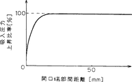
図25は本発明の実施例10における吸入圧力の上昇比率変化を示す特性図である。
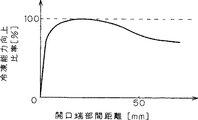
図26は本発明の実施例10における冷凍能力向上比率変化を示す特性図である。
図27は本発明の実施例10における騒音変化を示す特性図である。
図28は本発明の実施例11による密閉型圧縮機の縦断面図である。
図29は本発明の実施例11による密閉型圧縮機の図28のD−D線における断面図である。
図30は本発明の実施例11における吸入パイプの開口端部を示す縦断面図である。
図31は本発明の実施例11における吸入パイプの開口端部の開口面を示す図である。
図32は本発明の実施例12による密閉型圧縮機の縦断面図である。
図33は本発明の実施例12による密閉型圧縮機の図32のE−E線における断面図である。
図34本発明の実施例12における起動時のシリンダーヘッド部分の要部を示す平面断面図である。
図35は本発明の実施例12における安定運転時のシリンダーヘッド部分の要部を示す平面断面図である。
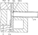
図36は本発明の実施例13による密閉型圧縮機のピストンの往復方向に直交する方向に共鳴モードの節部を持つ時の平面断面図である。
図37は本発明の実施例13による密閉型圧縮機のピストンの往復方向に直交する方向に共鳴モードの節部を持つ時の正面図である。
図38は本発明の実施例14による密閉型圧縮機のピストンの往復方向に直交する方向に共鳴モードの節部を持つ時の縦断面図である。
図39は本発明の実施例14による密閉型圧縮機のピストンの往復方向に直交する方向に共鳴モードの節部を持つ時の平面断面図である。
図40は本発明の実施例15による密閉型圧縮機の縦断面図である。
図41は本発明の実施例15による図40に示した密閉型圧縮機のB−B線における正面断面図である。
図42は本発明の実施例15による別の吸入流路形状を有する密閉型圧縮機の縦断面図である。
図43は本発明の実施例15による図42に示した密閉型圧縮機のC−C線における正面断面図である。
図44は本発明の実施例16による密閉型圧縮機の縦断面図である。
図45は本発明の実施例16による図44に示した密閉型圧縮機のD−D線における正面断面図である。
図46は本発明の実施例17による密閉型圧縮機の縦断面図である。
図47は本発明の実施例17による図46に示した密閉型圧縮機のE−E線における正面断面図である。
図48は本発明の実施例18による密閉型圧縮機を示す平面断面図である。
図49は図48のB−B線における正面断面図である。
図50は本発明の実施例18による密閉型圧縮機の高負荷運転時における吸入流路の要部断面図である。
図51は本発明の実施例18による密閉型圧縮機の通常運転時における吸入流路の要部断面図である。
図52は本発明の実施例19による密閉型圧縮機を示す平面断面図である。
図53は図52のC−C線における正面断面図である。
図54は本発明の実施例19による密閉型圧縮機の高負荷運転時における吸入流路の要部断面図である。
図55は本発明の実施例19による密閉型圧縮機の通常運転時における吸入流路の要部断面図である。
図56は本発明の実施例20による密閉型圧縮機を示す平面断面図である。
図57は本発明の実施例20による密閉型圧縮機を含む冷凍装置の制御ブロック図である。
図58は実施例20の密閉型圧縮機における回転数制御時の冷凍能力変化を示す特性図である。
図59は本発明の実施例21による密閉型圧縮機を示す平面断面図である。
図60は実施例21の密閉型圧縮機の図59のB−B線における正面断面図である。
図61は実施例21の密閉型圧縮機の吸入流路付近を示す断面図である。
図62は本発明の実施例22による密閉型圧縮機のシリンダー付近を示す断面図である。
図63は本発明の実施例23による密閉型圧縮機の低外気温時の停止時におけるシリンダー付近を示す断面図である。
図64は実施例23の密閉型圧縮機の高外気温時の停止時におけるシリンダー付近を示す断面図である。
図65は本発明の実施例24による密閉型圧縮機の低外気温時の停止時におけるシリンダー付近を示す断面図である。
図66は実施例24の密閉型圧縮機の高外気温時の停止時におけるシリンダー付近を示す断面図である。
図67は従来の低騒音化を目的とした密閉型圧縮機の縦断面図である。
図68は従来の低騒音化を目的とした密閉型圧縮機の平面断面図である。
図69は従来の冷凍能力向上を目的とした密閉型圧縮機の縦断面図である。
図70は図69の密閉型圧縮機のA−A線における平面断面図である。
図71は図69の密閉型圧縮機における要部断面図である。
図72は冷媒ガス挙動の説明図である。
発明を実施するための最良の形態
以下、本発明の各実施例について、添付の図を用いて説明する。
《実施例1》
まず、本発明の密閉型圧縮機の一例である実施例1について説明する。
図1は本発明の実施例1による密閉型圧縮機を示す平面断面図であり、ピストンの往復方向(図1矢印w−w)を含む水平面における当該往復方向と直角の方向に共振モードの節部をもつ密閉型圧縮機を示す。図2は本発明の実施例1における密閉型圧縮機のピストンの往復方向を含む水平面における当該往復方向と直角の方向に共振モードを有する場合の状態を示す正面図である。図3は本発明の実施例1における密閉型圧縮機のクランクシャフトの軸方向に共振モードを有する場合の状態を示す正面図である。
図1及び図2において、密閉型圧縮機1は、下シェル3と上シェル4から構成された密閉容器2を有している。密閉容器2内の電動圧縮要素5は、上方部に機械部6、下方部にモーター部7が配置されるようにコイルばね8により密閉容器2に弾性支持されている。機械部6は、ブロック9と一体に設けられたシリンダー10、図1の矢印w上を図1において左右方向に往復運動するピストン11、クランクシャフト12、コンロッド13(連接棒)等により構成されている。モーター部7は、クランクシャフト12に焼ばめ固定(加熱後にはめ込み固着すること)されたローター、ステーター等により構成されている。ステーターはブロック9にねじ止め固定されている。潤滑油17は密閉容器2の下部に貯溜されている。
冷媒ガスをシリンダー10内に吸入する吸入パイプ22は、その一端が機械部6に吸入室25を介して取り付けられ、他端が開口端部22aとして密閉容器2内に配置されている。このため、吸入パイプ22はシリンダー10内と密閉容器2内とを連通させている。この吸入パイプ22は形状記憶合金により形成されており、吸入パイプ22の開口端部22aは温度変化に応じて所望の位置となるように構成されている。吸入パイプ22の開口端部22aは移動可能であって、後に述べる条件に従って、下記3つの平面の少なくとも1つ以上の平面上の何れかに配置される。
(1)前記密閉容器2の水平断面(図1の紙面に平行な断面)にてその断面積が実質的に最大となる面(図2の直線Hにて示す水平面)の重心(水平断面部分における重心の位置)を通る第1の線分(図1の矢印vにて示す線分)であり、かつ当該第1の線分(v)が(図2の直線Hにて示す水平面において)前記密閉容器2の内壁面間の距離が最小となる位置にあり、前記第1の線分(v)の中心点において前記第1の線分(v)と実質的に直交する第1の平面(図1の直線Wにて示す平面)上(図1において開口端部22aを示した位置)、又は
(2)前記第1の線分(v)を含む水平面(H)において、前記第1の線分(v)と実質的に直交する前記密閉容器2の内壁面間の第2の線分(図1の矢印wにて示す線分)の中心点を通り、かつ前記第2の線分(w)と実質的に直交する第2の平面(図1の直線V及び図2の直線Xにて示す鉛直平面)上(図2において開口端部22aを示している位置)、又は
(3)前記密閉容器2の鉛直方向における内壁上面と前記潤滑油面との間の最大距離となる第3の線分(図3の矢印xにて示す線分)の中心点を通り、かつ前記第3の線分(x)と実質的に直交する第3の平面(図3の直線Yにて示す水平面)上(図3において開口端部22aを示した位置)、
の3つの平面の少なくとも1つの平面上に吸入パイプ22の開口端部22aが配置されている。
次に、上記のように構成された実施例1の密閉型圧縮機について、その動作について説明する。
冷凍冷蔵装置等のシステムから循環してきた冷媒ガスは、一旦密閉容器2内空間に開放され、そしてブロック9に固定された吸入パイプ22を介してシリンダー10内に吸入される。シリンダー10内の冷媒ガスはピストン11により圧縮される。その際、冷媒ガスはクランクシャフト12の1/2回転でシリンダー10内に吸入され、後の1/2回転で圧縮される。
そのため、冷媒ガスは連続的にシリンダー10内に吸入されないため、吸入パイプ22に冷媒ガスの圧力脈動が生じる。従って、その圧力脈動が密閉容器2内の空間を加振し、ピストン11の往復方向、ピストン11の往復方向を含む水平面における当該往復方向と直角の方向、及びクランクシャフト12の軸方向において共鳴モードが生じる。
その際、ピストン11の往復方向、ピストン11の往復方向を含む水平面における当該往復方向と直角の方向、及びクランクシャフト12の軸方向における共鳴モードの圧力脈動のエネルギーは冷媒ガス中の音速(冷媒ガスを通る音の速度)により変化する。
例えば、高外気温等で冷媒ガスの温度が高く、冷媒ガス中の音速が早くなった場合、共鳴モードの節部はピストン11の往復方向を含む水平面における当該往復方向と直角の方向に生じる。
その際、吸入パイプ22の密閉容器2内空間の開口端部22aをピストン11の往復方向を含む水平面における当該往復方向と直角の方向の共鳴モードの節部と一致するように設けることにより、圧力脈動は加振されず、共鳴音の発生を抑えることができる。図2は実施例1における密閉型圧縮機のピストン11の往復方向を含む水平面における当該往復方向と直角の方向の共振モードの節部と開口端部22aとが一致した状態を示す正面図である。
次に、低外気温等で冷媒ガスの温度が下がり、冷媒ガス中の音速が遅くなった場合、共鳴モードの節部はクランクシャフト12の軸方向に生じる。
この時、冷媒ガスの温度が低下して、吸入パイプ22の温度が低下するのに伴い、形状記憶合金で形成された吸入パイプ22の密閉容器2内空間の開口端部22aは鉛直下方向に曲がる。
このため、吸入パイプ22の密閉容器2内空間の開口端部22aは、クランクシャフト12の軸方向の共鳴モードの節部と一致する位置に配置されるため、圧力脈動は加振されず、共鳴音の発生を抑えることができる。図3は実施例1における密閉型圧縮機のクランクシャフト12の軸方向の共振モードの節部と開口端部22aとが一致した状態を示す正面断面図である。
実施例1の密閉型圧縮機においては、外気温の温度変化により冷媒ガス中の音速が変化し、共鳴周波数の共鳴モードの節部が変化しても、常に吸入パイプ22の閉口端部22aが共鳴モードの節部の位置となるように構成されている。このため、実施例1の密閉型圧縮機は、共鳴音の発生を抑え、低騒音化を達成することができる。
以上のように、実施例1の密閉型圧縮機において、シリンダー10内と密閉容器2内とを連通させている吸入パイプ22は、形状記憶合金により形成されており、吸入パイプ22の開口端部22aは、
(1)前記密閉容器2の水平断面にてその断面積が実質的に最大となる面(H)の重心を通る第1の線分(v)であり、かつ当該第1の線分(v)が前記密閉容器2の内壁面間の距離が最小となる位置にあり、前記第1の線分(v)の中心点において前記第1の線分(v)と実質的に直交する第1の平面(W)、
(2)前記第1の線分(v)を含む水平面(H)において、前記第1の線分(v)と実質的に直交する前記密閉容器2の内壁面間の第2の線分(w)の中心点を通り、かつ前記第2の線分(w)と実質的に直交する第2の平面(V)、又は
(3)前記密閉容器2の鉛直方向における内壁上面と前記潤滑油面との間の最大距離となる第3の線分(x)の中心点を通り、かつ前記第3の線分(x)と実質的に直交する第3の平面(Y)、の3つの平面のうち少なくとも1つの平面上に配置されている。
実施例1の密閉型圧縮機は、冷媒ガスの温度変化により冷媒ガス中の音速が変化し、共鳴周波数の共鳴モードの節部が変化しても、常に吸入パイプ22の開口端部22aが共鳴モードの節部となるよう配置されている。それ故、吸入パイプ22内における共鳴音の発生を防ぎ、騒音の発生を防止することができる。
なお、実施例1においては、外気温で冷媒ガスの温度が変化し、冷媒ガス中の音速が変化する場合であった。しかし、冷媒ガス中の音速が変化する条件の下ならば、圧力等の変化に起因する場合でも、上記実施例と同様の効果を有する。
上記実施例1において、高外気温時の共鳴モードの節部がピストン11の往復方向を含む水平面における当該往復方向と直角の方向にある場合と低外気温時の共鳴モードの節部がクランクシャフト12の軸方向にある場合について説明した。しかし、ピストン11の往復方向、ピストン11の往復方向を含む水平面における当該往復方向と直角の方向、クランクシャフト12の軸方向、および各々の方向の付近など共鳴モードの節部の変化に追従して吸入パイプ22の開口端部22aの位置が移動するように構成することにより、優れた低騒音化を達成した密閉型圧縮機を得ることができる。
なお、共鳴モードの節部の変化に伴い、吸入パイプ22の開口端部22aが追従して移動するように電気的又は機械的に構成されたものでも、上記実施例1と同様の効果が得られる。
《実施例2》
次に、本発明の密閉型圧縮機の一例である実施例2について添付の図を用いて説明する。
図4は本発明の実施例2による密閉型圧縮機の縦断面図を示す。図5は本発明の実施例2による密閉型圧縮機の平面断面図を示す。なお、実施例2の密閉型圧縮機において、前述の実施例1の密閉型圧縮機と同じ機能、構成を有するものには同じ符号を付して、その説明は省略する。
図4及び図5において、機械部6のシリンダー10の端面に固着されたバルブプレート19には吸入孔19aが形成されており、この吸入孔19aには吸入パイプ23の一端が直接接続されている。吸入パイプ23の他端は、開口端部23aとして密閉容器2内空間に配置されている。
吸入パイプ23の開口端部23aは、下記3つの平面の少なくとも1つ以上の平面上に配置される。
(1)前記密閉容器2の水平断面(図5の紙面に平行な断面)にてその断面積が実質的に最大となる面(図4の直線Hにて示す水平面)の重心(水平断面部分における重心の位置)を通る第1の線分(図5の矢印vにて示す線分)であり、かつ当該第1の線分(v)が(図4の直線Hにて示す水平面において)前記密閉容器2の内壁面間の距離が最小となる位置にあり、前記第1の線分(v)の中心点において前記第1の線分(v)と実質的に直交する第1の平面(図5の直線Wにて示す平面)上(図5において開口端部22aを示した位置)、
(2)前記第1の線分(v)を含む水平面(H)において、前記第1の線分(v)と実質的に直交する前記密閉容器2の内壁面間の第2の線分(図5の矢印wにて示す線分)の中心点を通り、かつ前記第2の線分(w)と実質的に直交する第2の平面(図5の直線Vにて示す鉛直平面)上、又は
(3)前記密閉容器2の鉛直方向における内壁上面と前記潤滑油面との間の最大距離となる第3の線分(図4の矢印xにて示す線分)の中心点を通り、かつ前記第3の線分(x)と実質的に直交する第3の平面(図4の直線Yにて示す水平面)上、
の3つの平面の少なくとも1つの平面上に吸入パイプ22の開口端部22aが配置されている。
図4及び図5に示す密閉型圧縮機は、吸入パイプ23の開口端部23aが第1の平面(W)上に配置されている場合である。
次に、上記のように構成された実施例2の密閉型圧縮機について、その動作を説明する。
シリンダー10内で発生した圧力波は、バルブプレート19の吸入孔19aを通り、冷媒ガスの流れと逆方向に伝播して、密閉容器2内の空間で位相が反転した反射波となる。この反射波は、冷媒ガスの流れと順方向に伝播し、吸入孔19aに戻ってくる。
この反射波が吸入孔19aに到達する時点と、シリンダー10内の容積が最大になる時点(吸入完了時点)とを一致させることにより、吸入完了時点で反射波の持つ圧力エネルギーが冷媒ガスに付加され、冷媒ガスの吸入圧力が上昇する。
この結果、シリンダー10内には、より密度の高い冷媒ガスが充填されることになり、圧縮1行程当たりの吐出冷媒量が増加し、冷媒循環量が増加して、冷凍能力が大幅に向上する。このように、実施例2の密閉型圧縮機においては、冷媒ガスの吸入損失が低減し、冷却効率を向上させることができる。
その際、シリンダー10内で発生した圧力波は衝撃音を発生させると共に、密閉容器2内の空間を加振し、ピストン11の往復方向、ピストン11の往復方向を含む水平面における当該往復方向と直角の方向、及びクランクシャフト12の軸方向に共鳴モードを発生させる。
図4及び図5に示す実施例2の密閉型圧縮機においては、ピストン11の往復方向を含む水平面における当該往復方向と直角の方向の共鳴モードの節部に、吸入パイプ23の密閉容器2内空間の開口端部23aを配置している。このため、実施例2の密閉型圧縮機は、吸入パイプ23の開口端部23aが共鳴モードの節部の位置となり、吸入パイプ23の圧力波により発生する衝撃音の発生を大幅に抑制して、低騒音化を達成することができる。
以上のように、実施例2の密閉型圧縮機は、吸入パイプ23の一端がバルブプレート19の吸入孔19aに直結され、他端が開口端部23aとして密閉容器2の空間内の所定の平面内に配置されている。このため、吸入パイプ23の開口端部23aが共鳴モードの節部となることにより、密閉型圧縮機は吸入パイプ23の圧力波により発生する衝撃音の発生を大幅に抑制して、騒音を低減することができる。このため、実施例2の密閉型圧縮機は、冷凍能力を向上させ、吸入損失を低減することができる高効率の密閉型圧縮機となる。
なお、実施例2において、吸入パイプ23の密閉容器2内空間の開口端部23aを、ピストン11の往復方向と直角方向の共鳴モードの節部とした構成のもので説明した。しかし、ピストン11の往復方向の共鳴モードの節部、またはクランクシャフト12の軸方向の共鳴モードの節部など、吸入パイプ23の密閉容器2内空間の開口端部が各方向の共鳴モードの節部であれば、上記実施例2と同様の効果を奏する。
《実施例3》
次に、本発明の密閉型圧縮機の一例である実施例3について添付の図を用いて説明する。
図6は本発明の実施例3による密閉型圧縮機の縦断面図を示す。図7は本発明の実施例3による密閉型圧縮機の冷媒ガス中の音速が早いときの要部縦断面図を示す。図8は本発明の実施例3による密閉型圧縮機の冷媒ガス中の音速が遅いときの要部縦断面図を示す。なお、実施例3の密閉型圧縮機において、前述の実施例1又は実施例2の密閉型圧縮機と同じ機能、構成を有するものには同じ符号を付して、その説明は省略する。
図6、図7及び図8において、機械部6のシリンダー10の端面に固着されたバルブプレート19には吸入孔19aが形成されている。この吸入孔19aには吸入パイプ24の一端が直接接続されている。吸入パイプ24の他端は、開口端部24aとして密閉容器2内空間に配置されている。
吸入パイプ24は長さ可変機構を備えている。図7及び図8において、符号24bは吸入パイプ24に形成された開口穴である。この開口穴24bは吸入パイプ24内空間と密閉容器2内空間とを連通させる開口端部24a以外の1つ以上の連通孔である。符号26は開口穴24bを開閉するバイメタルあるいは形状記憶合金等で形成された開口穴蓋である。
次に、上記のように構成された実施例3の密閉型圧縮機について、その動作を説明する。
シリンダー10内で発生した圧力波は、バルブプレート19の吸入穴19aを通って冷媒ガスの流れと逆方向に伝播し、密閉容器2内の空間で位相の反転した反射波となる。位相の反転した反射波は、冷媒ガスの流れと順方向に伝播し、吸入孔19aに戻ってくる。
この反射波が吸入孔19aに到達する時点と、シリンダー10内の容積が最大になる時点(吸入完了時点)とを一致させることにより、吸入完了時点で反射波の持つ圧力エネルギーが付加され、冷媒ガス吸入圧力は上昇する。
そのため、シリンダー10内には、より密度の高い冷媒ガスが充填されることになり、圧縮1行程当たりの吐出冷媒量が増加し、冷媒循環量が増加して、冷凍能力が大幅に向上する。
しかしながら、圧力波や反射波の波長は音速により変化するため、吸入完了時点で反射波の持つ圧力エネルギーの付加のタイミングに誤差が生じて、冷媒ガスの吸入圧力の上昇率が低下する。
そこで、図7に示すように、高外気温時などで冷媒ガス中の音速が早いときは、バイメタルあるいは形状記憶合金等で形成された開口穴蓋26が開口穴25を閉じることにより、吸入パイプ24の開口端が吸入パイプ24の先端である開口端部24aとなり、吸入パイプ24の長さが長くなる。
この結果、冷媒ガス中の音速が早くなり波長が変化した分、吸入パイプ24を長くすることができ、反射波が吸入孔19aに到達する時点と、シリンダー10内の容積が最大になる時点(吸入完了時点)とを一致させることができる。このため、実施例3の密閉型圧縮機は吸入完了時点で反射波の持つ圧力エネルギーが冷媒ガスに付加され、冷媒ガスの吸入圧力を上昇させることができる。
図8に示すように、低外気温時などで冷媒ガス中の音速が遅いときは、バイメタルあるいは形状記憶合金等で形成された開口穴蓋26が開口穴25を開放して、吸入パイプ24の開口端が吸入パイプ24の開口端部24aより手前となり、吸入パイプ24の長さが短くなることに相当する。
この結果、冷媒ガス中の音速が遅くなった場合、吸入パイプ24を短くすることで、反射波が吸入孔19aに到達する時点と、シリンダー10内の容積が最大になる時点(吸入完了時点)とを一致させることができ、吸入完了時点で反射波の持つ圧力エネルギーが冷媒ガスに付加され、冷媒ガスの吸入圧力を上昇させることができる。
以上のように、吸入パイプ24の長さを変化させることにより、外気温が変化し冷媒ガスの温度変化により冷媒ガス中の音速が変化しても、反射波が吸入孔19aに到達する時点と、シリンダー10内の容積が最大になる時点(吸入完了時点)とを一致させることができる。このため、実施例3の密閉型圧縮機は、吸入完了時点で反射波の持つ圧力エネルギーが冷媒ガスに付加され、吸入圧力を上昇させることができる。
これにより、実施例3の密閉型圧縮機は、常に吸入圧力が上昇し、圧縮1行程当たりの吐出冷媒量が増加し、冷媒循環量が増加する。このため、実施例3の密閉型圧縮機は、冷凍能力を向上させ、かつ吸入損失を低減させて、高い冷却効率を有する。
以上のように、実施例3の密閉型圧縮機は、吸入パイプ24の一端が密閉容器2内の空間に開口端部24aとして配置され、他端がバルブプレート19の吸入孔19aに直結されている。また、吸入パイプ24には長さ可変機構が設けられている。この長さ可変機構は、吸入パイプ24に吸入パイプ24内と密閉容器内2の空間を連通させる開口端以外の1つ以上の開口穴25と、この開口穴25を開閉するバイメタルあるいは形状記憶合金等で形成された開口穴蓋26で構成されている。この長さ可変機構により吸入パイプ24の長さを変化させることにより、外気温が変化して冷媒ガスの温度変化により冷媒ガス中の音速が変化しても、反射波が吸入孔19aに到達する時点と、シリンダー10内の容積が最大になる時点(吸入完了時点)とを一致させることができる。このため、吸入完了時点で反射波の持つ圧力エネルギーが冷媒ガスに付加され、冷媒ガスの吸入圧力を上昇させることができる。
これにより、実施例3の密閉型圧縮機においては、常に吸入圧力が上昇し、圧縮1行程当たりの吐出冷媒量が増加して、冷媒循環量が増加する。このため、実施例3の密閉型圧縮機は、冷凍能力が向上し、かつ吸入損失を低減させて高い冷却効率を有する密閉型圧縮機となる。
なお、実施例3において、外気温で冷媒ガスの温度が変化し、冷媒ガス中の音速が変化するとした。しかし、冷媒ガス中の音速が変化する条件ならば圧力等が変化した場合にも実施例3の密閉型圧縮機は有用である。
実施例3において、長さ可変機構は吸入パイプ24と、吸入パイプ24に吸入パイプ24内と密閉容器2内の空間を連通させる開口端部24a以外の1つ以上の開口穴25と、開口穴25の部分に開閉自在に設けられたバイメタルあるいは形状記憶合金等でできた開口穴蓋26で構成されている。しかし、長さ可変機構は、冷媒ガス中の音速の変化に伴いパイプ長さが変化する調整機構であれば、上記実施例3と同様の効果が得られることは言うまでもない。
《実施例4》
次に、本発明の密閉型圧縮機の一例である実施例4について添付の図を用いて説明する。
図9は本発明の実施例4による密閉型圧縮機の断面図を示す。図10は本発明の実施例4による密閉型圧縮機の高外気温時における図9のB−B断面図を示す。図11は本発明の実施例4による密閉型圧縮機の低外気温時における図9のB−B断面図を示す。なお、実施例4の密閉型圧縮機において、前述の実施例1、実施例2又は実施例3の密閉型圧縮機と同じ機能、構成を有するものには同じ符号を付して、その説明は省略する。
図9において、機械部6のシリンダー10の端面に固着されたバルブプレート19には吸入孔19aが形成されており、この吸入孔19aには吸入パイプ27の一端が直接接続されている。吸入パイプ27の他端は、開口端部27aとして密閉容器2内空間に配置されている。吸入パイプ27は線膨脹係数の大きい材料により形成されている。
次に、上記のように構成された実施例4の密閉型圧縮機について、その動作を説明する。
シリンダー10内で発生した圧力波は、バルブプレート19の吸入孔19aを通り冷媒ガスの流れと逆方向に伝播し、密閉容器2内の空間で位相の反転した反射波となる。この反射波は冷媒ガスの流れと順方向に伝播して、吸入孔19aに戻ってくる。
この反射波が吸入孔19aに到達する時点と、シリンダー10内の容積が最大になる時点(吸入完了時点)とを一致させることにより、吸入完了時点で反射波の持つ圧力エネルギーが冷媒ガスに付加され、冷媒ガスの吸入圧力が上昇する。
そのため、シリンダー10内には、より密度の高い冷媒ガスが充填されることにより、圧縮1行程当たりの吐出冷媒量が増加し、冷媒循環量が増加して、冷凍能力が大幅に向上する。
その際、シリンダー10内で発生した圧力波は衝撃音を発生させる。しかしながら、圧力波や反射波の波長は音速により変化するため、吸入完了時点で反射波の持つ圧力エネルギーの冷媒ガスへの付加のタイミングに誤差が生じ、冷媒ガスの吸入圧力はその上昇率が低下する。
そこで、図10に示すように、高外気温時などで冷媒ガス中の音速が早いときは、線膨脹係数の大きい材料からなる吸入パイプ27は、高温により膨脹して、吸入パイプ27の内径断面積が大きくなる。
このように、冷媒ガス中の音速が早くなり、反射波の波長の変化に応じて、吸入パイプ27の内径断面積が大きくなる。これにより、冷媒ガスの流速を下げ、反射波の戻りタイミングを遅くすることで、反射波が吸入孔19aに到達する時点と、シリンダー10内の容積が最大になる時点(吸入完了時点)とを一致させることができる。このため、実施例4の密閉型圧縮機では、吸入完了時点で反射波の持つ圧力エネルギーが冷媒ガスへ付加され、冷媒ガスの吸入圧力を上昇させることができる。
図11に示すように、低外気温時などで冷媒ガス中の音速が遅いときは、線膨脹係数の大きい材料からなる吸入パイプ27は、温度低下のために収縮して、吸入パイプ27の内径断面積が小さくなる。
このように、冷媒ガス中の音速が遅くなった場合、吸入パイプ27の内径断面積を小さくすることにより、冷媒ガスの流速を上げ、反射波の戻りタイミングを早くすることで、反射波が吸入孔19aに到達する時点と、シリンダー10内の容積が最大になる時点(吸入完了時点)とを一致させることができる。このため、吸入完了時点で反射波の持つ圧力エネルギーが冷媒ガスへ付加され、冷媒ガスの吸入圧力を上昇させることができる。ただし、吸入パイプ27の内径断面積が小さくなることにより、反射波の持つ圧力エネルギーが少し減少し、吸入圧力を上昇効果は少し低下する。
しかし、高外気温時に比べ大きな冷凍能力の向上を必要としないところの低外気温時は、吸入パイプ27の内径断面積が小さくなる。このように、冷凍能力の効果が少し減少するものの、外気温が低い冬などにおいては部屋を閉めきることが多く、夏以上に騒音が気になるような低外気温時において、実施例4の密閉型圧縮機は、吸入パイプ27の内径断面積を絞り、衝撃音を大幅に抑制して、騒音を大幅に減少させることができる。
従って、吸入パイプ27の内径断面積を変化させることにより、外気温が変化し冷媒ガス中の音速が変化しても、常に反射波が吸入孔19aに到達する時点と、シリンダー10内の容積が最大になる時点(吸入完了時点)とを一致させることができる。このため、実施例4の密閉型圧縮機は、吸入完了時点で反射波の持つ圧力エネルギーが冷媒ガスへ付加でき、冷媒ガスの吸入圧力が上昇して、圧縮1行程当たりの吐出冷媒量が増加し、冷媒循環量が増加し、冷凍能力が向上する。
高外気温時に比べ大きな冷凍能力の向上を必要としない低外気温時には、吸入パイプ27の内径断面積が小さくなり、冷凍能力の向上が少し減少する。しかし、外気温度が低くなるほど吸入パイプ27の内径断面積が絞られる。このため、実施例4の密閉型圧縮機は騒音の発生を大幅に抑制することができる。
以上のように、実施例4の密閉型圧縮機は、吸入パイプ27の一端が密閉容器2内の空間に開口し、他端がバルブプレート19の吸入孔19aに直結され、かつ線膨脹係数の大きい材料により構成されている。このため、外気温が変化し冷媒ガス中の音速が変化しても、外気温度の変化に応じて吸入パイプ27の内径断面積を変化させることにより、反射波が吸入孔19aに到達する時点と、シリンダー10内の容積が最大になる時点(吸入完了時点)とを常に一致させることができる。このため、実施例4の密閉型圧縮機においては、吸入完了時点で反射波の持つ圧力エネルギーが冷媒ガスへ付加でき、冷媒ガスの吸入圧力が上昇する。このため、実施例4の密閉型圧縮機は、圧縮1行程当たりの吐出冷媒量が増加し、冷媒循環量が増加し、冷凍能力が向上する。
高外気温時に比べ大きな冷凍能力の向上を必要としない低外気温時は、吸入パイプ27の内径断面積が小さくなる。それ故、実施例4の密閉型圧縮機は、冷凍能力の向上が少し減少するものの、外気温度が低くなるほど吸入パイプ27の内径断面積が絞られる。このため、実施例4の密閉型圧縮機は、騒音を大幅に低減することができる。
なお、実施例4において、外気温で冷媒ガスの温度が変化し、冷媒ガス中の音速が変化するとした。しかし、冷媒ガス中の音速が変化する条件ならば圧力等が変化する場合でも実施例4の密閉型圧縮機は有用である。
実施例4において、吸入パイプ27の内径断面積可変機構は線膨脹係数の大きい材料を用いて吸入パイプ27を構成した。しかし、冷媒ガス中の音速の変化に伴い吸入パイプ27の内径断面積が変化する調整機構を用いるのであれば、上記実施例4と同様の効果が得られることは言うまでもない。
《実施例5》
次に、本発明の密閉型圧縮機の一例である実施例5について添付の図を用いて説明する。
図12は本発明の実施例5の密閉型圧縮機における冷媒ガスの挙動を示す説明図である。図13は実施例5の密閉型圧縮機の縦断面図を示す。図14は実施例5の密閉型圧縮機における冷媒ガス挙動とクランクシャフトとの関係を示す説明図である。なお、実施例5の密閉型圧縮機において、前述の各実施例の密閉型圧縮機と同じ機能、構成を有するものには同じ符号を付して、その説明は省略する。
図12及び図13において、機械部6のシリンダー10の端面に固着されたバルブプレート19には吸入孔19aが形成されており、この吸入孔19aには吸入パイプ229の一端が直接接続されている。吸入パイプ229の他端は、開口端部229aとして密閉容器2内空間に配置されている。
図14において、冷媒ガスは、吸入行程の開始(図14の(a)の時点)では、クランクシャフト12が基準位置にあり、バルブプレート19の吸入孔19aは塞がれている。このため、冷媒ガスの流れは停止している。
次に、クランクシャフト12が回転して、ピストン11が右側に移動し、シリンダー10内の容積が急激に増加する。この結果、シリンダー10内の空間と密閉容器2内の空間とに圧力差が発生し、サクションリード20が開き始める(図14の(b)の時点)。このときのクランクシャフト12の回転位置(以後、クランク角度と称す)をθs(rad)とする。
サクションリード20が開き、冷媒ガスは吸入パイプ229内を右方向(シリンダー10の方向)へと流れ始める。このとき同時に、シリンダー10内の容積が急激に増加することに起因して、シリンダー10内において圧力波Waが発生する。シリンダー10内の圧力波Waは、開口である吸入孔19aを経て、冷媒ガスの流れと逆方向に吸入パイプ229内を密閉容器2内の空間に向かって伝播していく。
密閉容器2内の空間まで到達した圧力波Waは、冷媒ガスのよどみ状態の密閉容器2内の空間において反転した反射波Wbとなる。この反射波Wbは、吸入パイプ229内を冷媒ガスの流れと同一方向に伝播していく(図14の(c)の時点)。
そして、反射波Wbは、冷媒ガスの流れと順方向に伝播して、バルブプレート19の吸入孔19aに戻ってくる(図14の(d)の時点)。
図14の(a)に示す上死点のクランク角度を0(rad)としたとき、サクションリード20の開き始め(図14の(b))のクランク角度をθs(rad)とし、吸入パイプ229の長さをL(m)とし、クランクシャフト12の回転数をf(Hz)とし、吸入パイプ229内の吸入される冷媒ガス中の音速をAs(m/sec)とし、吸入開始時に吸入孔19aにおいて発生する圧力波が反射波となって吸入孔19aに戻るクランク角度をθr(rad)とすると、これらの関係は下記(式1)により表される。
θr=θs+4π×L×f/As ・・・・(式1)
1.4(rad)≦θr≦3.0(rad)・・・・(式2)
このとき、圧力波の戻りクランク角度θrは(式2)の範囲に入るように吸入パイプ229の長さL等が調整されている。
次に、上記のように構成された実施例5の密閉型圧縮機について、その動作を説明する。
吸入行程時にサクションリード20が開くと同時に発生した圧力波Waは、冷媒ガスの流れと逆方向に伝播する。それはさらに、密閉容器2内の空間で位相の反転した反射波Wbとなり、冷媒ガスの流れと順方向に伝播し、吸入孔19aに戻ってくる。また、反射波Wbには幅があるので(式1)で示すクランク角度θrで反射波の波頭が吸入孔19aに戻る。また、それに遅れてクランク角度がさらに進んだ時に反射波Wbの波尾が吸入孔19aに戻り、幅を持った反射波Wbの戻りが完了する。
次に、反射波Wbが吸入孔19aに戻るときのクランク角度と冷凍能力の向上効果との関係を吸入パイプ229の長さを例にとって説明する。
吸入パイプ229の長さLが短いときは、(式1)からわかるように反射波Wbの戻りクランク角度θrは小さくなる、すなわち反射波Wbは吸入行程の早いタイミングで返ってくる。そのため、吸入行程が完了する前に幅を持った反射波Wbが全て吸入孔19aに戻り終ることが起こり得る。その場合には、反射波Wbの戻りが完了した後は吸入孔19aにおける圧力が下がることになり、吸入行程の途中であるにもかかわらず、サクションリード20が閉じたり、シリンダー10内から吸入パイプ229に冷媒ガスが逆流したりする。このため、シリンダー10内に吸入する冷媒ガスの密度を十分に高めることができず、冷凍能力の向上効果は小さくなってしまう。
また、逆に吸入パイプ229の長さLが長いときは、反射波Wbは吸入行程の遅いタイミングで返ってくる。あるいは吸入行程が終わった後で返ってくることになる。そのため、幅を持った反射波Wbが全て吸入孔19aに戻り終わる前に吸入行程が終わり、シリンダー10内に吸入する冷媒ガスの密度を十分に高めることができない。従って、冷凍能力の向上効果は小さくなってしまう。
このように、吸入パイプ229の長さは、短過ぎても長過ぎても冷凍能力の向上効果は小さくなる。冷凍能力の向上効果が最大限になる最適な吸入パイプ229の長さ、すなわち最適な反射波Wbの戻りクランク角度θrは存在する。しかし、反射波Wbには幅があるため、冷凍能力の向上効果がほぼ最大限に得られる反射波の戻りクランク角度も幅を有する。往復式の密閉型圧縮機の場合、反射波の戻りクランク角度θrは、(式2)の範囲において冷凍能力の向上効果がほぼ最大限に得られる。
例えば、冷媒がHFC−134aで、吸入される冷媒ガスの圧力が0.085(MPa)、その冷媒ガスの温度が80(℃)の場合、音速Asは176.3(m/s)となる。そして、クラクンシャフト12の回転数fを58.5(Hz)、サクションリード20の開き始めのクランク角度θsを0.96(rad)とすると、(式2)を満たすためには吸入パイプ229の長さLを0.10〜0.48(m)とすればよい。
このように、本発明の実施例5の密閉型圧縮機は反射波の戻りクランク角度が最適となるよう吸入パイプ229の長さ等が調整されているので、冷凍能力の向上効果が最大限に得られる。
以上のように、本実施例5の密閉型圧縮機では、サクションリード20の開き始めのクランク角度をθs(rad)とし、吸入パイプ229の長さをL(m)とし、クランクシャフト12の回転数をf(Hz)とし、吸入パイプ229内の吸入される冷媒ガス中の音速をAs(m/sec)として、吸入開始時に吸入孔19aにおいて発生する(式1)で示される圧力波の戻りクランク角度θr(rad)が(式2)の範囲になるように構成されている。
このため、本実施例5の密閉型圧縮機は、反射波Wbが吸入孔19aに戻ってくるクランク角度が最適となり、吸入圧力を上昇させ最大限の冷凍能力の向上効果を得ることができる。
なお、冷媒種類や吸入される冷媒ガスの圧力、温度が違い音速が違う場合、反射波Wbの戻りクランク角度が(式2)を満たされるように吸入パイプ229の長さを調整すれば、上記実施例5と同様の効果が得られる。また、クランクシャフト12の回転周波数、サクションリード20の開き始めのクランク角度が違う場合でも、反射波Wbの戻りクランク角度が(式2)を満たされるように吸入パイプ229の長さを調整すれば、上記実施例5と同様の効果が得られる。
《実施例6》
次に、本発明の密閉型圧縮機の一例である実施例6について添付の図を用いて説明する。
図15は本発明の実施例6による密閉型圧縮機の縦断面図を示す。図16Aは本発明の実施例6による低外気温時の吸入パイプの開口部付近の断面図を示す。図16Bは本発明の実施例6による高外気温時の吸入パイプの開口部付近の断面図を示す。なお、実施例6の密閉型圧縮機において、前述の各実施例の密閉型圧縮機と同じ機能、構成を有するものには同じ符号を付して、その説明は省略する。
図15、図16A及び図16Bにおいて、機械部6のシリンダー10の端面に固着されたバルブプレート19には吸入孔19aが形成されており、この吸入孔19aには吸入パイプ239の一端が直接接続されている。吸入パイプ239の他端は、開口端部239aとして密閉容器2内空間に配置されている。
図16A及び図16Bに示すように、反射防止板240は吸入パイプ239の密閉容器2内の空間の開口端部239aの近傍に設けられている。この反射防止板240はバイメタルあるいは形状記憶合金等で形成された屈曲可能な板である。
次に、上記のように構成された実施例6の密閉型圧縮機について、その動作を説明する。
一般に低外気温時では、冷凍冷蔵装置は大きな冷凍能力を必要としない。しかし、密閉型圧縮機によって必要以上の冷媒循環量が供給されると、吸入圧力の低下、吐出圧力の上昇が起こり、密閉型圧縮機を含む冷凍システム全体の効率が低下し、結果的に総消費電力量が大きくなる。そのため、低外気温時における冷媒循環量を少なくすることができれば、総消費電力量は小さくすることができる。
実施例6の密閉型圧縮機は、低外気温時には各部位の温度も全体に低くなり、反射防止板240の温度も低くなっている。その場合、反射防止板240は、図16Aに示すように、吸入パイプ239の密閉容器2内の空間への開口端部239aに対向する形状を有している。図16Aに示す状態において、サクションリード20が開くと同時に発生した圧力波は、冷媒ガスの流れと逆方向に伝播し、吸入パイプ239の開口端部239aに達する。このとき、圧力波は、反射防止板240があるために完全な自由端としての反射ができなくなる。また、吸入パイプ239の開口端部239aと反射防止板240との間には隙間があるために、固定端としての反射もされない。
従って、低外気温時においては、反射防止板240のために圧力波が吸入パイプ239の開口端部239aで反射されず、冷媒循環量の向上効果が得られないため、実施例6の密閉型圧縮機は消費電力量を小さく抑えることができる。
また、高外気温時では反射防止板24の温度も高くなるために、バイメタルあるいは形状記憶合金等でできた反射防止板24は図5に示すように変形し、吸入パイプの開口部に対向しなくなる。従って、大きな冷凍能力が必要となる高外気温時には、圧力波は反射防止板24に妨害されることなく、従来通り吸入パイプ239の開口部で反射され、冷凍能力の向上効果が得られる。
以上のように、実施例6の密閉型圧縮機は、吸入パイプ239の一端が密閉容器2内の空間に開口し、他端が吸入孔19aに直結されており、吸入パイプ239の開口端部239aに対向してバイメタルあるいは形状記憶合金等でできた反射防止板24が設けられている。
このため、実施例6の密閉型圧縮機は、大きな冷凍能力を必要としない低外気温時には冷凍能力の向上効果が得られないようにして、消費電力量を小さく抑える。一方、大きな冷凍能力を必要とする高外気温時には、従来通りの冷凍能力向上効果が得られるよう、実施例6の密閉型圧縮機は構成されている。
以上のように、実施例6の密閉型圧縮機は、冷却能力制御を行うことにより、総消費電力量を小さくすることができる。
《実施例7》
次に、本発明の密閉型圧縮機の一例である実施例7について添付の図を用いて説明する。
図17は本発明の実施例7による密閉型圧縮機の縦断面図を示す。図18は本発明の実施例7の密閉型圧縮機の平面断面図を示す。なお、実施例7の密閉型圧縮機において、前述の各実施例の密閉型圧縮機と同じ機能、構成を有するものには同じ符号を付して、その説明は省略する。
図17及び図18において、機械部6のシリンダー10の端面に固着されたバルブプレート19には吸入孔19aが形成されており、この吸入孔19aには吸入パイプ23の一端が直接接続されている。吸入パイプ23の他端は、開口端部23aとして密閉容器2内空間に配置されている。
図17、図18において、密閉容器2は、下シェル3と上シェル4から構成されている。図18における符号aは密閉容器2の内面のピストン11の往復方向に対して直角方向の最大距離であり、符号bは密閉容器2内面のピストン11の往復方向の最大距離である。図17における符号cは密閉容器2の内面から潤滑油17面までのクランクシャフト12の軸心方向の最大距離である。これらのa、b、cのそれぞれの長さに対応して、密閉容器2内の冷媒ガスはそれぞれの方向に固有の共鳴周波数を持つ。それらの共鳴周波数がクランクシャフト12の回転数の整数倍付近とならないように、実施例7の密閉型圧縮機においては各距離a、b、c等が調整されている。
次に、上記のように構成された実施例7の密閉型圧縮機について、その動作を説明する。
吸入行程時にサクションリード20が開くと同時に発生した圧力波は、冷媒ガスの流れと逆方向に伝播し、密閉容器2内の空間で位相の反転した反射板となり、冷媒ガスの流れと順方向に伝播し、吸入孔19aに戻ってくる。
もし密閉容器2内の冷媒ガスが共鳴すると騒音が大きくなるだけでなく、前記の圧力波が吸入パイプ23の開口端部23aで反射する時に、密閉容器2内の冷媒ガスの共鳴、すなわち定在波の影響を受け、ロスが生じる。そのために、反射波の圧力振幅が小さくなり、吸入圧力の上昇率が低下して、冷凍能力の向上効果が小さくなる。
密閉容器2内の冷媒ガスが共鳴するのは、密閉容器2内の共鳴周波数と密閉型圧縮機の運転周波数の整数倍、すなわち加振周波数とがほぼ一致する場合である。
一般に向かい合う壁の間に発生する共鳴について、2壁間の距離Lw、共鳴周波数fr、媒体の音速Acとの間には下記(式3)の関係がある。
Lw=Ac/(2fr)・・・・・(式3)
この(式3)の関係を密閉型圧縮機に適用すると、Lwは向かい合う密閉容器2の内面間の距離、frは向かい合う密閉容器2の内面間に発生し得る共鳴周波数、Acは密閉容器2内の冷媒の音速である。すなわち、密閉容器2の共鳴周波数が運転周波数の整数倍に近くならないように、密閉容器2の内面の前記各方向長さa、b、cを決めれば共鳴は起こらない。しかし、実際は密閉容器2内の機械部6、モーター部7等の影響により(式3)で計算したLwから多少ずれるので、音響実験あるいは数値解析の結果との比較から求めた補正係数をかける必要があり、発明者の行った音響実験及び数値解析から、補正値は0.977であることが分かっている。従って、この補正値を考慮した各方向長さa、b、cを決めれば共鳴は起こらない。このように実施例7の密閉型圧縮機は密閉容器2内の冷媒ガスが共鳴しないため、共鳴音の発生を防ぐと共に、圧力波が吸入パイプ23の開口端部23aで反射する時の圧力振幅の減衰を防ぎ、常に吸入圧力が上昇し、冷凍能力の向上効果が得られる。
以上のように、実施例7の密閉型圧縮機は、密閉容器2内の冷媒ガスの共鳴周波数がクランクシャフト12の回転数の整数倍付近とならないように構成されているので、密閉容器2内の冷媒ガスが共鳴しない。このため、実施例7の密閉型圧縮機は、共鳴音の発生を防ぐと共に、圧力波が吸入パイプ23の開口端部23aで反射する時の圧力振幅の減衰を防ぎ、常に吸入圧力が上昇し、冷凍能力の向上効果が得られる。
《実施例8》
次に、本発明の密閉型圧縮機の一例である実施例8について添付の図を用いて説明する。
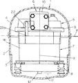
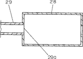
図19は本発明の実施例8による密閉型圧縮機の縦断面図を示す。図20は本発明の実施例8による密閉型圧縮機の吸入パイプの開口端部付近と吸入マフラーの断面図を示す。なお、実施例8の密閉型圧縮機において、前述の各実施例の密閉型圧縮機と同じ機能、構成を有するものには同じ符号を付して、その説明は省略する。
図19及び図20において、機械部6のシリンダー10の端面に固着されたバルブプレート19には吸入孔19aが形成されており、この吸入孔19aには吸入パイプ29の一端が直接接続されている。吸入パイプ29の他端には吸入マフラー28が設けられている。
次に、上記のように構成された実施例8の密閉型圧縮機について、その動作を説明する。
吸入行程時にサクションリード20が開くと同時に発生した圧力波は、バルブプレート19の吸入孔19aを通って冷媒ガスの流れと逆方向に伝播し、吸入マフラー28内の空間で位相の反転した反射波となる。この反射波は冷媒ガスの流れと順方向に伝播し、吸入孔19aに戻ってくる。
このとき、密閉容器2内の冷媒ガスが共鳴しているとしても、吸入パイプ29の開口端部29aが吸入マフラー28内にあるため、圧力波が吸入パイプ29の開口端部29aで反射する時に密閉容器2内の冷媒ガスの共鳴の影響を受けない。従って、実施例8の密閉型圧縮機は、圧力波が反射するときの圧力振幅の減衰を防ぐ。密閉容器2の形状や運転条件等の変化によって密閉容器2内の共鳴周波数がどのように変化しても、実施例8の密閉型圧縮機は、常に吸入圧力を上昇させ、冷凍能力の向上効果を得ることができる。
また、実施例8の密閉型圧縮機は、吸入マフラー28があるために、吸入される冷媒ガスの脈動が小さくなり、密閉容器2内の冷媒ガスを加振する力を小さくする。このため、実施例8の密閉型圧縮機は、密閉容器2内の冷媒ガスの共鳴周波数にかかわらず常に共鳴音を小さくする。
以上のように、実施例8の密閉型圧縮機は、吸入マフラー28と、一端が吸入マフラー28内に開口し他端が吸入孔19aに直結された吸入パイプ29とから構成されている。このため、実施例8の密閉型圧縮機は、吸入される冷媒ガスの脈動を小さくして密閉容器2内の冷媒ガスを加振する力を小さくし、密閉容器2内の冷媒ガスの共鳴周波数にかかわらず常に共鳴音を小さくすることができる。
また、実施例8の密閉型圧縮機は、密閉容器2内の冷媒ガスの共鳴周波数にかかわらず、常に圧力波が吸入パイプ29の開口部で反射する時の圧力振幅の減衰を防止する。このため、実施例8の密閉型圧縮機は、密閉容器2の形状や運転条件等のあらゆる変化にかかわらず、常に吸入圧力を上昇させ、冷凍能力の向上効果を得ることができる。
《実施例9》
次に、本発明の密閉型圧縮機の一例である実施例9について添付の図を用いて説明する。
図21は本発明の実施例9による密閉型圧縮機の縦断面図を示す。図22は図21の密閉型圧縮機のB−B線における平面断面図を示す。なお、実施例9の密閉型圧縮機において、前述の各実施例の密閉型圧縮機と同じ機能、構成を有するものには同じ符号を付して、その説明は省略する。
図21及び図22において、機械部6のシリンダー10の端面に固着されたバルブプレート19には吸入孔19aが形成されており、この吸入孔19aには吸入パイプ200の一端が直接接続されている。吸入パイプ200の他端は、開口端部200aとして密閉容器2内空間に配置されている。
吸入パイプ200は少なくともその一部がテフロンあるいはPBT等の熱伝導率の低い材料で形成されている。
次に、上記のように構成された実施例9の密閉型圧縮機について、その動作を説明する。
シリンダー10内で発生した圧力波は、バルブプレート19の吸入孔19aを通って、冷媒ガスの流れと逆方向に伝播し、密閉容器2内の空間で位相の反転した反射波となる。この反射波は冷媒ガスの流れと順方向に伝播し、吸入孔16aに戻ってくる。
吸入行程の間に、この反射波が吸入孔19aに到達させることにより、吸入完了時点で反射波の持つ圧力エネルギーが付加され、冷媒ガスの吸入圧力が上昇する。
そのため、シリンダー10内には、より密度の高い冷媒ガスが充填されることになり、圧縮1行程当たりの吐出冷媒量が増加する。この結果、実施例9の密閉型圧縮機は冷媒循環量が増加して、冷凍能力の大幅な向上が図られている。
実施例9の密閉型圧縮機は吸入パイプ200の少なくとも一部がテフロンあるいはPBT等の熱伝導率の低い材料で形成されているので、密閉型圧縮機の起動後の時間経過に伴いシリンダーヘッド80等の温度が大きく上昇しても、熱が吸入パイプ200に伝導するのを防止し、吸入パイプ200の温度変化を小さくすることができる。このため、実施例9の密閉型圧縮機は吸入パイプ200内の冷媒ガス中の音速変化を小さくすることができる。このため、実施例9の密閉型圧縮機は、安定した圧力波を発生させて吸入圧力の高い上昇効果を得ることができるとともに、起動後の時間経過に影響されず安定した高い冷凍能力を得ることができる。
実施例9の密閉型圧縮機は温度の低い冷媒ガスをシリンダー10内へ供給でき、冷媒循環量を向上させることができる。
以上のように、実施例9の密閉型圧縮機においては、吸入パイプ200の一端が密閉容器2内の空間に開口し、他端がバルブプレート19の吸入孔19aに直結され、かつ少なくとも一部がテフロンあるいはPBT等の熱伝導率の低い材料で形成されている。
このため、密閉型圧縮機の起動後の時間経過に伴いシリンダーヘッド80等の温度が大きく上昇しても、熱が吸入パイプ200を伝導することが防止され、吸入パイプ200の温度変化を小さくする。これにより、吸入パイプ200内の冷媒ガス中の音速変化を小さくすることができる。
この結果、実施例9の密閉型圧縮機は、安定した圧力波を発生させて吸入圧力の上昇を得ることができ、起動後の時間経過に影響されず安定した高い冷凍能力を得ることができる。
実施例9の密閉型圧縮機は、温度の低い冷媒ガスをシリンダー10内へ供給でき、冷媒循環量を向上させることができる。
なお、実施例9において、熱伝導率の低い材料で形成された吸入パイプを用いた密閉型圧縮機を示した。しかし、シリンダー部付近だけなどの部分的に熱伝導率の低い材料を用いても、上記実施例9と同様の効果が得られる。
《実施例10》
次に、本発明の密閉型圧縮機の一例である実施例10について添付の図を用いて説明する。
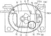
図23は本発明の実施例10による密閉型圧縮機の縦断面図を示す。図24は図23の密閉型圧縮機のC−C線における平面断面図を示す。図25は吸入圧力上昇比率変化を示す特性図である。図26は冷凍能力向上比率の変化を示す特性図である。図27は騒音変化率の変化を示す特性図である。なお、実施例10の密閉型圧縮機において、前述の各実施例の密閉型圧縮機と同じ機能、構成を有するものには同じ符号を付して、その説明は省略する。
図23及び図24において、機械部6のシリンダー10の端面に固着されたバルブプレート19には吸入孔19aが形成されており、この吸入孔19aには第1の吸入パイプ210の一端が直接接続されている。第1の吸入パイプ210の他端は、開口端部210aとして密閉容器2内空間に配置されており、吸入流路としての第2の吸入パイプ190の開口端部190aの近傍に配置されている。
次に、上記のように構成された実施例10の密閉型圧縮機について、その動作を説明する。
シリンダー10内で発生した圧力波は、バルブプレート19の吸入孔19aを通り、冷媒ガスの流れと逆方向に伝播し、密閉容器2内の空間で位相の反転した反射波となる。この反射波は、冷媒ガスの流れと順方向に伝播し、吸入孔19aに戻ってくる。
吸入行程の間に、この反射波が吸入孔19aに到達することにより、吸入完了時点で反射波の持つ圧力エネルギーが冷媒ガスに付加され、冷媒ガスの吸入圧力が上昇する。
そのため、シリンダー10内には、より密度の高い冷媒ガスが充填されることになり、圧縮1行程当たりの吐出冷媒量が増加し、冷媒循環量が増加する。この結果、実施例10の密閉型圧縮機は冷凍能力が大幅に向上したものとなる。
実施例10の密閉型圧縮機においては、密閉容器2内の第2の吸入パイプ190の開口端部190aの近傍に第1の吸入パイプ210の開口端部210aが配置されている。このため、実施例10の密閉型圧縮機は、温度が低く、密度の高い冷媒ガスを第1の吸入パイプ210内に吸入することができ、冷媒ガス中の音速が遅くなる。このため、実施例10の密閉型圧縮機は、圧縮性の影響が大きくなり、大きな圧力波を発生させることができる。
これにより、実施例10の密閉型圧縮機は、吸入圧力上昇効果を増加させることができる。そして、実施例10の密閉型圧縮機は、温度の低い冷媒ガスをシリンダー10内に吸入させることにより、冷凍能力の向上効果を大幅に増加させ、効率が良く高い冷凍能力を得ることができる。
実施例10の密閉型圧縮機は、第2の吸入パイプ190の開口端部190aと第1の吸入パイプ210の開口端部210aの間の隙間により、圧力脈動が第2の吸入パイプ190から冷凍サイクルへ伝わるのが低減される。このため、実施例10の密閉型圧縮機は、騒音を大幅に低減できる。
第1の吸入パイプ210の開口端部210aと第2の吸入パイプ190の開口端部190aとの間の距離(開口端部間距離)は、吸入圧力の上昇効果を大きく、冷凍能力の向上効果を大きく、そして騒音の低減効果を大きくするために、発明者の実験によれば3mmから50mmの間が好ましいことが明らかとなった。
この結果を図25、図26及び図27に示す。図25は縦軸に吸入圧力上昇比率(%)を示し、横軸に第2の吸入パイプ190の開口端部190aと第1の吸入パイプ210の開口端部210aとの間の隙間である開口端部間距離(mm)を示したグラフである。図25における吸入圧力上昇比率とは、シリンダー10内で発生した圧力波の圧力に対する、密閉容器2内の空間において圧力波が反射した反射波の圧力の比率を示す。
図26は縦軸に冷凍能力向上比率(%)を示し、横軸に開口端部間距離(mm)を示したグラフである。図26における冷凍能力向上比率とは、最大冷凍能力に対する測定された冷凍能力の比率である。
図27は縦軸に騒音変化率(%)をとり、横軸に開口端部間距離(mm)をとって示したものである。図27における騒音変化率とは、開口部間距離が0mmのときを100%としたときの騒音の圧力変化を示す。
以上のように、実施例10の密閉型圧縮機は、第1の吸入パイプ210の一端がバルブプレート19の吸入孔19aに直結されており、他端が密閉容器2内の第2の吸入パイプ190の開口端部190aの近傍に配置されている。このため、実施例10の密閉型圧縮機は、温度が低く、密度の高い冷媒ガスを第1の吸入パイプ210内に吸入することができるため、冷媒ガス中の音速を遅くすることができる。このために、実施例10の密閉型圧縮機は、圧縮性の影響が大きくなり、大きな圧力波を発生させることができる。このため、実施例10の密閉型圧縮機は、吸入圧力の上昇効果を増加させると共に、温度の低い冷媒ガスをシリンダー10内に吸入させることで、冷凍能力の向上効果を大幅に増加させ、高い冷凍能力を得ることができる。
実施例10の密閉型圧縮機は、第2の吸入パイプ190の開口端部190aと第1の吸入パイプ210の開口端部210aの間に隙間を形成することにより、圧力脈動が第2の吸入パイプ190から冷凍サイクルへ伝わるのを低減することができる。このため、実施例10の密閉型圧縮機は、騒音を大幅に低減することができる。
なお、第1の吸入流路としての第1の吸入パイプ210の開口端部210aを広くして、第2の吸入流路としての第2の吸入パイプ190の開口端部190aと相対向させることにより、冷媒ガスが流れやすくなり、冷凍能力の向上が図られることは言うまでもない。
《実施例11》
次に、本発明の密閉型圧縮機の一例である実施例11について添付の図を用いて説明する。
図28は本発明の実施例11による密閉型圧縮機の縦断面図を示す。図29は図28の密閉型圧縮機のD−D線における平面断面図を示す。図30は実施例11における第1の吸入パイプの開口端部の縦断面図を示す。図31は実施例11の第1の吸入パイプの開口端部の開口面を示す図である。
なお、実施例11の密閉型圧縮機において、前述の各実施例の密閉型圧縮機と同じ機能、構成を有するものには同じ符号を付して、その説明は省略する。
図28及び図29において、機械部6のシリンダー10の端面に固着されたバルブプレート19には吸入孔19aが形成されており、この吸入孔19aには第1の吸入パイプ220の一端が直接接続されている。第1の吸入パイプ220の他端は、開口端部220aとして密閉容器2内空間に配置されている。第2の吸入パイプ190はその開口端部190aが密閉容器2の内部空間に配置されている。
図29及び図30に示すように、第1の吸入パイプ220は、一端がバルブプレート19の吸入孔19aに直結され、他端が密閉容器2内の空間に開口する複数の開口端部220a、220bを持ち、かつ吸入孔19aから複数の開口端部220a、220bまでの長さが異なっている。
次に、上記のように構成された実施例11の密閉型圧縮機について、その動作を説明する。
シリンダー10内で発生した圧力波は、バルブプレート19の吸入孔19aを通り、冷媒ガスの流れと逆方向に伝播し、密閉容器2内の空間で位相の反転した反射波となる。この反射波は冷媒ガスの流れと順方向に伝播し、吸入孔19aに到達する。
吸入行程の間に、この反射波が吸入孔19aに到達することにより、吸入完了時点で反射波の持つ圧力エネルギーが冷媒ガスに付加され、吸入圧力が上昇する。
そのため、シリンダー10内には、より密度の高い冷媒ガスが充填されることになり、圧縮1行程当たりの吐出冷媒量が増加し、冷媒循環量が増加する。この結果、実施例11の密閉型圧縮機によれば、冷凍能力を大幅に向上させることができる。
このとき、吸入孔19aにおいて発生した圧力波は、吸入孔19aから開口端までの長さが異なる複数の開口端部220a、220bで次々反射し、吸入孔19aに到達して、シリンダー10内に供給される。
このことにより、実施例11の密閉型圧縮機は、吸入孔19aに反射波の到達するタイミングを広くとることができる。
従って、実施例11の密閉型圧縮機においては、運転条件の変化等により、冷媒ガス中の音速が変化し、1つの反射波の到達するタイミングがずれても、次々に他の反射波が吸入孔19aに到達する。このため、実施例11の密閉型圧縮機は、常にシリンダー10内に高い圧力の冷媒ガスを供給できる。
これにより、実施例11の密閉型圧縮機は、運転条件変化によらず常に吸入圧力を上昇させ安定した高い冷凍能力を得ることができる。
以上のように、実施例11の密閉型圧縮機は、第1の吸入パイプ220の一端がバルブプレート19の吸入孔19aに直結されており、他端が密閉容器2内の空間に開口し、かつ吸入孔19aから開口端までの長さが異なる複数の開口端部220a、220bを有している。このため、吸入孔19aにおいて発生した圧力波は、吸入孔19aから開口端までの長さが異なる複数の開口端部220a、220bで次々反射する。
この結果、実施例11の密閉型圧縮機は、吸入孔19aに反射波の戻るタイミングを広くとることができる。従って、実施例11の密閉型圧縮機においては、運転条件変化等により、冷媒ガス中の音速が変化し、1つの反射波の吸入孔19aに到達するタイミングがずれても、次々に他の反射波が吸入孔19aに到達する。このため、シリンダー10内には常に高い圧力の冷媒ガスが供給される。これにより、実施例11の密閉型圧縮機によれば、運転条件変化によらず常に吸入圧力を上昇させ安定した高い冷凍能力を得ることができる。
なお、実施例11においては、吸入流路として長さの異なる複数の開口端部220a,220bを有する吸入パイプ220を用いたが、長さの異なる複数本の吸入パイプとしても上記実施例11と同様の効果を得られる。
《実施例12》
次に、本発明の密閉型圧縮機の一例である実施例12について添付の図を用いて説明する。
図32は本発明の実施例12による密閉型圧縮機を示す縦断面図である。図33は図32の密閉型圧縮機のE−E線における平面断面図である。図34は実施例12における起動時のシリンダーヘッド部分の要部を示す平面断面図である。図35は実施例12における安定運転時のシリンダーヘッド部分の要部を示す平面断面図である。
なお、実施例12の密閉型圧縮機において、前述の各実施例の密閉型圧縮機と同じ機能、構成を有するものには同じ符号を付して、その説明は省略する。
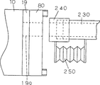
図32及び図33において、機械部6のシリンダー10の端面に固着されたバルブプレート19には吸入孔19aが形成されており、この吸入孔19aには第1の吸入パイプ230の一端が連通パイプ240を介して接続されるよう構成されている。第1の吸入パイプ230の他端は、開口端部230aとして密閉容器2内空間に配置されている。第2の吸入パイプ190はその開口端部が密閉容器2の内部空間に配置されている。
図33及び図34に示すように、第1の吸入パイプ230は、その一端が密閉容器2内の空間に開口しており、他端がバルブプレート19の吸入孔19aに直結されておらず、シリンダーヘッド80の手前で切断された状態である。切断された第1の吸入パイプ230は連通パイプ240によりシリンダーヘッド80の開口穴80aと連通可能に配置されている。
図34及び図35に示すように、吸入パイプ230と連通パイプ240との間にベローズ250が設けられている。すなわちベローズ250の一端が第1の吸入パイプ230に固定され、他端が連通パイプ240に固定されている。実施例12において、連通パイプ240とベローズ250により連通遮断機構が形成されている。
次に、上記のように構成された実施例12の密閉型圧縮機について、その動作を説明する。
シリンダー10内で発生した圧力波は、バルブプレート19の吸入孔19aを通り、冷媒ガスの流れと逆方向に伝播し、密閉容器2内の空間で位相の反転した反射波となる。この反射波は、冷媒ガスの流れと順方向に伝播して、吸入孔19aに戻ってくる。
吸入行程の間に、この反射波が吸入孔19aに到達させることにより、吸入完了時点で反射波の持つ圧力エネルギーが冷媒ガスへ付加され、吸入圧力が上昇する。
そのため、シリンダー10内には、より密度の高い冷媒ガスが充填されることにより、圧縮1行程当たりの吐出冷媒量が増加し、冷媒循環量が増加する。この結果、実施例12の密閉型圧縮機は冷凍能力を大幅に向上させることができる。
しかしながら、圧力波は起動時にも発生するため、起動トルクが大きくなり、モーター部7の能力向上を必要とした。
そこで、図34に示すように、起動時等の密閉容器2内の圧力が高い場合、ベローズ250は押し縮められ、連通パイプ240はシリンダーヘッド80から離れる。
これにより、第1の吸入パイプ230は吸入孔19aと連通しなくなり、圧力波は発生しなくなる。従って、冷凍能力向上効果はなくなるが、トルクを大幅に低減し、起動不良が防止でき、信頼性の向上を図ることができる。
一方、図35に示すように、起動後に密閉容器2内の圧力が低下すると、ベローズ250は引き延ばされ、連通パイプ240はシリンダーヘッド80に圧着される。
これにより、第1の吸入パイプ230は吸入孔19aと連通し、圧力波が発生し、吸入圧力の上昇効果を得ることができる。このため、実施例12の密閉型圧縮機は冷凍能力の向上が図られている。
以上のように、実施例12の密閉型圧縮機は、第1の吸入パイプ230の一端が密閉容器1内の空間に開口し、他端がバルブプレート19の吸入孔19aに直結されており、第1の吸入パイプ230がシリンダーヘッド80の手前で切断されている。そして、連通パイプ240を設けて、切断された第1の吸入パイプ230とシリンダーヘッド80の開口穴80aとを連通可能に構成し、連通遮断機構のベローズ250の一端を第1の吸入パイプ230に固定し、他端を連通パイプ240に固定している。
従って、起動時等の密閉容器2内の圧力が高い場合、ベローズ250は押し縮められ、連通パイプ240はシリンダーヘッド80から離れる。このため、第1の吸入パイプ230は吸入孔19aと連通しなくなり、圧力波は発生しなくなる。その結果、実施例12の密閉型圧縮機においては、起動時等の密閉容器2内の圧力が高い場合、冷凍能力の向上は図られないが、トルクを大幅に低減して、起動不良が防止でき、信頼性を向上することができる。
一方、実施例12の密閉型圧縮機においては、起動後、密閉容器2内の圧力が低下すると、ベローズ250は引き延ばされ、連通パイプ240はシリンダーヘッド80に圧着される。このため、第1の吸入パイプ230は吸入孔19aと連通し、圧力波が発生し、吸入圧力の上昇効果を得ることができ、冷凍能力の向上が図られる。
なお、実施例12において、連通遮断機構をベローズ250により構成したが、起動時において第1の吸入パイプ230を連通させない機構であれば、上記実施例12と同様の効果が得られることは言うまでもない。
また、実施例12において、連通遮断機構としたが、起動時に圧力波を発生させない機構であれば、上記実施例12と同様の効果が得られることは言うまでもない。
《実施例13》
次に、本発明の密閉型圧縮機の一例である実施例13について添付の図を用いて説明する。
図36は本発明の実施例13の密閉型圧縮機のピストンの往復方向を含む水平面における当該往復方向と直角の方向に共鳴モードの節部を持つ時の平面断面図である。図37は実施例13の密閉型圧縮機におけるピストンの往復方向を含む水平面における当該往復方向と直角の方向に共鳴モードの節部を持つ時の正面図である。
なお、実施例13の密閉型圧縮機において、前述の各実施例の密閉型圧縮機と同じ機能、構成を有するものには同じ符号を付して、その説明は省略する。
図36及び図37において、機械部6のシリンダー10の端面に固着されたバルブプレート211には吸入孔211aが形成されており、この吸入孔211aは吸入室251を介して第1の吸入パイプ241(吸入流路)の一端に接続されている。第1の吸入パイプ241の他端は、開口端部241aとして密閉容器2内空間に配置されている。
上記のように、吸入流路としての第1の吸入パイプ241は、その一端が密閉容器2内に開口し、他端が空間としての吸入室251を介してバルブプレート211の吸入孔211aに連結している。第1の吸入パイプ241の密閉容器2内の開口端部241aは、下記3つの平面の少なくとも1つ以上の平面上に配置される。
(1)前記密閉容器2の水平断面(図36の紙面に平行な断面)にてその断面積が実質的に最大となる面(図37の直線Hにて示す水平面)の重心(水平断面部分における重心の位置)を通る第1の線分(図36の矢印vにて示す線分)であり、かつ当該第1の線分(v)が(図37の直線Hにて示す水平面における)前記密閉容器2の内壁面間の距離が最小となる位置にあり、前記第1の線分(v)の中心点において前記第1の線分(v)と実質的に直交する第1の平面(図36の直線Wにて示す平面)上(図36において開口端部241aを示した位置)、又は
(2)前記第1の線分(v)を含む水平面(H)において、前記第1の線分(v)と実質的に直交する前記密閉容器2の内壁面間の第2の線分(図36の矢印wにて示す線分)の中心点を通り、かつ前記第2の線分(w)と実質的に直交する第2の平面(図36の直線Vにて示す鉛直平面)上、又は
(3)前記密閉容器2の鉛直方向における内壁上面と前記潤滑油17の油面との間の最大距離となる第3の線分(図37の矢印xにて示す線分)の中心点を通り、かつ前記第3の線分(x)と実質的に直交する第3の平面(図37の直線Yにて示す水平面)上、
の3つの平面の少なくとも1つの平面上に第1の吸入パイプ241の開口端部241aが配置されている。
図36及び図37に示す密閉型圧縮機は、第1の吸入パイプ241の開口端部241aが第1の平面(W)上に配置されている場合である。
図36及び図37に示すように、第1の吸入パイプ241の開口端部241aの近傍には第2の吸入パイプ260の開口端部260aが配設されている。この第2の吸入パイプ260は密閉容器2の外部の冷凍システムから冷媒ガスを吸入するよう構成されている。
次に、上記のように構成された実施例13の密閉型圧縮機について、その動作を説明する。
冷凍冷蔵装置等の冷凍システムから循環してきた冷媒ガスは、第2の吸入パイプ260を通り、密閉容器2内空間に一旦開放される。一旦開放された冷媒ガスは、第1の吸入パイプ241及び吸入室251を介してシリンダー10内に吸入され、ピストン11により圧縮される。その際、冷媒ガスはクランクシャフト12の1/2回転でシリンダー10内に吸入され、後の1/2回転で圧縮される。そのため、冷媒ガスは連続的にシリンダー10内に吸入されず、第1の吸入パイプ241に冷媒ガスの圧力脈動が生じる。従って、その圧力脈動が密閉容器2内の空間を加振し、ピストン11の往復方向、ピストン11の往復方向を含む水平面における当該往復方向と直角の方向、クランクシャフト12の軸方向に共鳴モードが生じてしまう。
しかし、実施例13の密閉型圧縮機においては、第1の吸入パイプ241の密閉容器2内空間への開口端部241aを、図36において距離aで示される線分(v)の中心点を通り、かつその線分(v)に直角となる平面上に配置されている。すなわち、実施例13の密閉型圧縮機は、ピストン11の往復方向を含む水平面における当該往復方向と直角の方向に生じた共鳴モードの節部のある平面上としている。このため、共鳴モードを励起する圧力脈動成分は、共鳴モードの節部に位置することになる。従って、共鳴モードの節部にて加振することとなり、共鳴モードは励起されず、共鳴音の発生を抑えることができる。
さらに、実施例13の密閉型圧縮機においては、第2の吸入パイプ260の密閉容器2内の開口端部260aを第1の吸入パイプ241の密閉容器2内の開口端部241aの近傍に設けることにより、第1の吸入パイプ241へ吸入される冷媒ガスが密閉容器2内の冷媒ガスにより加熱されることを防ぐことができる。このため、シリンダー10内には、より密度の高い冷媒ガスが充填されることになり、実施例13の密閉型圧縮機においては、圧縮1行程当たりの吐出冷媒量が増し、冷媒循環量が増加し、冷凍能力を向上させることができる。
以上のように、本実施例13の密閉型圧縮機は、クランクシャフト12、ピストン11、シリンダー10等の機械部6と、モーター部7と、下部に潤滑油17を貯溜する密閉容器2と、吸入孔211aを有しシリンダー10の端面に配設されたバルブプレート211と、第1の吸入パイプ241と、第2の吸入パイプ260とを有している。第1の吸入パイプ241の一端は吸入室251の空間を介してバルブプレート211の吸入孔211aに連結されており、他端の開口端部241aは密閉容器2内の所望の位置に配設されている。すなわち、開口端部241aは、
(1)密閉容器2の水平断面にて断面積が略最大となる平面上の重心を通り、かつ密閉容器2の内壁面間の距離が最小となる第1の線分(v:距離a)に対してその中心点を通り、かつ第1の線分(v)に略直角となる平面(W)上、又は
(2)水平断面の重心を通る距離が最小となる第1の線分vを含む水平面上にて略直角となる密閉容器2の内壁面間の第2の線分(w:距離b)に対してその中心点を通り、かつその第2の線分(w)に略直角となる平面(V)上、又は
(3)密閉容器2の鉛直方向の内壁上面と潤滑油17の油面との間の最大距離となる第3の線分(x:距離c)に対しその中心点を通り、かつその第3の線分(x)に略直角となる平面(Y)上、
の3つの平面の少なくとも1つの平面上に吸入流路の密閉容器内の吸入口として配置される。
そして、第2の流入パイプ260は、その一端が密閉容器2外へ導出され、他端が開口端部260aとして密閉容器2内に配置され、この開口端部260aが吸入流路としての第1の吸入パイプ241の開口端部241aの近傍に設けられている。
このため、実施例13の密閉型圧縮機は、密閉容器2内に生じる共鳴を防止し、共鳴音の発生による騒音増加を防止することができる。そして、実施例13の密閉型圧縮機は、冷媒ガスの密度を高め、冷凍能力を向上させることができる。
なお、実施例13においては、吸入流路としての第1の吸入パイプ241の密閉容器2内空間の開口端部241aを、ピストン11の往復方向を含む水平面における当該往復方向と直角の方向の共鳴モードの節部として説明した。しかし、吸入パイプ241の密閉容器2内空間の開口端部241aが、ピストン11の往復方向の共鳴モードの節部、またはクランクシャフト12の軸方向の共鳴モードの節部など、吸入流路2の密閉容器2内空間への開口端部が問題となる共鳴モードの節部に配置されていれば、上記実施例13と同様の効果を奏する。
実施例13では、吸入流路が吸入パイプ241と空間としての吸入室251として説明した。しかし、空間を有する吸入流路としてマフラー等が付加されている場合でも上記実施例13と同様の効果が得られる。
実施例13の密閉型圧縮機は、シリンダー10の数量が1個の場合で説明した。しかし、本発明は複数のシリンダーを有する密閉型圧縮機にも適用できる。
本発明の密閉型圧縮機は、吸入流路が2つ以上ある場合でも、それぞれの吸入流路の密閉容器2内への開口端部を上記実施例13に示した共鳴モードの節部の位置に配設することにより、上記実施例13と同様の効果が得られる。
《実施例14》
次に、本発明の密閉型圧縮機の一例である実施例14について添付の図を用いて説明する。
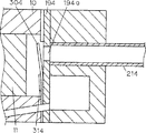
図38は、本発明の実施例14による密閉型圧縮機において、ピストン11の往復方向を含む水平面における当該往復方向と直角の方向に共鳴モードの節部を持つ時の縦断面図である。図39は実施例14の密閉型圧縮機のピストンの往復方向を含む水平面における当該往復方向と直角の方向に節部を持つ時の平面断面図である。
なお、実施例14の密閉型圧縮機において、前述の各実施例の密閉型圧縮機と同じ機能、構成を有するものには同じ符号を付して、その説明は省略する。
図38及び図39において、機械部6のシリンダー10の端面に固着されたバルブプレート211には吸入孔211aが形成されており、この吸入孔211aは第1の吸入パイプ271(吸入流路)の一端に直接接続されている。第1の吸入パイプ271の他端は、開口端部271aとして密閉容器2内空間の所定の位置に配置されている。
吸入流路である第1の吸入パイプ271の密閉容器2内の開口端部271aは、下記3つの平面の少なくとも1つ以上の平面上に配置されるよう構成されている。
(1)前記密閉容器2の水平断面(図37の紙面に平行な断面)にてその断面積が実質的に最大となる面(図38の直線Hにて示す水平面)の重心(水平断面部分における重心の位置)を通る第1の線分(図39の矢印vにて示す線分)であり、かつ当該第1の線分(v)が(図38の直線Hにて示す水平面において)前記密閉容器2の内壁面間の距離が最小となる位置にあり、前記第1の線分(v)の中心点において前記第1の線分(v)と実質的に直交する第1の平面(図39の直線Wにて示す平面)上(図39において、開口端部271aを示した位置)、又は
(2)前記第1の線分(v)を含む水平面(H)において、前記第1の線分(v)と実質的に直交する前記密閉容器2の内壁面間の第2の線分(図39の矢印wにて示す線分)の中心点を通り、かつ前記第2の線分(w)と実質的に直交する第2の平面(図39の直線Vにて示す鉛直平面)上、又は
(3)前記密閉容器2の鉛直方向における内壁上面と前記潤滑油17の油面との間の最大距離となる第3の線分(図38の矢印xにて示す線分)の中心点を通り、かつ前記第3の線分(x)と実質的に直交する第3の平面(図38の直線Yにて示す水平面)上、
の3つの平面の少なくとも1つの平面上に第1の吸入パイプ271の開口端部271aが配置されている。
図38及び図39に示す実施例14の密閉型圧縮機は、第1の吸入パイプ271の開口端部271aが第1の平面(W)上に配置されている場合である。
図38及び図39に示すように、第1の吸入パイプ271の開口端部271aの近傍には第2の吸入パイプ281の開口端部281aが配設されている。この第2の吸入パイプ281は密閉容器2の外部に導出している。
次に、上記のように構成された実施例14の密閉型圧縮機について、その動作を説明する。
バルブプレート211の近傍で発生した圧力波は、吸入孔211aを通り冷媒ガスの流れと逆方向に伝播し、密閉容器2内の空間で位相の反転した反射波となる。この反射波は冷媒ガスの流れと順方向に伝播し、吸入孔211aに戻ってくる。
この反射波が吸入孔211aに到達する時点と、シリンダー10内の容積が最大になる時点(吸入完了時点)とを一致させることにより、吸入完了時点で反射波の持つ圧力エネルギーが冷媒ガスに付加され、冷媒ガスの吸入圧力が上昇する。
そのため、シリンダー10内には、より密度の高い冷媒ガスが充填されることになり、圧縮1行程当たりの吐出冷媒量が増加し、冷媒循環量が増加する。このため、実施例14の密閉型圧縮機は冷凍能力の大幅に向上した装置となる。
冷凍冷蔵装置等のシステムから循環してきた第2の吸入パイプ281の冷媒ガスは、いったん密閉容器2内空間に開放され、バルブプレート211に固定された第1の吸入パイプ271を介してシリンダー10内に吸入され、ピストン11により圧縮される。その際、冷媒ガスはクランクシャフト12の1/2回転でシリンダー10内に吸入され、後の1/2回転で圧縮される。
このように冷媒ガスは連続的にシリンダー10内に吸入されないため、第1の吸入パイプ271に冷媒ガスの圧力脈動が生じる。従って、その圧力脈動が密閉容器2内の空間を加振し、ピストン11の往復方向、ピストン11の往復方向を含む水平面における当該往復方向と直角の方向、及びクランクシャフト12の軸方向に共鳴モードが発生する。
しかし、第1の吸入パイプ271の密閉容器2内空間の開口端部271aを、上記のように、距離a(図39)により示される線の中心点を通り、かつその線と直交する平面(W)上、すなわちピストン11の往復方向を含む水平面における当該往復方向と直角の方向における共鳴モードの節部の位置を含む平面上に配置している。このため、共鳴モードを励起する圧力脈動成分は、共鳴モードの節部に集中することになる。
従って、実施例14の密閉型圧縮機においては、圧力脈動が共鳴モードの節部を加振することになる。このため、この密閉型圧縮機においては、共鳴モードが励起されず、共鳴音の発生を抑えることができ、共鳴音により密閉型圧縮機の騒音が抑制されている。
さらに、実施例14の密閉型圧縮機では、第2の吸入パイプ281の密閉容器2内の開口端部281aを第1の吸入パイプ271の密閉容器2内の開口端部271aの近傍に設けられている。このため、実施例14の密閉型圧縮機は、第1の吸入パイプ271へ吸入される冷媒ガスが密閉容器2内の冷媒ガスにより加熱されることを防ぐことができる。そして、実施例14の密閉型圧縮機は、冷媒ガス中の音速が減少するため、圧縮能力が大きくなり、大きな圧力波が発生し、冷媒ガスの吸入圧力が大幅に上昇する。
実施例14の密閉型圧縮機は、以上のように構成されているため、シリンダー10内に、より密度の高い冷媒ガスが充填されることになり、圧縮1行程当たりの吐出冷媒量が増加する。このため、実施例14の密閉型圧縮機は、冷媒循環量が増加し、冷凍能力を大幅に向上させることができる。
なお、実施例14においては、吸入流路としての第1の吸入パイプ271が、その開口端部271aをピストン11の往復方向を含む水平面における当該往復方向と直角の方向の共鳴モードの節部に配置した構成とした。しかし、第1の吸入パイプ271の開口端部271aは、ピストン11の往復方向の共鳴モードの節部、またはクランクシャフト12の軸方向の共鳴モードの節部など、吸入流路の密閉容器2内空間への開口端が問題となる共鳴モードの節部の位置に配置されていればよい。
本発明の実施例14はシリンダー10の数にこだわらず適用できる。更に、吸入流路が2つ以上ある場合でも、それぞれの吸入流路の密閉容器2内への開口端を上記に示した共鳴モードの節部の位置に配置することにより、上記実施例14と同様の効果が得られる。
吸入流路としての第1の吸入パイプ271がバルブプレート211の吸入孔211aへわずかな空間(断面形状が実質的に同じである空間)を介して連結される構成であっても、上記実施例14とほぼ同等の効果が得られる。
以上のように、実施例14によれば、密閉容器内に生じる共鳴を防止し、共鳴音による密閉型圧縮機の騒音増加を防止することができる。そして、実施例14の密閉型圧縮機は、冷媒ガスの密度を高め、冷凍能力を向上させることができるという有利な効果が得られる。
実施例14によれば、吸入流路の密閉容器内への開口端が共鳴モードの節部となり、吸入流路の圧力波により発生する衝撃音の発生を大幅に低減し、密閉型圧縮機の騒音増加を防止することができる。このため、実施例14の密閉型圧縮機は、冷媒ガスの密度を高め、冷凍能力を大幅に向上させることができるという有利な効果が得られる。
《実施例15》
次に、本発明の密閉型圧縮機の一例である実施例15について添付の図を用いて説明する。
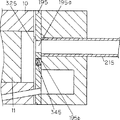
図40は本発明の実施例15による密閉型圧縮機を示す縦断面図である。図41は図40の密閉型圧縮機のB−B線における正面断面図である。図42は実施例15による別の吸入流路形状を有する密閉型圧縮機を示す縦断面図である。図43は図42の密閉型圧縮機のC−C線における正面断面図である。
なお、実施例15の密閉型圧縮機において、前述の各実施例の密閉型圧縮機と同じ機能、構成を有するものには同じ符号を付して、その説明は省略する。
図40及び図41において、機械部6のシリンダー10の端面に固着されたバルブプレート191には吸入孔191aが形成されており、この吸入孔191aは第1の吸入パイプ201(吸入流路)の一端に直接接続されている。第1の吸入パイプ201の他端は、開口端部201aとして密閉容器2内空間の所定の位置に配置されている。第1の吸入パイプ201(吸入流路)は、ほぼ均一な曲率の曲げ部201bを有している。
次に、上記のように構成された実施例15の密閉型圧縮機について、その動作を説明する。
吸入行程時にバルブプレート191の吸入孔191a付近で発生した圧力波は、冷媒ガスの流れと逆方向に伝播し、密閉容器2内の空間で位相の反転した反射波となり、冷媒ガスの流れと順方向に伝播し、吸入孔191aに戻ってくる。
吸入行程の間に、この反射波が吸入孔191aに到達させることにより、吸入完了時点での反射波の持つ圧力エネルギーが冷媒ガスに付加され、冷媒ガスの吸入圧力が上昇する。
そのため、実施例15の密閉型圧縮機においては、シリンダー10内に、より密度の高い冷媒ガスが充填されることになり、圧縮1行程当たりの吐出冷媒量が増加し、冷媒循環量が増加して、冷凍能力を向上させることができる。
また、実施例15の密閉型圧縮機は、第1の吸入パイプ201の各曲げ部201bの曲率をほぼ均一にすることで、曲げ部201bにおける圧力波の振幅の減少を抑制し、圧力の高い反射波をシリンダー10内に戻すことができ、より高い冷凍能力の向上を図ることができる。
また、実施例15の密閉型圧縮機は、第1の吸入パイプ201をコンパクトに形成でき、密閉容器2の小型化を達成できる。
以上のように、実施例15の密閉型圧縮機は、吸入孔191aを有しシリンダー10の端面に配設されたバルブプレート191と、一端が密閉容器2内の空間に開口し、他端がバルブプレート191の吸入孔191aにほぼ直結され、かつほぼ均一な曲率の曲げ部201bを有する第1の吸入パイプ201とを具備している。このため、実施例15の密閉型圧縮機は、圧力波や反射波の圧力振幅の減衰を低減することができる。そのため、実施例15の密閉型圧縮機は、吸入圧力を上昇させ、高い冷凍能力を得ることができる。
実施例15の密閉型圧縮機においては、吸入流路である第1の吸入パイプを図42及び図43に示すような、らせん状の吸入パイプ212に形成することにより、曲げ部212bの曲率を大きくとることができる。このため、実施例15の密閉型圧縮機は、第1の吸入パイプ212内の圧力の減衰をさらに低減できる。
なお、実施例15において、第1の吸入パイプ201、212がバルブプレート191の吸入孔191aにほぼ直結する構成とした。しかし、第1の吸入パイプ201、212とバルブプレート191の吸入孔191aとを断面積が実質的に等しい流路空間を介して連結しても上記実施例15と同等の効果が得られる。
実施例15の密閉型圧縮機において、吸入流路を管状の第1の吸入パイプ201、212により構成した。しかし、吸入パイプに代えて、例えば吸入流路を有するブロック状のものにより吸入流路を構成しても上記実施例15と同様の効果を得ることができる。
《実施例16》
次に、本発明の密閉型圧縮機の一例である実施例16について添付の図を用いて説明する。
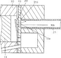
図44は本発明の実施例16による密閉型圧縮機を示す縦断面図である。図45は図44の密閉型圧縮機のD−D線における正面断面図である。
なお、実施例16の密閉型圧縮機において、前述の各実施例の密閉型圧縮機と同じ機能、構成を有するものには同じ符号を付して、その説明は省略する。
図44及び図45において、機械部6のシリンダー10の端面に固着されたバルブプレート192には吸入孔192aが形成されており、この吸入孔192aは第1の吸入パイプ221(吸入流路)の一端に直接接続されている。第1の吸入パイプ221の他端は、開口端部221aとして密閉容器2内空間の所定の位置に配置されている。図45に示すように、第1の吸入パイプ221(吸入流路)は、吸入流路間が近接するように複数回曲げられている。
次に、上記のように構成された実施例16の密閉型圧縮機について、その動作を説明する。
吸入行程時にバルブプレート192の吸入孔192a付近で発生した圧力波は、冷媒ガスの流れと逆方向に伝播し、密閉容器2内の空間で位相の反転した反射波となり、冷媒ガスの流れと順方向に伝播し、吸入孔192aに戻ってくる。
吸入行程の間に、この反射波が吸入孔192aに到達させることにより、吸入完了時点での反射波の持つ圧力エネルギーが冷媒ガスに付加され、冷媒ガスの吸入圧力が上昇する。
そのため、実施例16の密閉型圧縮機においては、シリンダー10内に、より密度の高い冷媒ガスが充填されることになり、圧縮1行程当たりの吐出冷媒量が増加し、冷媒循環量が増加して、冷凍能力を向上させることができる。
実施例16の密閉型圧縮機においては、第1の吸入パイプ221を複数回曲げ、内部に低温の吸入ガスが流れる吸入パイプ221を近接させて配置している。このため、実施例16の密閉型圧縮機は、密閉容器2内の圧縮発熱、モーター発熱、摺動発熱等の影響で高温となっている密閉容器2内の冷媒ガスの影響を少なくすることができる。
これにより、実施例16の密閉型圧縮機は、密閉容器2内の高温の冷媒ガスの熱が第1の吸入パイプ221に伝わることが抑制され、第1の吸入パイプ221内の吸入ガスの温度の上昇を低減させることができる。この結果、実施例16の密閉型圧縮機は、吸入ガスの密度を高め、冷媒循環量を増加させることができる。
実施例16の密閉型圧縮機は、吸入される冷媒ガスの温度(吸入ガス温度)が低く、密度の高い冷媒ガスが吸入パイプ221内に吸入される。これにより、吸入ガスの音速が遅くなるため、冷媒ガスの圧縮性の効果が大きくなり、大きな圧力波が発生し、高い冷凍能力を得ることができる。
また、実施例16の密閉型圧縮機は、第1の吸入パイプ221をコンパクトに形成でき、密閉容器を小型化できる。
以上のように、実施例16の密閉型圧縮機は、吸入孔191aを有しシリンダー10の端面に配設されたバルブプレート191と、一端が密閉容器2内の空間に開口し、他端がバルブプレート191の吸入孔191aにほぼ直結され、かつ吸入流路間が近接するように複数回曲げられた第1の吸入パイプ221とを備えたものである。このため、実施例16の密閉型圧縮機は、第1の吸入パイプ221が密閉容器1内の高温の冷媒ガスから受ける熱量を小さくし、第1の吸入パイプ221の温度上昇を低減し、第1の吸入パイプ221内の吸入ガス温度の上昇を低減させている。この結果、実施例16の密閉型圧縮機は、大きな冷媒循環量を得ることができる。
それと共に、実施例16の密閉型圧縮機は、吸入ガス温度が低く、密度の高い冷媒ガスを第1の吸入パイプ221内に吸入することにより、吸入される冷媒ガス中の音速が遅くなる。このため、実施例16の密閉型圧縮機は、冷媒ガスの圧縮性の影響が大きくなり、大きな圧力波が発生し、高い冷凍能力の向上効果を得ることができる。
なお、実施例16において、第1の吸入パイプ221を複数回曲げて吸入流路間を近接させ、第1の吸入パイプ221が高温の密閉容器内の冷媒ガスから受ける熱量を減らす構成としたが、例えば近接した吸入流路を有するブロック状のものでも上記実施例16の密閉型圧縮機と同様の効果が得られる。
実施例16において、第1の吸入パイプ221どうしを近接させる構成とした。しかし、第1の吸入パイプ221どうしを密着させることにより、第1の吸入パイプ221と高温の密閉容器内の冷媒ガスとの熱交換面積を減少させてもよい。このように構成することにより、本発明の密閉型圧縮機は、第1の吸入パイプ221の受熱量が低減でき、さらに、高い冷凍能力の向上効果を得ることができる。
実施例16において、第1の吸入パイプ221をバルブプレート191の吸入孔191aにほぼ直結させる構成とした。しかし、第1の吸入パイプ221とバルブプレート191の吸入孔191aとを断面積が実質的に等しい流路空間を介して連結してもほぼ同等の効果が得られる。
《実施例17》
次に、本発明の密閉型圧縮機の一例である実施例17について添付の図を用いて説明する。
図46は本発明の実施例17による密閉型圧縮機を示す縦断面図である。図47は図46の密閉型圧縮機のE−E線における正面断面図である。
なお、実施例17の密閉型圧縮機において、前述の各実施例の密閉型圧縮機と同じ機能、構成を有するものには同じ符号を付して、その説明は省略する。
図46及び図47において、機械部6のシリンダー10の端面に固着されたバルブプレート193には吸入孔193aが形成されており、この吸入孔193aは第1の吸入パイプ231(吸入流路)の一端に直接接続されている。第1の吸入パイプ231の他端は、開口端部231aとして密閉容器2内空間の所定の位置に配置されている。図47に示すように、第1の吸入パイプ231(吸入流路)は、吸入流路間が近接するように複数回曲げられている。
図47に示すように、実施例17の密閉型圧縮機には吸入マフラー241が設けられている。この吸入マフラー241は第1の吸入パイプ231をほぼ包み込むよう構成されている。吸入マフラー241は、圧力波を反射するのに必要な容積を有している。
次に、上記のように構成された実施例17の密閉型圧縮機について、その動作を説明する。
吸入行程時にバルブプレート193の吸入孔193a付近で発生した圧力波は、冷媒ガスの流れと逆方向に伝播し、密閉容器2内の空間で位相の反転した反射波となり、冷媒ガスの流れと順方向に伝播し、吸入孔193aに戻ってくる。
吸入行程の間に、この反射波が吸入孔193aに到達させることにより、吸入完了時点での反射波の持つ圧力エネルギーが冷媒ガスに付加され、冷媒ガスの吸入圧力が上昇する。
そのため、実施例17の密閉型圧縮機においては、シリンダー10内に、より密度の高い冷媒ガスが充填されることになる。このため、実施例17の密閉型圧縮機は、圧縮1行程当たりの吐出冷媒量が増加し、冷媒循環量が増加して、冷凍能力を向上させることができる。
このとき、実施例17の密閉型圧縮機は、第1の吸入パイプ231の開口端部231aは吸入マフラー241内に配設されている。このため、実施例17の密閉型圧縮機においては、吸入ガスの脈動が吸入マフラー241で減衰され、密閉容器2内の冷媒ガスを加振する力を小さくし、密閉容器2内の冷媒ガスの共鳴周波数にかかわらず、常に共鳴音を小さくすることができる。
実施例17の密閉型圧縮機においては、密閉容器2内の冷媒ガスが共鳴しているとしても、第1の吸入パイプ231の開口端部231aが吸入マフラー241内にあるために、圧力波が吸入第1の吸入パイプ231の開口端部231aで反射する時に密閉容器2内の冷媒ガスの共鳴の影響を受けない。
従って、実施例17の密閉型圧縮機は、圧力波が第1の吸入パイプ231の吸入マフラー241内の開口端部241aで反射する時に密閉容器2空間内の共鳴の影響を受けて圧力振幅が減衰するのを防止する。このため、実施例17の密閉型圧縮機は、密閉容器2の形状や運転条件等におけるあらゆる変化にもかかわらず、冷媒ガスの吸入圧力が常に上昇し、安定した高い冷凍能力を得ることができる。
実施例17の密閉型圧縮機では、第1の吸入パイプ231を吸入マフラー241で囲うことにより、第1の吸入パイプ231の温度分布を均一化し、冷媒ガス中の音速変化を小さくすることができる。このため、実施例17の密閉型圧縮機は、圧力波の減衰を小さくして、安定した冷媒ガスの吸入圧力の上昇を得ることができ、安定した冷凍能力の向上効果を得ることができる。
実施例17の密閉型圧縮機においては、第1の吸入パイプ231をコンパクトに形成でき、密閉容器2を小型化することができる。
以上のように、実施例17の密閉型圧縮機は、吸入孔191aを有しシリンダー10の端面に配設されたバルブプレート191と、一端が密閉容器2内の空間に開口し、他端がバルブプレート191の吸入孔191aにほぼ直結された第1の吸入パイプ231と、第1の吸入パイプ231をほぼ包み込む吸入マフラー241とを具備している。このため、実施例17の密閉型圧縮機は、吸入ガスの脈動を小さくして密閉容器2内の冷媒ガスを加振する力を小さくし、密閉容器2内の冷媒ガスの共鳴周波数にかかわらず、常に共鳴音を小さくすることができる。
実施例17の密閉型圧縮機は、密閉容器2内の冷媒ガスの共鳴周波数にかかわらず、圧力波が第1の吸入パイプ231の開口端部231aで反射する時の圧力振幅の減衰を常に防ぐことができる。実施例17の密閉型圧縮機は、密閉容器2の形状や運転条件等のあらゆる変化にかかわらず、常に冷媒ガスの吸入圧力が上昇し、安定した高い冷凍能力を得ることができる。
実施例17の密閉型圧縮機は、第1の吸入パイプ231の温度分布を均一化し、冷媒ガス中の音速変化を小さくすることができる。このため、実施例17の密閉型圧縮機は、圧力波の減衰を小さくし安定した吸入圧力の上昇を得ることで、安定した冷凍能力を得ることができる。
なお、実施例17において、第1の吸入パイプ231がバルブプレート191の吸入孔191aにほぼ直結した構成とした。しかし、第1の吸入パイプ231とバルブプレート191の吸入孔191aとをわずかな空間(実質的に同じ断面形状を有する流路空間)を介して連結しても上記実施例17とほぼ同等の効果が得られる。
実施例17において、吸入流路を管状の第1の吸入パイプ231として説明した。しかし、例えば吸入流路が形成されたブロック状のものでも、上記実施例17と同様の効果を得ることができる。
《実施例18》
次に、本発明の密閉型圧縮機の一例である実施例18について添付の図を用いて説明する。
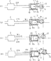
図48は本発明の実施例18による密閉型圧縮機を示す平面断面図である。図49は図48のB−B線における正面断面図である。図50は実施例18の密閉型圧縮機の高負荷運転時における吸入流路の要部断面図を示す。図51は実施例18の密閉型圧縮機の通常運転時における吸入流路の要部断面図を示す。
なお、実施例18の密閉型圧縮機において、前述の各実施例の密閉型圧縮機と同じ機能、構成を有するものには同じ符号を付して、その説明は省略する。
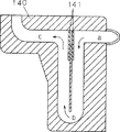
図48及び図49において、吸入流路を有する吸入流路ブロック140は、その吸入流路の一端が密閉容器2内の空間に開口端部として配置されており、他端がバルブプレート150の吸入孔150aにほぼ直結されている。
図50及び図51は吸入流路ブロック140の要部を示す断面図である。吸入流路ブロック140内には流路切り換え機構141が配設されている。流路切り換え機構141は設定温度を境にして、吸入流路を切り換えるよう機能を有し、バイメタル、形状記憶合金あるいは高負荷状態を検知して流路を切り換える弁等により構成されている。
次に、上記のように構成された実施例18の密閉型圧縮機について、その動作を説明する。
一般に低外気温時では、冷凍冷蔵装置は大きな冷凍能力を必要としない。しかし、このような状況において、密閉型圧縮機により必要以上の冷媒循環量が供給されると、吸入圧力の低下、吐出圧力の上昇が起こる。このため、密閉型圧縮機を含む冷凍システム全体の効率が低下し、結果的に総消費電力量が増加するという問題がある。
この問題を解決するために、低外気温時には、冷媒循環量を少なくすることにより、消費電力量は少なくすることができる。
実施例18の密閉型圧縮機は、高外気温時や高負荷時には各部温度が全体に高くなり、吸入流路を有する吸入流路ブロック140内に設けられている流路切り換え機構141の温度も高くなる。その場合、バイメタル、形状記憶合金あるいは高負荷状態を検知して流路を切り換える弁等の流路切り換え機構141は、図50に示される形状に配置されている。この時の吸入される冷媒ガスの流れは、図50におけるa→b→cの方向であり、吸入行程時に吸入孔150a付近で発生する圧力波は冷媒ガスの流れと逆方向に伝播する。そして、圧力波は密閉容器2内の空間で位相の反転した反射波となり冷媒ガスの流れと順方向に伝播し、吸入孔150aに戻ってくる。
吸入行程の間にこの反射波を吸入孔150aへ到達させることにより、吸入完了時点で反射波の持つ圧力エネルギーが冷媒ガスに付加され、冷媒ガスの吸入圧力が上昇する。
そのため、実施例18の密閉型圧縮機は、シリンダー10内にはより密度の高い冷媒ガスが充填されることになる。その結果、圧縮1行程当たりの吐出冷媒量が増加し、冷媒循環量が増加する。このため、実施例18の密閉型圧縮機は、大きな冷凍能力を必要とする高外気温時や高負荷時には従来の密閉型圧縮機と同様に冷凍能力を大幅に向上させることができる。
一方、通常運転時や低外気温時には各部温度が全体に低くなり、流路切り換え機構141の温度も低くなる。その場合、流路切り換え機構141が図51に示すように変形するため、吸入される冷媒ガスは図51に示すa→cの方向に流れる。このため、図51に示す冷媒ガスの流れは、図50に示したa→b→cの方向の流れに比べて短くなり、図51の吸入流路の長さでは、反射波が吸入孔150aに戻るタイミングが早くなり過ぎて、吸入完了時点では反射波の持つ圧力エネルギーが冷媒ガスに付加されず、過給効果は得られないことになる。
逆に吸入流路ブロック140の吸入流路の長さが長い場合には、反射波が吸入孔150aに戻るタイミングが遅くなり過ぎて、吸入完了時点では反射波の持つ圧力エネルギーが冷媒ガスに付加されず、過給効果は得られないことになる。
このように、本発明の実施例18の密閉型圧縮機は、高外気温時や高負荷時にのみ過給効果が得られるように吸入流路の長さ等が調整されている。このため、本発明の実施例18の密閉型圧縮機は、高外気温時や高負荷時以外は必要以上の冷凍能力が発生しなくなり、総合的に消費電力量を少なくすることができる。
以上のように、実施例18の密閉型圧縮機は、密閉容器2と、密閉容器2内に収納され圧縮要素300及び電動機により構成される電動圧縮要素81と、圧縮要素300を構成するシリンダー10と、吸入孔150aを有しシリンダー10の端面に配設されたバルブプレート150と、一端が密閉容器2内に開口し他端がバルブプレート150の吸入孔150aにほぼ直結する吸入流路を有する吸入流路ブロック140と、吸入流路に備えられた流路切り換え機構141とを具備している。このため、実施例18の密閉型圧縮機は、電動圧縮要素81に高負荷がかかる高外気温時や高負荷時にのみ過給効果が得られるようにすることで総合的に消費電力量を少なくすることができる。
なお、実施例18において、吸入流路がバルブプレート150の吸入孔150aにほぼ直結した構成で示したが、わずかな空間を介して吸入流路とバルブプレート150の吸入孔150aとを連結しても上記実施例18と同等の効果が得られる。
実施例18において、吸入流路を図48から図51に示すような吸入流路ブロック140内に形成したもので説明した。しかし、例えば吸入流路を管により構成したものでも上記実施例18と同等の効果が得られる。
《実施例19》
次に、本発明の密閉型圧縮機の一例である実施例19について添付の図を用いて説明する。
図52は本発明の実施例19による密閉型圧縮機を示す平面断面図である。図53は図52のC−C線における正面断面図である。図54は実施例19の密閉型圧縮機の高負荷運転時における吸入流路の要部断面図を示す。図55は実施例19の密閉型圧縮機の通常運転時における吸入流路の要部断面図を示す。
なお、実施例19の密閉型圧縮機において、前述の各実施例の密閉型圧縮機と同じ機能、構成を有するものには同じ符号を付して、その説明は省略する。
図52及び図53において、吸入流路を有する吸入流路ブロック170は、吸入流路の一端が密閉容器2内の空間に開口端部170aとして配置されており、他端がバルブプレート150の吸入孔150aにほぼ直結されている。吸入パイプ161は冷媒ガスを密閉容器2内に導入するものであり、吸入パイプ161の密閉容器内の開口端部は吸入流路ブロック170の開口端部170a近傍に配置されている。
図54及び図55は吸入流路ブロック170の吸入流路の要部を示す断面図であり、吸入流路内には流路切り換え機構171が配設されている。流路切り換え機構171は設定温度を境にして、吸入流路を切り換えるよう機能を有し、バイメタル、形状記憶合金あるいは高負荷状態を検知して流路を切り換える弁等により構成されている。
次に、上記のように構成された実施例19の密閉型圧縮機について、その動作を説明する。
一般に低外気温時では、冷凍冷蔵装置は大きな冷凍能力を必要としない。しかし、このような状況において密閉型圧縮機により必要以上の冷媒循環量が供給されると、吸入圧力の低下、吐出圧力の上昇が起こる。この結果、密閉型圧縮機を含む冷凍システム全体の効率が低下し、結果的に総消費電力量が増加するという問題がある。
この問題を解決するために、低外気温時には、冷媒循環量を少なくすることにより、消費電力量は少なくすることができる。
実施例19の密閉型圧縮機は、高外気温時や高負荷時には各部温度が全体に高くなり、吸入流路ブロック170の吸入流路内に設けられている流路切り換え機構171の温度も高くなる。その場合、バイメタル、形状記憶合金あるいは高負荷状態を検知して流路を切り換える弁等の流路切り換え機構171は、図54に示される形状に配置されている。この時の吸入される冷媒ガスの流れは、図54におけるd→e→fの方向であり、吸入行程時に吸入孔150a付近で発生する圧力波は冷媒ガスの流れと逆方向に伝播する。その圧力波は、密閉容器2内の空間で位相の反転した反射波となり、冷媒ガスの流れと順方向に伝播し、吸入孔150aに戻ってくる。
吸入行程の間にこの反射波を吸入孔150aへ到達させることにより、吸入完了時点で反射波の持つ圧力エネルギーが冷媒ガスに付加され、冷媒ガスの吸入圧力が上昇する。
そのため、実施例19の密閉型圧縮機は、シリンダー10内にはより密度の高い冷媒ガスが充填されることになり、圧縮1行程当たりの吐出冷媒量が増加し、冷媒循環量が増加する。このため、実施例19の密閉型圧縮機は、大きな冷凍能力を必要とする高外気温時や高負荷時には従来の密閉型圧縮機と同様に冷凍能力を大幅に向上させることができる。
一方、通常運転時や低外気温時には各部温度が全体に低くなり、流路切り換え機構171の温度も低くなる。その場合、流路切り換え機構171が図55に示すように変形するため、吸入される冷媒ガスは図55に示すようにd→fの方向に流れる。このため、図55に示す冷媒ガスの流れは、図54に示したd→e→fの方向の流れに比べて短くなる。このため、図55に示す吸入流路の長さでは、反射波が吸入孔150aに戻るタイミングが早くなり過ぎて、吸入完了時点では反射波の持つ圧力エネルギーが冷媒ガスに付加されず、過給効果は得られないことになる。
逆に吸入流路ブロック170の吸入流路の長さが長い場合には、反射波が吸入孔150aに戻るタイミングが遅くなり過ぎて、吸入完了時点では反射波の持つ圧力エネルギーが冷媒ガスに付加されず、過給効果は得られないことになる。
このように、本発明の実施例19の密閉型圧縮機は、高外気温時や高負荷時のみ過給効果が得られるように吸入流路の長さ等が調整されている。このため、本発明の実施例19の密閉型圧縮機は、高外気温時や高負荷時以外は必要以上の冷凍能力が発生しなくなり、総合的に消費電力量を少なくすることができる。
本発明の実施例19の密閉型圧縮機は、吸入流路ブロック170における吸入流路の密閉容器2内の開口端部171aを吸入パイプ161の密閉容器2内の開口端部の近傍に設けている。これにより、実施例19の密閉型圧縮機は、吸入流路ブロック170の吸入流路に吸入される冷媒ガスが密閉容器2内の圧縮発熱、電動機発熱、摺動発熱等の影響で高温となっている電動圧縮要素81から受ける熱の影響を少なくすることができ、温度上昇を少なくすることができる。
従って、実施例19の密閉型圧縮機は、吸入流路内の冷媒ガスの密度を高め、冷媒循環量を増加させることができ、効率を高くすることができる。
以上のように、実施例19の密閉型圧縮機は、密閉容器2と、密閉容器2内に収納され圧縮要素300及び電動機等のモータ部7により構成される電動圧縮要素81と、圧縮要素300を構成するシリンダー10と、吸入孔150aを有しシリンダー10の端面に配設されたバルブプレート150と、一端が密閉容器2外に連通し他端が密閉容器2内に開口した吸入パイプ161と、一端が吸入パイプ161の密閉容器2内の開口端部の近傍に開口し、他端がバルブプレート150の吸入孔150aにほぼ直結する吸入流路と、吸入流路に備えられた流路切り換え機構171とを具備している。
このため、実施例19の密閉型圧縮機は、電動圧縮要素81に高負荷がかかる高外気温時や高負荷時にのみ過給効果が得られるように構成されている。実施例19の密閉型圧縮機は、総合的に消費電力量を少なくすることができる。
実施例19の密閉型圧縮機は、吸入される冷媒ガスの温度上昇を小さくすることにより、冷媒ガスの密度を高め、冷媒循環量を増加させることにより効率を高くすることができる。
なお、実施例19において、吸入流路がバルブプレート150の吸入孔150aにほぼ直結した構成とした。しかし、わずかな空間(実質的に同じ断面形状を有する流路空間)を介して吸入流路とバルブプレート150の吸入孔150aとを連結する構成であっても上記実施例19とほぼ同等の効果が得られる。
実施例19において、吸入流路を図52から図55に示すように吸入流路ブロックに吸入流路を形成したもので説明したが、例えば吸入流路を管により構成したものでも上記実施例19と同等の効果が得られる。
《実施例20》
次に、本発明の密閉型圧縮機の一例である実施例20について添付の図を用いて説明する。
図56は本発明の実施例20による密閉型圧縮機を示す平面断面図である。図57は実施例20の密閉型圧縮機の概略構造と冷凍装置の制御ブロック図である。図58はインバータ装置を用いて実施例20の密閉型圧縮機の回転数制御時の冷凍能力変化を示す特性図である。
なお、実施例20の密閉型圧縮機において、前述の各実施例の密閉型圧縮機と同じ機能、構成を有するものには同じ符号を付して、その説明は省略する。
図56及び図57において、第1の吸入パイプ193はその一端が密閉容器2内の空間に開口し、他端がバルブプレート150の吸入孔150aにほぼ直結された吸入流路としての吸入管である。図57に示すインバータ装置212は、電動機211を少なくとも2種類以上の特定周波数で運転する。
次に、上記のように構成された実施例20の密閉型圧縮機について、その動作を説明する。
一般に低外気温時では、冷凍冷蔵装置は大きな冷凍能力を必要としない。しかし、このような状況において、従来の密閉型圧縮機により必要以上の冷媒循環量が供給されると、吸入圧力の低下、吐出圧力の上昇が起こる。この結果、従来の密閉型圧縮機を含む冷凍システム全体の効率が低下し、結果的に総消費電力量が増加するという問題がある。
この問題を解決するために、低外気温時には、冷媒循環量を少なくすることにより、消費電力量は少なくすることができる。
実施例20の密閉型圧縮機は、吸入行程時に吸入孔150a付近で発生した圧力波は、冷媒ガスの流れと逆方向に伝播する。そして、圧力波は、密閉容器2内の空間で位相の反転した反射波となり、冷媒ガスの流れと順方向に伝播し、吸入孔150aに戻ってくる。
吸入行程の間にこの反射波を吸入孔150aへ到達させることにより、吸入完了時点で反射波の持つ圧力エネルギーが冷媒ガスに付加され、冷媒ガスの吸入圧力が上昇する。
そのため、実施例20の密閉型圧縮機は、シリンダー10内に、より密度の高い冷媒ガスが充填されることになる。このため、実施例20の密閉型圧縮機は、圧縮1行程当たりの吐出冷媒量が増加し、冷媒循環量が増加する。このような過給効果により、実施例20の密閉型圧縮機は、冷凍能力を大幅に向上させることができる。
次に、図58を用いて過給効果について具体例について説明する。図58はインバータ装置を用いて密閉型圧縮機を回転数制御したときの冷凍能力変化を示す特性図である。図58において、横軸は回転数(r/s)を示し、縦軸は冷凍能力相対値を示す。冷凍能力相対値は従来の密閉型圧縮機の回転数が60Hzのときを基準としている。図58において、実線は従来の密閉型圧縮機を回転数制御した場合である。破線▲1▼と破線▲2▼は実施例20における気筒容積の異なる密閉型圧縮機をそれぞれ回転数制御した場合である。なお、図58において1点鎖線は回転数の増加とともに冷凍能力も比例して増加する場合を示す。
回転数制御を行う従来の往復型の密閉型圧縮機を用いて、周波数60Hzの運転時に過給効果が得られるように構成した場合、冷凍能力変化は図11の破線▲1▼のように変化する。
図11の実線に示すように、従来の密閉型圧縮機では回転数が50Hzを越える高速回転数時において、回転数の増加に比例した冷凍能力がバルブ機構の追従性等の問題で得られず、冷凍能力が飽和し、更に低下するという特性を有していた。
しかし、実施例20の密閉型圧縮機によると、過給により高速側の回転数である60Hzの近傍で冷凍能力が従来の装置に比べて大幅に向上しており、同じ60Hz運転において約2割の能力上昇が見られた。図58の破線▲1▼に示すように、実施例20の密閉型圧縮機は回転数の増加に比例して冷凍能力が得られると想定した場合における70Hz運転のときと同等の冷凍能力を確保できた。
また、図58に示すように、60Hz運転時における従来の装置と同じ冷凍能力は、破線▲2▼で示す約2割小さい気筒容積の実施例20の密閉型圧縮機により得られた。
このように、実施例20の密閉型圧縮機によれば、冷凍能力の範囲を広くすることができ、外気温や負荷に応じた冷凍能力が得られるように構成できる。更に、図58の破線▲2▼で示すように、従来より小さい気筒容積の密閉型圧縮機により、従来のものとほぼ同等の冷凍能力が得られるように構成でき、密閉型圧縮機の小型化が達成できる。
これにより、実施例20の密閉型圧縮機によると、回転数制御に加えて過給を行うことにより、外気温や負荷に応じた冷凍能力が得られ、消費電力量を少なくすることができる。
以上のように、実施例20の密閉型圧縮機は、密閉容器2と、密閉容器2内に収納され圧縮要素300及び電動機211により構成される電動圧縮要素81と、圧縮要素300を構成するシリンダー10と、吸入孔150aを有するバルブプレート150と、一端が密閉容器1内あるいはアキュムレータ等の空間に開口し他端が吸入孔150aに実質的に直結する第1の吸入パイプ193と、電動機211を運転するインバータ装置212とから構成されている。このため、実施例20の密閉型圧縮機は、外気温や負荷に応じた冷凍能力が得られ、消費電力量を少なくすることができる。
なお、実施例20の密閉型圧縮機は、ロータリ型や、スクロール型圧縮機などでも上記実施例20と同様の効果が得られることは言うまでもない。
実施例20において、吸入流路として吸入パイプを用いて構成したが、吸入流路を有するブロック状のもので構成したものでも上記実施例20と同等の効果が得られる。
《実施例21》
次に、本発明の密閉型圧縮機の一例である実施例21について添付の図を用いて説明する。
図59は本発明の実施例21による密閉型圧縮機の平面断面図である。図60は図59のB−B線における正面断面図である。図61は実施例21の密閉型圧縮機の吸入流路付近を示す断面図である。
なお、実施例21の密閉型圧縮機において、前述の各実施例の密閉型圧縮機と同じ機能、構成を有するものには同じ符号を付して、その説明は省略する。
図59、図60及び図61において、吸入ブロック227に形成された吸入流路222は一端が開口端部として密閉容器2内の空間に配置され、他端がバルブプレート192の吸入孔192aに実質的に直結されている。図61に示すように、吸入流路222とともに吸入ブロック227内に形成されている共鳴型マフラー232は、空胴部242と結合部252とを有している。共鳴型マフラー232の結合部252は、その一端が空胴部242に開口し、他端が吸入流路222に開口している。共鳴型マフラー232の共振周波数は、吸入される冷媒ガスの脈動等により吸入孔192a付近で発生する騒音のうち最も問題となる騒音の周波数と一致するように、空胴部242の容積、結合部252の長さ、結合部252の断面積等が調整されている。
次に、上記のように構成された実施例21の密閉型圧縮機について、その動作を説明する。
冷媒ガスがシリンダー10内に吸入されると、冷媒ガスの脈動やサクションリードの動作により吸入孔192a付近で騒音が発生する。この発生した騒音は吸入流路222を伝達する際、吸入流路222に設けられた共鳴型マフラー232によって減衰される。そのため、吸入流路222から密閉容器2内の空間に伝達する騒音は小さくなり、密閉型圧縮機から生じる騒音を小さくすることができる。
次に、実施例21における共鳴型マフラー232が冷凍能力を向上させる効果、すなわち過給効果に与える影響について説明する。
前述の背景技術において説明した従来の密閉型圧縮機において、吸入流路からの騒音で最も問題となる周波数は通常400Hzから600Hz程度である。それに対し、吸入行程時に発生して過給効果を与える圧力波の周波数はかなり小さい。また、共鳴型のマフラーは、一般に共振周波数付近の狭い周波数帯域だけの消音効果が大きいという特徴がある。
従って、上記実施例21において、吸入行程時に発生した圧力波(膨張波)が反射波(圧縮波)となり、吸入孔192aに戻ってくる過程において、共鳴型マフラー232は問題となる騒音だけを減衰させて、過給効果を与える圧力波に対してはほとんど影響を与えないため、大きな冷凍能力は共鳴型マフラー232が設置されていないものと同じように得られる。
このように、過給効果を与える仕様の密閉型圧縮機においては、吸入流路222に共鳴型マフラー232を設ける構成は非常に有効であり、過給効果と騒音低減を両立することができる。
以上のように、本実施例21の密閉型圧縮機は、一端が密閉容器2内の空間に開口し、他端が吸入孔192aにほぼ直結する吸入流路222と、吸入流路222に設けられた共鳴型マフラー232とから構成されている。このため、大きな冷凍能力は従来通り得られ、さらに吸入された冷媒ガスの脈動に伴い発生する騒音は吸入流路222に設けた共鳴型マフラー232により減衰され、吸入流路222から密閉容器2内に伝達する騒音は小さくなる。
このため、実施例21の密閉型圧縮機は、最終的に密閉容器外に伝達する騒音を小さくすることができる。
なお、実施例21において、共鳴型マフラー232は空胴部242と結合部252とを有する構成にしたが、空胴部が吸入流路222に直接接続した形状のもの、いわゆるサイドブランチ形や、その他の形状であっても共鳴型マフラー形状であれば、上記実施例21と同様の効果が得られる。
《実施例22》
次に、本発明の密閉型圧縮機の一例である実施例22について添付の図を用いて説明する。
図62は本発明の実施例22による密閉型圧縮機のシリンダー付近を示す断面図である。
なお、実施例22の密閉型圧縮機において、前述の各実施例の密閉型圧縮機と同じ機能、構成を有するものには同じ符号を付して、その説明は省略する。
図62において、吸入孔273を有するバルブプレート263はシリンダー10の端面に固着されている。吸入流路283はその一端が開口端部として密閉容器2内の空間に配置されている、他端が前記吸入孔273に実質的に直結している。
バルブプレート263にはサクションリード293が取り付けられており、吸入孔273の開閉を行っている。
図62に示すように、吸入孔273に対する吸入流路283の接続部分における流路の軸方向は、バルブプレート263の端面に対して直角とならないように傾斜して構成されている。
次に、上記のように構成された実施例22の密閉型圧縮機について、その動作を説明する。
まず、背景技術において説明した図71に示した従来の密閉型圧縮機の場合について説明する。図71において、吸入行程時に発生した圧力波(膨張波)は、密閉容器2内の空間で位相の反転した反射波Wb(圧縮波)となり、吸入孔19aに戻ってくる。しかし、図71に示すように、反射波Wbの進む方向に対してサクションリード20の開閉面は垂直に近い角度であるため、反射波Wbの多くはサクションリード20においてほぼ反対の方向に反射される。このため、従来の密閉型圧縮機においては、シリンダー10内に反射波Wbの圧力エネルギーが有効に働かず、過給効果が十分に得られないという問題があった。
それに対し、図62に示す本発明の実施例22の密閉型圧縮機は、吸入流路273がバルブプレート263の端面に対して垂直ではなく傾斜して接続している。このため、図62に示すように、反射波Wcはサクションリード293において反射されることなく直接シリンダー10内に入る。また、反射波Wdは、サクションリード293に反射される場合でも、反射波Wdの進む方向とサクションリード293の開閉面との角度が小さいため、図62に示すように、反射後の反射波Wdの進む向きは大きく変わらず、シリンダー10内に入りやすくなる。
以上のように、実施例22の密閉型圧縮機においては、反射波がサクションリード293によって妨害されにくい構成であるため、シリンダー10内に反射波の圧力エネルギーが有効に入るようになり、実施例22の密閉型圧縮機は大きな冷凍能力を有する。
吸入される冷媒ガスの進む方向とサクションリード293の開閉面とのなす角度は小さいため、サクションリード293による冷媒ガスの流れの抵抗も小さくなり、圧力損失が減少する。このため、さらに実施例22の密閉型圧縮機は優れた冷凍効率を有し、高い冷凍能力を有する。
以上のように、実施例22の密閉型圧縮機は、吸入孔273への吸入流路283の接続部分の流路の軸方向がバルブプレート263の端面に対して垂直とならないように傾斜して構成されている。このため、実施例22の密閉型圧縮機は、反射波がシリンダー10内に戻るとき、反射波はサクションリード293に反射されずに直接シリンダー10内に入りやすい構成である。また、反射波がサクションリード293に反射される場合でも、反射波の進む方向とサクションリード293の開閉面とのなす角度は小さくなる。このため、反射後の反射波の進む向きは大きく変わらず、反射波はシリンダー10内に入りやすくなる。すなわち、反射波はサクションリード293によって妨害されにくくなり、シリンダー10内に反射波の圧力エネルギーが有効に入るようになる。このため、実施例22の密閉型圧縮機は優れた冷凍効率を有し、高い冷凍能力を有する。
サクションリード293による吸入された冷媒ガスの流れの抵抗が小さく、圧力損失が小さい。このため、実施例22の密閉型圧縮機はさらに高い冷凍能力を有する。
《実施例23》
次に、本発明の密閉型圧縮機の一例である実施例23について添付の図を用いて説明する。
図63は本発明の実施例23による密閉型圧縮機の低外気温時の停止時におけるシリンダー付近を示す断面図である。図64は本発明の実施例23による密閉型圧縮機の高外気温時の停止時におけるシリンダー付近を示す断面図である。
なお、実施例23の密閉型圧縮機において、前述の各実施例の密閉型圧縮機と同じ機能、構成を有するものには同じ符号を付して、その説明は省略する。
図63及び図64において、シリンダー10の端面とバルブプレート194との間にサクションリード304が設けられている。このサクションリード304はバルブプレート194の吸入孔194aの開閉を行うよう構成されている。サクションリード304にはサクションリード304の初期たわみ量を制御するたわみ制御機構314が取り付けられている。実施例23において、たわみ制御機構314は、サクションリード304より線膨張係数の小さい材料により形成されており、サクションリード304のピストン側に固定されている。
次に、上記のように構成された実施例23の密閉型圧縮機について、その動作を説明する。
一般に低外気温時では、冷凍冷蔵装置は大きな冷凍能力を必要としない。しかし、このような状況において従来の密閉型圧縮機により必要以上の冷媒循環量が供給されると、吸入圧力の低下、吐出圧力の上昇が起こる。この結果、従来の密閉型圧縮機を含む冷凍システム全体の効率が低下し、結果的に総消費電力量が増加するという問題がある。
この問題を解決するために、低外気温時には、冷媒循環量を少なくすることにより、消費電力量は少なくすることができる。
実施例23の密閉型圧縮機は、低外気温時には各部温度も全体に低くなり、サクションリード304とたわみ制御機構314の温度も低くなっている。その場合、停止時におけるサクションリード304は、図63に示すように、吸入孔194aを閉じる状態、すなわちサクションリード304の初期たわみが0の状態となっている。この状態においては、吸入孔194が開いてから閉じるまでの時間は、初期たわみがある場合に比べて短くなるとともに、サクションリード304の変位量も小さくなる。そのため、吸入行程時に発生した圧力波が反射波となって吸入孔194に戻ってきたとき、シリンダー10内に吸入される冷媒ガスの量はやや少なくなり、過給による冷媒循環量の向上効果は小さくなる。従って、実施例23の密閉型圧縮機は、低外気温時においては消費電力量を小さく抑えることができる。
高外気温時ではサクションリード304とたわみ制御機構314の温度も高くなり、サクションリード304よりたわみ制御機構314の方が線膨張係数が小さいため、温度上昇による材料の膨張率に差が生じてバイメタルの様に働く。その結果、停止時におけるサクションリード304は、図64に示すように、吸入孔194aを開ける状態、すなわちサクションリード304の初期たわみがある状態となっている。この状態においては、吸入孔194aが開いてから閉じるまでの時間は、初期たわみが0の場合に比べて長くなるとともに、サクションリード304の変位量も大きくなる。そのため、吸入行程時に発生した圧力波が反射波となって吸入孔194aに戻ってきたとき、シリンダー10内に吸入される冷媒ガスの量は多くなり、過給による冷媒循環量の向上効果は十分に得られる。従って、実施例23の密閉型圧縮機は、大きな冷凍能力が必要となる高外気温時に、過給効果による十分な冷凍能力の向上効果が得られる。
以上のように、実施例23の密閉型圧縮機は、サクションリード304の初期たわみ量を制御するたわみ制御機構314がサクションリード304より線膨張係数の小さい材料により形成され、サクションリード304のピストン側に固定されている。このため、実施例23の密閉型圧縮機は、大きな冷凍能力を必要としない低外気温時には冷凍能力の向上効果が小さくなって消費電力量を小さく抑え、一方大きな冷凍能力を必要とする高外気温時には十分な冷凍能力向上効果が得られるように構成している。このため、実施例23の密閉型圧縮機においては、冷凍能力制御をすることにより総消費電力量を小さくすることができる。
なお、実施例23において、たわみ制御機構314はサクションリード304より線膨張係数の小さい材料により形成し、サクションリード304のピストン側に固定するように構成した。しかし、たわみ制御機構314はサクションリード304より線膨張係数の大きい材料で、サクションリード304の反ピストン側に固定しても、上記実施例23と同様の効果が得られる。
《実施例24》
次に、本発明の密閉型圧縮機の一例である実施例24について添付の図を用いて説明する。
図65は本発明の実施例24による密閉型圧縮機の低外気温時の停止時におけるシリンダー付近を示す断面図である。図66は本発明の実施例24による密閉型圧縮機の高外気温時の停止時におけるシリンダー付近を示す断面図である。
なお、実施例24の密閉型圧縮機において、前述の各実施例の密閉型圧縮機と同じ機能、構成を有するものには同じ符号を付して、その説明は省略する。
図65及び図66において、シリンダー10の端面とバルブプレート195との間にサクションリード325が設けられている。サクションリード325はバルブプレート195の吸入孔195aの開閉を行うよう構成されている。実施例24にはサクションリード325の初期たわみ量を制御するたわみ制御機構345が取り付けられている。たわみ制御機構345はバイメタルあるいは形状記憶合金等の温度によって変形する材料により構成されており、バルブプレート195に形成された貫通孔195b内に配置されている。たわみ制御機構345は貫通孔195b内において伸縮自在に備え付けられている。
次に、上記のように構成された実施例24の密閉型圧縮機について、その動作を説明する。
一般に低外気温時では、冷凍冷蔵装置は大きな冷凍能力を必要としない。しかし、このような状況において従来の密閉型圧縮機により必要以上の冷媒循環量が供給されると、吸入圧力の低下、吐出圧力の上昇が起こる。その結果、従来の密閉型圧縮機を含む冷凍システム全体の効率が低下し、結果的に総消費電力量が増加するという問題がある。
この問題を解決するために、低外気温時には、冷媒循環量を少なくすることにより、消費電力量は少なくすることができる。
実施例24の密閉型圧縮機は、低外気温時には各部温度も全体に低くなり、たわみ制御機構345の温度も低くなっている。その場合、たわみ制御機構345はサクションリード325を押し上げることがなく、停止時におけるサクションリード325は、図65に示すように、吸入孔195aを閉じる状態、すなわちサクションリード325の初期たわみが0の状態となっている。この状態においては、吸入孔195aが開いてから閉じるまでの時間は、初期たわみがある場合に比べて短くなる。そのため、吸入行程時に発生した圧力波が反射波となって吸入孔195aに戻ってきたとき、シリンダー10内に吸入される冷媒ガスの量はやや少なくなり、過給による冷媒循環量の向上効果は小さくなる。従って、実施例24の密閉型圧縮機は、低外気温時においては消費電力量を小さく抑えることができる。
一方、高外気温時ではたわみ制御機構345の温度も高くなり、たわみ制御機構345は伸びて、サクションリード325を押し上げる。このため、停止時におけるサクションリード325は、図66に示すように、吸入孔195aを開ける状態、すなわちサクションリード325の初期たわみがある状態となっている。この状態における吸入孔195aが開いてから閉じるまでの時間は、初期たわみが0の場合に比べて長くなる。そのため、吸入行程時に発生した圧力波が反射波となって吸入孔195aに戻ってきたとき、シリンダー10内に吸入される冷媒ガスの量は多くなり、過給による冷媒循環量の向上効果は十分に得られる。
従って、実施例24の密閉型圧縮機は、大きな冷凍能力が必要となる高外気温時には、過給効果による十分な冷凍能力の向上効果が得られる。
以上のように、実施例24の密閉型圧縮機は、サクションリード325の初期たわみ量を制御するたわみ制御機構345がバイメタルあるいは形状記憶合金等の温度によって変形する材料により構成されており、バルブプレート195内に伸縮自在に備え付けられた構成となっている。このため、実施例24の密閉型圧縮機では、大きな冷凍能力を必要としない低外気温時には冷凍能力の向上効果が小さくなって消費電力量を小さく抑え、大きな冷凍能力を必要とする高外気温時には十分な冷凍能力向上効果が得られる。従って、実施例24の密閉型圧縮機は、冷凍能力制御をすることにより、総消費電力量を小さくすることができる。
産業上の利用可能性
本発明の密閉型圧縮機は、冷凍冷蔵装置等に使用されるものであり、冷媒ガスの吸入が完了する時点でのシリンダー内の圧力を冷凍サイクルの低圧側圧力よりも高めることにより、シリンダー内に吸い込まれる冷媒ガスの密度を高めて、高い冷凍能力を発揮するものであり、かつ、圧縮動作の吸入時に発生する共鳴音の発生を防止して、騒音の発生を抑制した静かな冷凍冷蔵装置等を構成するために用いられる。Technical field
The present invention relates to a hermetic compressor used in a freezer / refrigerator and the like.
Background art
A hermetic compressor used in a refrigeration apparatus or the like is strongly desired to improve refrigeration capacity and to reduce noise.
As a conventional technique for improving the refrigerating capacity, for example, there is a hermetic compressor disclosed in Japanese Patent Application Laid-Open No. 57-122192 and Japanese Patent Application Laid-Open No. 6-50262. In these conventional technologies, the pressure in the cylinder at the time when the suction of the refrigerant gas is completed is higher than the low-pressure side pressure of the refrigeration cycle, thereby increasing the density of the refrigerant gas sucked into the cylinder and further improving the refrigeration capacity I am trying.
Moreover, as a prior art aiming at noise reduction, for example, there is a hermetic compressor disclosed in JP-A-6-74154. In this hermetic compressor, the suction part for sucking refrigerant gas into the cylinder is improved in order to prevent the generation of resonance noise in the hermetic container that occurs during suction in the compression operation stroke.
Hereinafter, an example of a conventional hermetic compressor that reduces noise will be described with reference to the drawings.
67 is a longitudinal sectional view showing a conventional hermetic compressor, and FIG. 68 is a plan sectional view showing the conventional hermetic compressor of FIG.
67 and 68, the
The
68 indicates the minimum distance between the inner wall surfaces of the
The
The operation of the conventional hermetic compressor configured as described above will be described below.
Refrigerant gas circulated from a system such as a refrigerator / freezer is once opened into the space inside the sealed
Since the refrigerant gas is not continuously sucked into the
However, the reciprocation of the
Therefore, in the conventional hermetic compressor shown in FIGS. 67 and 68, the pressure pulsation vibrates the node in the resonance mode. For this reason, in the conventional hermetic compressor, the resonance mode is not excited, the generation of the resonance is prevented, and the noise due to the resonance is suppressed.
When the resonance mode of the resonance frequency in question is in the reciprocating direction of the
Further, when the resonance mode of the resonance frequency in question is in the axial direction of the
Next, an example of a conventional hermetic compressor for improving the refrigerating capacity will be described with reference to the drawings.
FIG. 69 is a longitudinal sectional view showing a conventional hermetic compressor for improving the refrigerating capacity. 70 is a plan sectional view of the conventional hermetic compressor shown in FIG. 71 is a main-portion cross-sectional view taken along the line AA in FIG. FIG. 72 is an explanatory diagram of refrigerant gas behavior.
In FIGS. 69, 70, 71 and 72, the
On the other hand, in the conventional rotary compressor for improving the refrigerating capacity disclosed in Japanese Patent Laid-Open No. 57-122192, the length L (m) of the
(T × a / 4-0.2) ± 0.1 = L
It becomes.
Next, the operation of the conventional hermetic compressor configured as described above will be described.
In FIG. 72, the refrigerant gas is closed at the
Next, the
The pressure wave Wa that has reached the space in the sealed
That is, the pressure wave Wa generated in the
By matching the time when the reflected wave Wb reaches the
As a result, the
However, in the configuration of the conventional hermetic compressor described above, resonance occurs when the temperature of the refrigerant gas changes due to a change in the outside air temperature and the speed of sound transmitted through the refrigerant gas (hereinafter referred to as the speed of sound in the refrigerant gas) changes. There is a possibility that the position of the node of the resonance mode of the frequency changes, and the generation of the resonance sound cannot be suppressed.
In addition, there is a possibility that a noise is generated due to an impact sound generated by a pressure wave generated by the suction pipe.
When the temperature of the refrigerant gas changes due to a change in the outside air temperature, and the sound speed in the refrigerant gas changes, the wavelength of the pressure wave or the reflected wave changes depending on the sound speed. For this reason, an error occurs in the timing of adding the pressure energy of the reflected wave when the suction is completed, and the rate of increase of the suction pressure is reduced.
For this reason, it is difficult to fill the cylinder with a high-density refrigerant gas, and the amount of refrigerant gas discharged per compression stroke is reduced, which may reduce the refrigerating capacity.
In addition, a method of constantly increasing the refrigerant gas circulation amount to improve the refrigerating capacity regardless of changes in the outside air temperature is also conceivable. In this case, however, the room is often closed in the winter when the outside air temperature is low, and there is a possibility that the noise caused by the impact sound is more worrisome than in the summer.
The present invention solves the above-described problems, and an object of the present invention is to provide a hermetic compressor having a high refrigeration capacity, a small refrigerant gas suction loss, and a high refrigeration efficiency. .
Therefore, the hermetic compressor of the present invention achieves the above-described object and the following technical advantages in various embodiments to be described later.
In Example 1 described later of the present invention, even if the sound speed in the refrigerant gas changes due to the temperature change of the refrigerant gas, and the node of the resonance mode of the resonance frequency changes, the opening end of the suction pipe is always in the resonance mode. Adjust so that it becomes a node. Thus, a hermetic compressor that suppresses the generation of resonance noise and achieves low noise is provided.
In the second embodiment of the present invention, which will be described later, the opening end of the suction pipe is made to be a node in the resonance mode, thereby greatly reducing the generation of impact noise caused by the pressure wave of the suction pipe. In this way, it is possible to provide a highly efficient hermetic compressor that reduces noise, increases refrigeration capacity, and has low refrigerant gas suction loss.
In Example 3 to be described later of the present invention, the length of the suction flow path in the suction pipe is changed. As a result, even when the outside air temperature changes and the sound velocity in the refrigerant gas changes due to the temperature change of the refrigerant gas, the time when the reflected wave reaches the suction hole and the time when the volume in the cylinder becomes maximum (the time when the suction is completed) Can be matched. Therefore, the pressure energy of the reflected wave is added to the refrigerant gas when the suction is completed, and the suction pressure of the refrigerant gas is increased.
As a result, the suction pressure is constantly increased, the amount of refrigerant gas discharged per compression stroke is increased, the amount of refrigerant gas circulated is increased, the refrigeration capacity is improved, and the refrigerant gas suction loss is reduced. Therefore, a highly efficient hermetic compressor is obtained.
In Example 4 to be described later of the present invention, the inner diameter sectional area of the suction pipe is changed. As a result, even when the outside air temperature changes and the sound velocity in the refrigerant gas changes due to the temperature change of the refrigerant gas, the time when the reflected wave reaches the suction hole and the time when the volume in the cylinder becomes maximum (the time when the suction is completed) Can be matched. Therefore, the pressure energy of the reflected wave is added when the suction is completed, and the suction pressure of the refrigerant gas increases.
As a result, the suction pressure always increases, the amount of refrigerant discharged per compression stroke increases, the amount of refrigerant circulation increases, the refrigeration capacity is improved, and the refrigerant gas suction loss is reduced. Therefore, a highly efficient hermetic compressor is obtained.
When the outside air temperature does not require a large improvement in refrigeration capacity compared with the high outside air temperature, the inside cross-sectional area of the suction pipe is reduced, and the inside diameter cross-sectional area of the suction pipe is reduced as the outside air temperature is low. As a result, a hermetic compressor capable of greatly reducing noise can be obtained.
In the conventional configuration, the rotational position of the crankshaft when the reflected wave returns to the suction hole is not necessarily optimal depending on the length of the
Therefore, in Example 5 to be described later of the present invention, the suction pipe length and the like are adjusted so that the rotation position (crank angle) of the crankshaft where the reflected wave returns to the suction hole is optimized, and thereby the maximum A hermetic compressor capable of improving the refrigerating capacity is obtained.
In the conventional configuration, the refrigeration capacity is always improved regardless of whether the outside air temperature is high or low. For this reason, at low outside temperatures that do not require large refrigeration capacity, more refrigeration capacity than necessary is supplied, and the efficiency of the entire refrigeration system including the hermetic compressor tends to decrease, resulting in a large total power consumption. There was a drawback of being.
Therefore, in Example 6 to be described later of the present invention, the effect of improving the refrigeration capacity is not obtained at a low outside temperature that does not require a large refrigeration capacity, and the power consumption is suppressed to a small value, while the large refrigeration capacity is required. When the outside temperature is high, the conventional refrigeration capacity is improved. By performing the refrigerating capacity control in this way, a hermetic compressor with a small total power consumption can be obtained.
In the conventional configuration, when the resonance frequency of the refrigerant gas in the sealed container is close to an integral multiple of the number of rotations of the crankshaft, resonance sound is generated and the refrigerant gas in the sealed container resonates. For this reason, the refrigerant gas in the sealed container resonates when the pressure wave is reflected at the open end of the suction pipe. As a result, the pressure amplitude of the reflected wave is reduced, the rate of increase of the suction pressure is reduced, and the effect of improving the refrigerating capacity tends to be reduced.
Therefore, in Example 7 to be described later of the present invention, the resonance frequency of the refrigerant gas in the sealed container is configured not to be close to an integral multiple of the rotation speed of the crankshaft. As a result, the generation of resonance noise was prevented, and the attenuation of pressure amplitude when the pressure wave was reflected at the opening of the suction pipe was prevented. Accordingly, a hermetic compressor in which the suction pressure is constantly increased and the effect of improving the refrigerating capacity can be obtained.
In Example 8 to be described later of the present invention, the pulsation of the refrigerant gas to be sucked in is reduced to reduce the force for exciting the refrigerant gas in the sealed container, so that it always resonates regardless of the resonance frequency of the refrigerant gas in the sealed container. Reduce the sound. At the same time, the pressure amplitude is prevented from being attenuated when the pressure wave is always reflected at the opening end of the suction pipe regardless of the resonance frequency of the refrigerant gas in the sealed container. Therefore, a suction compressor in which the suction pressure is always increased regardless of any changes in the shape of the sealed container and the operating conditions, and the effect of improving the refrigerating capacity can be obtained.
In the conventional configuration shown in FIG. 69 described above, the
Therefore, in a ninth embodiment to be described later of the present invention, even if the temperature of the cylinder head or the like changes greatly, the temperature change of the suction pipe is reduced. As a result, the change in sound speed in the refrigerant gas can be reduced, and a stable suction pressure increase effect is generated. Therefore, it is possible to obtain a hermetic compressor having a stable and high refrigerating capacity without being affected by the passage of time after starting.
In the conventional configuration shown in FIG. 69, since the open end 21a of the
If the open end 21a of the
In a tenth embodiment of the present invention, which will be described later, a large pressure wave is generated to increase the suction pressure increase effect, and a refrigerant gas having a low temperature is sucked into the cylinder. As a result, the effect of improving the refrigerant circulation rate by the refrigerant gas having a low temperature is added, the effect of improving the refrigerating capacity is greatly increased, and a hermetic compressor with high refrigerating capacity and low noise can be obtained.
In the conventional configuration shown in FIG. 69, when the speed of sound in the refrigerant gas changes due to a change in operating conditions or the like, the length of the
Therefore, in Example 11 to be described later of the present invention, the suction pressure is always increased regardless of changes in the operating conditions, and a stable and high refrigeration capacity is supplied.
In the conventional configuration shown in FIG. 69, since the
Therefore, in a twelfth embodiment of the present invention, a starting failure is prevented by suppressing the effect of increasing the suction pressure during starting and lowering the starting torque. Thus, it is possible to obtain a hermetic compressor having high refrigeration capacity due to the effect of increasing the suction pressure during the stable operation while improving the reliability.
In the conventional configuration shown in FIG. 69, when the refrigerant gas is heated in the space in the sealed
Therefore, in Example 13 to be described later of the present invention, the opening end portion in the hermetic container of the first suction pipe serving as the suction flow path is disposed so as to be the node portion of the resonance mode. Further, the opening end portion in the sealed container of the second suction pipe is provided in the vicinity of the opening end portion of the suction flow path. By these, the resonance which arises in an airtight container is prevented. Therefore, an object of the present invention is to provide a hermetic compressor that is low in noise and increases the density of refrigerant gas to improve the refrigerating capacity.
In the conventional configuration shown in FIG. 69, a shock wave is generated by the pressure wave generated by the
Therefore, in a fourteenth embodiment to be described later of the present invention, the opening end portion in the hermetic container of the first suction pipe serving as the suction flow path is disposed so as to be a resonance mode node. In addition, the opening end in the sealed container of the second suction pipe is provided in the vicinity of the opening end of the suction flow path. For this reason, the generation of the impact sound generated by the pressure wave in the suction flow path is greatly reduced, and a hermetic compressor having a low noise and a high refrigerant gas density and a greatly improved refrigeration capacity can be obtained.
In the conventional configuration, since a long suction channel is provided in a limited closed container, the structure of the suction channel is complicated and has a plurality of bent portions having different curvatures. For this reason, when the pressure wave Wa or the reflected wave Wb propagates through the suction flow path, the pressure amplitude is reduced in the bent portions having different curvatures. Further, when the reflected wave Wb returns to the suction hole of the valve plate, the pressure amplitude of the reflected wave Wb is attenuated, and the conventional hermetic compressor may not be able to obtain a high refrigeration capacity improvement effect.
Therefore, in a fifteenth embodiment to be described later of the present invention, the attenuation of the pressure amplitude of the pressure wave Wa and the reflected wave Wb is reduced, and the suction pressure is increased. For this reason, a hermetic compressor having high refrigeration capacity is obtained.
In the conventional configuration, the suction channel receives heat from the high-temperature refrigerant gas in the sealed container, the temperature of the suction channel rises, and the suction gas temperature in the suction channel rises. For this reason, the density of the refrigerant gas to be sucked is reduced, and the refrigerant circulation amount tends to decrease.
Therefore, in Example 16 to be described later of the present invention, the amount of heat received by the suction flow path from the high-temperature refrigerant gas in the sealed container is reduced. In this way, the rise in the temperature of the suction channel is reduced, and the rise in the temperature of the refrigerant gas in the suction channel is reduced. For this reason, it is possible to obtain a hermetic compressor capable of obtaining a large amount of refrigerant circulation.
Further, in the sixteenth embodiment, the refrigerant gas to be sucked is sucked into the suction flow path with a low density refrigerant gas and a high density. Thereby, since the speed of sound in the refrigerant gas to be sucked is slowed, the compressibility ability of the refrigerant gas is increased. For this reason, a hermetic compressor is obtained in which a large pressure wave is generated and high refrigeration capacity is improved.
In the conventional configuration, since the opening end of the suction channel is opened in the sealed container, when the pressure wave is reflected by the opening end of the suction channel, the refrigerant gas in the sealed container is vibrated to resonate. There was a possibility of generating sound.
Therefore, in Example 17 to be described later of the present invention, the pulsation of the suction gas is reduced, and the force for exciting the refrigerant gas in the sealed container is reduced. As a result, the hermetic compressor can always reduce the resonance noise regardless of the resonance frequency of the refrigerant gas in the hermetic container.
In the seventeenth embodiment, the pressure amplitude is prevented from being attenuated when the pressure wave is always reflected at the opening end of the suction flow path regardless of the resonance frequency of the refrigerant gas in the sealed container. For this reason, the hermetic compressor constantly increases the suction pressure of the refrigerant gas regardless of any changes in the shape of the hermetic container, the operating conditions, and the like, and can stably improve the refrigerating capacity.
Furthermore, in Example 17, the temperature distribution in the suction flow path is made uniform, and the change in the sound speed in the refrigerant gas is reduced. For this reason, the hermetic compressor can reduce the attenuation of the pressure wave and obtain a stable increase in the suction pressure. Accordingly, a hermetic compressor capable of stably improving the refrigerating capacity can be obtained.
In the conventional configuration, even when the refrigeration capacity is not so required, such as during normal operation of a hermetic compressor, the refrigeration capacity increases, and the input of the motor increases accordingly. The amount could increase.
Accordingly, in an eighteenth embodiment to be described later of the present invention, a supercharging effect is obtained only at a high outside air temperature where a high load is applied to the electric compression element or at a high load. As a result, a hermetic compressor with low overall power consumption can be obtained.
In the conventional configuration, the refrigerant gas in the suction channel is heated in the space in the sealed container, and the density of the refrigerant gas filled in the cylinder is reduced. For this reason, in the conventional hermetic compressor, the refrigerant circulation amount is reduced, and the refrigerating capacity may be lowered.
Therefore, in a nineteenth embodiment to be described later of the present invention, a supercharging effect is obtained only at a high outside air temperature where a high load is applied to the electric compression element or at a high load. As a result, the power consumption is reduced overall. Then, by providing the opening end portion in the sealed container of the first suction pipe, which is the suction flow path, in the vicinity of the opening end portion in the sealed container of the second suction pipe, the refrigerant gas sucked into the cylinder A hermetic compressor with high density and high efficiency is obtained.
In the conventional configuration, there is a problem in the followability of the valve mechanism, and there is a possibility that the refrigerating capacity proportional to the increase in the number of rotations cannot be obtained particularly in the high rotation region.
Therefore, in Example 20 to be described later of the present invention, supercharging is performed in addition to the rotational speed control, particularly in the high rotational speed region, so that a refrigeration capacity exceeding the capacity proportional to the rotational speed can be obtained. Thereby, in the hermetic compressor of Example 20, a refrigerating capacity corresponding to the outside air temperature and load is obtained, and the power consumption is small.
In the conventional configuration shown in FIG. 69, the
Therefore, in Example 21 to be described later of the present invention, the noise generated due to the pulsation of the refrigerant gas to be sucked is attenuated without reducing the refrigerating capacity. For this reason, the hermetic compressor of Example 21 is a compressor with low noise.
In the conventional configuration, as indicated by Wb in FIG. 72, when the reflected wave returns into the
Therefore, in Example 22 to be described later of the present invention, when the reflected wave returns to the inside of the cylinder, it is configured not to be disturbed by the reflection by the suction lead so that the pressure energy of the reflected wave effectively enters the cylinder. For this reason, the hermetic compressor of Example 22 has a large refrigeration capacity.
The above-described conventional configuration always provides a large refrigerating capacity regardless of whether the outside air temperature is high or low. For this reason, in the conventional hermetic compressor, the refrigeration system more than necessary is supplied at a low outside temperature that does not require a large refrigeration capacity, and the efficiency of the entire refrigeration system including the hermetic compressor is lowered. As a result, the total power consumption may increase.
Therefore, in Examples 23 and 24, which will be described later, the present invention is configured such that a large refrigeration capacity is not obtained at a low outside temperature that does not require a large refrigeration capacity, and the power consumption is kept small, while a large refrigeration capacity The system is configured to exhibit the conventional large refrigerating capacity at high outside temperatures that require high temperature. For this reason, a hermetic compressor with a small total power consumption can be obtained by performing the refrigerating capacity control.
Disclosure of the invention
In order to achieve the above object, a hermetic compressor according to
A motor part that is a power source;
Mechanical parts such as crankshafts, pistons and cylinders driven by the motor part;
A sealed container for storing the motor unit and the machine unit and storing lubricating oil;
A valve plate disposed on an end surface of the cylinder and having a suction hole;
A suction flow path in which one end is substantially directly connected to the suction hole of the valve plate and the other end is disposed in the space in the sealed container as an open end;
Comprising
The open end is
(1) It is a first line segment passing through the center of gravity of the surface where the cross-sectional area is substantially maximum in the horizontal cross section of the closed container, and the first line segment is between the inner wall surfaces of the closed container A first plane that is at a position where the distance is minimum and is substantially orthogonal to the first line segment at a center point of the first line segment;
(2) In a horizontal plane including the first line segment, it passes through a center point of a second line segment between the inner wall surfaces of the sealed container substantially orthogonal to the first line segment, and the second line segment A second plane substantially perpendicular to the line segment, or
(3) It passes through the center point of the third line segment which is the maximum distance between the upper inner wall surface in the vertical direction of the sealed container and the lubricating oil surface, and is substantially orthogonal to the third line segment. A third plane,
Arranged on at least one of the three planesA hermetic compressor,
The hermetic compressor includes a suction lead that opens and closes the suction hole,
The crank angle at the beginning of opening of the suction lead is θs (rad), the length of the suction channel is L (m), the rotating rice of the crankshaft is f (Hz), and the refrigerant in the suction channel Assuming that the velocity of sound in the gas is As (m / sec), the return crank angle θr (rad) indicated by the following (formula 1) of the pressure wave generated in the suction hole at the start of the suction is in the range of the following (formula 2). It is configured.
θr = θs + 4π × L × f / As (1)
1.4 (rad) ≦ θr ≦ 3.0 (rad) (Equation 2)
Therefore, according to the hermetic compressor of the present invention, the opening end of the suction flow path becomes a node of the resonance mode, so that the generation of impact sound caused by the pressure wave in the suction flow path is greatly suppressed. Noise can be reduced, refrigeration capacity can be improved, refrigerant gas suction loss can be reduced, and a highly efficient hermetic compressor can be obtained.
Also,In the hermetic compressor according to the present invention, the suction flow path length and the like are adjusted so that the crank angle at which the reflected wave returns to the suction hole is optimized. An improvement effect can be obtained.
Of the present inventionClaim 2The hermetic compressor
A suction muffler is provided, one end of the suction channel is substantially directly connected to the suction hole of the valve plate, and the other end is disposed in the muffler as an open end.
As a result, the hermetic compressor of the present invention reduces the pulsation of the refrigerant gas to reduce the force for exciting the refrigerant gas in the hermetic container, so that the resonance sound is always generated regardless of the resonance frequency of the refrigerant gas in the hermetic container. Becomes smaller. Further, according to the hermetic compressor of the present invention, the pressure amplitude is always prevented from being attenuated when the pressure wave is reflected at the opening of the suction flow path regardless of the resonance frequency of the refrigerant gas in the hermetic container. Regardless of any changes in shape, operating conditions, etc., the suction pressure can always be increased, and the effect of improving the refrigerating capacity can be obtained.
Of the present inventionClaim 3The hermetic compressor
The suction channel has a first suction channel in which one end is substantially directly connected to the suction hole of the valve plate and the other end is disposed in the sealed container as an open end;
And a second suction channel having an open end disposed in the vicinity of the open end of the first suction channel.
Thereby, in the hermetic compressor of the present invention, by sucking a refrigerant gas having a low temperature and a high density into the suction flow path, the speed of sound in the refrigerant gas is reduced, and the influence of compressibility is increased. A large pressure wave is generated. As a result, the hermetic compressor of the present invention can increase the effect of increasing the suction pressure and can greatly increase the effect of improving the refrigerating capacity by sucking the refrigerant gas having a low temperature into the cylinder. In addition, the pressure pulsation is prevented from being transmitted from the second suction flow path to the refrigeration cycle, and noise can be reduced.
Of the present inventionClaim 4The hermetic compressor
The opening end of the first suction channel is
(1) It is a first line segment passing through the center of gravity of the surface where the cross-sectional area is substantially maximum in the horizontal cross section of the closed container, and the first line segment is between the inner wall surfaces of the closed container A first plane that is at a position where the distance is minimum and is substantially orthogonal to the first line segment at a center point of the first line segment;
(2) In a horizontal plane including the first line segment, it passes through a center point of a second line segment between the inner wall surfaces of the sealed container substantially orthogonal to the first line segment, and the second line segment A second plane substantially perpendicular to the line segment, or
(3) It passes through the center point of the third line segment which is the maximum distance between the upper inner wall surface in the vertical direction of the sealed container and the lubricating oil surface, and is substantially orthogonal to the third line segment. A third plane,
Are arranged on at least one of the three planes.
As a result, in the hermetic compressor of the present invention, the opening end of the suction channel in the sealed container is arranged at the node of the resonance mode, and the generation of the impact sound generated by the pressure wave in the suction channel is greatly increased. It is possible to reduce the noise, increase the density of the refrigerant gas, and greatly improve the refrigerating capacity.
Of the present inventionClaim 5The hermetic compressor
A suction lead for opening and closing the suction hole;
A resonance type muffler provided in the suction flow path.
As a result, the hermetic compressor of the present invention attenuates the noise generated due to the pulsation of the refrigerant gas to be sucked, etc. without reducing the refrigeration capacity by the resonance type muffler provided in the suction flow path. Therefore, noise transmitted to the inside of the sealed container can be reduced, and finally, noise transmitted to the outside of the sealed container is reduced.
Of the present inventionClaim 6The hermetic compressor
Comprising a suction lead for opening and closing the suction hole;
In the direct connection portion between the suction hole and the suction flow path, the axial direction of the suction flow path is configured to be an angle smaller than 90 degrees with respect to the connection surface of the valve plate.
As a result, the hermetic compressor of the present invention has a structure in which when the reflected wave returns into the cylinder, the reflected wave easily enters the cylinder without being reflected by the suction lead, and the reflected wave is reflected by the suction lead. Even in this case, since the angle between the reflected wave traveling direction and the suction lead is small, the traveling direction of the reflected wave after reflection does not change greatly, and it is easy to enter the cylinder. That is, the reflected wave is not easily disturbed by the suction lead, and the pressure energy of the reflected wave enters the cylinder effectively, and the hermetic compressor of the present invention has a large refrigeration capacity.
[Brief description of the drawings]
FIG. 1 is a cross-sectional plan view of a hermetic compressor according to a first embodiment of the present invention having a node in the reciprocating direction of a piston.
FIG. 2 is a front view of the hermetic compressor according to the first embodiment of the present invention having a node portion in the reciprocating direction of the piston.
FIG. 3 is a front view showing a state in which a node portion is provided in the axial direction of the crankshaft of the hermetic compressor according to the first embodiment of the present invention.
FIG. 4 is a longitudinal sectional view of a hermetic compressor according to a second embodiment of the present invention.
FIG. 5 is a plan sectional view of a hermetic compressor according to a second embodiment of the present invention.
FIG. 6 is a longitudinal sectional view of a hermetic compressor according to a third embodiment of the present invention.
FIG. 7 is a longitudinal sectional view of an essential part when the sound velocity in the refrigerant gas of the hermetic compressor according to the third embodiment of the present invention is high.
FIG. 8 is a longitudinal sectional view of an essential part when the sound speed in the refrigerant gas of the hermetic compressor according to the third embodiment of the present invention is low.
FIG. 9 is a longitudinal sectional view of a hermetic compressor according to a fourth embodiment of the present invention.
FIG. 10 is a cross-sectional view of the hermetic compressor according to the fourth embodiment of the present invention taken along the line B-B at a high outside temperature.
FIG. 11 is a BB cross-sectional view of the hermetic compressor according to the fourth embodiment of the present invention at a low outside air temperature.
FIG. 12 is a longitudinal sectional view of a hermetic compressor according to a fifth embodiment of the present invention.
FIG. 13 is a plan sectional view of a hermetic compressor according to a fifth embodiment of the present invention.
FIG. 14 is an explanatory diagram of the behavior of the refrigerant gas in the hermetic compressor according to the fifth embodiment of the present invention.
FIG. 15 is a longitudinal sectional view of a hermetic compressor according to a sixth embodiment of the present invention.
FIG. 16A is a cross-sectional view of the vicinity of an opening of an intake pipe at a low outside air temperature according to
FIG. 16B is a cross-sectional view of the vicinity of the opening of the suction pipe at a high outside air temperature according to Example 6 of the present invention.
FIG. 17 is a longitudinal sectional view of a hermetic compressor according to a seventh embodiment of the present invention.
FIG. 18 is a plan sectional view of a hermetic compressor according to a seventh embodiment of the present invention.
FIG. 19 is a longitudinal sectional view of a hermetic compressor according to an eighth embodiment of the present invention.
FIG. 20 is a sectional view of the suction muffler and the vicinity of the opening of the suction pipe of the hermetic compressor according to the eighth embodiment of the present invention.
FIG. 21 is a longitudinal sectional view of a hermetic compressor according to a ninth embodiment of the present invention.
22 is a cross-sectional view of the hermetic compressor according to the ninth embodiment of the present invention taken along line BB in FIG.
FIG. 23 is a longitudinal sectional view of a hermetic compressor according to a tenth embodiment of the present invention.
24 is a cross-sectional view taken along the line CC of FIG. 23 of the hermetic compressor according to the tenth embodiment of the present invention.
FIG. 25 is a characteristic diagram showing a change in the increase ratio of the suction pressure in Example 10 of the present invention.
FIG. 26 is a characteristic diagram showing changes in the refrigerating capacity improvement ratio in Example 10 of the present invention.
FIG. 27 is a characteristic diagram showing a noise change in Example 10 of the present invention.
FIG. 28 is a longitudinal sectional view of a hermetic compressor according to an eleventh embodiment of the present invention.
29 is a cross-sectional view of the hermetic compressor according to the eleventh embodiment of the present invention taken along line DD in FIG.
FIG. 30 is a longitudinal sectional view showing the open end of the suction pipe according to the eleventh embodiment of the present invention.
FIG. 31 is a diagram showing an opening surface of the opening end portion of the suction pipe in
FIG. 32 is a longitudinal sectional view of a hermetic compressor according to a twelfth embodiment of the present invention.
33 is a cross-sectional view of the hermetic compressor according to the twelfth embodiment of the present invention taken along line EE of FIG.
FIG. 34 is a plan sectional view showing the main part of the cylinder head portion at the time of activation in the twelfth embodiment of the present invention.
FIG. 35 is a plan sectional view showing the main part of the cylinder head portion during stable operation in
FIG. 36 is a plan cross-sectional view of the hermetic compressor according to the thirteenth embodiment of the present invention having a resonance mode node in a direction perpendicular to the reciprocating direction of the piston.
FIG. 37 is a front view of the hermetic compressor according to the thirteenth embodiment of the present invention when the resonance mode node is provided in a direction orthogonal to the reciprocating direction of the piston.
FIG. 38 is a longitudinal sectional view of the hermetic compressor according to the fourteenth embodiment of the present invention when the resonance mode node is provided in a direction perpendicular to the reciprocating direction of the piston.
FIG. 39 is a cross-sectional plan view of the hermetic compressor according to the fourteenth embodiment of the present invention having a resonance mode node in a direction perpendicular to the reciprocating direction of the piston.
40 is a longitudinal sectional view of a hermetic compressor according to a fifteenth embodiment of the present invention.
41 is a front sectional view taken along line BB of the hermetic compressor shown in FIG. 40 according to the fifteenth embodiment of the present invention.
FIG. 42 is a longitudinal sectional view of a hermetic compressor having another suction channel shape according to the fifteenth embodiment of the present invention.
43 is a front sectional view taken along line CC of the hermetic compressor shown in FIG. 42 according to the fifteenth embodiment of the present invention.
FIG. 44 is a longitudinal sectional view of a hermetic compressor according to
FIG. 45 is a front sectional view taken along line DD of the hermetic compressor shown in FIG. 44 according to the sixteenth embodiment of the present invention.
FIG. 46 is a longitudinal sectional view of a hermetic compressor according to
47 is a front sectional view taken along line EE of the hermetic compressor shown in FIG. 46 according to the seventeenth embodiment of the present invention.
FIG. 48 is a plan sectional view showing a hermetic compressor according to
49 is a front sectional view taken along line BB in FIG.
FIG. 50 is a cross-sectional view of the main part of the suction flow path during a high load operation of the hermetic compressor according to the eighteenth embodiment of the present invention.
FIG. 51 is a cross-sectional view of the main part of the suction flow path during normal operation of the hermetic compressor according to the eighteenth embodiment of the present invention.
FIG. 52 is a plan sectional view showing a hermetic compressor according to
53 is a front sectional view taken along line CC of FIG.
FIG. 54 is a cross-sectional view of the main part of the suction flow path during a high load operation of the hermetic compressor according to the nineteenth embodiment of the present invention.
FIG. 55 is a cross-sectional view of the main part of the suction flow path during normal operation of the hermetic compressor according to
FIG. 56 is a plan sectional view showing a hermetic compressor according to
FIG. 57 is a control block diagram of the refrigeration apparatus including the hermetic compressor according to the twentieth embodiment of the present invention.
58 is a characteristic diagram showing a change in refrigeration capacity at the time of rotational speed control in the hermetic compressor of Example 20. FIG.
FIG. 59 is a plan sectional view showing a hermetic compressor according to
60 is a front sectional view of the hermetic compressor of Example 21 taken along line BB in FIG.
61 is a cross-sectional view showing the vicinity of the suction flow path of the hermetic compressor of Example 21. FIG.
FIG. 62 is a sectional view showing the vicinity of a cylinder of a hermetic compressor according to
FIG. 63 is a sectional view showing the vicinity of a cylinder when the hermetic compressor according to the twenty-third embodiment of the present invention is stopped at a low outside air temperature.
FIG. 64 is a cross-sectional view showing the vicinity of a cylinder when the hermetic compressor of Example 23 is stopped at a high outside air temperature.
FIG. 65 is a cross-sectional view showing the vicinity of a cylinder when the hermetic compressor according to the twenty-fourth embodiment of the present invention is stopped at a low outside air temperature.
FIG. 66 is a cross-sectional view showing the vicinity of a cylinder when the hermetic compressor of Example 24 is stopped at a high outside air temperature.
FIG. 67 is a longitudinal sectional view of a conventional hermetic compressor for the purpose of reducing noise.
FIG. 68 is a plan sectional view of a conventional hermetic compressor for the purpose of noise reduction.
FIG. 69 is a longitudinal sectional view of a conventional hermetic compressor for the purpose of improving the refrigeration capacity.
70 is a plan sectional view taken along line AA of the hermetic compressor of FIG.
71 is a cross-sectional view of the main part of the hermetic compressor of FIG.
FIG. 72 is an explanatory diagram of refrigerant gas behavior.
BEST MODE FOR CARRYING OUT THE INVENTION
Embodiments of the present invention will be described below with reference to the accompanying drawings.
Example 1
First, Example 1 which is an example of the hermetic compressor of the present invention will be described.
FIG. 1 is a plan sectional view showing a hermetic compressor according to a first embodiment of the present invention, and a resonance mode node in a direction perpendicular to the reciprocating direction in a horizontal plane including the reciprocating direction of the piston (arrow ww in FIG. 1). 1 shows a hermetic compressor having a part. FIG. 2 is a front view showing a state where a resonance mode is present in a direction perpendicular to the reciprocating direction on a horizontal plane including the reciprocating direction of the piston of the hermetic compressor according to the first embodiment of the present invention. FIG. 3 is a front view showing a state where a resonance mode is provided in the axial direction of the crankshaft of the hermetic compressor according to the first embodiment of the present invention.
1 and 2, the
One end of the
(1) The center of gravity (horizontal cross-section portion) of the plane (horizontal plane indicated by the straight line H in FIG. 2) where the cross-sectional area is substantially maximum in the horizontal cross-section (cross section parallel to the plane of FIG. Is the first line segment (the line segment indicated by the arrow v in FIG. 1) and the first line segment (v) is (in the horizontal plane indicated by the straight line H in FIG. 2). A first plane that is at a position where the distance between the inner wall surfaces of the sealed
(2) In a horizontal plane (H) including the first line segment (v), a second line segment between the inner wall surfaces of the
(3) passing through the center point of the third line segment (line segment indicated by the arrow x in FIG. 3) which is the maximum distance between the upper surface of the inner wall and the lubricating oil surface in the vertical direction of the sealed
The
Next, the operation of the hermetic compressor of Example 1 configured as described above will be described.
Refrigerant gas circulated from a system such as a refrigerating / refrigeration apparatus is once opened to the space inside the sealed
Therefore, the refrigerant gas is not continuously sucked into the
At that time, the energy of the pressure pulsation in the resonance mode in the reciprocating direction of the
For example, when the temperature of the refrigerant gas is high due to high outside air temperature or the like, and the sound speed in the refrigerant gas is high, the node portion of the resonance mode is generated in a direction perpendicular to the reciprocating direction in the horizontal plane including the reciprocating direction of the
At this time, the opening
Next, when the temperature of the refrigerant gas decreases due to low outside air temperature or the like, and the sound speed in the refrigerant gas decreases, the resonance mode node is generated in the axial direction of the
At this time, as the temperature of the refrigerant gas decreases and the temperature of the
For this reason, the opening
In the hermetic compressor of the first embodiment, the
As described above, in the hermetic compressor of the first embodiment, the
(1) The first line segment (v) passing through the center of gravity of the surface (H) where the cross-sectional area is substantially maximum in the horizontal cross section of the
(2) In a horizontal plane (H) including the first line segment (v), a second line segment between the inner wall surfaces of the
(3) The third line segment (x) passes through the center point of the third line segment (x), which is the maximum distance between the upper surface of the inner wall in the vertical direction of the sealed
In the hermetic compressor of the first embodiment, the opening
In the first embodiment, the temperature of the refrigerant gas changes with the outside air temperature, and the sound velocity in the refrigerant gas changes. However, under the condition that the speed of sound in the refrigerant gas changes, the same effect as in the above embodiment can be obtained even when it is caused by a change in pressure or the like.
In the first embodiment, the resonance mode node at the high outside temperature is in a direction perpendicular to the reciprocation direction on the horizontal plane including the reciprocation direction of the
Note that the same effect as in the first embodiment can be obtained even if the opening
Example 2
Next, Example 2 which is an example of the hermetic compressor of the present invention will be described with reference to the accompanying drawings.
4 is a longitudinal sectional view of a hermetic compressor according to a second embodiment of the present invention. FIG. 5 is a plan sectional view of a hermetic compressor according to a second embodiment of the present invention. Note that, in the hermetic compressor of the second embodiment, the same reference numerals are given to components having the same functions and configurations as those of the hermetic compressor of the first embodiment, and the description thereof is omitted.
4 and 5, a
The
(1) The center of gravity (horizontal cross-section portion) of the plane (horizontal plane indicated by the straight line H in FIG. 4) where the cross-sectional area is substantially maximum in the horizontal cross-section (cross section parallel to the paper surface in FIG. 5) Is a first line segment (line segment indicated by an arrow v in FIG. 5), and the first line segment (v) is (in a horizontal plane indicated by a straight line H in FIG. 4). A first plane that is at a position where the distance between the inner wall surfaces of the sealed
(2) In a horizontal plane (H) including the first line segment (v), a second line segment between the inner wall surfaces of the
(3) passing through the center point of the third line segment (line segment indicated by the arrow x in FIG. 4) which is the maximum distance between the upper surface of the inner wall and the lubricating oil surface in the vertical direction of the sealed
The
The hermetic compressor shown in FIGS. 4 and 5 is a case where the opening
Next, the operation of the hermetic compressor of Example 2 configured as described above will be described.
The pressure wave generated in the
By matching the time when the reflected wave reaches the
As a result, the
At that time, the pressure wave generated in the
In the hermetic compressor of the second embodiment shown in FIGS. 4 and 5, the inside of the sealed
As described above, in the hermetic compressor according to the second embodiment, one end of the
In the second embodiment, the opening
Example 3
Next, Example 3 which is an example of the hermetic compressor of the present invention will be described with reference to the accompanying drawings.
6 is a longitudinal sectional view of a hermetic compressor according to a third embodiment of the present invention. FIG. 7 shows a longitudinal sectional view of a main part when the sound velocity in the refrigerant gas of the hermetic compressor according to the third embodiment of the present invention is high. FIG. 8 is a longitudinal sectional view of a main part when the speed of sound in the refrigerant gas of the hermetic compressor according to the third embodiment of the present invention is low. Note that in the hermetic compressor of the third embodiment, the same reference numerals are given to components having the same functions and configurations as those of the hermetic compressor of the first or second embodiment, and the description thereof is omitted.
6, 7 and 8, a
The
Next, the operation of the hermetic compressor of Example 3 configured as described above will be described.
The pressure wave generated in the
By matching the time when the reflected wave reaches the
Therefore, the
However, since the wavelength of the pressure wave or the reflected wave changes depending on the speed of sound, an error occurs in the timing of adding the pressure energy of the reflected wave when the suction is completed, and the rate of increase in the suction pressure of the refrigerant gas decreases.
Therefore, as shown in FIG. 7, when the sound velocity in the refrigerant gas is high, such as at high outside air temperature, the
As a result, the
As shown in FIG. 8, when the sound velocity in the refrigerant gas is low, such as at low outside air temperature, the
As a result, when the speed of sound in the refrigerant gas becomes slow, by shortening the
As described above, by changing the length of the
As a result, in the hermetic compressor of the third embodiment, the suction pressure always increases, the amount of refrigerant discharged per compression stroke increases, and the amount of refrigerant circulation increases. For this reason, the hermetic compressor of Example 3 has high cooling efficiency by improving the refrigerating capacity and reducing the suction loss.
As described above, in the hermetic compressor of the third embodiment, one end of the
As a result, in the hermetic compressor of the third embodiment, the suction pressure always increases, the amount of refrigerant discharged per compression stroke increases, and the amount of refrigerant circulation increases. For this reason, the hermetic compressor according to the third embodiment is a hermetic compressor having high cooling efficiency with improved refrigerating capacity and reduced suction loss.
In Example 3, the temperature of the refrigerant gas changes with the outside air temperature, and the speed of sound in the refrigerant gas changes. However, the sealed compressor of the third embodiment is useful even when the pressure or the like changes if the sound speed in the refrigerant gas changes.
In the third embodiment, the variable length mechanism includes the
Example 4
Next, Example 4 which is an example of the hermetic compressor of the present invention will be described with reference to the accompanying drawings.
FIG. 9 shows a sectional view of a hermetic compressor according to a fourth embodiment of the present invention. FIG. 10 is a cross-sectional view taken along line BB of FIG. FIG. 11 is a cross-sectional view taken along the line BB of FIG. In addition, in the hermetic compressor of the fourth embodiment, the same reference numerals are given to components having the same functions and configurations as those of the hermetic compressor of the first embodiment, the second embodiment, or the third embodiment described above. Omitted.
In FIG. 9, a
Next, the operation of the hermetic compressor of the fourth embodiment configured as described above will be described.
The pressure wave generated in the
By matching the time when the reflected wave reaches the
Therefore, by filling the
At that time, the pressure wave generated in the
Therefore, as shown in FIG. 10, when the sound velocity in the refrigerant gas is high, such as at high outside air temperature, the
Thus, the speed of sound in the refrigerant gas is increased, and the inner diameter cross-sectional area of the
As shown in FIG. 11, when the sound velocity in the refrigerant gas is low, such as at low outside air temperature, the
As described above, when the sound speed in the refrigerant gas becomes slow, the reflected gas is sucked by increasing the flow velocity of the refrigerant gas and reducing the return timing of the reflected wave by reducing the inner diameter cross-sectional area of the
However, the inner diameter cross-sectional area of the
Therefore, by changing the inner diameter cross-sectional area of the
At a low outside air temperature that does not require a large improvement in refrigeration capacity compared with a high outside air temperature, the inner diameter cross-sectional area of the
As described above, in the hermetic compressor of the fourth embodiment, one end of the
When the outside air temperature does not require a large improvement in refrigeration capacity compared to when the outside air temperature is high, the inner diameter cross-sectional area of the
In Example 4, the temperature of the refrigerant gas changes with the outside air temperature, and the speed of sound in the refrigerant gas changes. However, the sealed compressor of the fourth embodiment is useful even when the pressure or the like changes under the condition that the sound speed in the refrigerant gas changes.
In Example 4, the
Example 5
Next, Example 5 which is an example of the hermetic compressor of the present invention will be described with reference to the accompanying drawings.
FIG. 12 is an explanatory view showing the behavior of the refrigerant gas in the hermetic compressor according to the fifth embodiment of the present invention. FIG. 13 is a longitudinal sectional view of the hermetic compressor of the fifth embodiment. FIG. 14 is an explanatory diagram showing the relationship between the refrigerant gas behavior and the crankshaft in the hermetic compressor of the fifth embodiment. Note that in the hermetic compressor of the fifth embodiment, the same reference numerals are given to components having the same functions and configurations as those of the hermetic compressors of the above-described embodiments, and the description thereof is omitted.
12 and 13, a
In FIG. 14, at the start of the suction stroke (at the time point (a) in FIG. 14), the
Next, the
The
The pressure wave Wa that has reached the space in the sealed
Then, the reflected wave Wb propagates in the forward direction with the flow of the refrigerant gas and returns to the
When the top dead center crank angle shown in FIG. 14A is 0 (rad), the suction angle of the suction lead 20 (FIG. 14B) is θs (rad), and the suction pipe 229 L (m), the rotation speed of the
θr = θs + 4π × L × f / As (1)
1.4 (rad) ≦ θr ≦ 3.0 (rad) (Equation 2)
At this time, the length L of the
Next, the operation of the hermetic compressor of Example 5 configured as described above will be described.
The pressure wave Wa generated simultaneously with the opening of the
Next, the relationship between the crank angle when the reflected wave Wb returns to the
When the length L of the
On the contrary, when the length L of the
Thus, if the length of the
For example, when the refrigerant is HFC-134a, the pressure of the refrigerant gas to be sucked is 0.085 (MPa), and the temperature of the refrigerant gas is 80 (° C.), the sound velocity As is 176.3 (m / s). . If the rotation speed f of the
Thus, in the hermetic compressor according to the fifth embodiment of the present invention, the length of the
As described above, in the hermetic compressor of the fifth embodiment, the crank angle at the beginning of opening of the
For this reason, in the hermetic compressor of the fifth embodiment, the crank angle at which the reflected wave Wb returns to the
In addition, when the pressure of the refrigerant | coolant kind, the pressure of refrigerant | coolant gas, temperature differs, and sound velocity differs, if the length of the
Example 6
Next, Example 6 which is an example of the hermetic compressor of the present invention will be described with reference to the accompanying drawings.
15 is a longitudinal sectional view of a hermetic compressor according to a sixth embodiment of the present invention. FIG. 16A is a cross-sectional view of the vicinity of the opening of the suction pipe at a low outside air temperature according to the sixth embodiment of the present invention. FIG. 16B is a cross-sectional view of the vicinity of the opening of the suction pipe at a high outside air temperature according to the sixth embodiment of the present invention. In addition, in the hermetic compressor of the sixth embodiment, components having the same functions and configurations as the hermetic compressors of the respective embodiments described above are denoted by the same reference numerals, and description thereof is omitted.
15, 16A and 16B, a
As shown in FIGS. 16A and 16B, the
Next, the operation of the hermetic compressor of Example 6 configured as described above will be described.
In general, the freezer / refrigerator does not require a large refrigerating capacity at a low outside air temperature. However, if the amount of refrigerant circulation more than necessary is supplied by the hermetic compressor, the suction pressure and the discharge pressure increase, and the efficiency of the entire refrigeration system including the hermetic compressor decreases, resulting in a total Power consumption increases. Therefore, if the refrigerant circulation amount at the low outside air temperature can be reduced, the total power consumption can be reduced.
In the hermetic compressor according to the sixth embodiment, the temperature of each part is low as a whole when the outside air temperature is low, and the temperature of the
Therefore, when the outside air temperature is low, the pressure wave is not reflected by the opening end 239a of the
Further, since the temperature of the
As described above, in the hermetic compressor according to the sixth embodiment, one end of the
For this reason, the hermetic compressor of Example 6 keeps the amount of power consumption small so that the effect of improving the refrigeration capacity cannot be obtained at a low outside temperature that does not require a large refrigeration capacity. On the other hand, the hermetic compressor of Example 6 is configured so that the conventional effect of improving the refrigerating capacity can be obtained at a high outside air temperature that requires a large refrigerating capacity.
As described above, the hermetic compressor according to the sixth embodiment can reduce the total power consumption by performing the cooling capacity control.
Example 7
Next, Example 7 which is an example of the hermetic compressor of the present invention will be described with reference to the accompanying drawings.
FIG. 17 is a longitudinal sectional view of a hermetic compressor according to a seventh embodiment of the present invention. FIG. 18 is a plan sectional view of a hermetic compressor according to a seventh embodiment of the present invention. Note that in the hermetic compressor of the seventh embodiment, components having the same functions and configurations as those of the hermetic compressors of the above-described embodiments are denoted by the same reference numerals, and description thereof is omitted.
17 and 18, a
In FIGS. 17 and 18, the sealed
Next, the operation of the hermetic compressor of Example 7 configured as described above will be described.
The pressure wave generated at the same time as the
If the refrigerant gas in the sealed
The refrigerant gas in the
In general, the resonance generated between the walls facing each other has the following relationship (Equation 3) among the distance Lw between the two walls, the resonance frequency fr, and the sound velocity Ac of the medium.
Lw = Ac / (2fr) (Equation 3)
When this relationship of (Equation 3) is applied to a hermetic compressor, Lw is the distance between the inner surfaces of the opposed sealed
As described above, the hermetic compressor according to the seventh embodiment is configured such that the resonance frequency of the refrigerant gas in the
Example 8
Next, Example 8 which is an example of the hermetic compressor of the present invention will be described with reference to the accompanying drawings.
FIG. 19 is a longitudinal sectional view of a hermetic compressor according to an eighth embodiment of the present invention. FIG. 20 shows a sectional view of the suction muffler and the vicinity of the opening end of the suction pipe of the hermetic compressor according to the eighth embodiment of the present invention. Note that in the hermetic compressor of the eighth embodiment, components having the same functions and configurations as the hermetic compressors of the respective embodiments described above are denoted by the same reference numerals, and description thereof is omitted.
19 and 20, a
Next, the operation of the hermetic compressor according to the eighth embodiment configured as described above will be described.
The pressure wave generated simultaneously with the opening of the
At this time, even if the refrigerant gas in the sealed
Further, since the hermetic compressor of the eighth embodiment includes the
As described above, the hermetic compressor of the eighth embodiment includes the
Further, the hermetic compressor of the eighth embodiment prevents attenuation of pressure amplitude when the pressure wave is always reflected at the opening of the
Example 9
Next, Example 9 which is an example of the hermetic compressor of the present invention will be described with reference to the accompanying drawings.
FIG. 21 is a longitudinal sectional view of a hermetic compressor according to a ninth embodiment of the present invention. FIG. 22 is a plan sectional view taken along line BB of the hermetic compressor of FIG. Note that in the hermetic compressor of the ninth embodiment, components having the same functions and configurations as those of the hermetic compressors of the above-described embodiments are denoted by the same reference numerals, and description thereof is omitted.
21 and 22, a
The
Next, the operation of the hermetic compressor of the ninth embodiment configured as described above will be described.
The pressure wave generated in the
By causing the reflected wave to reach the
Therefore, the
In the hermetic compressor of the ninth embodiment, at least a part of the
The hermetic compressor of the ninth embodiment can supply a refrigerant gas having a low temperature into the
As described above, in the hermetic compressor of the ninth embodiment, one end of the
For this reason, even if the temperature of the
As a result, the hermetic compressor of the ninth embodiment can generate a stable pressure wave to increase the suction pressure, and can obtain a stable high refrigeration capacity without being influenced by the passage of time after startup. .
The hermetic compressor of the ninth embodiment can supply a refrigerant gas having a low temperature into the
In Example 9, a hermetic compressor using a suction pipe formed of a material having low thermal conductivity was shown. However, the same effect as in Example 9 can be obtained even if a material having a low thermal conductivity such as only in the vicinity of the cylinder portion is used.
Example 10
Next, Example 10 which is an example of the hermetic compressor of the present invention will be described with reference to the accompanying drawings.
FIG. 23 shows a longitudinal sectional view of a hermetic compressor according to the tenth embodiment of the present invention. FIG. 24 is a plan sectional view taken along line CC of the hermetic compressor of FIG. FIG. 25 is a characteristic diagram showing changes in the suction pressure increase ratio. FIG. 26 is a characteristic diagram showing a change in the refrigerating capacity improvement ratio. FIG. 27 is a characteristic diagram showing changes in the noise change rate. Note that in the hermetic compressor of the tenth embodiment, components having the same functions and configurations as those of the hermetic compressors of the respective embodiments described above are denoted by the same reference numerals, and description thereof is omitted.
23 and 24, a
Next, the operation of the hermetic compressor of Example 10 configured as described above will be described.
The pressure wave generated in the
When the reflected wave reaches the
Therefore, the
In the hermetic compressor of the tenth embodiment, the opening end 210a of the
Thereby, the hermetic compressor of Example 10 can increase the suction pressure increase effect. And the hermetic compressor of Example 10 can greatly increase the effect of improving the refrigerating capacity by sucking the refrigerant gas having a low temperature into the
In the hermetic compressor according to the tenth embodiment, the pressure pulsation is refrigerated from the
The distance between the opening end portion 210a of the
The results are shown in FIGS. 25, 26 and 27. In FIG. 25, the vertical axis represents the suction pressure increase ratio (%), and the horizontal axis represents the gap between the open end 190 a of the
FIG. 26 is a graph in which the vertical axis indicates the refrigeration capacity improvement ratio (%) and the horizontal axis indicates the distance (mm) between the opening ends. The refrigeration capacity improvement ratio in FIG. 26 is the ratio of the measured refrigeration capacity to the maximum refrigeration capacity.
In FIG. 27, the vertical axis represents the noise change rate (%), and the horizontal axis represents the distance between opening ends (mm). The noise change rate in FIG. 27 indicates the pressure change of the noise when the distance between the openings is 0 mm and 100%.
As described above, in the hermetic compressor of the tenth embodiment, one end of the
In the hermetic compressor according to the tenth embodiment, a pressure pulsation is generated in the second suction pipe by forming a gap between the opening end portion 190a of the
The opening end 210a of the
Example 11
Next, Example 11 which is an example of the hermetic compressor of the present invention will be described with reference to the accompanying drawings.
FIG. 28 is a longitudinal sectional view of a hermetic compressor according to an eleventh embodiment of the present invention. FIG. 29 is a plan sectional view taken along line DD of the hermetic compressor of FIG. FIG. 30 is a longitudinal sectional view of the opening end portion of the first suction pipe in the eleventh embodiment. FIG. 31 is a diagram illustrating an opening surface of the opening end portion of the first suction pipe according to the eleventh embodiment.
Note that, in the hermetic compressor of the eleventh embodiment, components having the same functions and configurations as those of the hermetic compressors of the respective embodiments described above are denoted by the same reference numerals, and description thereof is omitted.
28 and 29, a
As shown in FIGS. 29 and 30, the
Next, the operation of the hermetic compressor of Example 11 configured as described above will be described.
The pressure wave generated in the
When the reflected wave reaches the
Therefore, the
At this time, the pressure wave generated in the
Thus, the hermetic compressor of the eleventh embodiment can take a wide timing when the reflected wave reaches the
Therefore, in the hermetic compressor of the eleventh embodiment, even if the sound speed in the refrigerant gas changes due to a change in operating conditions and the timing at which one reflected wave arrives, other reflected waves are sucked one after another. It reaches the
As a result, the hermetic compressor according to the eleventh embodiment can always increase the suction pressure regardless of the change in the operating conditions and obtain a stable and high refrigeration capacity.
As described above, in the hermetic compressor of the eleventh embodiment, one end of the
As a result, the hermetic compressor of the eleventh embodiment can take a wide timing for returning the reflected wave to the
In the eleventh embodiment, the
Example 12
Next, Example 12 which is an example of the hermetic compressor of the present invention will be described with reference to the accompanying drawings.
FIG. 32 is a longitudinal sectional view showing a hermetic compressor according to a twelfth embodiment of the present invention. 33 is a cross-sectional plan view taken along line EE of the hermetic compressor of FIG. FIG. 34 is a plan sectional view showing the main part of the cylinder head portion at the time of activation in the twelfth embodiment. FIG. 35 is a plan sectional view showing the main part of the cylinder head portion during stable operation in the twelfth embodiment.
Note that in the hermetic compressor of the twelfth embodiment, components having the same functions and configurations as those of the hermetic compressors of the above-described embodiments are denoted by the same reference numerals, and description thereof is omitted.
32 and 33, the
As shown in FIGS. 33 and 34, the
As shown in FIGS. 34 and 35, a bellows 250 is provided between the
Next, the operation of the hermetic compressor of Example 12 configured as described above will be described.
The pressure wave generated in the
By causing the reflected wave to reach the
Therefore, the
However, since the pressure wave is generated even at the time of starting, the starting torque becomes large, and it is necessary to improve the capacity of the
Therefore, as shown in FIG. 34, when the pressure in the sealed
As a result, the
On the other hand, as shown in FIG. 35, when the pressure in the sealed
Accordingly, the
As described above, in the hermetic compressor of the twelfth embodiment, one end of the
Accordingly, when the pressure in the sealed
On the other hand, in the hermetic compressor of the twelfth embodiment, when the pressure in the
In the twelfth embodiment, the communication blocking mechanism is configured by the
Further, although the communication blocking mechanism is used in the twelfth embodiment, it is needless to say that the same effect as in the twelfth embodiment can be obtained as long as the mechanism does not generate a pressure wave at the time of activation.
Example 13
Next, Example 13 which is an example of the hermetic compressor of the present invention will be described with reference to the accompanying drawings.
FIG. 36 is a cross-sectional plan view of the hermetic compressor according to the thirteenth embodiment of the present invention when a resonance mode node is provided in a direction perpendicular to the reciprocating direction on a horizontal plane including the reciprocating direction of the piston. FIG. 37 is a front view of the hermetic compressor according to the thirteenth embodiment when a resonance mode node is provided in a direction perpendicular to the reciprocating direction on a horizontal plane including the reciprocating direction of the piston.
Note that in the hermetic compressor of the thirteenth embodiment, components having the same functions and configurations as those of the hermetic compressors of the above-described embodiments are denoted by the same reference numerals, and description thereof is omitted.
36 and 37, a
As described above, the
(1) The center of gravity (horizontal cross-section portion) of the plane (horizontal plane indicated by the straight line H in FIG. 37) where the cross-sectional area is substantially maximum in the horizontal cross section (cross section parallel to the paper surface in FIG. 36) of the
(2) In a horizontal plane (H) including the first line segment (v), a second line segment between the inner wall surfaces of the
(3) The center point of the third line segment (line segment indicated by the arrow x in FIG. 37) that is the maximum distance between the upper surface of the inner wall and the oil surface of the lubricating
The open end 241a of the
The hermetic compressor shown in FIGS. 36 and 37 is a case where the open end 241a of the
As shown in FIGS. 36 and 37, an opening
Next, the operation of the hermetic compressor of Example 13 configured as described above will be described.
The refrigerant gas circulated from the refrigeration system such as the refrigeration system passes through the
However, in the hermetic compressor of the thirteenth embodiment, the opening end 241a of the
Furthermore, in the hermetic compressor of the thirteenth embodiment, the opening
As described above, the hermetic compressor of the thirteenth embodiment includes the
(1) A first line segment (v: distance a) that passes through the center of gravity on the plane where the cross-sectional area is substantially maximum in the horizontal cross section of the sealed
(2) To a second line segment (w: distance b) between the inner wall surfaces of the sealed
(3) The third line segment (x: distance c) which is the maximum distance between the upper surface of the inner wall of the sealed
The suction port is disposed on at least one of the three planes as a suction port in the sealed container of the suction flow path.
Then, one end of the
For this reason, the hermetic compressor of the thirteenth embodiment can prevent the resonance generated in the
In the thirteenth embodiment, the opening end 241a of the space in the sealed
In the thirteenth embodiment, the suction flow path has been described as the
The hermetic compressor of Example 13 has been described in the case where the number of
In the hermetic compressor of the present invention, even when there are two or more suction flow paths, the opening end portions of the respective suction flow paths into the sealed
Example 14
Next, Example 14 which is an example of the hermetic compressor of the present invention will be described with reference to the accompanying drawings.
FIG. 38 is a longitudinal sectional view of the hermetic compressor according to the fourteenth embodiment of the present invention when the resonance mode node is provided in a direction perpendicular to the reciprocating direction on a horizontal plane including the reciprocating direction of the
Note that in the hermetic compressor of the fourteenth embodiment, components having the same functions and configurations as those of the hermetic compressors of the respective embodiments described above are denoted by the same reference numerals, and description thereof is omitted.
38 and 39, a
The open end 271a in the sealed
(1) The center of gravity (horizontal cross-section portion) of the surface (horizontal plane indicated by the straight line H in FIG. 38) having the largest cross-sectional area in the horizontal cross-section (cross-section parallel to the paper surface in FIG. 37) of the
(2) In a horizontal plane (H) including the first line segment (v), a second line segment between the inner wall surfaces of the
(3) The center point of the third line segment (the line segment indicated by the arrow x in FIG. 38) that is the maximum distance between the upper surface of the inner wall and the oil surface of the lubricating
The open end 271a of the
The hermetic compressor of Example 14 shown in FIGS. 38 and 39 is a case where the opening end portion 271a of the
As shown in FIGS. 38 and 39, an opening end 281a of the
Next, the operation of the hermetic compressor of Example 14 configured as described above will be described.
The pressure wave generated in the vicinity of the
By matching the time when the reflected wave reaches the
Therefore, the
The refrigerant gas in the
Since the refrigerant gas is not continuously sucked into the
However, as described above, the open end 271a of the space in the sealed
Therefore, in the hermetic compressor of the fourteenth embodiment, the pressure pulsation vibrates the node portion in the resonance mode. For this reason, in this hermetic compressor, the resonance mode is not excited, the generation of resonance noise can be suppressed, and the noise of the hermetic compressor is suppressed by the resonance noise.
Further, in the hermetic compressor of the fourteenth embodiment, the opening end 281a of the
Since the hermetic compressor according to the fourteenth embodiment is configured as described above, the
In the fourteenth embodiment, the
Even if the
As described above, according to the fourteenth embodiment, resonance occurring in the sealed container can be prevented, and an increase in noise of the hermetic compressor due to the resonance can be prevented. And the hermetic compressor of Example 14 has the advantageous effect of increasing the density of the refrigerant gas and improving the refrigerating capacity.
According to the fourteenth embodiment, the opening end of the suction flow channel into the sealed container becomes a node of the resonance mode, which greatly reduces the generation of impact noise caused by the pressure wave in the suction flow channel. An increase in noise can be prevented. For this reason, the hermetic compressor of Example 14 has an advantageous effect that the density of the refrigerant gas can be increased and the refrigerating capacity can be greatly improved.
Example 15
Next, Example 15 which is an example of the hermetic compressor of the present invention will be described with reference to the accompanying drawings.
FIG. 40 is a longitudinal sectional view showing a hermetic compressor according to
Note that in the hermetic compressor of the fifteenth embodiment, components having the same functions and configurations as those of the hermetic compressors of the respective embodiments described above are denoted by the same reference numerals, and description thereof is omitted.
40 and 41, a suction hole 191a is formed in the
Next, the operation of the hermetic compressor of Example 15 configured as described above will be described.
The pressure wave generated in the vicinity of the suction hole 191a of the
By causing the reflected wave to reach the suction hole 191a during the suction stroke, the pressure energy of the reflected wave at the time when the suction is completed is added to the refrigerant gas, and the suction pressure of the refrigerant gas increases.
Therefore, in the hermetic compressor of the fifteenth embodiment, the
Further, the hermetic compressor of the fifteenth embodiment suppresses a decrease in the amplitude of the pressure wave in the
Further, in the hermetic compressor of the fifteenth embodiment, the
As described above, the hermetic compressor of the fifteenth embodiment has the
In the hermetic compressor according to the fifteenth embodiment, the first suction pipe, which is the suction flow path, is formed in a
In the fifteenth embodiment, the
In the hermetic compressor of the fifteenth embodiment, the suction flow path is constituted by the tubular
Example 16
Next, Example 16 which is an example of the hermetic compressor of the present invention will be described with reference to the accompanying drawings.
FIG. 44 is a longitudinal sectional view showing a hermetic compressor according to a sixteenth embodiment of the present invention. 45 is a front sectional view taken along line DD of the hermetic compressor of FIG.
Note that in the hermetic compressor of the sixteenth embodiment, components having the same functions and configurations as the hermetic compressors of the respective embodiments described above are denoted by the same reference numerals, and description thereof is omitted.
44 and 45, a suction hole 192a is formed in the
Next, the operation of the hermetic compressor of Example 16 configured as described above will be described.
The pressure wave generated in the vicinity of the suction hole 192a of the
By causing the reflected wave to reach the suction hole 192a during the suction stroke, the pressure energy of the reflected wave at the time when the suction is completed is added to the refrigerant gas, and the suction pressure of the refrigerant gas increases.
For this reason, in the hermetic compressor of the sixteenth embodiment, the
In the hermetic compressor of the sixteenth embodiment, the
Thereby, in the hermetic compressor of the sixteenth embodiment, the heat of the high-temperature refrigerant gas in the
In the hermetic compressor of the sixteenth embodiment, the refrigerant gas to be sucked has a low temperature (suction gas temperature), and a refrigerant gas having a high density is sucked into the
Further, in the hermetic compressor according to the sixteenth embodiment, the
As described above, the hermetic compressor according to the sixteenth embodiment has the
At the same time, in the hermetic compressor of the sixteenth embodiment, the suction gas temperature is low, and the high-density refrigerant gas is sucked into the
In the sixteenth embodiment, the
In Example 16, the
In Example 16, the
Example 17
Next, Example 17 which is an example of the hermetic compressor of the present invention will be described with reference to the accompanying drawings.
FIG. 46 is a longitudinal sectional view showing a hermetic compressor according to
In addition, in the hermetic compressor of the seventeenth embodiment, components having the same functions and configurations as those of the hermetic compressors of the respective embodiments described above are denoted by the same reference numerals, and description thereof is omitted.
46 and 47, a suction hole 193a is formed in the
As shown in FIG. 47, the hermetic compressor of Example 17 is provided with a
Next, the operation of the hermetic compressor of Example 17 configured as described above will be described.
The pressure wave generated in the vicinity of the suction hole 193a of the
By causing the reflected wave to reach the suction hole 193a during the suction stroke, the pressure energy of the reflected wave at the time when the suction is completed is added to the refrigerant gas, and the suction pressure of the refrigerant gas increases.
Therefore, in the hermetic compressor according to the seventeenth embodiment, the
At this time, in the hermetic compressor according to the seventeenth embodiment, the opening end 231a of the
In the hermetic compressor of the seventeenth embodiment, even if the refrigerant gas in the
Therefore, in the hermetic compressor of the seventeenth embodiment, when the pressure wave is reflected by the opening end 241a in the
In the hermetic compressor of the seventeenth embodiment, by surrounding the
In the hermetic compressor of the seventeenth embodiment, the
As described above, the hermetic compressor of the seventeenth embodiment has the
The hermetic compressor according to the seventeenth embodiment always prevents the attenuation of the pressure amplitude when the pressure wave is reflected by the open end 231a of the
In the hermetic compressor of Example 17, the temperature distribution of the
In Example 17, the
In the seventeenth embodiment, the suction channel is described as the tubular
Example 18
Next, Example 18 which is an example of the hermetic compressor of the present invention will be described with reference to the accompanying drawings.
FIG. 48 is a plan sectional view showing a hermetic compressor according to
In addition, in the hermetic compressor of the eighteenth embodiment, components having the same functions and configurations as those of the hermetic compressors of the respective embodiments described above are denoted by the same reference numerals, and description thereof is omitted.
48 and 49, the suction flow path block 140 having the suction flow path has one end of the suction flow path arranged as an open end in the space in the sealed
50 and 51 are cross-sectional views showing the main parts of the suction flow path block 140. FIG. A flow
Next, the operation of the hermetic compressor of Example 18 configured as described above will be described.
In general, the freezer / refrigerator does not require a large refrigerating capacity at a low outside air temperature. However, in such a situation, if an excessive amount of refrigerant circulation is supplied by the hermetic compressor, the suction pressure decreases and the discharge pressure increases. For this reason, there is a problem that the efficiency of the entire refrigeration system including the hermetic compressor is reduced, and as a result, the total power consumption is increased.
In order to solve this problem, the amount of power consumption can be reduced by reducing the amount of refrigerant circulation when the outside air temperature is low.
In the hermetic compressor according to the eighteenth embodiment, the temperature of each part becomes high as a whole at the time of high outside air temperature or high load, and the temperature of the flow
By causing the reflected wave to reach the suction hole 150a during the suction stroke, the pressure energy of the reflected wave is added to the refrigerant gas when the suction is completed, and the suction pressure of the refrigerant gas increases.
Therefore, in the hermetic compressor of Example 18, the
On the other hand, at the time of normal operation or a low outside air temperature, the temperature of each part is lowered as a whole, and the temperature of the flow
Conversely, when the length of the suction channel of the
As described above, in the hermetic compressor of Example 18 of the present invention, the length of the suction flow path is adjusted so that the supercharging effect can be obtained only at the time of high outside air temperature or high load. For this reason, the hermetic compressor of Example 18 of the present invention does not generate refrigeration capacity more than necessary except when the outside temperature is high or when the load is high, and overall power consumption can be reduced.
As described above, the hermetic compressor according to the eighteenth embodiment includes the
In the eighteenth embodiment, the suction flow path is shown as being configured to be directly connected to the suction hole 150a of the
In the eighteenth embodiment, the suction channel is formed in the
Example 19
Next, Example 19 which is an example of the hermetic compressor of the present invention will be described with reference to the accompanying drawings.
FIG. 52 is a plan sectional view showing a hermetic compressor according to
In the hermetic compressor of the nineteenth embodiment, components having the same functions and configurations as those of the hermetic compressors of the respective embodiments described above are denoted by the same reference numerals, and description thereof is omitted.
52 and 53, the suction flow path block 170 having the suction flow path has one end of the suction flow path disposed in the space inside the sealed
54 and 55 are cross-sectional views showing the main part of the suction flow path of the suction flow path block 170, and a flow
Next, the operation of the hermetic compressor of Example 19 configured as described above will be described.
In general, the freezer / refrigerator does not require a large refrigerating capacity at a low outside air temperature. However, if an excessive amount of refrigerant circulation is supplied by the hermetic compressor in such a situation, the suction pressure decreases and the discharge pressure increases. As a result, there is a problem that the efficiency of the entire refrigeration system including the hermetic compressor is reduced, and as a result, the total power consumption is increased.
In order to solve this problem, the amount of power consumption can be reduced by reducing the amount of refrigerant circulation when the outside air temperature is low.
In the hermetic compressor of Example 19, the temperature of each part is high overall at the time of high outside air temperature and high load, and the temperature of the flow
By causing the reflected wave to reach the suction hole 150a during the suction stroke, the pressure energy of the reflected wave is added to the refrigerant gas when the suction is completed, and the suction pressure of the refrigerant gas increases.
Therefore, in the hermetic compressor of Example 19, the
On the other hand, at the time of normal operation or a low outside air temperature, the temperature of each part is lowered as a whole, and the temperature of the flow
Conversely, when the length of the suction flow path of the suction flow path block 170 is long, the timing at which the reflected wave returns to the suction hole 150a is too late, and the pressure energy of the reflected wave is added to the refrigerant gas when the suction is completed. The supercharging effect will not be obtained.
As described above, in the hermetic compressor according to the nineteenth embodiment of the present invention, the length of the suction flow path is adjusted so that the supercharging effect can be obtained only at the time of high outside air temperature or high load. For this reason, the hermetic compressor according to the nineteenth embodiment of the present invention does not generate refrigeration capacity more than necessary except when the outside temperature is high or when the load is high, and the power consumption can be reduced overall.
In the closed compressor according to the nineteenth embodiment of the present invention, the open end 171a in the
Therefore, the hermetic compressor of the nineteenth embodiment can increase the density of the refrigerant gas in the suction flow path, increase the refrigerant circulation amount, and increase the efficiency.
As described above, the hermetic compressor according to the nineteenth embodiment includes the
For this reason, the hermetic compressor of the nineteenth embodiment is configured such that the supercharging effect is obtained only at the time of high outside air temperature or high load at which a high load is applied to the
The hermetic compressor of Example 19 can increase the density of the refrigerant gas by reducing the temperature rise of the refrigerant gas to be sucked, and can increase the efficiency by increasing the amount of refrigerant circulation.
In Example 19, the suction channel was configured to be directly connected to the suction hole 150a of the
In the nineteenth embodiment, the suction flow path has been described with the suction flow path block formed as shown in FIGS. 52 to 55. However, for example, the suction flow path may be constituted by a pipe. Equivalent effect is obtained.
Example 20
Next, Example 20 which is an example of the hermetic compressor of the present invention will be described with reference to the accompanying drawings.
FIG. 56 is a plan sectional view showing a hermetic compressor according to
Note that in the hermetic compressor of the twentieth embodiment, those having the same functions and configurations as the hermetic compressors of the above-described embodiments are denoted by the same reference numerals, and description thereof is omitted.
56 and 57, the
Next, the operation of the hermetic compressor of Example 20 configured as described above will be described.
In general, the freezer / refrigerator does not require a large refrigerating capacity at a low outside air temperature. However, in such a situation, if an excessive amount of refrigerant circulation is supplied by a conventional hermetic compressor, the suction pressure decreases and the discharge pressure increases. As a result, there is a problem that the efficiency of the entire refrigeration system including the conventional hermetic compressor is reduced, and as a result, the total power consumption is increased.
In order to solve this problem, the amount of power consumption can be reduced by reducing the amount of refrigerant circulation when the outside air temperature is low.
In the hermetic compressor of Example 20, the pressure wave generated in the vicinity of the suction hole 150a during the suction stroke propagates in the direction opposite to the flow of the refrigerant gas. Then, the pressure wave becomes a reflected wave whose phase is reversed in the space in the sealed
By causing the reflected wave to reach the suction hole 150a during the suction stroke, the pressure energy of the reflected wave is added to the refrigerant gas when the suction is completed, and the suction pressure of the refrigerant gas increases.
Therefore, in the hermetic compressor of Example 20, the
Next, a specific example of the supercharging effect will be described with reference to FIG. FIG. 58 is a characteristic diagram showing changes in refrigeration capacity when the rotational speed of a hermetic compressor is controlled using an inverter device. In FIG. 58, the horizontal axis indicates the rotation speed (r / s), and the vertical axis indicates the relative refrigeration capacity value. The relative value of the refrigeration capacity is based on the rotation speed of the conventional hermetic compressor being 60 Hz. In FIG. 58, the solid line shows the case where the rotational speed of a conventional hermetic compressor is controlled. A broken line (1) and a broken line (2) are cases in which the rotational speeds of the hermetic compressors having different cylinder volumes in the twentieth embodiment are controlled. In FIG. 58, the alternate long and short dash line indicates a case where the refrigeration capacity increases in proportion to the increase in the rotational speed.
When a conventional reciprocating hermetic compressor that controls the rotational speed is used to obtain a supercharging effect during operation at a frequency of 60 Hz, the refrigeration capacity changes as shown by the broken line (1) in FIG. To do.
As shown by the solid line in FIG. 11, in the conventional hermetic compressor, when the rotational speed exceeds 50 Hz, the refrigerating capacity proportional to the increase in the rotational speed cannot be obtained due to problems such as followability of the valve mechanism. The refrigeration capacity was saturated and further decreased.
However, according to the hermetic compressor of Example 20, the refrigerating capacity is significantly improved in the vicinity of 60 Hz, which is the high-speed rotation speed, due to supercharging, and about 20% in the same 60 Hz operation. Increased ability was observed. As indicated by the broken line (1) in FIG. 58, the hermetic compressor of Example 20 has a refrigeration capacity equivalent to that at 70 Hz operation when it is assumed that the refrigeration capacity can be obtained in proportion to the increase in the rotational speed. did it.
As shown in FIG. 58, the same refrigeration capacity as that of the conventional apparatus during 60 Hz operation was obtained by the hermetic compressor of Example 20 having a cylinder volume about 20% smaller as indicated by the broken line (2).
Thus, according to the hermetic compressor of Example 20, the range of the refrigerating capacity can be widened, and the refrigerating capacity corresponding to the outside air temperature and the load can be obtained. Further, as shown by the broken line (2) in FIG. 58, the hermetic compressor having a smaller cylinder volume can be configured to obtain a refrigerating capacity almost equal to that of the conventional one, and the hermetic compressor can be downsized. Can be achieved.
Thereby, according to the hermetic compressor of Example 20, by performing supercharging in addition to the rotational speed control, a refrigerating capacity corresponding to the outside air temperature and the load can be obtained, and the power consumption can be reduced.
As described above, the hermetic compressor of the twentieth embodiment includes the
Needless to say, the same effect as that of the above-described
Although the suction pipe is used as the suction flow path in the twentieth embodiment, the same effect as in the twenty-second embodiment can be obtained even when the suction pipe is configured as a block having a suction flow path.
<< Example 21 >>
Next, Example 21 which is an example of the hermetic compressor of the present invention will be described with reference to the accompanying drawings.
FIG. 59 is a plan sectional view of a hermetic compressor according to
In addition, in the hermetic compressor of the twenty-first embodiment, components having the same functions and configurations as the hermetic compressors of the respective embodiments described above are denoted by the same reference numerals, and the description thereof is omitted.
59, 60 and 61, the
Next, the operation of the hermetic compressor of Example 21 configured as described above will be described.
When the refrigerant gas is sucked into the
Next, the effect of the
In the conventional hermetic compressor described in the above background art, the most problematic frequency of noise from the suction flow path is usually about 400 Hz to 600 Hz. On the other hand, the frequency of the pressure wave that occurs during the intake stroke and gives the supercharging effect is quite small. In addition, the resonance type muffler is generally characterized by a large silencing effect only in a narrow frequency band near the resonance frequency.
Therefore, in Example 21 described above, in the process in which the pressure wave (expansion wave) generated during the suction stroke becomes a reflected wave (compression wave) and returns to the suction hole 192a, the
As described above, in the hermetic compressor having the supercharging effect, the configuration in which the
As described above, the hermetic compressor of the twenty-first embodiment is provided in the
For this reason, the hermetic compressor of Example 21 can reduce the noise finally transmitted outside the hermetic container.
In Example 21, the
<< Example 22 >>
Next, Example 22 which is an example of the hermetic compressor of the present invention will be described with reference to the accompanying drawings.
FIG. 62 is a sectional view showing the vicinity of a cylinder of a hermetic compressor according to
Note that, in the hermetic compressor of Example 22, the same reference numerals are given to the components having the same functions and configurations as those of the hermetic compressors of the above-described embodiments, and description thereof is omitted.
In FIG. 62, the
A
As shown in FIG. 62, the axial direction of the flow path at the connection portion of the
Next, the operation of the hermetic compressor of Example 22 configured as described above will be described.
First, the case of the conventional hermetic compressor shown in FIG. 71 described in the background art will be described. In FIG. 71, the pressure wave (expansion wave) generated during the suction stroke becomes a reflected wave Wb (compression wave) whose phase is reversed in the space in the sealed
On the other hand, in the hermetic compressor of the twenty-second embodiment of the present invention shown in FIG. 62, the
As described above, in the hermetic compressor of the twenty-second embodiment, since the reflected wave is not easily disturbed by the
Since the angle formed between the direction in which the refrigerant gas advances and the opening / closing surface of the
As described above, the hermetic compressor of Example 22 is inclined so that the axial direction of the flow path at the connection portion of the
The resistance of the flow of the refrigerant gas sucked by the
<< Example 23 >>
Next, Example 23 which is an example of the hermetic compressor of the present invention will be described with reference to the accompanying drawings.
FIG. 63 is a sectional view showing the vicinity of a cylinder when the hermetic compressor according to the twenty-third embodiment of the present invention is stopped at a low outside air temperature. FIG. 64 is a sectional view showing the vicinity of a cylinder when the hermetic compressor according to the twenty-third embodiment of the present invention is stopped at a high outside temperature.
Note that in the hermetic compressor of Example 23, components having the same functions and configurations as those of the hermetic compressors of the above-described embodiments are denoted by the same reference numerals, and description thereof is omitted.
63 and 64, a
Next, the operation of the hermetic compressor of Example 23 configured as described above will be described.
In general, the freezer / refrigerator does not require a large refrigerating capacity at a low outside air temperature. However, if an excessive amount of refrigerant circulation is supplied by a conventional hermetic compressor in such a situation, the suction pressure decreases and the discharge pressure increases. As a result, there is a problem that the efficiency of the entire refrigeration system including the conventional hermetic compressor is reduced, and as a result, the total power consumption is increased.
In order to solve this problem, the amount of power consumption can be reduced by reducing the amount of refrigerant circulation when the outside air temperature is low.
In the hermetic compressor of Example 23, when the outside air temperature is low, the temperature of each part is low as a whole, and the temperatures of the
When the outside air temperature is high, the temperature of the
As described above, in the hermetic compressor of Example 23, the
In Example 23, the
Example 24
Next, Example 24 which is an example of the hermetic compressor of the present invention will be described with reference to the accompanying drawings.
FIG. 65 is a cross-sectional view showing the vicinity of a cylinder when the hermetic compressor according to the twenty-fourth embodiment of the present invention is stopped at a low outside air temperature. FIG. 66 is a sectional view showing the vicinity of a cylinder when the hermetic compressor according to the twenty-fourth embodiment of the present invention is stopped at a high outside temperature.
Note that, in the hermetic compressor of Example 24, components having the same functions and configurations as those of the hermetic compressors of the above-described embodiments are denoted by the same reference numerals, and description thereof is omitted.
65 and 66, a
Next, the operation of the hermetic compressor of Example 24 configured as described above will be described.
In general, the freezer / refrigerator does not require a large refrigerating capacity at a low outside air temperature. However, if an excessive amount of refrigerant circulation is supplied by a conventional hermetic compressor in such a situation, the suction pressure decreases and the discharge pressure increases. As a result, there is a problem that the efficiency of the entire refrigeration system including the conventional hermetic compressor is lowered, and as a result, the total power consumption is increased.
In order to solve this problem, the amount of power consumption can be reduced by reducing the amount of refrigerant circulation when the outside air temperature is low.
In the hermetic compressor of Example 24, when the outside air temperature is low, the temperature of each part is low as a whole, and the temperature of the
On the other hand, when the outside air temperature is high, the temperature of the
Therefore, the hermetic compressor of Example 24 can obtain a sufficient effect of improving the refrigerating capacity due to the supercharging effect at a high outside air temperature where a large refrigerating capacity is required.
As described above, in the hermetic compressor of Example 24, the
Industrial applicability
The hermetic compressor of the present invention is used in a refrigeration apparatus and the like, and by increasing the pressure in the cylinder at the time when the suction of the refrigerant gas is completed higher than the low-pressure side pressure of the refrigeration cycle, A quiet refrigeration system that increases the density of refrigerant gas sucked into the chamber and exhibits high refrigeration capacity, and prevents the generation of resonance noise during suction of the compression operation and suppresses the generation of noise. Etc. are used for constructing.
Claims (6)
前記モーター部により駆動されるクランクシャフト、ピストン、シリンダー等の機械部と、
前記モーター部と前記機械部とを収納し、潤滑油を貯溜する密閉容器と、
前記シリンダーの端面に配設され、吸入孔を有するバルブプレートと、
一端が前記バルブプレートの前記吸入孔に実質的に直結され、他端が開口端部として前記密閉容器内空間に配置された吸入流路と、
を具備し、
前記開口端部が、
(1)前記密閉容器の水平断面にてその断面積が実質的に最大となる面の重心を通る第1の線分であり、かつ当該第1の線分が前記密閉容器の内壁面間の距離が最小となる位置にあり、前記第1の線分の中心点において前記第1の線分と実質的に直交する第1の平面、
(2)前記第1の線分を含む水平面において、前記第1の線分と実質的に直交する前記密閉容器の内壁面間の第2の線分の中心点を通り、かつ前記第2の線分と実質的に直交する第2の平面、又は
(3)前記密閉容器の鉛直方向における上方内壁面と前記潤滑油面との間の最大距離となる第3の線分の中心点を通り、かつ前記第3の線分と実質的に直交する第3の平面、
の3つの平面のうち少なくとも1つの平面上に配置される密閉型圧縮機であって、
前記密閉型圧縮機が、前記吸入孔の開閉を行うサクションリードを具備し、
前記サクションリードの開き始めのクランク角度をθs(rad)とし、前記吸入流路の長さをL(m)とし、前記クランクシャフトの回転数をf(Hz)とし、前記吸入流路内の冷媒ガスにおける音速をAs(m/sec)とし、吸入開始時に前記吸入孔において発生する圧力波の下記(式1)で示される戻りクランク角度θr(rad)が下記(式2)の範囲になるように構成された請求項1に記載の密閉型圧縮機。
θr=θs+4π×L×f/As ・・・・(式1)
1.4(rad)≦θr≦3.0(rad)・・・・(式2) A motor part that is a power source;
Mechanical parts such as crankshafts, pistons and cylinders driven by the motor part;
A sealed container for storing the motor unit and the machine unit and storing lubricating oil;
A valve plate disposed on an end surface of the cylinder and having a suction hole;
A suction flow path in which one end is substantially directly connected to the suction hole of the valve plate and the other end is disposed in the space in the sealed container as an open end;
Comprising
The open end is
(1) It is a first line segment passing through the center of gravity of the surface where the cross-sectional area is substantially maximum in the horizontal cross section of the closed container, and the first line segment is between the inner wall surfaces of the closed container A first plane that is at a position where the distance is minimum and is substantially orthogonal to the first line segment at a center point of the first line segment;
(2) In a horizontal plane including the first line segment, it passes through a center point of a second line segment between the inner wall surfaces of the sealed container substantially orthogonal to the first line segment, and the second line segment A second plane that is substantially perpendicular to the line segment, or (3) passing through the center point of the third line segment that is the maximum distance between the upper inner wall surface and the lubricating oil surface in the vertical direction of the sealed container. And a third plane substantially orthogonal to the third line segment,
A hermetic compressor that is disposed on at least one plane of the three planes,
The hermetic compressor includes a suction lead for opening and closing the suction hole;
The crank angle at the start of opening of the suction lead is θs (rad), the length of the suction flow path is L (m), the rotation speed of the crankshaft is f (Hz), and the refrigerant in the suction flow path Assuming that the velocity of sound in the gas is As (m / sec), the return crank angle θr (rad) indicated by the following (formula 1) of the pressure wave generated in the suction hole at the start of the suction is in the range of the following (formula 2). The hermetic compressor according to claim 1, which is configured as follows .
θr = θs + 4π × L × f / As (1)
1.4 (rad) ≦ θr ≦ 3.0 (rad) (Equation 2)
前記第1の吸入流路の開口端部の近傍に配置された開口端部を有する第2の吸入流路と、を具備する請求項1又は2に記載の密閉型圧縮機。The suction channel has a first suction channel in which one end is substantially directly connected to the suction hole of the valve plate and the other end is disposed in the sealed container as an open end;
3. The hermetic compressor according to claim 1 , further comprising: a second suction flow path having an open end disposed in the vicinity of the open end of the first suction flow path.
(1)前記密閉容器の水平断面にてその断面積が実質的に最大となる面の重心を通る第1の線分であり、かつ当該第1の線分が前記密閉容器の内壁面間の距離が最小となる位置にあり、前記第1の線分の中心点において前記第1の線分と実質的に直交する第1の平面、
(2)前記第1の線分を含む水平面において、前記第1の線分と実質的に直交する前記密閉容器の内壁面間の第2の線分の中心点を通り、かつ前記第2の線分と実質的に直交する第2の平面、又は
(3)前記密閉容器の鉛直方向における上方内壁面と前記潤滑油面との間の最大距離となる第3の線分の中心点を通り、かつ前記第3の線分と実質的に直交する第3の平面、
の3つの平面のうち少なくとも1つの平面上に配置された請求項3に記載の密閉型圧縮機。The opening end of the first suction channel is
(1) It is a first line segment passing through the center of gravity of the surface where the cross-sectional area is substantially maximum in the horizontal cross section of the closed container, and the first line segment is between the inner wall surfaces of the closed container A first plane that is at a position where the distance is minimum and is substantially orthogonal to the first line segment at a center point of the first line segment;
(2) In a horizontal plane including the first line segment, it passes through a center point of a second line segment between the inner wall surfaces of the sealed container substantially orthogonal to the first line segment, and the second line segment A second plane that is substantially perpendicular to the line segment, or (3) passing through the center point of the third line segment that is the maximum distance between the upper inner wall surface and the lubricating oil surface in the vertical direction of the sealed container. And a third plane substantially orthogonal to the third line segment,
The hermetic compressor according to claim 3 , wherein the hermetic compressor is disposed on at least one of the three planes.
前記吸入流路に設けられた共鳴型マフラーと、を具備する請求項1に記載の密閉型圧縮機。A suction lead for opening and closing the suction hole;
The hermetic compressor according to claim 1, further comprising a resonance type muffler provided in the suction flow path.
前記吸入孔と前記吸入流路との直結部分における、吸入流路の軸方向が前記バルブプレートの接続面に対して90度より小さい角度となるように構成された請求項1に記載の密閉型圧縮機。Comprising a suction lead for opening and closing the suction hole;
2. The sealed mold according to claim 1, wherein an axial direction of the suction flow path at a directly connected portion between the suction hole and the suction flow path is an angle smaller than 90 degrees with respect to a connection surface of the valve plate. Compressor.
Applications Claiming Priority (8)
| Application Number | Priority Date | Filing Date | Title |
|---|---|---|---|
| JP15397396 | 1996-06-14 | ||
| JP28637696 | 1996-10-29 | ||
| JP29612396 | 1996-11-08 | ||
| JP2492597 | 1997-02-07 | ||
| JP2648897 | 1997-02-10 | ||
| JP9348397 | 1997-04-11 | ||
| JP12823197 | 1997-05-19 | ||
| PCT/JP1997/002058 WO1997047882A1 (en) | 1996-06-14 | 1997-06-12 | Hermetic compressor |
Related Child Applications (3)
| Application Number | Title | Priority Date | Filing Date |
|---|---|---|---|
| JP2003422525A Division JP2004092661A (en) | 1996-06-14 | 2003-12-19 | Sealed electric compressor |
| JP2003422524A Division JP3652361B2 (en) | 1996-06-14 | 2003-12-19 | Hermetic electric compressor |
| JP2003422523A Division JP2004138074A (en) | 1996-06-14 | 2003-12-19 | Hermetic electrically-driven compressor |
Publications (1)
| Publication Number | Publication Date |
|---|---|
| JP4055828B2 true JP4055828B2 (en) | 2008-03-05 |
Family
ID=27564046
Family Applications (1)
| Application Number | Title | Priority Date | Filing Date |
|---|---|---|---|
| JP53875297A Expired - Fee Related JP4055828B2 (en) | 1996-06-14 | 1997-06-12 | Hermetic compressor |
Country Status (8)
| Country | Link |
|---|---|
| US (1) | US6152703A (en) |
| EP (2) | EP0845595B1 (en) |
| JP (1) | JP4055828B2 (en) |
| KR (1) | KR100277283B1 (en) |
| CN (2) | CN1519473A (en) |
| BR (1) | BR9702316A (en) |
| DE (2) | DE69738038T2 (en) |
| WO (1) | WO1997047882A1 (en) |
Families Citing this family (22)
| Publication number | Priority date | Publication date | Assignee | Title |
|---|---|---|---|---|
| EP1402183B1 (en) * | 2001-05-25 | 2007-01-24 | Lg Electronics Inc. | Suction valve for reciprocating compressor |
| KR100504445B1 (en) * | 2003-03-05 | 2005-08-01 | 삼성광주전자 주식회사 | A cylinder assembly for compressor, A compressor and A apparatus having refrigerant cycle circuit |
| JP2004360686A (en) * | 2003-05-12 | 2004-12-24 | Matsushita Electric Ind Co Ltd | Refrigerant compressor |
| US6935848B2 (en) * | 2003-05-19 | 2005-08-30 | Bristol Compressors, Inc. | Discharge muffler placement in a compressor |
| US20040234386A1 (en) * | 2003-05-19 | 2004-11-25 | Chumley Eugene Karl | Discharge muffler having an internal pressure relief valve |
| KR20060096003A (en) * | 2003-09-30 | 2006-09-05 | 칼소닉 칸세이 가부시끼가이샤 | Compressor and suction valve structure |
| JP2005133707A (en) * | 2003-10-10 | 2005-05-26 | Matsushita Electric Ind Co Ltd | Enclosed compressor |
| KR100564439B1 (en) * | 2003-11-14 | 2006-03-29 | 엘지전자 주식회사 | Hermetic compressor |
| JP4429769B2 (en) * | 2004-03-16 | 2010-03-10 | パナソニック株式会社 | Hermetic compressor |
| JP4576944B2 (en) * | 2004-09-13 | 2010-11-10 | パナソニック株式会社 | Refrigerant compressor |
| EP1715189B1 (en) * | 2005-04-22 | 2013-12-04 | Kaeser Kompressoren AG | Noise attenuator designed and meant for a compressor |
| TR200800419T1 (en) * | 2005-08-05 | 2008-07-21 | Arçeli̇k Anoni̇m Şi̇rketi̇ | A compressor |
| KR20080045558A (en) * | 2006-11-20 | 2008-05-23 | 삼성광주전자 주식회사 | Hermetic type compressor |
| US20080253900A1 (en) * | 2007-04-11 | 2008-10-16 | Harris Ralph E | Gas compressor with pulsation absorber for reducing cylinder nozzle resonant pulsation |
| US8123498B2 (en) | 2008-01-24 | 2012-02-28 | Southern Gas Association Gas Machinery Research Council | Tunable choke tube for pulsation control device used with gas compressor |
| KR101457703B1 (en) * | 2008-10-28 | 2014-11-04 | 엘지전자 주식회사 | Compressor |
| US8591208B2 (en) * | 2009-06-24 | 2013-11-26 | Southwest Research Institute | Multi-frequency pulsation absorber at cylinder valve cap |
| CN103842651B (en) * | 2011-10-03 | 2016-06-15 | 阿塞里克股份有限公司 | Compressor including guard member |
| ITCO20110070A1 (en) * | 2011-12-20 | 2013-06-21 | Nuovo Pignone Spa | METHODS AND DEVICES FOR CONSTRUCTIVE USE OF PRESSURE PULSES IN INSTALLATIONS OF ALTERNATIVE COMPRESSORS |
| BR102014007254A2 (en) * | 2014-03-26 | 2015-12-08 | Whirlpool Sa | fluid selector device for reciprocating compressor and acoustic filter provided with fluid selector device |
| CN105332889A (en) * | 2015-10-26 | 2016-02-17 | 无锡市圣科不锈钢气动自控阀门厂 | Reciprocating compressor |
| CZ31461U1 (en) * | 2017-11-14 | 2018-02-13 | Industrial Technology s.r.o. | A device for eliminating noise propagation |
Family Cites Families (47)
| Publication number | Priority date | Publication date | Assignee | Title |
|---|---|---|---|---|
| DE976269C (en) * | 1942-04-03 | 1963-06-06 | Kloeckner Humboldt Deutz Ag | Compressors, especially for flushing or charging internal combustion engines |
| GB627074A (en) * | 1946-01-26 | 1949-07-27 | Fluor Corp | Improvements in or relating to manifold devices for dampening pressure pulsations ingaseous currents |
| CH354540A (en) * | 1958-02-14 | 1961-05-31 | Chausson Usines Sa | Soundproofing device for a compressor with an electromagnetically controlled oscillating motor unit |
| GB880192A (en) * | 1960-02-11 | 1961-10-18 | Wilhelm Sydow Everett | Fluid surge alleviator |
| GB1320324A (en) * | 1969-09-05 | 1973-06-13 | Edwards High Vacuum Int Ltd | Silencers for vacuum pumps |
| JPS5123925Y2 (en) * | 1971-04-15 | 1976-06-19 | ||
| GB1412404A (en) * | 1971-09-10 | 1975-11-05 | Quietflo Eng Ltd | Silencing devices for compressors |
| US3864064A (en) * | 1973-03-12 | 1975-02-04 | Sundstrand Corp | Suction muffler tube for compressor |
| JPS53130509A (en) * | 1977-04-20 | 1978-11-14 | Hitachi Ltd | Totally-enclosed motor compressor |
| US4239461A (en) * | 1978-11-06 | 1980-12-16 | Copeland Corporation | Compressor induction system |
| JPS55165978U (en) * | 1979-05-16 | 1980-11-28 | ||
| DE2951463A1 (en) * | 1979-12-20 | 1981-07-02 | Copeland Corp., Sidney, Ohio | Refrigerator compressor induction conduit - has silencer to reduce noise integral with moulded plastics conduit |
| JPS606629Y2 (en) * | 1980-05-16 | 1985-03-02 | 三洋電機株式会社 | hermetic compressor |
| JPS57122192A (en) * | 1981-01-20 | 1982-07-29 | Mitsubishi Electric Corp | Rotary compressor |
| US4401418B1 (en) * | 1981-04-29 | 1998-01-06 | White Consolidated Ind Inc | Muffler system for refrigeration compressor |
| US4477229A (en) * | 1982-08-25 | 1984-10-16 | Carrier Corporation | Compressor assembly and method of attaching a suction muffler thereto |
| JPS6026290U (en) * | 1983-07-29 | 1985-02-22 | 株式会社東芝 | hermetic compressor |
| JPS60125790A (en) * | 1983-12-13 | 1985-07-05 | Sanyo Electric Co Ltd | Vibration-damping device for electric compressor |
| US4549857A (en) * | 1984-08-03 | 1985-10-29 | Carrier Corporation | Hermetic motor compressor having a suction inlet and seal |
| JPS61132782A (en) * | 1984-11-29 | 1986-06-20 | Toshiba Corp | Manufacture of compressor valve cover |
| JPS61178581A (en) * | 1985-02-05 | 1986-08-11 | Matsushita Refrig Co | Reciprocating type compressor |
| JPS6245388U (en) * | 1985-09-10 | 1987-03-19 | ||
| JPH0415993Y2 (en) * | 1985-12-18 | 1992-04-09 | ||
| US4856286A (en) * | 1987-12-02 | 1989-08-15 | American Standard Inc. | Refrigeration compressor driven by a DC motor |
| DD266402A1 (en) * | 1987-12-11 | 1989-03-29 | Dkk Scharfenstein Veb | CYLINDER CARRIER FOR HERMETIC CHEMICAL COMPRESSORS |
| JPH03175177A (en) * | 1989-12-05 | 1991-07-30 | Matsushita Refrig Co Ltd | Closed type motor-driven compressor |
| US4988269A (en) * | 1990-02-08 | 1991-01-29 | Copeland Corporation | Compressor discharge gas sound attenuation |
| US5203178A (en) * | 1990-10-30 | 1993-04-20 | Norm Pacific Automation Corp. | Noise control of air conditioner |
| JPH04191476A (en) * | 1990-11-22 | 1992-07-09 | Matsushita Refrig Co Ltd | Hermetically sealded electric compressor |
| US5288212A (en) * | 1990-12-12 | 1994-02-22 | Goldstar Co., Ltd. | Cylinder head of hermetic reciprocating compressor |
| EP0505805B1 (en) * | 1991-03-28 | 1995-03-08 | Tecumseh Products Company | Integral suction system |
| BR9102288A (en) * | 1991-05-28 | 1993-01-05 | Brasileira S A Embraco Empresa | SUCTION DIFFERENT SET FOR HERMETIC COMPRESSOR |
| DE9203857U1 (en) * | 1992-03-23 | 1992-05-14 | Abb Patent Gmbh, 6800 Mannheim, De | |
| US5183974A (en) * | 1992-04-03 | 1993-02-02 | General Motors Corporation | Gas pulsation attenuator for automotive air conditioning compressor |
| JP3040250B2 (en) * | 1992-04-06 | 2000-05-15 | 松下冷機株式会社 | Hermetic compressor |
| JPH0650262A (en) * | 1992-07-31 | 1994-02-22 | Matsushita Refrig Co Ltd | Reciprocating type compressor |
| JPH0674154A (en) * | 1992-08-26 | 1994-03-15 | Matsushita Refrig Co Ltd | Closed compressor |
| US5328338A (en) * | 1993-03-01 | 1994-07-12 | Sanyo Electric Co., Ltd. | Hermetically sealed electric motor compressor |
| KR200141490Y1 (en) * | 1993-04-24 | 1999-05-15 | 김광호 | Noise-reducing apparatus of a compressor |
| DE4493590T1 (en) * | 1993-05-21 | 1995-06-01 | Toyoda Automatic Loom Works | Compressor with reciprocating pistons |
| DE4321013C5 (en) * | 1993-06-24 | 2014-07-17 | Wabco Gmbh | gas compressor |
| JPH0763167A (en) * | 1993-08-20 | 1995-03-07 | Tokico Ltd | Multiple stage compressor |
| JPH07208334A (en) * | 1994-01-24 | 1995-08-08 | Matsushita Refrig Co Ltd | Enclosed type compressor |
| JPH07293468A (en) * | 1994-04-28 | 1995-11-07 | Toshiba Corp | Closed type compressor |
| KR0143182B1 (en) * | 1994-04-29 | 1998-08-01 | 김광호 | Compressor |
| GB9410609D0 (en) * | 1994-05-26 | 1994-07-13 | Secr Defence | Acoustic enclosure |
| US5496156A (en) * | 1994-09-22 | 1996-03-05 | Tecumseh Products Company | Suction muffler |
-
1997
- 1997-06-12 JP JP53875297A patent/JP4055828B2/en not_active Expired - Fee Related
- 1997-06-12 CN CNA2004100033158A patent/CN1519473A/en active Pending
- 1997-06-12 DE DE69738038T patent/DE69738038T2/en not_active Expired - Fee Related
- 1997-06-12 KR KR1019980701059A patent/KR100277283B1/en not_active IP Right Cessation
- 1997-06-12 EP EP97926251A patent/EP0845595B1/en not_active Expired - Lifetime
- 1997-06-12 CN CNB971907161A patent/CN1163668C/en not_active Expired - Fee Related
- 1997-06-12 WO PCT/JP1997/002058 patent/WO1997047882A1/en active IP Right Grant
- 1997-06-12 DE DE69733402T patent/DE69733402T2/en not_active Expired - Fee Related
- 1997-06-12 US US09/011,672 patent/US6152703A/en not_active Expired - Lifetime
- 1997-06-12 BR BR9702316A patent/BR9702316A/en not_active IP Right Cessation
- 1997-06-12 EP EP05003059A patent/EP1538334B1/en not_active Expired - Lifetime
Also Published As
| Publication number | Publication date |
|---|---|
| CN1195392A (en) | 1998-10-07 |
| US6152703A (en) | 2000-11-28 |
| KR19990036390A (en) | 1999-05-25 |
| CN1519473A (en) | 2004-08-11 |
| WO1997047882A1 (en) | 1997-12-18 |
| EP0845595A1 (en) | 1998-06-03 |
| DE69738038D1 (en) | 2007-09-27 |
| DE69738038T2 (en) | 2008-04-30 |
| EP0845595A4 (en) | 2001-03-21 |
| BR9702316A (en) | 1999-03-09 |
| KR100277283B1 (en) | 2001-01-15 |
| DE69733402D1 (en) | 2005-07-07 |
| CN1163668C (en) | 2004-08-25 |
| DE69733402T2 (en) | 2006-04-27 |
| EP1538334B1 (en) | 2007-08-15 |
| EP0845595B1 (en) | 2005-06-01 |
| EP1538334A1 (en) | 2005-06-08 |
Similar Documents
| Publication | Publication Date | Title |
|---|---|---|
| JP4055828B2 (en) | Hermetic compressor | |
| JP3615145B2 (en) | Silencer | |
| EP1413754B1 (en) | Closed compressor | |
| KR20070085071A (en) | Hermetic compressor | |
| JP2002202055A (en) | Compressor having delivery muffler | |
| JP4581354B2 (en) | Hermetic compressor | |
| JP4792675B2 (en) | Hermetic compressor | |
| JP2016020657A (en) | Rotary type compressor | |
| JP3652361B2 (en) | Hermetic electric compressor | |
| US7150605B2 (en) | Reciprocating compressor | |
| JP2004092661A (en) | Sealed electric compressor | |
| JP2004138074A (en) | Hermetic electrically-driven compressor | |
| KR0184099B1 (en) | Discharge muffler of a hermetic compressor | |
| JPH0650262A (en) | Reciprocating type compressor | |
| KR100407466B1 (en) | Two Stage Expansion Discharge Muffler of Hermetic Compressor_ | |
| KR20030059614A (en) | Intake muffler of variable-type of reciprocating compressor | |
| KR100341420B1 (en) | Low noise type cylinder | |
| JPH0599141A (en) | Closed type motor-operated compressor | |
| WO2012117735A1 (en) | Hermetic compressor | |
| JP2009079516A (en) | Hermetically-sealed compressor | |
| JP2000087854A (en) | Closed type compressor | |
| KR0126732Y1 (en) | Reciprocating compressor | |
| JP3566933B2 (en) | Compressor suction muffler | |
| JPH11101181A (en) | Closed type motor-driven compressor | |
| KR19980076773A (en) | Cover of flapper valve assembly of reciprocating compressor |
Legal Events
| Date | Code | Title | Description |
|---|---|---|---|
| A621 | Written request for application examination |
Free format text: JAPANESE INTERMEDIATE CODE: A621 Effective date: 20040527 |
|
| RD13 | Notification of appointment of power of sub attorney |
Free format text: JAPANESE INTERMEDIATE CODE: A7433 Effective date: 20040527 |
|
| A131 | Notification of reasons for refusal |
Free format text: JAPANESE INTERMEDIATE CODE: A131 Effective date: 20070116 |
|
| A521 | Written amendment |
Free format text: JAPANESE INTERMEDIATE CODE: A523 Effective date: 20070314 |
|
| RD02 | Notification of acceptance of power of attorney |
Free format text: JAPANESE INTERMEDIATE CODE: A7422 Effective date: 20070314 |
|
| A131 | Notification of reasons for refusal |
Free format text: JAPANESE INTERMEDIATE CODE: A131 Effective date: 20070717 |
|
| A521 | Written amendment |
Free format text: JAPANESE INTERMEDIATE CODE: A523 Effective date: 20070911 |
|
| TRDD | Decision of grant or rejection written | ||
| A01 | Written decision to grant a patent or to grant a registration (utility model) |
Free format text: JAPANESE INTERMEDIATE CODE: A01 Effective date: 20071106 |
|
| A61 | First payment of annual fees (during grant procedure) |
Free format text: JAPANESE INTERMEDIATE CODE: A61 Effective date: 20071204 |
|
| R150 | Certificate of patent or registration of utility model |
Free format text: JAPANESE INTERMEDIATE CODE: R150 |
|
| FPAY | Renewal fee payment (event date is renewal date of database) |
Free format text: PAYMENT UNTIL: 20101221 Year of fee payment: 3 |
|
| FPAY | Renewal fee payment (event date is renewal date of database) |
Free format text: PAYMENT UNTIL: 20101221 Year of fee payment: 3 |
|
| R154 | Certificate of patent or utility model (reissue) |
Free format text: JAPANESE INTERMEDIATE CODE: R154 |
|
| FPAY | Renewal fee payment (event date is renewal date of database) |
Free format text: PAYMENT UNTIL: 20101221 Year of fee payment: 3 |
|
| S111 | Request for change of ownership or part of ownership |
Free format text: JAPANESE INTERMEDIATE CODE: R313111 |
|
| FPAY | Renewal fee payment (event date is renewal date of database) |
Free format text: PAYMENT UNTIL: 20101221 Year of fee payment: 3 |
|
| R350 | Written notification of registration of transfer |
Free format text: JAPANESE INTERMEDIATE CODE: R350 |
|
| LAPS | Cancellation because of no payment of annual fees |