JP4055802B2 - Reaction disk for automatic analyzer - Google Patents
Reaction disk for automatic analyzer Download PDFInfo
- Publication number
- JP4055802B2 JP4055802B2 JP2005516125A JP2005516125A JP4055802B2 JP 4055802 B2 JP4055802 B2 JP 4055802B2 JP 2005516125 A JP2005516125 A JP 2005516125A JP 2005516125 A JP2005516125 A JP 2005516125A JP 4055802 B2 JP4055802 B2 JP 4055802B2
- Authority
- JP
- Japan
- Prior art keywords
- cell
- separation
- supernatant
- reaction disk
- suspension
- Prior art date
- Legal status (The legal status is an assumption and is not a legal conclusion. Google has not performed a legal analysis and makes no representation as to the accuracy of the status listed.)
- Expired - Fee Related
Links
Images


Classifications
-
- G—PHYSICS
- G01—MEASURING; TESTING
- G01N—INVESTIGATING OR ANALYSING MATERIALS BY DETERMINING THEIR CHEMICAL OR PHYSICAL PROPERTIES
- G01N35/00—Automatic analysis not limited to methods or materials provided for in any single one of groups G01N1/00 - G01N33/00; Handling materials therefor
- G01N35/02—Automatic analysis not limited to methods or materials provided for in any single one of groups G01N1/00 - G01N33/00; Handling materials therefor using a plurality of sample containers moved by a conveyor system past one or more treatment or analysis stations
- G01N35/025—Automatic analysis not limited to methods or materials provided for in any single one of groups G01N1/00 - G01N33/00; Handling materials therefor using a plurality of sample containers moved by a conveyor system past one or more treatment or analysis stations having a carousel or turntable for reaction cells or cuvettes
-
- G—PHYSICS
- G01—MEASURING; TESTING
- G01N—INVESTIGATING OR ANALYSING MATERIALS BY DETERMINING THEIR CHEMICAL OR PHYSICAL PROPERTIES
- G01N35/00—Automatic analysis not limited to methods or materials provided for in any single one of groups G01N1/00 - G01N33/00; Handling materials therefor
- G01N2035/00465—Separating and mixing arrangements
- G01N2035/00495—Centrifuges
- G01N2035/00504—Centrifuges combined with carousels
-
- Y—GENERAL TAGGING OF NEW TECHNOLOGICAL DEVELOPMENTS; GENERAL TAGGING OF CROSS-SECTIONAL TECHNOLOGIES SPANNING OVER SEVERAL SECTIONS OF THE IPC; TECHNICAL SUBJECTS COVERED BY FORMER USPC CROSS-REFERENCE ART COLLECTIONS [XRACs] AND DIGESTS
- Y10—TECHNICAL SUBJECTS COVERED BY FORMER USPC
- Y10T—TECHNICAL SUBJECTS COVERED BY FORMER US CLASSIFICATION
- Y10T436/00—Chemistry: analytical and immunological testing
- Y10T436/11—Automated chemical analysis
- Y10T436/111666—Utilizing a centrifuge or compartmented rotor
-
- Y—GENERAL TAGGING OF NEW TECHNOLOGICAL DEVELOPMENTS; GENERAL TAGGING OF CROSS-SECTIONAL TECHNOLOGIES SPANNING OVER SEVERAL SECTIONS OF THE IPC; TECHNICAL SUBJECTS COVERED BY FORMER USPC CROSS-REFERENCE ART COLLECTIONS [XRACs] AND DIGESTS
- Y10—TECHNICAL SUBJECTS COVERED BY FORMER USPC
- Y10T—TECHNICAL SUBJECTS COVERED BY FORMER US CLASSIFICATION
- Y10T436/00—Chemistry: analytical and immunological testing
- Y10T436/25—Chemistry: analytical and immunological testing including sample preparation
- Y10T436/25375—Liberation or purification of sample or separation of material from a sample [e.g., filtering, centrifuging, etc.]
Description
【技術分野】
【0001】
この発明は、例えば血液等の懸濁液から不溶物である血球等を除去して得られる血漿等の上清中に含まれる所定成分を分析(測定)する自動分析装置用反応ディスクに係り、詳記すれば、血漿等中の目的物濃度を測定する自動分析装置を小型化するための反応ディスクに関する。
【背景技術】
【0002】
従来より、血漿等の試料液中に含まれる成分を定量分析する分析機器としては、種々のものが実用化されている。
【0003】
この種従来の装置は、前処理として別途遠心分離処理や濾過処理等により全血から血漿等を分離し、分離された血漿等を試料液として分析を行っていた。
【0004】
従来、遠心分離処理を行う場合、分離用セルは、通常斜めに設置されていた。そのため、自動分析装置に遠心分離処理を行わせるための機能を付加する場合、分離用セルは、斜めに設置するか、遠心分離中はセルが斜めになるスイング式のものが採用され、そのため分離用セルと反応用セルを一つのディスクに設けると、構造が複雑となるか、ディスク取付のために装置を大型化せざるを得なかった。また、分離用ディスクを反応用ディスクとは別々に設置したものもあったが、その場合は、装置が大きくなり小型化できないと共にコストアップになる欠点があった。
【発明の開示】
【発明が解決しようとする課題】
【0005】
病院の病室等で患者から採取した血液から直ちに血漿等を分離し、血漿等中の成分を定量分析できれば極めて好都合であるが、遠心分離機能と特定成分を測定する機能(反応機能)を併せ持たせようとすると、従来の装置では大型化するので、この目的に使用するには、極めて不適当であった。
【0006】
この発明は、病院の病室等で患者から採取した血液のような懸濁液中の成分を直ちに定量分析できるように自動分析装置を安価で且つ小型化し得る反応ディスクを提供することを目的とする。
【課題を解決するための手段】
【0007】
同一の反応ディスクに、従来の分離用セルと測定用セルとを設けると、分離用セルは斜めに設置するか、回転中は斜めになる方式を採用することとなるが、これでは装置が大型化することと、ディスクを一体成型ができないことからコスト高になる。このような理由からか、従来分離用セルと測定用セルとを、分離と測定とを完全に独立した形で同一ディスク上に配置することは行われていない。
【0008】
上記目的を達成するため、本発明者等は鋭意研究の結果、分離用セルを回転軸と同じ直立状態で遠心分離し、直立状態で遠心させても容易に血液等の懸濁液が流出しないようにし得ることを見出し、同一の反応ディスクに分離用セルと測定用セルとを設ける本発明に到達した。
【0009】
即ち、本発明のうち請求項1に記載の発明は、同一の反応ディスクに分離用セルと測定用セルとを両者が回転中も直立状態を維持し得るように設け、前記分離用セルは遠心分離中懸濁液が流出しないように形成し、前記分離用セルに懸濁液を入れて遠心により分離した上清を、前記測定用セルに分注し、上清中の目的物を分析するようにしたことを特徴とする。
【0010】
前記分離用セルを回転させる場合はモータが高速回転に、前記測定用セルを回転移動させる場合はモータが低速回転(位置決め用)になるように、単一のモータの回転速度を変換するか、分離用と測定用のモータに切替え得るようにするのが好ましい(請求項2)。
【0011】
前記分離用セルに不溶物収集部を設け、該不溶物収集部上方の分離用セル上部には、遠心分離中懸濁液が流出しないように部分的に覆う蓋体を設けると良い(請求項3)。
また、前記反応ディスクには、分離用セル及び測定用セルの他に、更に希釈用セルを回転中も直立状態を維持し得るように設け、前記希釈用セルは遠心分離中希釈液が流出しないように形成し、前記希釈用セル中の希釈液を前記測定用セルに分注して前記上清を希釈し得るようにしても良い(請求項4)。尚、該希釈用セル上部には、遠心分離中希釈液が流出しないように部分的に覆う蓋体を設けると良い(請求項5)。
本発明の懸濁液からの不溶物分離用セルは、セルに棚を設け、該棚の下方を不溶物収集部、上方を上清分離部とし、前記不溶物収集部の上方のセル上部を、遠心分離中懸濁液が流出しないように部分的に蓋体で覆い、遠心分離処理中に直立状態で使用されることを特徴とする。
【0012】
小さな断面の不溶物収集部と大きな断面の上清分離部とを、両者が一側部で連通するように上下に連結して分離用セルを構成し、該連結部の他側部を棚部とし、前記不溶物収集部の上方の分離用セル上部を部分的に蓋体で覆うのが好ましい。前記棚部を回転の中心方向に向けて分離用セルに設ける必要がある。
【発明の効果】
【0013】
本発明によれば、同一の反応ディスクに、分離用セルと測定用セルとを、両者が回転中も直立状態を維持し得るように設けたので、これを備える自動分析装置を小型化且つ安価に製造できるから、病室等で患者から採取した血液等の懸濁液から直ちに血漿等の上清を分離して当該上清中の成分を分析する装置として極めて好適である。
【0014】
また、分離用セルを上記のように構成すれば、遠心分離中懸濁液が流出しないように容易にできると共に、少量の検体でも不溶物を混入させずに上清を分離できるから、分離用セルを小型で安価に形成することができる。
【0015】
本発明は、不溶物を含有する懸濁液に適用し得る。このような懸濁液としては、例えば血液等の体液、例えば排泄物(糞便等)、生体由来試料(喀たん、膿、皮膚由来物、リンパ球、血球、細胞由来物、組織由来物、これらを破砕して得られるもの等)、環境試料(食品、飲料、水道水、海水、湖沼水、河川水、工場排水等)、植物由来試料(植物組織、細胞、これらの培養物、これらを破砕して得られるもの等)、微生物由来試料(各種細菌、ウイルス、これらの培養物、これらを破砕して得られるもの等)及びこれらを水や通常この分野で用いられている例えばトリス緩衝液、リン酸緩衝液、ベロナール緩衝液、ホウ酸緩衝液、グッド緩衝液等の緩衝液等に懸濁させて得られた懸濁液等が挙げられる。
【0016】
即ち、本発明は、上記した如き懸濁液から、例えば血球、血液凝固因子(例えばフィブリノーゲン、プロトロンビン、V因子、VIII因子等)、血小板、未消化物、細胞、組織、細菌、ウイルス、これらの破砕物等の不溶物を除去し、例えば血漿、血清、各種抽出液、培養上清等の上清を分離・分取するために有用である。中でも、血液から血球等の不溶物を除去し、血漿を分離・分取する際や血液から血球やいくつかの血液凝固因子等の不溶物を除去し、血清を分離・分取する際に有用であり、特に血漿を分離・分取する際に特に有用である。
尚、本発明により血液から血漿を分離する場合には、不溶物として血球だけではなく血小板をも除去するのが好ましいが、後の分析に支障がない程度であれば血小板を完全に除去しなくても差し支えない。
【発明を実施するための最良の形態】
【0017】
次に、本発明の実施の形態を図面に基づいて説明する。
【0018】
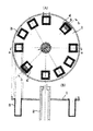
図1及び図2は、本発明の一実施例を示すものであり、円盤状反応ディスク1は、中心に立設した回転軸2によって回転自在に形成され、その周縁部には、対向した分離用セル4,4´と多数の反応用セル(測定用セル)3とが直立状態(垂直若しくは略垂直)で独立して設けられている。
【0019】
反応用セル3は、図1(B)に示すように、垂直に設けられている。斜めに設置すると、反応用セル3の光路の長さを一定に保つのが極めて難しくなる。反応後の分析・測定を精度良く行うためには、反応用セルの光路の長さを一定に保つ必要があるからである。
【0020】
分離用セル4,4´も図2(A)に示すように、垂直に設けられている。分離用セルを斜めに設置すると、遠心分離後上清を吸引するのが困難になるほか、装置内に余分のスペースが必要となり、装置がその分大きくなる。そればかりか、反応用セル3を恒温に保つのに効率が悪くなり、測定用ランプと受光部位置決めが面倒になるほか、反応用セル及び分離用セルの成型が難しくなり、コストアップにつながるなどの欠点が生じる。
【0021】
分離用セル4,4´の上端開口には、開口5を部分的に覆う蓋体6が設けられている。開口5全体に蓋をしないのは、懸濁液の分注及び上清採取のためのプローブを挿入させるから(プローブが挿入できるスペースが必要であるから)である。従って、開口5を部分的に覆う蓋体6としては、蓋体6にプローブを挿入し得る開口を形成したものでも良い。
【0022】
分離用セル4,4´は、図2及び図3に示すように、小さな断面の不溶物収集部7の上に大きな断面の上清分離部8を連通するように連結して構成され、該連結部の段部を棚部9としている。不溶物収集部7のディスク1中心に向く面が段部に形成され、反対側の外方に向く面は平坦に形成されている。
【0023】
蓋体6は、少なくとも不溶物収集部7の開口を覆う大きさとするのが好ましく、蓋体6で覆われていない開口5は、棚部9と対向するようにするのが、不溶物が遠心分離中流出しないようにし易いことから好ましい。蓋体6にプローブを挿入し得る開口を形成した場合は、同開口が棚部9と対向するようにするのが好ましい。
【0024】
図2(B)及び図3(A)に示すように、分離用セル4,4´は、断面扇形又は台形に形成されている。これは必ずしもこのようでなくとも良いが、ディスク1の内方に向かって先細となるような形状とするのが好ましい。不溶物収集部7をある程度の大きさとして、上清分離部8に上清のみが蓄積されるような構造とすることで、上清の分取が容易となるからである。
【0025】
例えば、従来は、採血した血液を採血管ごと遠心分離機にかけている。このときの血液量は少なくとも5mL以上はあるので、分離後に上清(血漿等)をμL単位で採取することはさほど困難ではない。また最近の採血管には血球と血漿等の間に分離剤が入り込んで血球の舞い上げを防止する機能がついたものもある。本発明では全体の小型化を実現するため、400μL程度の試料でも支障なく実施できるように形成することを意図している。分離によって400μL程度の試料から得られる血漿等は200μL程度であるので、従来の分離用セルでは血球を舞い上げずに血漿等を分取することは、極めて困難である。
【0026】
本発明では、分離用セル4,4´の内側(遠心時に血球(不溶物)が押しつけられない側)に棚9を設置することで、遠心分離後に棚9上に溜まる試料が血漿等(上清)のみとなるから、分取する際に血球等(不溶物)の舞い上げ防止が達成できる。
【0027】
本発明のように分離用セル4,4´を垂直に設置して懸濁液を遠心分離する場合、遠心分離中、不溶物は外側に上清は内側(ディスクの中心側)に徐々に移動する。従って、棚9は必ず分離用セル4,4´の内側(遠心時に不溶物が押しつけられない側)に設置する必要があり、逆にすると棚9がない場合と同じこととなる。
【0028】
蓋体6は必ずしも分離用セルの上端に設ける必要はないが、分離できる懸濁液の量は蓋体6の位置と不溶物収集部7と8のスペースの和で決まる。従って、容量を最大限にするためには蓋体6の位置は上端が好ましく、セルの成形の容易さを考慮すると上端に位置するのが好ましい。不溶物収集部7の容量は目的とする懸濁液中の不溶物の量によって決定され、不溶物が上清分離部8のスペースに混入しないような容量が要求される。目的とする懸濁液の量と当該懸濁液中の不溶物の量により、棚体9の高さが決定される。
例えば懸濁液が血液である場合、血液のヘマトクリットの差により血球(不溶物)収集部7の容量も決まるので、ヘマトクリットが高い血液でも血球(不溶物)が不溶物収集部7内に納まるように、この容量を決定する必要がある。
【0029】
次に、上記反応ディスクを使用し、懸濁液から上清を分離し、分離した上清中の成分を分析する方法を説明する。尚、上清中の目的物の分析として目的物濃度を測定する場合を例にとり説明する。
【0030】
まず、図1及び図2に示す分離用セル4,4´の蓋体6で覆われていない開口5から所定量の懸濁液(例えば血液)を分注用プローブから注入する。それからモータを回転させて、回転軸2を高速回転させ、遠心分離する。
【0031】
遠心力は、分離用セルの底ではなく、側面に働くので、遠心分離中、不溶物(例えば血球)は外側に上清(例えば血漿)は内側(ディスクの中心側)に徐々に移動する。蓋体6を設置したことで、遠心分離中の懸濁液(例えば血液)の飛び出しは全く観察されなかった。
【0032】
モータの回転を停止させると、図3に示すように、棚9より上方の上清(例えば血漿)と下方の不溶物(例えば血球)とに分離した。図3に示すように、棚9が上清(例えば血漿)と不溶物(例えば血球)の境界面より上方の位置に(最大でも一致)くるように構成する必要がある。
【0033】
それから、分注用プローブを図3の開口5から挿入して、上清(例えば血漿)部分を分取し、反応用セル3に分注する。上清(例えば血漿)は棚9の上方に位置しているので、不溶物(例えば血球)が舞い上がることを防止できた。
【0034】
図示していないが、反応ディスク1に隣接して試薬ディスク(図示省略)が設けられ、分注用プローブ10(注:図4参照)が試薬ディスクと反応ディスク1との間を往復し、反応セル3中に試薬を供給するようになっている。この際、モータを回転させて、反応セル3を分注用プローブ10で分注し得る位置まで移動させるようになっている。
【0035】
モータは、分離用セルを回転させる場合はモータが高速回転に、測定用セルを回転移動させる場合はモータが位置決め用回転になるようにする。これは、単一のモータの回転速度を変換するか、分離用と測定用のモータを切替えて使用すれば良い。上記実施例では、高速回転用(分離用)モータと位置決め用モータ(測定用)とを、クラッチによって、分離用セルの回転軸と測定用セルの回転軸のいずれかを回転させるように、切替えるようになっている。例えば、クラッチがつながった状態では、高速回転用モータが分離用セルの回転軸を回転させ、クラッチが離れた状態では、位置決め用モータの回転が測定用セルの回転軸を回転させるようにすれば良い。また、単一のモータの回転速度を変換する場合には、分離用セルを回転させる場合はモータが高速回転し得、測定用セルを回転移動させる場合はモータが位置決め用回転となるように低速回転し得るように、モータ自体の回転速度を変換しても、或いは、モータ自体の回転速度は変換せずに適当なギアやベルト等を組み合わせて反応ディスクの回転速度を変換し得るようにしてもよく、この分野の常法に準じて行われる。
【0036】
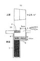
試薬を供給することによって、上清(例えば血漿)と試薬との反応が起きる。反応により変化した光学濃度を従来と同じように、図4に示す光度計で測定する。
図4において、反応ディスク1の反応用セル3は、反応用ブロック(恒温槽)11内に収容され、反応用セル3を所定の恒温状態に維持するようになっている。
【0037】
ランプ12からの光がレンズ13を通って、反応用ブロック11の光照射用窓14から、反応用セル3に照射され、反応用セル3を通過し、ミラー15を通った光を分光部ファイバ16から取り出し、そのデータに基づいて吸光度を求め、その吸光度に基づいて目的成分の濃度を測定する。目的物の濃度測定は、標準を用いたり、吸光度と目的物濃度の関係を示す検量線を用いる等の、この分野の常法に準じて行われる。
【0038】
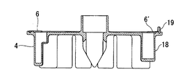
図5及び図6は、本発明の他の実施例を示すものであり、分離用セル4と対向して希釈用セル18が直立状態(垂直若しくは略垂直)で独立して設けられている。分離用セル4で分離された上清みの所定量を反応用セル3に入れ、要すれば、希釈用セル18内の希釈液で希釈し、更に試薬を供給して反応させるようになっている。希釈用セルを斜めに設置すると、希釈液を吸引するのが困難になる等、分離用セルを斜めに設置した場合の欠点と同様の欠点が生じる。希釈用セル18内は、特に必要が無いので、分離用セル4内のように段部9に形成されていない。
希釈用セル18は、必ずしも分離用セル4と対向した位置に設置する必要はないが、遠心分離の際のディスクの回転バランスを取ることが容易となるので、分離用セル4の対向した位置に設けるのが好ましい。
また、希釈用セル18は、該希釈用セルの内部に希釈液を保持させた場合(希釈液が分注された場合)の重量(遠心分離の際の重量)が、懸濁液(例えば血液等)を内部に保持した分離用セル(懸濁液が分注された分離用セル4)の重量(遠心分離の際の分離用セル4の重量)と同程度となるように、その形状や材質等を考慮に入れて形成するのが好ましい。
尚、分離用セル4で分離された上清みを希釈液で希釈する必要がない場合〔即ち、希釈用セル18を必要としない場合や希釈用セル18に希釈液を保持させておく(分注する)必要がない場合〕であっても、上記の理由から、分離用セル4と対向した位置に希釈用セル18を設置し、懸濁液(例えば血液等)を内部に保持した分離用セル(懸濁液が分注された分離用セル4)の重量と同程度となるように、該希釈用セル18の内部に希釈液を保持させて(分注して)、遠心分離を行っても良い。
【0039】
希釈液としては、水、生理食塩水、通常この分野で用いられている例えばトリス緩衝液、リン酸緩衝液、ベロナール緩衝液、ホウ酸緩衝液、グッド緩衝液等の緩衝液が挙げられる。
【0040】
希釈用セル18の上端開口には、分離用セル4と同様に開口を部分的に覆う蓋体6´が設けられている。開口全体に蓋をしないのは、希釈液の採取のためのプローブを挿入させるため(プローブが挿入できるスペースが必要であるため)である。開口を部分的に覆う蓋体6´は、前記と同様に蓋体6´にプローブを挿入する開口を形成したものでも良い。
図5に示すように、希釈用セル18も、断面扇形又は台形に形成されている。これは必ずしもこのようでなくても良いが、ディスク1の内方に向かって先細となるような形状とするのが好ましい。
蓋体6´の開口側の反対側の端部は、上方に起立した折曲部19に形成されている。この折曲部19は、必ずしも希釈用セル18に形成させなくても良く、例えば分離用セルの蓋体6の開口側の反対側の端部や1つの測定用セル等ディスク1の少なくとも1箇所に形成されていれば良い。
【0041】
この折曲部19は、ディスク1の位置合わせ(原点の設定)のためのものである。ディスク1の周囲の一箇所にセンサ(図示省略)が設置され、ディスク1が回転すると、センサがこの折曲部19を検知し、所定の位置で停止するようになっている。この停止位置をディスク1の原点としている。
【0042】
ディスク1を置いた直後や遠心した後は、ディスク1がどの位置にあるのか装置にはわからないので、この原点出しが必要になる。例えば、ディスク1の周囲に高さ5mmほどの壁を作って、希釈用セル10の部分だけ壁を作らない方法によるなど、他の手段によっても同様の効果は得られる(原点出しはできる)ので、折曲部19は必ずしも必要ではない。
【0043】
本発明において、「上清中の目的物を分析する」とは、上清中に存在する目的物の量を測定(定量)すること、当該目的物の量を大まかに測定(半定量)すること、及び上清中の目的物の存在の有無を検出(定性)することである。
【0044】
本発明により分離された上清中の目的物を分析するには、例えば化学的測定法、酵素学的測定法、免疫学的測定法等の例えば臨床検査分野、生化学分野、生物分野、化学分野、食品分野等で通常行われている方法(例えば国際公開第03/018614号パンフレット、臨床検査法提要改訂
第30版,平成5年12月20日,第2刷発行,金原出版(株)等)に準じて行えばよい。また、本発明において用いられる試薬も上記した如き分野及び方法で通常用いられているものが使用でき、目的物の種類や分析方法により適宜選択すればよい。
【図面の簡単な説明】
【0045】
【図1】本発明の反応ディスクの一実施例を示す(A)平面図、(B)a―a断面図である。
【図2】(A)図1(A)のb―b断面図、(B)図2(A)のみの反応ディスクの平面図である。
【図3】本発明の分離用セルの一実施例を示す(A)平面図、(B)断面図である。
【図4】血漿と試薬との反応により変化した光学濃度の測定装置の一例を示す断面図である。
【図5】本発明の他の実施例を示す斜視図である。
【図6】図5の断面図である。
【符号の説明】
【0046】
1・…………反応ディスク
2・…………回転軸
3・…………反応用セル(測定用セル)
4,4´・…………分離用セル
5・…………開口
6,6´・…………蓋体
7・…………血球収集部
8・…………血漿分離部
9・…………棚部
10・………分注用プローブ
11・………反応用ブロック
12・………ランプ
13・………レンズ
14・………光照射用窓
15・………ミラー
16・………分光部ファイバ
17・………モーター
18・………希釈用セル
19・………折曲部【Technical field】
[0001]
The present invention, for example, relates a suspension such as blood into insolubles and is analyzed predetermined component contained like in the supernatant plasma and the like obtained by removing blood cells (measured) to the reaction disc for an automatic analyzer if Shoki relates to a reaction disk in order to reduce the size of an automatic analyzer for measuring a target concentration in plasma or the like.
[Background]
[0002]
Conventionally, various types of analytical instruments for quantitatively analyzing components contained in a sample solution such as plasma have been put into practical use.
[0003]
This type of conventional apparatus separates plasma or the like from whole blood by a centrifugal separation process or a filtration process as a pretreatment, and analyzes the separated plasma or the like as a sample solution.
[0004]
Conventionally, when performing a centrifugation process, the separation cell is usually installed obliquely. For this reason, when adding a function to cause the automatic analyzer to perform a centrifugal separation process, the separation cell is installed obliquely, or a swing type in which the cell is oblique during the centrifugal separation is adopted. If the cell and the reaction cell are provided on one disk, the structure becomes complicated or the apparatus has to be enlarged for mounting the disk. In some cases, the separation disk is installed separately from the reaction disk. In this case, however, the apparatus becomes large and cannot be downsized, and the cost is increased.
DISCLOSURE OF THE INVENTION
[Problems to be solved by the invention]
[0005]
It would be very convenient if we could immediately separate plasma from blood collected from patients in hospital rooms, etc., and quantitatively analyze the components in plasma, etc., but it has both a centrifuge function and a function to measure specific components (reaction function). If this is the case, the conventional apparatus would be large, so it was extremely unsuitable for use for this purpose.
[0006]
The inventions may, aims to provide a reaction disk capable and compact and inexpensive automatic analyzer to allow immediate quantitative analysis of components in suspension, such as blood collected from the patient in the hospital's room, etc. you.
[Means for Solving the Problems]
[0007]
If a conventional separation cell and measurement cell are installed on the same reaction disk, the separation cell is installed diagonally or is inclined during rotation. And the cost is high because the disk cannot be integrally molded. For this reason, the separation cell and the measurement cell are not conventionally arranged on the same disk in a manner in which separation and measurement are completely independent.
[0008]
In order to achieve the above-mentioned object, the present inventors have conducted intensive research and as a result, the separation cell is centrifuged in the same upright state as the rotating shaft, and the suspension of blood or the like does not easily flow out even if it is centrifuged in the upright state. As a result, the inventors have reached the present invention in which a separation cell and a measurement cell are provided on the same reaction disk.
[0009]
That is, according to the first aspect of the present invention, the separation cell and the measurement cell are provided on the same reaction disk so that they can be kept upright while both are rotating. The suspension is formed so that it does not flow out during separation, and the supernatant is added to the separation cell and separated by centrifugation. The supernatant is dispensed into the measurement cell, and the target substance in the supernatant is analyzed. It is characterized by doing so.
[0010]
When rotating the separation cell, convert the rotation speed of a single motor so that the motor rotates at high speed, and when rotating the measurement cell, the motor rotates at low speed (for positioning), It is preferable that the motor can be switched between a separation motor and a measurement motor.
[0011]
An insoluble matter collecting part is provided in the separation cell, and a lid part is provided on the upper part of the separating cell above the insoluble matter collecting part so as to prevent the suspension from flowing out during centrifugation. 3).
In addition to the separation cell and the measurement cell, the reaction disk is further provided with a dilution cell so that it can be kept upright during rotation, and the dilution cell does not flow out during centrifugation. It is also possible to dilute the supernatant by dispensing the diluent in the dilution cell into the measurement cell (claim 4). In addition, it is good to provide the cover body which covers partially so that a dilution liquid may not flow out during centrifugation at the upper part of this cell for dilution.
The cell for separating insoluble matter from the suspension of the present invention is provided with a shelf in the cell, the lower portion of the shelf is an insoluble matter collecting portion, the upper portion is a supernatant separating portion, and the upper portion of the cell above the insoluble matter collecting portion is , covered with a partially lid as suspension centrifuged does not flow out, it characterized in that it is used in an upright state during centrifugation.
[0012]
A small section insoluble matter collecting part and a large section supernatant separating part are connected up and down so that both communicate with each other to form a separation cell, and the other side part of the connecting part is a shelf part. and then, partially have the preferred covering with lid over the separation cell above the insoluble matter collection unit. The need to provide a ledge on a separation cell toward the center of rotation there Ru.
【The invention's effect】
[0013]
According to the present invention , the separation cell and the measurement cell are provided on the same reaction disk so that both can be kept upright while rotating. Therefore, the automatic analyzer equipped with the cell can be reduced in size and cost. Therefore, it is extremely suitable as an apparatus for immediately separating a supernatant such as plasma from a suspension of blood or the like collected from a patient in a hospital room or the like and analyzing components in the supernatant.
[0014]
In addition, if the separation cell is configured as described above, the suspension can be easily prevented from flowing out during centrifugation, and the supernatant can be separated without mixing insoluble matter even with a small amount of sample. The cell can be made small and inexpensive.
[0015]
The present invention can be applied to suspensions containing insoluble matter. Examples of such suspensions include body fluids such as blood, such as excreta (feces, etc.), biological samples (sputum, pus, skin-derived materials, lymphocytes, blood cells, cell-derived materials, tissue-derived materials, these Etc.), environmental samples (food, beverages, tap water, seawater, lake water, river water, factory effluent, etc.), plant-derived samples (plant tissue, cells, cultures of these, etc.) ), Microorganism-derived samples (various bacteria, viruses, cultures thereof, those obtained by crushing them), and water or the one usually used in this field such as Tris buffer, Examples thereof include suspensions obtained by suspending in a buffer solution such as a phosphate buffer solution, veronal buffer solution, borate buffer solution, and Good's buffer solution.
[0016]
That is, the present invention is based on the above suspension from, for example, blood cells, blood coagulation factors (for example, fibrinogen, prothrombin, factor V, factor VIII, etc.), platelets, undigested materials, cells, tissues, bacteria, viruses, these It is useful for removing insoluble matters such as crushed material and separating / sorting supernatants such as plasma, serum, various extracts and culture supernatants. In particular, it is useful for removing insoluble matters such as blood cells from blood and separating and sorting plasma, and for removing insoluble matters such as blood cells and some blood coagulation factors from blood and separating and sorting serum. And is particularly useful when separating and sorting plasma.
In the case of separating plasma from blood according to the present invention, it is preferable to remove not only blood cells but also platelets as insoluble matter. However, platelets are not completely removed as long as they do not hinder subsequent analysis. There is no problem.
BEST MODE FOR CARRYING OUT THE INVENTION
[0017]
Next, embodiments of the present invention will be described with reference to the drawings.
[0018]
1 and 2 show an embodiment of the present invention, and a disc-
[0019]
As shown in FIG. 1B, the
[0020]
The
[0021]
A
[0022]
As shown in FIGS. 2 and 3, the
[0023]
The
[0024]
As shown in FIGS. 2B and 3A, the
[0025]
For example, conventionally, collected blood is centrifuged together with a blood collection tube. Since the blood volume at this time is at least 5 mL, it is not very difficult to collect a supernatant (plasma, etc.) in μL after separation. In addition, some recent blood collection tubes have a function of preventing the blood cells from rising by the separation agent entering between the blood cells and plasma. In the present invention, in order to realize the overall miniaturization, it is intended that the sample of about 400 μL can be formed without any trouble. Since plasma or the like obtained from a sample of about 400 μL by separation is about 200 μL, it is extremely difficult to sort plasma or the like without raising the blood cells with a conventional separation cell.
[0026]
In the present invention, by installing the shelf 9 inside the
[0027]
When the
[0028]
The
For example, when the suspension is blood, the volume of the blood cell (insoluble matter)
[0029]
Next, a method for separating the supernatant from the suspension using the reaction disk and analyzing the components in the separated supernatant will be described. An example of measuring the concentration of a target as an analysis of the target in the supernatant will be described.
[0030]
First, a predetermined amount of suspension (for example, blood) is injected from the dispensing probe through the opening 5 that is not covered with the
[0031]
Since the centrifugal force acts on the side rather than the bottom of the separation cell, during centrifugation, insoluble matter (for example, blood cells) gradually moves to the outside, and supernatant (for example, plasma) gradually moves to the inside (center side of the disk). By installing the
[0032]
When the rotation of the motor was stopped, as shown in FIG. 3, it was separated into a supernatant (for example, plasma) above the shelf 9 and an insoluble matter (for example, blood cells) below. As shown in FIG. 3, the shelf 9 supernatant (e.g. plasma) and insoluble matter (e.g. blood cells) (matching at most) to a position above the interface it must be configured to come there Ru.
[0033]
Then, a dispensing probe is inserted from the opening 5 in FIG. 3, and a supernatant (for example, plasma) portion is collected and dispensed into the
[0034]
Although not shown, a reagent disk (not shown) is provided adjacent to the
[0035]
When the separation cell is rotated, the motor is rotated at a high speed, and when the measurement cell is rotated, the motor is rotated for positioning. This can be done by converting the rotational speed of a single motor or switching between a separation motor and a measurement motor. In the above-described embodiment, the high-speed rotation (separation) motor and the positioning motor (measurement) are switched by the clutch so that either the rotation axis of the separation cell or the rotation axis of the measurement cell is rotated. It is like that. For example, when the clutch is engaged, the high-speed rotation motor rotates the rotation axis of the separation cell, and when the clutch is disengaged, the rotation of the positioning motor rotates the rotation axis of the measurement cell. good. Also, when converting the rotation speed of a single motor, the motor can rotate at a high speed when the separation cell is rotated, and when the measurement cell is rotated, the motor is rotated at a low speed so that the motor is rotated for positioning. Even if the rotational speed of the motor itself is converted so that it can be rotated, or the rotational speed of the reaction disk can be converted by combining appropriate gears and belts without converting the rotational speed of the motor itself. Well, it is done according to the usual method in this field.
[0036]
By supplying the reagent, a reaction between the supernatant (eg, plasma) and the reagent occurs. The optical density changed by the reaction is measured with a photometer shown in FIG.
In FIG. 4, the
[0037]
The light from the
[0038]
5 and 6 show another embodiment of the present invention, in which a
The
In addition, the
It should be noted that when it is not necessary to dilute the supernatant separated in the
[0039]
Examples of the diluent include water, physiological saline, and buffer solutions such as Tris buffer, phosphate buffer, veronal buffer, borate buffer, and Good's buffer that are usually used in this field.
[0040]
The upper end opening of the
As shown in FIG. 5, the
The end of the
[0041]
The
[0042]
Immediately after placing the
[0043]
In the present invention, the term "analyzing the desired product in the supernatant", measuring the amount of target compound present in the supernatant (quantitative) to be roughly measuring the amount of the target product (Hanjo amount) And detecting (qualitatively) the presence or absence of the target substance in the supernatant.
[0044]
In order to analyze the target substance in the supernatant separated according to the present invention, for example, chemical measurement method, enzymological measurement method, immunological measurement method, etc., for example, clinical laboratory field, biochemical field, biological field, chemical field Methods commonly used in the field, food field, etc. (for example, International Publication No. 03/018614 pamphlet, Clinical Examination Law Revision 30th Edition, December 20, 1993, Second Printing, Kanehara Publishing Co., Ltd.) Etc.). In addition, the reagents used in the present invention may be those commonly used in the fields and methods as described above, and may be appropriately selected depending on the type of target product and the analysis method.
[Brief description of the drawings]
[0045]
FIG. 1A is a plan view and FIG. 1B is a cross - sectional view along line aa showing one embodiment of a reaction disk of the present invention.
2A is a cross - sectional view taken along the line bb of FIG. 1A, and FIG. 2B is a plan view of the reaction disk of FIG. 2A only.
3A is a plan view and FIG. 3B is a cross-sectional view showing an embodiment of a separation cell according to the present invention.
FIG. 4 is a cross-sectional view showing an example of an apparatus for measuring optical density changed by the reaction between plasma and a reagent.
FIG. 5 is a perspective view showing another embodiment of the present invention.
6 is a cross-sectional view of FIG.
[Explanation of symbols]
[0046]
1 ·········
4, 4 '········ Separation cell 5 ····································································· ............
Claims (8)
Applications Claiming Priority (3)
| Application Number | Priority Date | Filing Date | Title |
|---|---|---|---|
| JP2003408523 | 2003-12-08 | ||
| JP2003408523 | 2003-12-08 | ||
| PCT/JP2004/018209 WO2005057224A1 (en) | 2003-12-08 | 2004-12-07 | Automatic analyzer-use reaction disc and separating cell |
Publications (2)
| Publication Number | Publication Date |
|---|---|
| JPWO2005057224A1 JPWO2005057224A1 (en) | 2007-07-05 |
| JP4055802B2 true JP4055802B2 (en) | 2008-03-05 |
Family
ID=34674877
Family Applications (1)
| Application Number | Title | Priority Date | Filing Date |
|---|---|---|---|
| JP2005516125A Expired - Fee Related JP4055802B2 (en) | 2003-12-08 | 2004-12-07 | Reaction disk for automatic analyzer |
Country Status (5)
| Country | Link |
|---|---|
| US (1) | US7722812B2 (en) |
| EP (1) | EP1693675A4 (en) |
| JP (1) | JP4055802B2 (en) |
| CN (1) | CN1890569B (en) |
| WO (1) | WO2005057224A1 (en) |
Families Citing this family (10)
| Publication number | Priority date | Publication date | Assignee | Title |
|---|---|---|---|---|
| JP4944970B2 (en) * | 2008-01-15 | 2012-06-06 | 協和メデックス株式会社 | Centrifugal separation device and method for preparing measurement sample using the same |
| US10457975B1 (en) * | 2016-02-10 | 2019-10-29 | William George Pitt | Hollow rotating device for separating particles from blood |
| EP3229028B1 (en) | 2016-04-08 | 2021-11-10 | I-Sens, Inc. | Circular type cartridge enabling centrifugation and modular automatic analyzer using the same |
| KR101970790B1 (en) * | 2017-03-21 | 2019-04-19 | 주식회사 아이센스 | Method and apparatus with improved accuracy |
| KR101860744B1 (en) | 2016-04-08 | 2018-05-24 | 주식회사 아이센스 | Method and apparatus with improved accuracy |
| CN107966578B (en) * | 2017-12-26 | 2024-01-02 | 江苏柯伦迪医疗技术有限公司 | Medical rapid biochemical detection system and detection method |
| CN109188007B (en) * | 2018-09-06 | 2022-04-12 | 桂林优利特医疗电子有限公司 | Reaction disc of full-automatic biochemical analyzer and use method thereof |
| US11754576B2 (en) * | 2018-10-08 | 2023-09-12 | Team Conveyer Intellectual Properties, LLC | Coordinated conveyers in an automated system |
| CN109444444A (en) * | 2018-10-10 | 2019-03-08 | 深圳市国赛生物技术有限公司 | A kind of detection analysis instrument and its application method |
| KR102573892B1 (en) | 2019-04-11 | 2023-09-04 | 팀 컨베이어 인텔렉츄얼 프로퍼티스 엘엘씨 | Conveyor Adjustment in Automated Systems |
Family Cites Families (22)
| Publication number | Priority date | Publication date | Assignee | Title |
|---|---|---|---|---|
| US3586484A (en) * | 1969-05-23 | 1971-06-22 | Atomic Energy Commission | Multistation analytical photometer and method of use |
| US3681029A (en) * | 1970-04-13 | 1972-08-01 | Union Carbide Corp | Sample holder and transferring device for a centrifuge |
| BE792516A (en) * | 1971-12-09 | 1973-06-08 | Union Carbide Corp | RAPID SPECTROPHOTOMETRIC ANALYSIS PROCESS |
| JPS5644852A (en) * | 1979-09-21 | 1981-04-24 | Hitachi Ltd | Centrifugal sampler for automatic chemical analysis device |
| DE3044372A1 (en) * | 1980-11-25 | 1982-07-08 | Boehringer Mannheim Gmbh, 6800 Mannheim | ROTOR UNIT WITH INSERT ELEMENTS FOR A CENTRIFUGAL ANALYZER |
| JPS57171266A (en) * | 1981-04-14 | 1982-10-21 | Sunstar Kinzoku Kk | Apparatus for examining mixed reagent |
| ATE34618T1 (en) * | 1982-09-02 | 1988-06-15 | Hettich Andreas Fa | CENTRIFUGATION CHAMBERS FOR THE CYTODIAGNOSTIC PREPARATION OF EPITHELIAL CELLS AND THEIR USE. |
| JPS59210343A (en) | 1983-05-14 | 1984-11-29 | Kokusan Enshinki Kk | Automatic separation and collecting method of serum and its apparatus |
| JPS6230377A (en) | 1985-07-31 | 1987-02-09 | Fujitsu Ltd | Manufacture of amorphous silicon thin film transistor |
| FR2634893B1 (en) * | 1988-07-28 | 1990-09-14 | Guigan Jean | MINIATURE LABORATORY FOR CARRYING OUT BIOLOGICAL ANALYSIS BY CHEMICAL REACTION FROM A BLOOD SAMPLE |
| US5472671A (en) * | 1989-04-26 | 1995-12-05 | Nilsson; Sven-Erik | Cuvette |
| JP2731423B2 (en) * | 1989-06-30 | 1998-03-25 | 日本商事株式会社 | Rotary cuvette |
| JPH03175362A (en) | 1989-09-13 | 1991-07-30 | Chiyoda Seisakusho:Kk | Automatic cell treatment apparatus |
| JPH0360239U (en) | 1989-10-16 | 1991-06-13 | ||
| US5149501A (en) * | 1990-01-29 | 1992-09-22 | Cirrus Diagnostics, Inc. | Multichambered container and instrument for performing diagnostic tests |
| US5252228A (en) * | 1991-11-05 | 1993-10-12 | Wescor, Inc. | Cytocentrifugation device, apparatus, and method |
| US5422018A (en) * | 1994-01-31 | 1995-06-06 | Applied Imaging | Centrifuge tube and adaptor |
| JP3192401B2 (en) * | 1997-04-01 | 2001-07-30 | 和光純薬工業株式会社 | Method for separating liquid sample components and apparatus used for the method |
| JP3962464B2 (en) | 1997-11-21 | 2007-08-22 | 株式会社アイディエス | Sample centrifuge |
| CA2322202C (en) * | 1998-03-10 | 2010-11-30 | Large Scale Proteomics Corporation | Detection and characterization of microorganisms |
| JPH11311592A (en) | 1998-04-27 | 1999-11-09 | Ado Science:Kk | Sample slide formation apparatus |
| CA2334887C (en) * | 1999-04-12 | 2012-01-24 | Harvest Technologies Corporation | Method and apparatus for producing platelet rich plasma and/or platelet concentrate |
-
2004
- 2004-12-07 EP EP04820205.5A patent/EP1693675A4/en not_active Withdrawn
- 2004-12-07 US US10/581,695 patent/US7722812B2/en not_active Expired - Fee Related
- 2004-12-07 CN CN2004800363423A patent/CN1890569B/en not_active Expired - Fee Related
- 2004-12-07 WO PCT/JP2004/018209 patent/WO2005057224A1/en active Application Filing
- 2004-12-07 JP JP2005516125A patent/JP4055802B2/en not_active Expired - Fee Related
Also Published As
| Publication number | Publication date |
|---|---|
| JPWO2005057224A1 (en) | 2007-07-05 |
| CN1890569A (en) | 2007-01-03 |
| US7722812B2 (en) | 2010-05-25 |
| EP1693675A1 (en) | 2006-08-23 |
| EP1693675A4 (en) | 2013-09-18 |
| US20070087429A1 (en) | 2007-04-19 |
| CN1890569B (en) | 2011-03-16 |
| WO2005057224A1 (en) | 2005-06-23 |
Similar Documents
| Publication | Publication Date | Title |
|---|---|---|
| US5149501A (en) | Multichambered container and instrument for performing diagnostic tests | |
| CA2129967C (en) | Reagent container for analytical rotor | |
| US7758815B2 (en) | Specimen collection, storage, transportation and assaying device | |
| CN102281949B (en) | Device and analyzing system for conducting agglutination assays | |
| JP4055802B2 (en) | Reaction disk for automatic analyzer | |
| US20120065047A1 (en) | Centrifuge and separation vessel therefore | |
| JP2011502623A (en) | Transdermal body fluid sampling and pretreatment apparatus and method | |
| JPH03505702A (en) | Multi-analyte test vehicle | |
| KR20020043551A (en) | Disposable Test Vial with Sample Delivery Device | |
| EP0075556A1 (en) | Centrifugal analyzer | |
| JPH08338840A (en) | Method and apparatus for determination of sedimentation velocity of blood | |
| US6016193A (en) | Cuvette holder for coagulation assay test | |
| US5275731A (en) | Apparatus for rapidly separating blood into filtered fractions | |
| JP7361492B2 (en) | Laboratory systems and methods for separating interfering substances contained in test samples | |
| WO1997008555A1 (en) | System and methods for performing rotor assays | |
| KR20130098169A (en) | Diagnostic system and components | |
| WO1999039182A1 (en) | Spectrophotometric analytical cartridge | |
| EP0114874A1 (en) | Container for small quantities of liquids | |
| KR101436168B1 (en) | Blood separating device | |
| JPH11511856A (en) | How to perform a blood test | |
| EP1808687A3 (en) | Absolute measurement centrifuge | |
| WO1994018557A1 (en) | Apparatus for analysing blood and other samples | |
| US20190285524A1 (en) | Methods and devices for processing samples and counting cells | |
| JP2007333716A (en) | Separating/weighing chip, and method for using the same | |
| JP4062549B2 (en) | Cell for separation of insoluble matter from suspension |
Legal Events
| Date | Code | Title | Description |
|---|---|---|---|
| A521 | Written amendment |
Free format text: JAPANESE INTERMEDIATE CODE: A523 Effective date: 20071012 |
|
| A621 | Written request for application examination |
Free format text: JAPANESE INTERMEDIATE CODE: A621 Effective date: 20071012 |
|
| A521 | Written amendment |
Free format text: JAPANESE INTERMEDIATE CODE: A523 Effective date: 20071015 |
|
| A621 | Written request for application examination |
Free format text: JAPANESE INTERMEDIATE CODE: A621 Effective date: 20071012 |
|
| A871 | Explanation of circumstances concerning accelerated examination |
Free format text: JAPANESE INTERMEDIATE CODE: A871 Effective date: 20071012 |
|
| TRDD | Decision of grant or rejection written | ||
| A975 | Report on accelerated examination |
Free format text: JAPANESE INTERMEDIATE CODE: A971005 Effective date: 20071115 |
|
| A01 | Written decision to grant a patent or to grant a registration (utility model) |
Free format text: JAPANESE INTERMEDIATE CODE: A01 Effective date: 20071120 |
|
| A61 | First payment of annual fees (during grant procedure) |
Free format text: JAPANESE INTERMEDIATE CODE: A61 Effective date: 20071203 |
|
| R150 | Certificate of patent or registration of utility model |
Free format text: JAPANESE INTERMEDIATE CODE: R150 |
|
| FPAY | Renewal fee payment (event date is renewal date of database) |
Free format text: PAYMENT UNTIL: 20101221 Year of fee payment: 3 |
|
| FPAY | Renewal fee payment (event date is renewal date of database) |
Free format text: PAYMENT UNTIL: 20131221 Year of fee payment: 6 |
|
| LAPS | Cancellation because of no payment of annual fees |