JP4050365B2 - Oval cleaning box for filling equipment - Google Patents
Oval cleaning box for filling equipment Download PDFInfo
- Publication number
- JP4050365B2 JP4050365B2 JP29885597A JP29885597A JP4050365B2 JP 4050365 B2 JP4050365 B2 JP 4050365B2 JP 29885597 A JP29885597 A JP 29885597A JP 29885597 A JP29885597 A JP 29885597A JP 4050365 B2 JP4050365 B2 JP 4050365B2
- Authority
- JP
- Japan
- Prior art keywords
- filling
- nozzle
- box
- cylinder body
- elliptical cylinder
- Prior art date
- Legal status (The legal status is an assumption and is not a legal conclusion. Google has not performed a legal analysis and makes no representation as to the accuracy of the status listed.)
- Expired - Fee Related
Links
Images


Classifications
-
- B—PERFORMING OPERATIONS; TRANSPORTING
- B65—CONVEYING; PACKING; STORING; HANDLING THIN OR FILAMENTARY MATERIAL
- B65B—MACHINES, APPARATUS OR DEVICES FOR, OR METHODS OF, PACKAGING ARTICLES OR MATERIALS; UNPACKING
- B65B39/00—Nozzles, funnels or guides for introducing articles or materials into containers or wrappers
-
- B—PERFORMING OPERATIONS; TRANSPORTING
- B65—CONVEYING; PACKING; STORING; HANDLING THIN OR FILAMENTARY MATERIAL
- B65B—MACHINES, APPARATUS OR DEVICES FOR, OR METHODS OF, PACKAGING ARTICLES OR MATERIALS; UNPACKING
- B65B2210/00—Specific aspects of the packaging machine
- B65B2210/06—Sterilising or cleaning machinery or conduits
- B65B2210/08—Cleaning nozzles, funnels or guides through which articles are introduced into containers or wrappers
Landscapes
- Engineering & Computer Science (AREA)
- Mechanical Engineering (AREA)
- Filling Of Jars Or Cans And Processes For Cleaning And Sealing Jars (AREA)
- Basic Packing Technique (AREA)
- Cleaning By Liquid Or Steam (AREA)
- Washing And Drying Of Tableware (AREA)
Description
【0001】
【発明の属する技術分野】
本発明は流体充填装置の洗浄箱に関する。より詳しくは、角度付き開口を備えた、楕円形の流体充填装置洗浄箱に関する。
【0002】
【従来の技術】
流体充填装置は種々の工業において、種々の用途に使用されている。かかる装置は特に、例えば、牛乳カートン、果汁箱等のような流動食品包装に充填する流動食品包装工業において広く使用されている。
一般に、流動食品包装システムは、流動食品を貯蔵するための流体貯蔵器またはタンクと、流体を個別の包装へ輸送する流体輸送手段とを有する。典型的構造においては、流体輸送手段は、流動食品を充填ステーションに供給するための一連のポンプ、流体導管、弁を有している。充填ステーションは、柔軟な伝送または充填ノズルを含む。柔軟な充填ノズルが、流体を個々の包装内へと導く。
【0003】
充填ノズルは剛固な充填管の端部に取り付けられている。柔軟なノズルは、充填される容器またはカートンの形状に整合するように開いた四角形断面を有している。通常の構造では、充填管は、充填装置に搭載または固定された搭載板から下方へ延び、垂下している。通常切妻頂部カートンと呼ばれるカートンを充填するために使用される充填装置構造においては、充填管に隣接して案内要素が設けられる。案内要素が、カートンをノズルの下方に位置させ、ノズルをカートン内に適切に位置させることを容易にしている。
【0004】
食品包装工業の性格は、包装システムが高レベルの清潔度を有して維持されることを要求する。従って、設備とシステムとの点検、周期的洗浄、保守が容易であるように、システムの成分を構成することが重要である。
充填装置と関連して、または、充填装置の一部として使用される装置の一つが洗浄箱である。既知の洗浄箱の1形態においては、円形管が下方へ延び、単一の充填管とノズルとを覆い、管とノズルとを洗浄する隔離領域を形成している。この構造は、充填管とノズルとの洗浄には十分であるが、多くの欠点が見られる。第1に、洗浄箱が完全にノズルを取り囲んでいる。従って、管とノズルへのアクセスが困難であり、そのため、完全性または状態を決めるための管とノズルとの点検を困難にする。
【0005】
さらに、円形洗浄箱は1個の充填ノズルしか収容出来ない。さらに、全てのタイプのカートンが、円形洗浄箱を備えた充填装置により充填出来るものではない。特に、切妻から延びるプラスチック飲み口を使用した切妻頂部カートンは、適切に洗浄箱内へ入り、ノズル上に嵌まることはない。
他の既知の洗浄箱形態は、底に機械加工された長方形の開口を備えた細長い長方形の箱を有している。長方形の洗浄箱内に、約6乃至12個の充填ノズルが配置されている。カートンが上方に箱内へ挿入され、ノズルと係合し、つぎに充填される。
【0006】
長方形洗浄箱は多数のノズルを収容し得る形態の隔離領域を提供するが、機械加工の長方形箱の製造コストは禁止的に高い。さらに、箱の形状と大きさのため、全てのタイプのカートンが、この充填装置を使用して充填され得るとは限らない。円形洗浄箱を使用した場合と同様、切妻頂部カートンは機械加工開口を通しては適切に嵌まらない。さらに、円形洗浄箱に類似して、充填管とノズルとが完全に長方形箱内に閉じ込められ、従って、洗浄、保守、点検のためのアクセスが容易でない。
【0007】
長方形洗浄箱を用いても、円形洗浄箱を用いても、充填管とノズルとの点検、洗浄、保守を行うには、設備内の適切な領域にアクセスするため、装置の1個またはそれ以上の主要部分を解体することが必要である。
従って、完全に隔離された領域を提供し、また、複数個の充填ノズルを収容し得る充填装置の洗浄箱に対する必要が依然として存在している。さらに、かかる洗浄箱は、装置の主要部を解体することなく、洗浄、保守、目視点検のために容易にアクセスされ得るようになっている。
【0008】
【本発明の概要】
関連する流動食品充填装置と共に使用される洗浄箱が、角度付き開放端を備えた楕円形シリンダー体を有する。洗浄箱は、少なくとも1個の、好適には1対の細長い垂下充填管をもつ充填装置と共に使用される。洗浄箱は、充填管が垂下する搭載部材を有する。楕円形シリンダーが、充填管に対するシュラウド状の囲いを形成し、充填管を部分的に覆うように搭載部材から延びている。
【0009】
楕円形シリンダーは長手方向軸を有し、楕円形結合部を形成して搭載部材に取り付けられている。楕円形シリンダーの終端部は、長手方向軸に対して角度をなす開口になっている。開口は所定の端部輪郭を有し、充填管が開口近くにおいて長手方向軸に垂直な平面から目視出来るようになっている。
好適実施例において、開口端輪郭は開口の面内に円を描き、平面が長手方向軸に対し45°の角度をなしている。
【0010】
必要に応じ、洗浄箱は密封閉鎖蓋を備え、該蓋は洗浄箱と係合し、充填管と充填ノズルとを洗浄するための隔離環境を形成する。洗浄箱は、例えば、水、酸、アルカリ、消毒剤、洗剤等の洗浄流体を供給するための1個または1個以上のノズルを有している。洗浄箱はまた、洗浄流体を充填管の間に向けるための噴流ノズルを有している。好適実施例においては、排水ノズルと閉鎖蓋とは下向きの傾斜、すなわち、排水のための傾斜を有している。入口ノズルは、流入して来る洗浄流体に渦巻き運動を与えるため、洗浄箱に対して接線をなすように取り付けられている。
本発明の他の特徴、利点は、付図を参照してなされる以下の詳細な説明と、添付の特許請求の範囲とから明らかになろう。
【0011】
【発明の実施の形態】
本発明においては、種々の形態の実施例が可能であるが、ここには、現在好適な実施例が図示され、説明されている、しかし本開示は発明の例示と考えらるべきであり、本発明を、説明した特定の実施例に限定することを意図していないことを理解すべきである。
【0012】
図面特に図1、図2に、本発明の原理に従う楕円形洗浄箱10が示されている。洗浄箱10は、図7と図12a〜図12cに示すように、搭載板12に取り付けられた楕円形シリンダー体11を有し、搭載板は充填装置14に取り付けられている。洗浄箱10は、1本または1本以上の充填管16とノズル18とを部分的に囲い覆うように形成されている。好適実施例においては、図3、図4に示すように、洗浄箱10は洗浄箱内に位置された2本の充填管16a,bを有する。充填管16a,bはそれぞれ、各充填管16a,bの端部に取り付けられた充填ノズル18a,bを有する。
本体部分11は楕円形の、シュラウド状の、中空シリンダー部材であり、搭載板12から懸吊されて取り付けられている。図面特に図3〜図6から明らかなように、本体11の楕円形状は、既知の円形および四角形輪郭の洗浄箱に勝る多くの利点を備えている。
【0013】
先ず、既知の円形箱と比較して、楕円形本体11は、複数個、例えば2個の充填管16a,bを単一の洗浄箱10内に覆い得る十分な断面積を有する。これは、各充填装置に必要な洗浄箱の全体数を減少させ、設備の全体コストを低下させる。さらに、図5に示すように、洗浄箱10は、切妻頂部カートンCに通常見られるねじプラスチック飲み口Sのような射出成型飲み口SをもつカートンCを収容するように形成されている。
長方形箱とは違い、楕円形洗浄箱10は、隅溶接を必要としない。隅溶接は、溶接の極端な熱による撓曲(反り)、湾曲を防ぐための配慮を要するため、洗浄箱の製造コストを上昇させる。さらに、長方形箱とは異なり、楕円形洗浄箱10は、切妻にプラスチック飲み口Sをもつ切妻頂部カートンCを収容することが出来る。
【0014】
図5、図7は洗浄箱10の側面図である。洗浄箱10は、開口20を横切る平面P0 を画定する角度付き底開口20を有する。好適な形態において、各充填管16a,bとノズル18a,bとの一部が洗浄箱10の底22において露出されている。すなわち、平面P0 を横切るノズル18a,bと管16a,bとの一部が開口20により限定されている。有利な態様で、本発明の洗浄箱10の角度付き開口20が、充填ノズル18a,bの目視点検を容易にし、さらに、装置14の1個または1個以上の主要部分を解体することなく、例えばノズル交換のような日常保守を可能にしている。ノズル18a,bは一般に、自動化充填運転中に破損され兼ねない市販の、食品等級(food grade)の、柔軟なゴム材料で作られているから、充填ノズル18a,bを容易に点検出来ることは、かかる目視点検能力を欠く既知の洗浄箱に勝る顕著な改良である。有利な態様で、ノズルを容易に目視点検出来ることは、充填機械14の点検、保守時の時間とコストとを顕著に省略させ、設備の休止時間を大きく減少させることが出来る。
【0015】
さらに、角度付き開口20に平行な平面における箱10の底を示す図6に示すように、開放底22は円形断面を呈している。すなわち、角度付き開口20が開口20の平面P0 において円Rを描いている。有利な態様で、円形底開口20は、ここに述べる円形閉鎖蓋の使用を可能にし、円形蓋の製造コストは非常に低く出来る。
洗浄箱10の断面を示す図7を参照し、本体11は、装置14の一部に、好適にはフレーム部分26に取り付けられた搭載板12に取り付けられている。搭載板12は、充填ノズル18a,bに対して矢印28で示した(図5)2個の直径的に反対側の隅の近くで下方へ延びる複数個の案内棒または案内ピン30、32を有している。案内ピン30、32が、カートンCを装置14内に適切に位置させ、充填ノズル18a,bをカートンCと適切に係合させることを容易にする。現在の実施例においては、2対の案内ピン30、32が各充填管16a,bと関連している。
【0016】
各対の案内ピン30、32は、34で示された隙間を有して互いに僅か離隔されており、充填管16a,bの長手方向軸At に平行なそれぞれ長手方向軸Ap を有して搭載板12から垂下して位置されている。ピン30、32の各対の軸Ap は、カートンCがそれぞれのノズル18a,bと係合する位置に置かれたとき、充填ノズル18a,bとカートンCとの対向する隅を横切る平面Pt に平行な平面Pp を画定している。かくて、ピン30、32に隣接するカートンCの2個の対向する隅がほぼピン30、32に衝接して位置され、カートンCをその位置に固定する。案内ピン30、32はテーパー端36を有し、カートンCを円滑に受容し、その位置に案内することを容易にしている。案内ピン30、32は搭載板12内の孔38内に嵌められ、溶接される。
【0017】
図7、図9に示すように、搭載板12は、搭載板12と本体11との結合部近くに形成された楕円形の溝材(channel)40を有する。本実施例において、溝材40は、本体11を搭載板12に取り付ける結合部において密封を形成するように、Oリング等の密封要素を受容するように形成されている。洗浄箱10は、洗浄箱10を搭載板12に取り付けるための外側に延びるフランジ44を有する。搭載板12と箱10とは、ボルト46等のファスナーを用いて装置14に取り付けられる。
搭載板12は、充填管16a,bを受容する開口48を有する。充填管16a,bと搭載板12とは、例えば共通の搭載ブラケット50を用いて装置14に共通に取り付けられ、洗浄箱10内における充填管16a,bの整列を容易にしている。Oリング52は搭載板12と充填管16a,bとの結合部に置かれ、管16a,bと板12との間を密封している。
【0018】
図11と図12a〜図12cとに良く見られるように、洗浄箱10は箱に関連する密封閉鎖蓋24を有する。蓋24は、補足的な円形状を有する。当業者には分かるように、円形蓋24は楕円形蓋に比較して、製造コストが顕著に低い。これは、丸くない蓋の製造上の困難さに加えて、既知の洗浄箱構造に勝る楕円形洗浄箱形態の実質的利点を提供している。
【0019】
好適実施例において、蓋24は周縁に、Oリング等の密封要素を受容する溝材58を有する。かくて、蓋24が洗浄箱10上に位置したとき、密封された洗浄環境が形成される。図12a〜図12cに示すように、蓋24は、位置決め錠止装置またはシステム62を用いて、洗浄箱10の開口20上に位置される。システム62は、例えば、蓋24を開口20上に位置させるための、空気的、電気的または機械的に駆動される作動器66を使用した作動構造64を有する。蓋24はまた、蓋24を開口20において洗浄箱10に締結するための周縁フランジ(図示せず)を備えている。
【0020】
図2、図10、図12a〜図12cにおいて、洗浄箱10は入口ノズル68と排水ノズル70とを有する。蓋24が箱10上に置かれ、箱10が密封されると、水などの洗浄流体が洗浄箱10内へ導入される。図示のように、入口ノズル68は本体11に対し接線方向に位置されている。ノズル68を接線方向に位置させることは、洗浄流体に渦巻き運動を起こさせ、それにより、流体の擦り洗い作用を改善し、充填管16a,bとノズル18a,bとに対する洗浄作用を向上させる。
【0021】
好適実施例においては、図12a〜図12cに見るように、排水ノズル70は下向きの傾斜を有している。同様に、蓋24もまた、蓋24が洗浄箱開口20上に位置されたとき、排水ノズル70の方向に一致する下向きの傾斜を有している。かくて、洗浄流体が蓋24と洗浄箱との内部に溜まり、または、蓄積する可能性が低く、箱10と蓋24の排水が向上される。洗浄箱10は、管16a,bの間の洗浄を向上させるため、充填管16a,bの間に洗浄流体を向けるように位置された、典型的噴射ノズル72のような追加のノズルを備えてもよい。
【0022】
当業者には分かるように、楕円形の主軸または直径を通り楕円形シリンダーの長手方向軸と交差する平面にして、平面により画定される断面が円を描くような平面を作成することが出来る。本洗浄箱10においては、洗浄箱10を形成する楕円形シリンダーは、本体11の長手方向軸Ac に対し角度α45°をなす平面の断面形状が円Rとなるような形状を有している。しかし、違った平面角度を使用して円を描きたい場合には、該平面角度に対する楕円の長軸と端軸との間の関係が、該平面角度において円を画定するように決められる。これら角度と直径間の関係は全て本発明の範囲内にある。
【0023】
本関係を楕円形洗浄箱10に対して示す図10において、楕円の周縁上の任意の点のx−y座標は下記等式により表される:
x2 /a2 +y2 /b2 =1
ここで
a:楕円の、x軸に沿った長軸の長さ
b:楕円の、y軸に沿った端軸の長さ
x、yはそれぞれa、bよりも大きくはない。本実施例においては、矢印74、76により示した、楕円形シリンダー体11の各軸の長さa、bの値はそれぞれ118.10mm;83.58mmである。これらa、bの値を用いれば、長手方向軸Ac に対して角度45°をなす平面により画定される断面が円形を描くことになる。楕円形シリンダーの長軸と短軸の長さの比と、円形を描く断面平面の角度αとの間の関係は、 b=asinα として表される。
【0024】
上記関係から、楕円の長軸を含み、長手方向軸と所定の角度αをなして交差する断面が円形を描くような楕円形シリンダーの形状が決められる。
上述のことから、多くの修正と変形とが、本発明の新規な概念の要旨と範囲から外れることなく行われ得ることが分かろう。説明した特定の実施例は、発明の限定を意図したものではなく、また限定と想定されるべきでもないことを理解すべきである。本開示は、これら変形を特許請求の範囲の範囲にあるものとして特許請求の範囲によりカバーすることを意図している。
【図面の簡単な説明】
【図1】本発明の原理を具体化した楕円形洗浄箱の側面図であり、洗浄箱が角度付き開放端を有し、そこから下方へ延びる充填管を示している。
【図2】図1の洗浄箱の底部の透視図であり、洗浄箱は簡単のため充填管が除かれ、箱から延びる入口、噴流、排水の各ノズルが示されている。
【図3】図1の洗浄箱の底部側面の透視図であり、箱内に位置された一対の充填管とノズルとを示す。
【図4】図1の洗浄箱の正面図。
【図5】図1の洗浄箱の底面図であり、充填ノズルと係合した一対のカートンと共に示された洗浄箱の楕円形輪郭を示している。
【図6】洗浄箱開口の輪郭が円を示すような位置から見た洗浄箱の底部透視図。
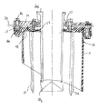
【図7】搭載板と、搭載板に取り付けられた充填管と関連案内ピンとを有して示された図1の洗浄箱の部分断面図。
【図8】充填管と案内ピンとがそこから垂下する搭載板を、簡単のため洗浄箱を除去して示した側面透視図。
【図9】搭載板の底面図。
【図10】図2の洗浄箱の底面図。
【図11】洗浄箱への結合に使用される典型的な閉鎖蓋の側面図。
【図12a】充填装置に取り付けられた洗浄箱と、閉鎖位置にある閉鎖蓋とを示す。
【図12b】充填装置に取り付けられた洗浄箱と、半開放位置にある閉鎖蓋とを示す。
【図12c】充填装置に取り付けられた洗浄箱と、開放位置にある閉鎖蓋とを示す。
【符号の説明】
10 洗浄箱
11 楕円形シリンダー体(本体)
12 搭載板
14 充填装置
16 充填管
18 充填ノズル
20 開口
22 開放底
24 蓋
26 フレーム
30、32 案内ピン
28 隅
40 溝材
62 位置決め錠止装置
68 入口ノズル
70 排水ノズル
72 噴射ノズル
S 飲み口
C カートン
R 円[0001]
BACKGROUND OF THE INVENTION
The present invention relates to a cleaning box for a fluid filling device. More particularly, the present invention relates to an elliptical fluid filling device cleaning box with an angled opening.
[0002]
[Prior art]
Fluid filling devices are used in various applications in various industries. Such devices are particularly widely used in the fluid food packaging industry for filling fluid food packaging such as, for example, milk cartons, fruit juice boxes and the like.
In general, a fluid food packaging system has a fluid reservoir or tank for storing fluid food and a fluid transport means for transporting fluid to individual packages. In a typical configuration, the fluid transport means includes a series of pumps, fluid conduits, and valves for supplying fluid food to the filling station. The filling station includes a flexible transmission or filling nozzle. A flexible filling nozzle directs the fluid into individual packages.
[0003]
The filling nozzle is attached to the end of a rigid filling tube. The flexible nozzle has a square cross section that is open to match the shape of the container or carton being filled. In a normal structure, the filling tube extends downward from a mounting plate mounted or fixed to the filling device and hangs down. In a filling device structure used to fill a carton, commonly referred to as a gable top carton, a guide element is provided adjacent to the filling tube. The guide element facilitates positioning the carton below the nozzle and properly positioning the nozzle within the carton.
[0004]
The nature of the food packaging industry requires that the packaging system be maintained with a high level of cleanliness. Therefore, it is important to configure the components of the system so that inspection, periodic cleaning, and maintenance of the equipment and system are easy.
One of the devices used in connection with or as part of the filling device is a wash box. In one form of known cleaning box, a circular tube extends downward and covers a single filling tube and nozzle to form an isolation region for cleaning the tube and nozzle. While this structure is sufficient for cleaning the fill tube and nozzle, there are many disadvantages. First, the wash box completely surrounds the nozzle. Accordingly, access to the tube and nozzle is difficult, thus making inspection of the tube and nozzle difficult to determine completeness or condition.
[0005]
Furthermore, the circular washing box can accommodate only one filling nozzle. Furthermore, not all types of cartons can be filled by a filling device equipped with a circular washing box. In particular, the gable top carton using a plastic spout extending from the gable will properly enter the wash box and will not fit over the nozzle.
Another known washbox configuration has an elongated rectangular box with a rectangular opening machined in the bottom. About 6 to 12 filling nozzles are arranged in a rectangular washing box. The carton is inserted upwards into the box, engages the nozzle and is then filled.
[0006]
Although rectangular wash boxes provide an isolated area that can accommodate multiple nozzles, the cost of manufacturing a machined rectangular box is prohibitively high. Furthermore, because of the shape and size of the box, not all types of cartons can be filled using this filling device. As with the circular wash box, the gable top carton does not fit properly through the machined opening. Furthermore, similar to a circular cleaning box, the filling tube and nozzle are completely enclosed in a rectangular box, and thus are not easily accessible for cleaning, maintenance and inspection.
[0007]
To check, clean, and maintain the filling tube and nozzles, whether using a rectangular or circular cleaning box, one or more of the equipment is used to access the appropriate area in the facility. It is necessary to dismantle the main part.
Accordingly, there remains a need for a washing box for a filling device that provides a completely isolated area and can accommodate a plurality of filling nozzles. Furthermore, such a cleaning box can be easily accessed for cleaning, maintenance and visual inspection without disassembling the main part of the apparatus.
[0008]
[Outline of the present invention]
A wash box used with an associated fluid food filling device has an elliptical cylinder body with an angled open end. The wash box is used with a filling device having at least one, preferably a pair of elongated drooping filling tubes. The cleaning box has a mounting member on which the filling tube hangs down. An elliptical cylinder forms a shroud-like enclosure for the fill tube and extends from the mounting member to partially cover the fill tube.
[0009]
The elliptical cylinder has a longitudinal axis and is attached to the mounting member forming an elliptical coupling. The end of the elliptical cylinder is an opening that forms an angle with the longitudinal axis. The opening has a predetermined end profile so that the filling tube is visible near a plane perpendicular to the longitudinal axis.
In the preferred embodiment, the open end profile is circular in the plane of the opening and the plane is at an angle of 45 ° to the longitudinal axis.
[0010]
Optionally, the wash box includes a sealed closure lid that engages the wash box and creates an isolation environment for washing the fill tube and fill nozzle. The cleaning box has one or more nozzles for supplying a cleaning fluid such as water, acid, alkali, disinfectant, detergent and the like. The wash box also has a jet nozzle for directing wash fluid between the fill tubes. In the preferred embodiment, the drain nozzle and closure lid have a downward slope, i.e., a slope for draining. The inlet nozzle is mounted tangential to the cleaning box to impart a swirling motion to the incoming cleaning fluid.
Other features and advantages of the present invention will become apparent from the following detailed description, taken in conjunction with the accompanying drawings, and from the appended claims.
[0011]
DETAILED DESCRIPTION OF THE INVENTION
While various forms of embodiments are possible in the present invention, presently preferred embodiments are shown and described herein, but the present disclosure should be considered exemplary of the invention, It should be understood that the invention is not intended to be limited to the specific embodiments described.
[0012]
Referring now to the drawings, particularly FIGS. 1 and 2, an
The main body portion 11 is an oval, shroud-shaped hollow cylinder member that is suspended from the mounting
[0013]
First, compared to a known circular box, the oval body 11 has a sufficient cross-sectional area that can cover a plurality of, for example, two filling
Unlike rectangular boxes, the
[0014]
5 and 7 are side views of the
[0015]
Furthermore, as shown in FIG. 6 which shows the bottom of the
Referring to FIG. 7 showing a cross section of the
[0016]
Guide pins 30, 32 of each pair are slightly spaced from each other with a gap indicated at 34, the
[0017]
As shown in FIGS. 7 and 9, the mounting
The mounting
[0018]
As can be seen in FIGS. 11 and 12a-12c, the
[0019]
In the preferred embodiment, the
[0020]
2, 10, and 12 a to 12 c, the
[0021]
In the preferred embodiment, the
[0022]
As will be appreciated by those skilled in the art, it is possible to create a plane that passes through an elliptical major axis or diameter and intersects the longitudinal axis of the elliptical cylinder such that the cross section defined by the plane is a circle. In the
[0023]
In FIG. 10 showing this relationship for the
x 2 / a 2 + y 2 / b 2 = 1
Here, a: the length of the major axis along the x-axis of the ellipse b: the lengths x and y of the end axes along the y-axis of the ellipse are not larger than a and b, respectively. In the present embodiment, the values of the lengths a and b of the respective axes of the elliptical cylinder body 11 indicated by arrows 74 and 76 are 118.10 mm and 83.58 mm, respectively. Using these values of a, b, cross-section defined by a plane at an angle 45 ° to the longitudinal axis A c is to draw a circle. The relationship between the ratio of the length of the major axis to the minor axis of the elliptic cylinder and the angle α of the circular cross section plane is expressed as b = asin α.
[0024]
From the above relationship, the shape of the elliptic cylinder is determined such that the cross section including the major axis of the ellipse and intersecting the longitudinal axis at a predetermined angle α forms a circle.
From the foregoing, it will be appreciated that many modifications and variations can be made without departing from the spirit and scope of the novel concepts of the present invention. It should be understood that the particular embodiments described are not intended to be limiting of the invention and should not be considered limiting. This disclosure is intended to cover these modifications as falling within the scope of the claims.
[Brief description of the drawings]
FIG. 1 is a side view of an elliptical wash box embodying the principles of the present invention, showing the wash tube having an angled open end and extending downwardly therefrom.
FIG. 2 is a perspective view of the bottom of the washing box of FIG. 1, with the filling box removed for simplicity, showing the inlet, jet, and drainage nozzles extending from the box.
3 is a perspective view of the bottom side of the cleaning box of FIG. 1, showing a pair of filling tubes and nozzles located within the box.
4 is a front view of the cleaning box of FIG. 1. FIG.
FIG. 5 is a bottom view of the wash box of FIG. 1, showing the oval profile of the wash box shown with a pair of cartons engaged with a filling nozzle.
FIG. 6 is a perspective view of the bottom of the cleaning box viewed from a position where the outline of the cleaning box opening shows a circle.
7 is a partial cross-sectional view of the cleaning box of FIG. 1 shown with a mounting plate, a filling tube attached to the mounting plate, and an associated guide pin.
FIG. 8 is a side perspective view showing a mounting plate from which a filling tube and a guide pin depend, with a cleaning box removed for simplicity.
FIG. 9 is a bottom view of the mounting plate.
10 is a bottom view of the cleaning box of FIG. 2. FIG.
FIG. 11 is a side view of an exemplary closure lid used for coupling to a wash box.
Figure 12a shows the wash box attached to the filling device and the closure lid in the closed position.
FIG. 12b shows the cleaning box attached to the filling device and the closing lid in the semi-open position.
Figure 12c shows the wash box attached to the filling device and the closure lid in the open position.
[Explanation of symbols]
10 Washing box 11 Oval cylinder body (main body)
12 Mounting plate 14 Filling device 16
Claims (5)
前記洗浄箱は底開口を有する楕円形シリンダー体を有し、該楕円形シリンダー体は、複数の充填管および充填ノズルを包囲するとともに、該複数の充填管および充填ノズルによりそれぞれ流体を充填される、該複数の充填管と同数の包装容器を前記楕円形シリンダー体の楕円形の長軸方向に並べて収容可能となっており、前記底開口は前記楕円形シリンダー体の長手方向軸に対して傾斜する平面に沿って形成され、該底開口が前記充填ノズルと充填管の一部とを目視可能にしていることを特徴とする洗浄箱。A washing box for washing the filling pipe and the filling nozzle in a fluid filling apparatus comprising a filling pipe having a filling nozzle and filling a packaging container with a fluid,
The washing box has an elliptical cylinder body having a bottom opening, and the elliptical cylinder body surrounds a plurality of filling pipes and a filling nozzle and is filled with fluid by the plurality of filling pipes and the filling nozzle, respectively. The same number of packaging containers as the plurality of filling tubes can be accommodated side by side in the major axis direction of the elliptical cylinder body, and the bottom opening is inclined with respect to the longitudinal axis of the elliptical cylinder body The washing box is formed along a flat surface, and the bottom opening makes the filling nozzle and a part of the filling pipe visible .
Applications Claiming Priority (2)
| Application Number | Priority Date | Filing Date | Title |
|---|---|---|---|
| US08/816,056 US5782274A (en) | 1997-03-11 | 1997-03-11 | Elliptical cleaning box for filling apparatus |
| US816056 | 1997-03-11 |
Publications (2)
| Publication Number | Publication Date |
|---|---|
| JPH10250793A JPH10250793A (en) | 1998-09-22 |
| JP4050365B2 true JP4050365B2 (en) | 2008-02-20 |
Family
ID=25219581
Family Applications (1)
| Application Number | Title | Priority Date | Filing Date |
|---|---|---|---|
| JP29885597A Expired - Fee Related JP4050365B2 (en) | 1997-03-11 | 1997-10-30 | Oval cleaning box for filling equipment |
Country Status (5)
| Country | Link |
|---|---|
| US (1) | US5782274A (en) |
| JP (1) | JP4050365B2 (en) |
| AU (1) | AU6455898A (en) |
| NO (1) | NO314579B1 (en) |
| WO (1) | WO1998040277A1 (en) |
Families Citing this family (17)
| Publication number | Priority date | Publication date | Assignee | Title |
|---|---|---|---|---|
| US5979514A (en) * | 1998-01-28 | 1999-11-09 | Tetra Laval Holdings & Finance, Sa | Hygienic fill system for a packaging machine |
| US5960840A (en) * | 1998-04-27 | 1999-10-05 | Link Research And Development, Inc. | Controlled product dispensing system |
| FR2788047B1 (en) * | 1999-01-06 | 2001-01-26 | Sidel Sa | FILLING MACHINE COMPRISING IMPROVED CLEANING MEANS |
| FR2788049B1 (en) * | 1999-01-06 | 2001-01-26 | Sidel Sa | DELIVERY PROCESS IN A FILLING MACHINE AND FILLING MACHINE FOR CARRYING OUT SUCH A METHOD |
| US7228879B2 (en) * | 2004-05-12 | 2007-06-12 | Fluid Management, Inc. | Apparatus for dispensing paint and stain samples and methods of dispensing paint and stain samples |
| US7686043B2 (en) | 2005-12-14 | 2010-03-30 | Evergreen Packaging Inc. | Container filling apparatus including cleaning system |
| FR2899220B1 (en) * | 2006-03-31 | 2008-05-30 | Sidel Participations | CLEANING DEVICE FOR FILLING MACHINE |
| FR2911595B1 (en) * | 2007-01-22 | 2011-04-08 | Sidel Participations | FILLING MACHINE EQUIPPED WITH A CLEANING DEVICE |
| FR2911594B1 (en) * | 2007-01-22 | 2009-04-03 | Sidel Participations | FILLING MACHINE EQUIPPED WITH A CLEANING DEVICE WITH DEFORMABLE MEMBRANE |
| JP2008254775A (en) * | 2007-04-05 | 2008-10-23 | Nihon Tetra Pak Kk | Packing/filling apparatus |
| US8678239B2 (en) * | 2007-07-13 | 2014-03-25 | The Coca-Cola Company | Clean in place system for beverage dispensers |
| ITTO20090124U1 (en) * | 2009-09-04 | 2011-03-05 | Luca Drocco | RELEASE OR HANDLING SYSTEM OF A FLUID DOSING HEAD. |
| WO2011049505A1 (en) * | 2009-10-23 | 2011-04-28 | Tetra Laval Holdings & Finance S.A. | A nozzle head and a filling machine provided with said nozzle head |
| JP5828750B2 (en) * | 2011-12-06 | 2015-12-09 | 日本テトラパック株式会社 | Filling nozzle |
| EP2835181B1 (en) * | 2013-08-06 | 2015-10-07 | Robatech AG | Device for dispensing flowing substances |
| ES2581514T3 (en) * | 2013-08-06 | 2016-09-06 | Robatech Ag | Flowing material dispensing device |
| CN115924821B (en) * | 2022-12-26 | 2024-06-25 | 东富龙科技集团股份有限公司 | Automatic online cleaning and sterilizing device before and after filling |
Family Cites Families (18)
| Publication number | Priority date | Publication date | Assignee | Title |
|---|---|---|---|---|
| US3430671A (en) * | 1966-01-10 | 1969-03-04 | C Popcorn Co Inc Ab | Filling nozzle |
| US3716083A (en) * | 1971-03-30 | 1973-02-13 | Tetra Pak Ab | Equipment for cleasing and/or sterilising the filler tube in packaging machines |
| US3785410A (en) * | 1972-06-28 | 1974-01-15 | Carter Eng Co | Method and apparatus for vacuum filling open mouth bags |
| US4534494A (en) * | 1982-11-15 | 1985-08-13 | Societe Anonyme Dite: Etude De Realisation De Chaines Automatiques Erca | Cleaning system for filler |
| FR2540754A1 (en) * | 1983-02-15 | 1984-08-17 | Serac Sa | DEVICE FOR CLEANING A FILLING HEAD WITHOUT DISASSEMBLING THE SAME |
| EP0249377A1 (en) * | 1986-06-06 | 1987-12-16 | Donald F. Dutertre | Handling device for agricultural chemicals and the like |
| US4718465A (en) * | 1986-07-03 | 1988-01-12 | Adolph Coors Company | Cleaning system for can filling apparatus |
| SE461032B (en) * | 1988-03-21 | 1989-12-18 | Roby Teknik Ab | DEVICE FOR A PACKAGING MACHINE TO SUPPLY A STERILE FILLING ATMOSPHERE |
| US4987934A (en) * | 1989-07-05 | 1991-01-29 | Fmc Corporation | Cleaner for filler nozzles |
| IT1234001B (en) * | 1989-07-21 | 1992-04-22 | Sarcmi Spa | INCORPORATING FILLING VALVE FOR SUPPORTING A FALSE BOTTLE, FOR FILLING MACHINES |
| JP2873120B2 (en) * | 1990-11-08 | 1999-03-24 | 三木ミノルタ工業株式会社 | Developer filling device |
| JP3127251B2 (en) * | 1991-03-08 | 2001-01-22 | 四国化工機株式会社 | Dew condensation prevention device for filling nozzle in filling device |
| US5337794A (en) * | 1992-02-20 | 1994-08-16 | Mita Industrial Co., Ltd. | Powder filling apparatus and a method for filling a container with powder |
| US5687779A (en) * | 1992-09-17 | 1997-11-18 | Tetra Laval Holdings & Finance S.A. | Packaging machine system for filling primary and secondary products into a container |
| DE9319866U1 (en) * | 1993-12-23 | 1995-02-09 | Krones Ag Hermann Kronseder Maschinenfabrik, 93073 Neutraubling | Vessel filling machine |
| FR2720733B1 (en) * | 1994-06-02 | 1996-07-19 | Serac Sa | Filling device comprising a cleaning manifold fixed to a distribution duct. |
| US5533550A (en) * | 1994-09-30 | 1996-07-09 | Tetra Laval Holdings & Finance S.A. | Tank venting apparatus for a packaging machine |
| US5524392A (en) * | 1994-09-30 | 1996-06-11 | Tetra Laval Holdings & Finance S.A. | Automated sealing apparatus for a packaging machine |
-
1997
- 1997-03-11 US US08/816,056 patent/US5782274A/en not_active Expired - Fee Related
- 1997-10-30 JP JP29885597A patent/JP4050365B2/en not_active Expired - Fee Related
-
1998
- 1998-03-10 WO PCT/US1998/004631 patent/WO1998040277A1/en active Application Filing
- 1998-03-10 AU AU64558/98A patent/AU6455898A/en not_active Abandoned
-
1999
- 1999-09-09 NO NO19994377A patent/NO314579B1/en unknown
Also Published As
| Publication number | Publication date |
|---|---|
| NO314579B1 (en) | 2003-04-14 |
| NO994377D0 (en) | 1999-09-09 |
| US5782274A (en) | 1998-07-21 |
| JPH10250793A (en) | 1998-09-22 |
| AU6455898A (en) | 1998-09-29 |
| NO994377L (en) | 1999-09-09 |
| WO1998040277A1 (en) | 1998-09-17 |
Similar Documents
| Publication | Publication Date | Title |
|---|---|---|
| JP4050365B2 (en) | Oval cleaning box for filling equipment | |
| JP3811886B2 (en) | Equipment for filling bottles and other containers with dairy and fat products such as dilute liquid or pasty products, foodstuffs and taste products such as juice, water, etc. | |
| CN108290650B (en) | Bag cleaning assembly for sterile fill | |
| KR101045983B1 (en) | Container outlets and containers with such outlets | |
| US9499314B2 (en) | Flexible bag having a spout and a fitment assembly | |
| US6041834A (en) | Liquid filling device | |
| EP0290139A2 (en) | Apparatus for sterilizing film and like packaging material | |
| CN107257774A (en) | The dip-tube that dip-tube is inserted into container in the case where not removing container cover is contributed to insert component | |
| US6848596B2 (en) | Upright product outlet bag evacuation packaging | |
| US5806282A (en) | Filling machine having a continuous particle monitoring system | |
| US2639851A (en) | Spreader for milk can filling means | |
| CN212525334U (en) | A belt cleaning device for canned fruit packing jar | |
| CN219112441U (en) | Food package bag cleaning machine with air-dry effect | |
| CN217659118U (en) | Anti-splashing water-clock device and milk tea machine | |
| KR200196948Y1 (en) | The cabinet fixation construction for semiconductor chemical transfer line | |
| RU2546479C2 (en) | Filling machine with sealing valve | |
| CN118239039A (en) | Filling head and filling equipment | |
| CN213535368U (en) | Improved bottle opening washing baffle plate of filling machine | |
| JP3589674B2 (en) | Aseptic filling and packaging method | |
| CN211496909U (en) | Wine liquid filling and sterilizing combined equipment | |
| JP2944994B1 (en) | Method and apparatus for cleaning inner surface of container cap after filling with content liquid | |
| EP0281063A2 (en) | Pressure relief valve for tankers | |
| JPH09240608A (en) | Cleaning device for packaging container manufacturing apparatus | |
| JPH01254520A (en) | Aseptic filling and packing apparatus | |
| JPH01254521A (en) | Aseptic filling and packing apparatus |
Legal Events
| Date | Code | Title | Description |
|---|---|---|---|
| A521 | Written amendment |
Free format text: JAPANESE INTERMEDIATE CODE: A523 Effective date: 20041025 |
|
| A621 | Written request for application examination |
Free format text: JAPANESE INTERMEDIATE CODE: A621 Effective date: 20041025 |
|
| A977 | Report on retrieval |
Free format text: JAPANESE INTERMEDIATE CODE: A971007 Effective date: 20060911 |
|
| A131 | Notification of reasons for refusal |
Free format text: JAPANESE INTERMEDIATE CODE: A131 Effective date: 20060922 |
|
| A601 | Written request for extension of time |
Free format text: JAPANESE INTERMEDIATE CODE: A601 Effective date: 20061222 |
|
| A602 | Written permission of extension of time |
Free format text: JAPANESE INTERMEDIATE CODE: A602 Effective date: 20061227 |
|
| A521 | Written amendment |
Free format text: JAPANESE INTERMEDIATE CODE: A523 Effective date: 20070301 |
|
| A131 | Notification of reasons for refusal |
Free format text: JAPANESE INTERMEDIATE CODE: A131 Effective date: 20070731 |
|
| A521 | Written amendment |
Free format text: JAPANESE INTERMEDIATE CODE: A523 Effective date: 20070907 |
|
| TRDD | Decision of grant or rejection written | ||
| A01 | Written decision to grant a patent or to grant a registration (utility model) |
Free format text: JAPANESE INTERMEDIATE CODE: A01 Effective date: 20071116 |
|
| A61 | First payment of annual fees (during grant procedure) |
Free format text: JAPANESE INTERMEDIATE CODE: A61 Effective date: 20071129 |
|
| R150 | Certificate of patent or registration of utility model |
Free format text: JAPANESE INTERMEDIATE CODE: R150 |
|
| FPAY | Renewal fee payment (event date is renewal date of database) |
Free format text: PAYMENT UNTIL: 20101207 Year of fee payment: 3 |
|
| LAPS | Cancellation because of no payment of annual fees |