JP4049644B2 - Shock absorption mechanism of walking robot - Google Patents
Shock absorption mechanism of walking robot Download PDFInfo
- Publication number
- JP4049644B2 JP4049644B2 JP2002268966A JP2002268966A JP4049644B2 JP 4049644 B2 JP4049644 B2 JP 4049644B2 JP 2002268966 A JP2002268966 A JP 2002268966A JP 2002268966 A JP2002268966 A JP 2002268966A JP 4049644 B2 JP4049644 B2 JP 4049644B2
- Authority
- JP
- Japan
- Prior art keywords
- upper substrate
- axis
- foot
- lower substrate
- substrate
- Prior art date
- Legal status (The legal status is an assumption and is not a legal conclusion. Google has not performed a legal analysis and makes no representation as to the accuracy of the status listed.)
- Expired - Lifetime
Links
- 230000035939 shock Effects 0.000 title claims description 20
- 238000010521 absorption reaction Methods 0.000 title description 2
- 239000000758 substrate Substances 0.000 claims description 95
- 238000006073 displacement reaction Methods 0.000 claims description 32
- 210000003108 foot joint Anatomy 0.000 claims description 9
- 230000008878 coupling Effects 0.000 claims description 2
- 238000010168 coupling process Methods 0.000 claims description 2
- 238000005859 coupling reaction Methods 0.000 claims description 2
- 210000002683 foot Anatomy 0.000 description 25
- 238000013016 damping Methods 0.000 description 6
- 241001247986 Calotropis procera Species 0.000 description 5
- 238000006243 chemical reaction Methods 0.000 description 3
- 230000002238 attenuated effect Effects 0.000 description 2
- 230000001105 regulatory effect Effects 0.000 description 2
- 210000000544 articulatio talocruralis Anatomy 0.000 description 1
- 230000000694 effects Effects 0.000 description 1
- 210000001503 joint Anatomy 0.000 description 1
- 238000004073 vulcanization Methods 0.000 description 1
Images


Classifications
-
- B—PERFORMING OPERATIONS; TRANSPORTING
- B25—HAND TOOLS; PORTABLE POWER-DRIVEN TOOLS; MANIPULATORS
- B25J—MANIPULATORS; CHAMBERS PROVIDED WITH MANIPULATION DEVICES
- B25J19/00—Accessories fitted to manipulators, e.g. for monitoring, for viewing; Safety devices combined with or specially adapted for use in connection with manipulators
- B25J19/0091—Shock absorbers
-
- A—HUMAN NECESSITIES
- A63—SPORTS; GAMES; AMUSEMENTS
- A63H—TOYS, e.g. TOPS, DOLLS, HOOPS OR BUILDING BLOCKS
- A63H11/00—Self-movable toy figures
- A63H11/18—Figure toys which perform a realistic walking motion
-
- B—PERFORMING OPERATIONS; TRANSPORTING
- B25—HAND TOOLS; PORTABLE POWER-DRIVEN TOOLS; MANIPULATORS
- B25J—MANIPULATORS; CHAMBERS PROVIDED WITH MANIPULATION DEVICES
- B25J9/00—Programme-controlled manipulators
- B25J9/16—Programme controls
- B25J9/1628—Programme controls characterised by the control loop
- B25J9/1633—Programme controls characterised by the control loop compliant, force, torque control, e.g. combined with position control
-
- B—PERFORMING OPERATIONS; TRANSPORTING
- B62—LAND VEHICLES FOR TRAVELLING OTHERWISE THAN ON RAILS
- B62D—MOTOR VEHICLES; TRAILERS
- B62D57/00—Vehicles characterised by having other propulsion or other ground- engaging means than wheels or endless track, alone or in addition to wheels or endless track
- B62D57/02—Vehicles characterised by having other propulsion or other ground- engaging means than wheels or endless track, alone or in addition to wheels or endless track with ground-engaging propulsion means, e.g. walking members
-
- Y—GENERAL TAGGING OF NEW TECHNOLOGICAL DEVELOPMENTS; GENERAL TAGGING OF CROSS-SECTIONAL TECHNOLOGIES SPANNING OVER SEVERAL SECTIONS OF THE IPC; TECHNICAL SUBJECTS COVERED BY FORMER USPC CROSS-REFERENCE ART COLLECTIONS [XRACs] AND DIGESTS
- Y10—TECHNICAL SUBJECTS COVERED BY FORMER USPC
- Y10S—TECHNICAL SUBJECTS COVERED BY FORMER USPC CROSS-REFERENCE ART COLLECTIONS [XRACs] AND DIGESTS
- Y10S901/00—Robots
- Y10S901/01—Mobile robot
-
- Y—GENERAL TAGGING OF NEW TECHNOLOGICAL DEVELOPMENTS; GENERAL TAGGING OF CROSS-SECTIONAL TECHNOLOGIES SPANNING OVER SEVERAL SECTIONS OF THE IPC; TECHNICAL SUBJECTS COVERED BY FORMER USPC CROSS-REFERENCE ART COLLECTIONS [XRACs] AND DIGESTS
- Y10—TECHNICAL SUBJECTS COVERED BY FORMER USPC
- Y10T—TECHNICAL SUBJECTS COVERED BY FORMER US CLASSIFICATION
- Y10T74/00—Machine element or mechanism
- Y10T74/20—Control lever and linkage systems
- Y10T74/20207—Multiple controlling elements for single controlled element
- Y10T74/20341—Power elements as controlling elements
- Y10T74/20354—Planar surface with orthogonal movement only
Landscapes
- Engineering & Computer Science (AREA)
- Mechanical Engineering (AREA)
- Robotics (AREA)
- Chemical & Material Sciences (AREA)
- Combustion & Propulsion (AREA)
- Transportation (AREA)
- Manipulator (AREA)
- Toys (AREA)
Description
【0001】
【発明の属する技術分野】
本発明は、歩行ロボットの姿勢制御に用いられるコンプライアンス制御の安定性を向上させるための衝撃吸収機構に関するものである。
【0002】
【従来の技術および発明が解決しようとする課題】
従来、複数本の可動脚を具える歩行ロボットの歩行時においては、脚部リンク機構と地面や床面等の外部環境とが衝突するときの接地衝撃によって、脚部リンク機構もしくはそこに内蔵されたセンサ類等の精密機器が破損してしまうという問題があり、これを防ぐために、当該衝撃を吸収する、例えば低剛性のゴムブッシュ等を用いた衝撃吸収機構を該ロボットの可動脚の先端足部に具えるものがある。
【0003】
ところで、該可動脚の先端足部においては、地面や床面等との接触面を持つ、足裏に相当する下部基板と、足部関節に結合されて可動脚を含む上側のロボット構造を支持する上部基板との間に、その可動脚を具える歩行ロボットの歩行制御のための、特には二足歩行制御における足部関節に係るコンプライアンス制御に用いる六軸力センサが取り付けられている場合がある。
【0004】
そして二足歩行ロボットの歩行制御における足首関節のコンプライアンス制御では上記六軸力センサが、主に地面等との接触による下部基板からの反力をヨー軸方向(垂直方向)、ロール軸方向(前後方向)、ピッチ軸方向(左右方向)のそれぞれの力成分およびそれらの軸回りのモーメント成分として計測し、これらのパラメータに基づき、ロボット本体に内蔵されるCPU(中央処理ユニット)で演算を行い、可動脚の関節各部の制御を行っている。
【0005】
このとき、ゴムブッシュ等の衝撃吸収機構を構成する弾性部材を具える足部機構においては、六軸力センサで測定される力成分および軸回りのモーメントが、ヨー軸、ロール軸、ピッチ軸の各軸において弾性部材の弾性変位に起因する偏差を持っており、歩行制御上、ロボット本体に内蔵される上記CPUでの演算を複雑化させていた。
【0006】
この各軸方向の力成分および軸回りのモーメントの偏差を一定に保つことが歩行制御の簡略化に繋がることになり、そのためには、具体的には、足部構造の下部基板と上部基板との間に介設される衝撃吸収を目的とした弾性部材の弾性変位において、該基板間の変位に係る回転バネ定数を一定とし、該基板間の相対的な位置関係を維持させる変位に等方性を持たせることが望ましい。
【0007】
さらに詳しくは、ゴムブッシュ等の衝撃吸収機構による低剛性弾性変位が、下部基板からの反力と上部基板からのロボットの自重を含む荷重とを吸収するべく垂直方向(ヨー軸方向)に関する低剛性弾性変位を許容しつつ、該垂直方向に対し直交する軸方向に関して高剛性を持つことで、下部基板と上部基板の歩行制御に不適切な軸方向への変位(ズレ)を規制する構造とすることが望ましい。
【0008】
しかしながら、可動脚を具える歩行ロボットにおいては、下部基板が、傾斜や不整地状態の地面等に接地すると、衝撃吸収機構を構成するゴムブッシュ等の弾性部材が各軸方向に関して変位量にバラツキのある不均一な弾性変位を起こしてしまうため、該弾性変位に係る回転バネ定数は一定とはならず、該基板間の相対的な位置関係を維持させる変位に等方性を得ることができない。
【0009】
また、可動脚を具える歩行ロボット、特に二足歩行ロボットの歩行時においては、遊脚(接地していない移動中の脚)の振り出しにより、支持脚(接地状態にあり、自重を含む荷重を支持している脚)にヨー軸周りのトルク(回転モーメント)が発生するため、支持脚を回転中心としたヨー軸周りの大きなスピン力が働くことになり、衝撃吸収機構を構成するゴムブッシュ等の弾性部材においては、主にヨー軸周りに捩れによる弾性変位を起こしてしまうとともに、該ヨー軸方向に直交するロール軸周り(前後方向軸周り)やピッチ軸周り(左右方向軸周り)に関しても変位量にバラツキのある不均一な弾性変位を起こしてしまうことになるため、該基板間の相対的な位置関係を維持させる変位に等方性を得ることができず、歩行制御を複雑化させていた。
【0010】
このような変位量にバラツキを持った弾性部材の不均一な弾性変位を規制して足裏に相当する下部基板と上部基板との間の相対的な変位に等方性を持たせるためには、従来は、該弾性部材のヨー軸方向への弾性変位を許容しつつ、該ヨー軸方向に対し直交する軸方向に関して高剛性を持つプレート等の剛性部材を用いたガイド機構を具えることが不可欠であり、これによって下部基板と上部基板との間の、歩行制御に不適切な軸方向への変位(ズレ)を規制していた(例えば、特許文献1参照)。
【0011】
【特許文献1】
特開平11−033941号公報(段落番号〔0029〕、図1)
【0012】
しかしながら、このように剛性部材を用いたガイド機構を取付けると、足部機構の重量の増加につながり、歩行ロボットの可動脚において抑えるべき慣性モーメントを増加させてしまうことになるとともに、該剛性部材と弾性部材との接触により摩擦抵抗を発生させ、この摩擦抵抗が歩行制御に対し外乱となって作用してしまう、という問題があった。
【0013】
また、剛性部材を用いたガイド機構の設置付加によって足部機構が複雑化してしまい、歩行姿勢の状態よっては、ゴムブッシュ等の弾性部材の変位に伴って、該剛性部材が六軸力センサに対し物理的に干渉してその力センサを破損させてしまうという問題もあった。
【0014】
さらに、上記コンプライアンス制御において、六軸力センサは主に地面等との接触による下部基板からの反力を計測しているが、このとき、下部基板と地面等との接触衝撃を吸収する例えばゴムブッシュ等の衝撃吸収機構は、該接触衝撃を吸収するので、六軸力センサ等のセンサ機器および脚部リンク機構を含むロボットの関節構造を保護するには好適だが、その性質である低剛性弾性変位によって振動が発生することになって、その振動減衰期間中振動が残存してしまうため、六軸力センサに対し不適切な振動を与えてしまうことになり、結果的に、この振動が歩行制御に対し外乱となって作用してしまうという問題もあった。
【0015】
【課題を解決するための手段およびその作用・効果】
この発明は、上記課題を有利に解決した機構を提供することを目的とするものであり、この発明の歩行ロボットの衝撃吸収機構は、複数本の可動脚を具える歩行ロボットの前記各可動脚の先端の足部に設けられた衝撃吸収機構において、前記可動脚の足部関節に結合された上部基板と、前記上部基板の下側にてその上部基板に対向する下部基板と、前記上部基板と前記下部基板との間に、前記上部基板に対し垂直方向に延在する所定軸線の周囲にて周方向に互いに等間隔にかつ前記所定軸線から互いに等距離に配設されて、各々前記上部基板に対する前記下部基板の弾性的変位を前記所定軸線の延在方向に関しては許容する一方前記所定軸線に対し直交する方向に関しては抑制するように弾性に関し異方性を持って前記上部基板と前記下部基板とを弾性的に結合する少なくとも3つの弾性部材と、を具え、前記弾性部材が各々、前記所定軸線の延在方向に延在する各々円筒状の外筒および内筒並びにそれらの間に介挿された円筒状のゴム状弾性体を同心に有するラバーマウント状構造をなしていて、径方向に硬く、軸方向および捩じり方向には柔らかいものとされていることを特徴としている。
【0016】
かかる構成により、足部に係る各軸方向の力成分及びその軸周りのモーメントの偏差を一定に保つことができ、具体的には、足部における、足裏に相当する下部基板と上部基板との間に配置されたラバーマウント状の弾性部材により、これらの基板間の相対的な変位に係る回転バネ定数を一定としつつ、これらの基板間の相対的な位置関係を維持させる変位に等方性を持たせることができるので、歩行制御に係るCPUの演算を簡略化することができる。
【0017】
ここで、上部基板に対し垂直方向に延在する所定軸線(ヨー軸)周りの回転のみを規制するのであれば、下部基板と上部基板との間に2つの弾性部材を配置すれば足りるが、弾性部材を2つとした場合には、上記所定軸線(ヨー軸)に直交するとともに互いに直交する二本の軸線(ロール軸、ピッチ軸)のうち一方の軸線周りの回転を規制し得ない。これに対し本発明では、所定軸線(ヨー軸)の周囲にて周方向に互いに等間隔にかつ前記所定軸線から互いに等距離に少なくとも3つの弾性部材を配置したので、上部基板に対する下部基板の上記所定軸線(ヨー軸)の延在方向の弾性的変位は許容しつつ、上部基板に対する下部基板の上記所定軸線(ヨー軸)に直交する軸線周りの回転を、その所定軸線(ヨー軸)に直交するとともに互いに直交する二本の軸線(ロール軸およびピッチ軸)に対して同等に規制することができる。
【0018】
また、従来の足部の下部基板と上部基板との間の衝撃吸収機構に不可欠であったプレート等の剛性部材を用いたガイド機構を用いず、ラバーマウント状の弾性部材のみの構成とすることができるため、非常に簡易な構成によって歩行制御に好適な衝撃吸収機構を実現することができ、これにより、剛性部材の物理的な干渉による摩擦抵抗による外乱や六軸力センサの破損等を防ぐことができる。
【0019】
さらに、剛性部材を用いたガイド機構を必要としないので足部の重量が軽減されることになり、可動脚の振り出しにかかる慣性モーメントを低減することができるため、可動脚の各関節にかかる負荷を低減し得て、歩行ロボットの歩行速度の向上や迅速な姿勢維持/回復等をもたらすことができる。
【0020】
なお、この発明の歩行ロボットの衝撃吸収機構においては、各々前記弾性部材のゴム状弾性体よりも低い弾性率と高い粘弾性とを持つゴム状弾性体を有し、前記上部基板と前記下部基板との間に、前記所定軸線の周囲にて周方向に互いに等間隔にかつ前記所定軸線から互いに等距離に配設されて、前記上部基板に対する前記下部基板の振動を減衰させる、少なくとも3つの減衰部材を具えていても良く、このようにすれば、足部の衝撃吸収機構に起因する振動を短期間で効果的に減衰することができるので、歩行制御に不適切な振動を抑えることができる。
【0021】
【発明の実施の形態】
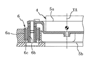
以下に、この発明の実施の形態を実施例によって、図面に基づき詳細に説明する。ここに、図1は、この発明の歩行ロボットの衝撃吸収機構の一実施例を透視状態で、ロボットの他の部分とともに示す斜視図、図2は、その実施例の衝撃吸収機構を具える足部を、ロボットの可動脚および足部関節とともに示す分解斜視図、図3(a),(b)は、上記実施例の衝撃吸収機構を示す平面図および側面図、図4は、図3(b)のA−A線に沿う断面図、図5は、図3(a)のB−B線に沿う断面図、図6は、図3(a)のC−C線に沿う断面図、図7は、上記実施例の衝撃吸収機構の作動状況を示す説明図である。
【0022】
図中符号1は二足歩行ロボット、2はそのロボットの可動脚、3はその可動脚2の脛部、4はその脛部の先端(下端)に設けられた足部関節、5はその足部関節4に結合されてその足部関節4の作動により脛部3に対しヨー軸YA、ロール軸RAおよびピッチ軸PA周りにそれぞれ回動される足部を示し、4a〜4cはその足部関節4のカバーである。ここにおける足部5は、足部関節4に結合された上部基板5aと、上部基板5aの下側にてその上部基板5aに対向する下部基板5bと、上部カバー5cと、下部カバー5dとを具えており、上記ヨー軸YAは、上部基板5aの中心を通って上部基板5aに垂直に延在し、上記ロール軸RAおよびピッチ軸PAは、ヨー軸YAに直交して可動脚2の前後方向および左右方向へそれぞれ延在している。
【0023】
かかる足部5に設けられたこの実施例の衝撃吸収機構は、上部基板5aおよび下部基板5bに加えて、それら上部基板5aと下部基板5bとの間に、上部基板5aに対し垂直方向に延在するヨー軸YAの周囲にて周方向に120度ずつ離間して互いに等間隔に、かつヨー軸YAから互いに等距離に配設されて、各々上部基板5aに対する下部基板5bの弾性的変位をヨー軸YAの延在方向に関しては許容する一方そのヨー軸YAに対し直交する上記ロール軸RAおよびピッチ軸PAの延在方向に関しては抑制しつつ、上部基板5aと下部基板5bとを弾性的に結合する、弾性に関し異方性を持った3つの弾性部材6(例えば、NOK株式会社の製品名「ウルトラブッシュ」)を具えている。
【0024】
3つの弾性部材6は各々、図5に示すように各々円筒状の外筒6aおよび内筒6bと、それら外筒6aおよび内筒6bの間に介挿されてそれらに加硫接着された円筒状のゴム状弾性体6cとを互いに同心に有していわゆるラバーマウント状をなしていて、径方向に硬く、軸方向および捩じり方向には柔らかいものとなっている。ここでは外筒6aが下部基板5bに嵌着固定されるとともに、内筒6bが上部基板5aにボルト固定されている。
【0025】
さらにこの実施例の衝撃吸収機構は、図6に示すように、上部基板5aと下部基板5bとの間に、ヨー軸YAの周囲にて周方向に互いに120度ずつ離間して等間隔に、かつヨー軸YAから互いに等距離に配設されて弾性部材6と隣り合い、上部基板5aに対する下部基板5bの振動を減衰させる3つの高減衰部材7(例えば、NOK株式会社の製品名「ハイダンピングラバー」)を具えており、3つの高減衰部材7は各々、下方にネジ軸が突出した円盤状の座板7aと、その座板7a上に加硫接着された円柱状のゴム状弾性体7bとを有し、この高減衰部材7のゴム状弾性体7bは、弾性部材6のゴム状弾性体6cよりも低い弾性率と高い粘弾性とを持っており、ここでは座板7aが下部基板5bに螺着固定されるとともに、ゴム状弾性体7bが上部基板5aにボルト固定されている。
【0026】
この実施例の衝撃吸収機構によれば、足部5に係るヨー軸YA、ロール軸RAおよびピッチ軸PAの各軸の延在方向の力成分及びそれら軸周りのモーメントの偏差を一定に保つことができ、具体的には、足部5における、足裏に相当する下部基板5bと上部基板5aとの間に配置された弾性部材6により、これらの基板間5a,5bの相対的な変位に係る回転バネ定数を一定としつつ、これらの基板間5a,5bの相対的な位置関係を維持させる変位に等方性を持たせることができるので、歩行制御に係るCPUの演算を簡略化することができる。
【0027】
すなわち、この実施例では、ヨー軸YAの周囲にて周方向に互いに等間隔に3つの弾性部材6を配置したので、上部基板5aに対する下部基板5bのヨー軸YAの延在方向の弾性的変位は許容しつつ、上部基板5aに対する下部基板5bのヨー軸YAに直交する軸線周りの回転を、そのヨー軸YAに直交するとともに互いに直交するロール軸RAおよびピッチ軸PAに対して同等に規制することができる。
【0028】
また、従来の足部の下部基板と上部基板との間の衝撃吸収機構に不可欠であったプレート等の剛性部材を用いたガイド機構を用いず、弾性部材6および高減衰部材7のみの構成とすることができるため、非常に簡易な構成によって歩行制御に好適な衝撃吸収機構を実現することができ、これにより、剛性部材の物理的な干渉による摩擦抵抗による外乱や六軸力センサの破損等を防ぐことができる。
【0029】
さらに、剛性部材を用いたガイド機構を必要としないので足部5の重量が軽減されることになり、可動脚2の振り出しにかかる慣性モーメントを低減することができるため、可動脚2の各関節にかかる負荷を低減し得て、歩行ロボット1の歩行速度の向上や迅速な姿勢維持/回復等をもたらすことができる。
【0030】
さらに、上部基板5aと下部基板5bとの間に、ヨー軸YAの周囲にて周方向に互いに等間隔に配設されて上部基板5aに対する下部基板5bの振動を減衰させる3つの高減衰部材7を具えているため、足部5の衝撃吸収機構に起因する振動を短期間で効果的に減衰することができるので、歩行制御に不適切な振動を抑えることができる。
【0031】
以上、図示例に基づき説明したが、この発明は上述の例に限定されるものでなく、例えば、特許請求の範囲の記載の範囲内で、弾性部材6や高減衰部材7の構成や数を変更することもできる。
【図面の簡単な説明】
【図1】 この発明の歩行ロボットの衝撃吸収機構の一実施例を透視状態で、ロボットの他の部分とともに示す斜視図である。
【図2】 上記実施例の衝撃吸収機構を具える足部を、ロボットの可動脚および足部関節とともに示す分解斜視図である。
【図3】 (a),(b)は、上記実施例の衝撃吸収機構を示す平面図および側面図である。
【図4】 図3(b)のA−A線に沿う断面図である。
【図5】 図3(a)のB−B線に沿う断面図である。
【図6】 図3(a)のC−C線に沿う断面図である。
【図7】 上記実施例の衝撃吸収機構の作動状況を示す説明図である。
【符号の説明】
1 二足歩行ロボット
2 可動脚
3 脛部
4 足部関節
5 足部
5a 上部基板
5b 下部基板
6 弾性部材
7 高減衰部材
YA ヨー軸
RA ロール軸
PA ピッチ軸[0001]
BACKGROUND OF THE INVENTION
The present invention relates to an impact absorbing mechanism for improving the stability of compliance control used for posture control of a walking robot.
[0002]
[Background Art and Problems to be Solved by the Invention]
Conventionally, when walking a walking robot having a plurality of movable legs, the leg link mechanism or the built-in leg link mechanism is caused by a grounding impact when the leg link mechanism collides with an external environment such as the ground or the floor. In order to prevent such a problem that precision devices such as sensors are damaged, an impact absorbing mechanism using, for example, a low-rigidity rubber bush or the like is installed to absorb the impact. There are things in the department.
[0003]
By the way, at the tip foot of the movable leg, the lower substrate corresponding to the sole, which has a contact surface with the ground or the floor, and the upper robot structure including the movable leg coupled to the foot joint are supported. A six-axis force sensor used for compliance control related to the foot joint in biped walking control, especially for walking control of a walking robot having a movable leg is attached between the upper substrate and the upper substrate. is there.
[0004]
In the compliance control of the ankle joint in the walking control of the biped walking robot, the above six-axis force sensor mainly applies the reaction force from the lower substrate due to contact with the ground etc. to the yaw axis direction (vertical direction), roll axis direction (front and back) Direction) and pitch axis direction (left and right direction) force components and moment components around those axes, and based on these parameters, the CPU (central processing unit) built in the robot body performs calculations. Controls the joints of the movable leg.
[0005]
At this time, in a foot mechanism including an elastic member constituting an impact absorbing mechanism such as a rubber bush, the force component measured by the six-axis force sensor and the moment about the axis are in the yaw axis, roll axis, and pitch axis. Each axis has a deviation due to the elastic displacement of the elastic member, which complicates the calculation performed by the CPU built in the robot body for walking control.
[0006]
Maintaining a constant deviation of the force component in each axial direction and the moment around the axis leads to simplification of walking control. For that purpose, specifically, the lower substrate and the upper substrate of the foot structure In the elastic displacement of the elastic member for the purpose of shock absorption interposed between the two, the rotational spring constant related to the displacement between the substrates is constant, and the displacement is isotropic to maintain the relative positional relationship between the substrates It is desirable to have sex.
[0007]
More specifically, the low rigidity elastic displacement by the shock absorbing mechanism such as a rubber bush has low rigidity in the vertical direction (yaw axis direction) to absorb the reaction force from the lower substrate and the load including the robot's own weight from the upper substrate. A structure that restricts displacement (displacement) in the axial direction inappropriate for walking control between the lower substrate and the upper substrate by allowing the elastic displacement and having high rigidity in the axial direction orthogonal to the vertical direction. It is desirable.
[0008]
However, in a walking robot having a movable leg, when the lower substrate comes into contact with the ground or the like in an inclined or uneven terrain state, the elastic member such as a rubber bush constituting the shock absorbing mechanism varies in the displacement amount in each axial direction. Since a certain non-uniform elastic displacement occurs, the rotational spring constant related to the elastic displacement is not constant, and isotropic cannot be obtained for the displacement that maintains the relative positional relationship between the substrates.
[0009]
In addition, when walking a walking robot with a movable leg, especially a biped robot, the swinging leg (moving leg that is not grounded) swings out the supporting leg (which is in a grounded state and loads including its own weight). Since the torque (rotational moment) around the yaw axis is generated in the supporting leg), a large spin force around the yaw axis with the supporting leg as the center of rotation acts. In the elastic member, elastic displacement due to torsion mainly occurs around the yaw axis, and also about the roll axis (around the front-rear axis) and the pitch axis (around the left-right axis) orthogonal to the yaw axis direction. This will cause non-uniform elastic displacement with variations in the amount of displacement, making it impossible to obtain isotropy for the displacement that maintains the relative positional relationship between the substrates, making walking control complicated. I had to.
[0010]
In order to make the relative displacement between the lower substrate and the upper substrate corresponding to the soles isotropic by restricting the non-uniform elastic displacement of the elastic member having such variation in the amount of displacement. Conventionally, a guide mechanism using a rigid member such as a plate having high rigidity in the axial direction orthogonal to the yaw axis direction while allowing elastic displacement of the elastic member in the yaw axis direction can be provided. This is indispensable, and this restricts an axial displacement (displacement) between the lower substrate and the upper substrate that is inappropriate for walking control (see, for example, Patent Document 1).
[0011]
[Patent Document 1]
Japanese Patent Laid-Open No. 11-033941 (paragraph number [0029], FIG. 1)
[0012]
However, attaching a guide mechanism using a rigid member in this way leads to an increase in the weight of the foot mechanism, which increases the moment of inertia that should be suppressed in the movable leg of the walking robot. There has been a problem that frictional resistance is generated by contact with the elastic member, and this frictional resistance acts as a disturbance to walking control.
[0013]
In addition, the foot mechanism is complicated by the addition of a guide mechanism using a rigid member, and depending on the state of walking posture, the rigid member becomes a six-axis force sensor as the elastic member such as a rubber bush is displaced. There was also a problem that the force sensor was damaged due to physical interference.
[0014]
Furthermore, in the compliance control, the six-axis force sensor mainly measures the reaction force from the lower substrate due to contact with the ground or the like. At this time, for example, rubber that absorbs the contact impact between the lower substrate and the ground or the like. An impact absorbing mechanism such as a bush absorbs the contact impact, so it is suitable for protecting the joint structure of a robot including a sensor device such as a six-axis force sensor and a leg link mechanism. Vibration occurs due to the displacement, and vibration remains during the vibration attenuation period, which causes improper vibration to the six-axis force sensor. There was also a problem of acting as a disturbance to control.
[0015]
[Means for solving the problems and their functions and effects]
An object of the present invention is to provide a mechanism that advantageously solves the above problems, and the impact absorbing mechanism of the walking robot according to the present invention includes the movable legs of the walking robot having a plurality of movable legs. In the shock absorbing mechanism provided at the foot portion of the top of the base plate, an upper substrate coupled to the foot joint of the movable leg, a lower substrate facing the upper substrate below the upper substrate, and the upper substrate Between the upper substrate and the lower substrate , arranged around the predetermined axis extending in a direction perpendicular to the upper substrate at equal intervals in the circumferential direction and at equal distance from the predetermined axis , respectively. The upper substrate and the lower substrate have anisotropy in elasticity so as to allow elastic displacement of the lower substrate with respect to the substrate with respect to the extending direction of the predetermined axis while suppressing with respect to a direction orthogonal to the predetermined axis. Base DOO comprising at least three elastic members for elastically coupling, the a, the elastic member are each interposed between the inner cylinder as well as their outer cylinder and the extending direction in each cylindrical extending in the predetermined axis the is a cylindrical rubber-like elastic body has no rubber mount-like structure closed concentric, rigid in the radial direction, is characterized in that there is a soft object in the axial direction and the torsional direction.
[0016]
With this configuration, the force component in each axial direction related to the foot and the deviation of the moment around the axis can be kept constant. Specifically, in the foot, the lower substrate and the upper substrate corresponding to the sole Ri by the rubber mount-like elastic member disposed between, while the rotational spring constant of the relative displacement between the substrates constant, the displacement to maintain the relative positional relationship between the substrates Since it is possible to have isotropic properties, it is possible to simplify the calculation of the CPU related to walking control.
[0017]
Here, if only the rotation around the predetermined axis (yaw axis) extending in the vertical direction with respect to the upper substrate is restricted, it is sufficient to dispose two elastic members between the lower substrate and the upper substrate. When two elastic members are used, rotation around one of the two axes (roll axis, pitch axis) that is orthogonal to the predetermined axis (yaw axis) and orthogonal to each other cannot be restricted. On the other hand, in the present invention, at least three elastic members are arranged at equal intervals in the circumferential direction around the predetermined axis (yaw axis) and at equal distances from the predetermined axis. While allowing the elastic displacement in the extending direction of the predetermined axis (yaw axis), the rotation of the lower substrate around the axis perpendicular to the predetermined axis (yaw axis) relative to the upper substrate is orthogonal to the predetermined axis (yaw axis) In addition, it can be equally regulated with respect to two axes (roll axis and pitch axis) orthogonal to each other.
[0018]
In addition, a rubber mount-like elastic member only is used without using a guide mechanism using a rigid member such as a plate, which has been indispensable for the shock absorbing mechanism between the lower substrate and the upper substrate of the conventional foot. Therefore, a shock absorbing mechanism suitable for walking control can be realized with a very simple configuration, thereby preventing disturbance due to frictional resistance due to physical interference of rigid members, damage to the six-axis force sensor, and the like. be able to.
[0019]
Furthermore, since a guide mechanism using a rigid member is not required, the weight of the foot portion is reduced, and the moment of inertia applied to swinging the movable leg can be reduced, so that the load applied to each joint of the movable leg is reduced. Can be reduced, and the walking speed of the walking robot can be improved and the posture can be maintained / recovered quickly.
[0020]
In the shock absorbing mechanism of the walking robot of the present invention, each have the elastic rubber-like elastic lower modulus than body and high and viscoelasticity one lifting rubber-like elastic body member, the said upper substrate lower Between the substrate and the substrate, and are arranged at equal intervals in the circumferential direction around the predetermined axis and at an equal distance from the predetermined axis to attenuate vibrations of the lower substrate relative to the upper substrate. A damping member may be provided, and in this way, vibration caused by the shock absorbing mechanism of the foot can be effectively attenuated in a short period of time, so that vibration inappropriate for walking control can be suppressed. it can.
[0021]
DETAILED DESCRIPTION OF THE INVENTION
Hereinafter, embodiments of the present invention will be described in detail with reference to the drawings. FIG. 1 is a perspective view showing an embodiment of an impact absorbing mechanism of a walking robot according to the present invention in a see-through state together with other parts of the robot, and FIG. 2 is a foot having the impact absorbing mechanism of the embodiment. 3 is an exploded perspective view showing the robot together with a movable leg and a foot joint of the robot, FIGS. 3A and 3B are a plan view and a side view showing the shock absorbing mechanism of the above embodiment, and FIG. FIG. 5 is a cross-sectional view taken along the line BB in FIG. 3A; FIG. 6 is a cross-sectional view taken along the line CC in FIG. 3A; FIG. 7 is an explanatory view showing the operating state of the shock absorbing mechanism of the above embodiment.
[0022]
In the figure, reference numeral 1 is a biped walking robot, 2 is a movable leg of the robot, 3 is a shin part of the
[0023]
The shock absorbing mechanism of this embodiment provided on the
[0024]
Each three
[0025]
Further, as shown in FIG. 6, the shock absorbing mechanism of this embodiment is spaced 120 degrees apart from each other in the circumferential direction around the yaw axis YA between the
[0026]
According to the shock absorbing mechanism of this embodiment, the force component in the extending direction of each axis of the yaw axis YA, the roll axis RA and the pitch axis PA related to the
[0027]
That is, in this embodiment, since the three
[0028]
Further, only the
[0029]
Further, since a guide mechanism using a rigid member is not required, the weight of the
[0030]
Further, three high-attenuating
[0031]
Although the present invention has been described based on the illustrated examples, the present invention is not limited to the above-described examples. For example, the configuration and number of the
[Brief description of the drawings]
FIG. 1 is a perspective view showing an embodiment of an impact absorbing mechanism for a walking robot according to the present invention in a see-through state together with other parts of the robot.
FIG. 2 is an exploded perspective view showing a foot including the impact absorbing mechanism of the embodiment together with a movable leg and a foot joint of the robot.
FIGS. 3A and 3B are a plan view and a side view showing an impact absorbing mechanism of the embodiment. FIGS.
4 is a cross-sectional view taken along line AA in FIG.
FIG. 5 is a cross-sectional view taken along line BB in FIG.
6 is a cross-sectional view taken along the line CC of FIG. 3 (a).
FIG. 7 is an explanatory view showing an operating state of the shock absorbing mechanism of the embodiment.
[Explanation of symbols]
DESCRIPTION OF SYMBOLS 1
Claims (1)
前記可動脚の足部関節に結合された上部基板と、
前記上部基板の下側にてその上部基板に対向する下部基板と、
前記上部基板と前記下部基板との間に、前記上部基板に対し垂直方向に延在する所定軸線の周囲にて周方向に互いに等間隔にかつ前記所定軸線から互いに等距離に配設されて、各々前記上部基板に対する前記下部基板の弾性的変位を前記所定軸線の延在方向に関しては許容する一方前記所定軸線に対し直交する方向に関しては抑制するように弾性に関し異方性を持って前記上部基板と前記下部基板とを弾性的に結合する少なくとも3つの弾性部材と、
を具え、
前記弾性部材が各々、前記所定軸線の延在方向に延在する各々円筒状の外筒および内筒並びにそれらの間に介挿された円筒状のゴム状弾性体を同心に有するラバーマウント状構造をなしていて、径方向に硬く、軸方向および捩じり方向には柔らかいものとされていることを特徴とする、歩行ロボットの衝撃吸収機構。In the shock absorbing mechanism provided at the foot of the tip of each movable leg of a walking robot having a plurality of movable legs,
An upper substrate coupled to a foot joint of the movable leg;
A lower substrate facing the upper substrate below the upper substrate;
Between the upper substrate and the lower substrate, disposed around the predetermined axis extending in a direction perpendicular to the upper substrate at equal intervals in the circumferential direction and equidistant from the predetermined axis, Each of the upper substrates has anisotropy with respect to elasticity so as to allow elastic displacement of the lower substrate with respect to the upper substrate with respect to the extending direction of the predetermined axis while suppressing with respect to a direction orthogonal to the predetermined axis. And at least three elastic members for elastically coupling the lower substrate and
With
A rubber mount-like structure in which the elastic members each have a cylindrical outer cylinder and an inner cylinder extending in the extending direction of the predetermined axis, and a cylindrical rubber-like elastic body interposed therebetween. A shock absorbing mechanism for a walking robot, characterized in that it is hard in the radial direction and soft in the axial direction and torsional direction.
Priority Applications (7)
| Application Number | Priority Date | Filing Date | Title |
|---|---|---|---|
| JP2002268966A JP4049644B2 (en) | 2002-09-13 | 2002-09-13 | Shock absorption mechanism of walking robot |
| PCT/JP2003/011586 WO2004024400A1 (en) | 2002-09-13 | 2003-09-10 | Impact absorbing mechanism of walking robot |
| EP03795378A EP1550533B1 (en) | 2002-09-13 | 2003-09-10 | Impact absorbing mechanism of walking robot |
| AU2003262061A AU2003262061A1 (en) | 2002-09-13 | 2003-09-10 | Impact absorbing mechanism of walking robot |
| KR1020057004310A KR101004980B1 (en) | 2002-09-13 | 2003-09-10 | Impact absorbing mechanism of walking robot |
| US10/527,728 US7525275B2 (en) | 2002-09-13 | 2003-09-10 | Impact absorbing mechanism of walking robot |
| DE60333659T DE60333659D1 (en) | 2002-09-13 | 2003-09-10 |
Applications Claiming Priority (1)
| Application Number | Priority Date | Filing Date | Title |
|---|---|---|---|
| JP2002268966A JP4049644B2 (en) | 2002-09-13 | 2002-09-13 | Shock absorption mechanism of walking robot |
Publications (2)
| Publication Number | Publication Date |
|---|---|
| JP2004106077A JP2004106077A (en) | 2004-04-08 |
| JP4049644B2 true JP4049644B2 (en) | 2008-02-20 |
Family
ID=31986799
Family Applications (1)
| Application Number | Title | Priority Date | Filing Date |
|---|---|---|---|
| JP2002268966A Expired - Lifetime JP4049644B2 (en) | 2002-09-13 | 2002-09-13 | Shock absorption mechanism of walking robot |
Country Status (7)
| Country | Link |
|---|---|
| US (1) | US7525275B2 (en) |
| EP (1) | EP1550533B1 (en) |
| JP (1) | JP4049644B2 (en) |
| KR (1) | KR101004980B1 (en) |
| AU (1) | AU2003262061A1 (en) |
| DE (1) | DE60333659D1 (en) |
| WO (1) | WO2004024400A1 (en) |
Families Citing this family (5)
| Publication number | Priority date | Publication date | Assignee | Title |
|---|---|---|---|---|
| JP5171290B2 (en) * | 2007-02-02 | 2013-03-27 | 本田技研工業株式会社 | Legged mobile robot |
| US7905303B2 (en) * | 2009-02-10 | 2011-03-15 | Honda Motor Co., Ltd. | Legged locomotion robot |
| CN101823517B (en) * | 2010-05-11 | 2011-09-28 | 浙江大学 | Flexible foot mechanism of humanoid robot |
| JP6179349B2 (en) * | 2013-10-28 | 2017-08-16 | セイコーエプソン株式会社 | SCARA robot |
| CN108068908B (en) * | 2017-12-29 | 2023-10-10 | 深圳市优必选科技有限公司 | Robot foot plate structure and humanoid robot |
Family Cites Families (19)
| Publication number | Priority date | Publication date | Assignee | Title |
|---|---|---|---|---|
| JPS5824291B2 (en) | 1979-11-01 | 1983-05-20 | マツダ株式会社 | Differential gear case support device for rear wheel drive vehicles |
| US5255753A (en) * | 1989-12-14 | 1993-10-26 | Honda Giken Kogyo Kabushiki Kaisha | Foot structure for legged walking robot |
| JPH04175527A (en) * | 1990-11-06 | 1992-06-23 | Bando Chem Ind Ltd | Press-fitting type rubber bush |
| JP3167404B2 (en) * | 1992-02-26 | 2001-05-21 | 本田技研工業株式会社 | Robot joint drive controller |
| US5455497A (en) * | 1992-04-20 | 1995-10-03 | Honda Giken Kogyo Kabushiki Kaisha | Legged mobile robot and a system for controlling the same |
| JP3118777B2 (en) * | 1992-04-20 | 2000-12-18 | 本田技研工業株式会社 | Leg structure of a legged walking robot |
| US5416393A (en) * | 1992-05-20 | 1995-05-16 | Honda Giken Kogyo Kabushiki Kaisha | Legged mobile robot foot structure |
| US5445497A (en) * | 1993-12-27 | 1995-08-29 | Seemar; George H. | Variable pitch propellers |
| JP3649865B2 (en) | 1997-07-23 | 2005-05-18 | 本田技研工業株式会社 | Leg structure of legged mobile robot |
| EP1048563A3 (en) * | 1999-04-30 | 2001-04-11 | Lord Corporation | Self-centering bearing for aircraft control surfaces |
| JP4213310B2 (en) * | 1999-08-30 | 2009-01-21 | 本田技研工業株式会社 | Biped legged mobile robot |
| JP4279425B2 (en) * | 1999-11-05 | 2009-06-17 | 本田技研工業株式会社 | Foot structure of legged walking robot |
| TW499349B (en) * | 2000-11-17 | 2002-08-21 | Sony Corp | Legged mobile robot, leg structure of legged mobile robot, and mobile leg unit for legged mobile robot |
| JP3672867B2 (en) * | 2001-12-25 | 2005-07-20 | 本田技研工業株式会社 | Landing shock absorber for legged mobile robot |
| JP3726057B2 (en) * | 2001-12-28 | 2005-12-14 | 本田技研工業株式会社 | Legged mobile robot and its floor reaction force detection device |
| JP4109456B2 (en) * | 2002-01-18 | 2008-07-02 | 独立行政法人産業技術総合研究所 | Low rigidity force detector |
| KR100571839B1 (en) * | 2004-03-31 | 2006-04-17 | 삼성전자주식회사 | Anthropomorphic robot |
| JP4495549B2 (en) * | 2004-08-30 | 2010-07-07 | 本田技研工業株式会社 | Legged mobile robot |
| JP4504768B2 (en) * | 2004-09-17 | 2010-07-14 | 本田技研工業株式会社 | Legged mobile robot |
-
2002
- 2002-09-13 JP JP2002268966A patent/JP4049644B2/en not_active Expired - Lifetime
-
2003
- 2003-09-10 WO PCT/JP2003/011586 patent/WO2004024400A1/en active Application Filing
- 2003-09-10 KR KR1020057004310A patent/KR101004980B1/en active IP Right Grant
- 2003-09-10 DE DE60333659T patent/DE60333659D1/de not_active Expired - Lifetime
- 2003-09-10 EP EP03795378A patent/EP1550533B1/en not_active Expired - Lifetime
- 2003-09-10 US US10/527,728 patent/US7525275B2/en active Active
- 2003-09-10 AU AU2003262061A patent/AU2003262061A1/en not_active Abandoned
Also Published As
| Publication number | Publication date |
|---|---|
| KR101004980B1 (en) | 2011-01-04 |
| EP1550533A4 (en) | 2007-12-12 |
| KR20050063766A (en) | 2005-06-28 |
| WO2004024400A1 (en) | 2004-03-25 |
| EP1550533A1 (en) | 2005-07-06 |
| EP1550533B1 (en) | 2010-08-04 |
| AU2003262061A1 (en) | 2004-04-30 |
| US20060237241A1 (en) | 2006-10-26 |
| US7525275B2 (en) | 2009-04-28 |
| JP2004106077A (en) | 2004-04-08 |
| DE60333659D1 (en) | 2010-09-16 |
Similar Documents
| Publication | Publication Date | Title |
|---|---|---|
| CN100376364C (en) | Foot structure for humanoid robot and robot with the same | |
| US7600591B2 (en) | Leg type mobile robot | |
| US7300387B2 (en) | Treadle assembly of an exercise equipment | |
| US5455497A (en) | Legged mobile robot and a system for controlling the same | |
| US20180162187A1 (en) | Vehicle with suspension force decoupling system | |
| US7904200B2 (en) | Leg type mobile robot | |
| US20090088301A1 (en) | Treadmill with cushion assembly | |
| KR101947803B1 (en) | Stevie Link | |
| WO2003022533A1 (en) | Floor reaction detector of legged mobile robot | |
| JP4049644B2 (en) | Shock absorption mechanism of walking robot | |
| JP4109456B2 (en) | Low rigidity force detector | |
| CN210761039U (en) | Multi-degree-of-freedom foot device with single driving force and capable of adapting to terrain | |
| CN221273292U (en) | Mechanical bionic foot | |
| CN114435505B (en) | Robot flexible foot | |
| KR20170119350A (en) | Steplink of suspension for vehicle | |
| KR20230112335A (en) | a shock absorber for a vehicle | |
| JPH08113178A (en) | Front wheel shock absorber for bicycle | |
| JP2000225803A (en) | Caster | |
| JP2010133495A (en) | Shock absorbing mechanism | |
| KR101284874B1 (en) | Bush and mounting unit using the same | |
| KR20030014434A (en) | Pillow ball bush | |
| KR20020039729A (en) | An automotive suspension for removing torsional force |
Legal Events
| Date | Code | Title | Description |
|---|---|---|---|
| A131 | Notification of reasons for refusal |
Free format text: JAPANESE INTERMEDIATE CODE: A131 Effective date: 20050301 |
|
| A521 | Request for written amendment filed |
Free format text: JAPANESE INTERMEDIATE CODE: A523 Effective date: 20050428 |
|
| A131 | Notification of reasons for refusal |
Free format text: JAPANESE INTERMEDIATE CODE: A131 Effective date: 20051025 |
|
| A521 | Request for written amendment filed |
Free format text: JAPANESE INTERMEDIATE CODE: A523 Effective date: 20051226 |
|
| A02 | Decision of refusal |
Free format text: JAPANESE INTERMEDIATE CODE: A02 Effective date: 20060620 |
|
| A521 | Request for written amendment filed |
Free format text: JAPANESE INTERMEDIATE CODE: A523 Effective date: 20060821 |
|
| A911 | Transfer to examiner for re-examination before appeal (zenchi) |
Free format text: JAPANESE INTERMEDIATE CODE: A911 Effective date: 20060828 |
|
| A912 | Re-examination (zenchi) completed and case transferred to appeal board |
Free format text: JAPANESE INTERMEDIATE CODE: A912 Effective date: 20060922 |
|
| A61 | First payment of annual fees (during grant procedure) |
Free format text: JAPANESE INTERMEDIATE CODE: A61 Effective date: 20071127 |
|
| R150 | Certificate of patent or registration of utility model |
Free format text: JAPANESE INTERMEDIATE CODE: R150 Ref document number: 4049644 Country of ref document: JP Free format text: JAPANESE INTERMEDIATE CODE: R150 |
|
| FPAY | Renewal fee payment (event date is renewal date of database) |
Free format text: PAYMENT UNTIL: 20101207 Year of fee payment: 3 |
|
| FPAY | Renewal fee payment (event date is renewal date of database) |
Free format text: PAYMENT UNTIL: 20101207 Year of fee payment: 3 |
|
| FPAY | Renewal fee payment (event date is renewal date of database) |
Free format text: PAYMENT UNTIL: 20111207 Year of fee payment: 4 |
|
| R250 | Receipt of annual fees |
Free format text: JAPANESE INTERMEDIATE CODE: R250 |
|
| FPAY | Renewal fee payment (event date is renewal date of database) |
Free format text: PAYMENT UNTIL: 20111207 Year of fee payment: 4 |
|
| FPAY | Renewal fee payment (event date is renewal date of database) |
Free format text: PAYMENT UNTIL: 20121207 Year of fee payment: 5 |
|
| R250 | Receipt of annual fees |
Free format text: JAPANESE INTERMEDIATE CODE: R250 |
|
| FPAY | Renewal fee payment (event date is renewal date of database) |
Free format text: PAYMENT UNTIL: 20131207 Year of fee payment: 6 |
|
| R250 | Receipt of annual fees |
Free format text: JAPANESE INTERMEDIATE CODE: R250 |
|
| R250 | Receipt of annual fees |
Free format text: JAPANESE INTERMEDIATE CODE: R250 |
|
| R250 | Receipt of annual fees |
Free format text: JAPANESE INTERMEDIATE CODE: R250 |
|
| R250 | Receipt of annual fees |
Free format text: JAPANESE INTERMEDIATE CODE: R250 |
|
| R250 | Receipt of annual fees |
Free format text: JAPANESE INTERMEDIATE CODE: R250 |
|
| R250 | Receipt of annual fees |
Free format text: JAPANESE INTERMEDIATE CODE: R250 |
|
| R250 | Receipt of annual fees |
Free format text: JAPANESE INTERMEDIATE CODE: R250 |
|
| R250 | Receipt of annual fees |
Free format text: JAPANESE INTERMEDIATE CODE: R250 |
|
| R250 | Receipt of annual fees |
Free format text: JAPANESE INTERMEDIATE CODE: R250 |
|
| R250 | Receipt of annual fees |
Free format text: JAPANESE INTERMEDIATE CODE: R250 |
|
| EXPY | Cancellation because of completion of term |