JP4049459B2 - Laser processing method - Google Patents
Laser processing method Download PDFInfo
- Publication number
- JP4049459B2 JP4049459B2 JP28713998A JP28713998A JP4049459B2 JP 4049459 B2 JP4049459 B2 JP 4049459B2 JP 28713998 A JP28713998 A JP 28713998A JP 28713998 A JP28713998 A JP 28713998A JP 4049459 B2 JP4049459 B2 JP 4049459B2
- Authority
- JP
- Japan
- Prior art keywords
- mirror
- angle
- galvano mirror
- galvanometer
- laser
- Prior art date
- Legal status (The legal status is an assumption and is not a legal conclusion. Google has not performed a legal analysis and makes no representation as to the accuracy of the status listed.)
- Expired - Lifetime
Links
Images

Description
【0001】
【発明の属する技術分野】
本発明は、ガルバノメータを用いた高速位置決め制御全般に適用される。特に、ガルバノメータの高速位置決めが必要とされるレーザ穴加工方法に関し、詳しくは、ガルバノメータに取り付けたミラーを介して、回路基板などにレーザを照射し、穴を加工する方法に関するものである。
【0002】
【従来の技術】
高密度配線の回路基板にスルーホール等の穴を加工する作業において、ガルバノミラーを用いたレーザ穴加工技術が採用されている。
【0003】
レーザ穴加工技術は、被加工材にレーザ光線を照射し、レーザ光線のエネルギーで被加工材を溶解あるいは蒸発させて穴を空ける方法であり、ミクロン単位の微細な穴を正確な位置に加工する場合に適している。最近の携帯電話等の電子機器を代表する高密度配線の回路基板における単位面積当たりの穴加工数は、穴の微細化、基板の高密度化により、ますます増加しており、このような回路基板の製造にレーザ穴加工技術が広く利用されるようにするためには、穴加工の高速化が必要不可欠となっている。
【0004】
ガルバノメータにミラーを取り付けてなるガルバノミラーを用いた穴加工技術の具体例としては、本出願人が先に特許出願した特開平8−174256号公報等に開示されているように、レーザ光線をガルバノミラーで反射させ、集光レンズにより集光して、加工対象である回路基板に照射させることで、レーザ加工を行うようになっている。
【0005】
このような穴加工技術に用いられるガルバノメータは、μradオーダーの高分解能を有するとともに、光学角±20°の駆動領域と高速位置決めの特性を有し、微小角が検知可能な静電容量センサを位置検知手段として設けてサーボ系のアナログフィードバック制御にて位置決めを行っている。
【0006】
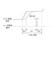
具体的には、ガルバノメータに対する移動の指令が制御部から与えられると、図4に示すように、実際の回転移動角度が目標回転角度を越えないように制御しながら、目標回転角度に徐々に近づくようにガルバノメータを回動制御させ、目標回転角度に達して安定した時点で、レーザ光線の照射指令を発して、レーザ加工を行う。
【0007】
ここで、図4におけるMvはガルバノミラーに対する移動指令として目標回転角度を変動させている移動時間、Jdはその後に目標回転角度までガルバノミラーが移動して位置決めされるまでの位置決め時間、Lonはレーザ光線の照射時間、Sdはレーザ波尾待時間である。
【0008】
なお、ガルバノミラーの位置を検知する静電容量センサは微小なアナログ信号で出力され、ノイズ等の影響等により目標位置決め完了の判定に用いることは難しいので、実際には目標位置決め完了の判定は、フィードバック制御におけるガルバノミラーに対する移動指令の変動が終了した時点(移動時間Mvの終点)から一定の待ち時間を位置決め時間Jdとして設定し、この位置決め時間Jdを経過した時点で位置決めを完了したとみなして判定し、位置決め完了後にレーザ光線の照射を開始している。位置決め時間Jdとしては、ガルバノミラーの回転移動角度が大きくて時間がかかるワーストケースを想定して、長めの時間が設定されている。
【0009】
【発明が解決しようとする課題】
しかしながら、上記のようにガルバノミラーを制御すると、ガルバノミラーの回転移動角度の大きさにかかわらず、常に長めの時間を待ってから位置決めを完了したとみなしているため、ガルバノミラーの位置決めに比較的長い時間がかかってしまい、被加工物の1枚あたりの加工タクトを短くすることができないで処理能力が上がらず、生産性が向上しないという課題を生じていた。
【0010】
本発明は上記課題を解決するもので、被加工物の1枚あたりの加工タクトを短くすることが可能となり、生産性が向上するレーザ加工方法を提供することを目的とするものである。
【0011】
【課題を解決するための手段】
上記課題を解決するために本発明は、移動指令によってガルバノミラーを回転させ、前記ガルバノミラーの回転角度を検出し、前記検出した回転角度と目標回転角度との角度差を検出し、前記検出した角度差に基づいてガルバノミラーを目標回転角度に位置決めし、前記移動指令から前記ガルバノミラーの移動角度に対応した設定待ち時間後に前記ガルバノミラーに対してレーザ光線を照射し、前記ガルバノミラーで反射されたレーザ光線を集光レンズにより集光して被加工物に照射することでレーザ加工を行うレーザ加工方法であって、前記ガルバノミラーの移動角度が小さいほど前記設定待ち時間が少ないことを特徴とするものである。
【0012】
この方法により、被加工物の1枚あたりの加工タクトを短くすることが可能となり、生産性が向上する。
【0013】
【発明の実施の形態】
本発明は、移動指令によってガルバノミラーを回転させ、前記ガルバノミラーの回転角度を検出し、前記検出した回転角度と目標回転角度との角度差を検出し、前記検出した角度差に基づいてガルバノミラーを目標回転角度に位置決めし、前記移動指令から前記ガルバノミラーの移動角度に対応した設定待ち時間後に前記ガルバノミラーに対してレーザ光線を照射し、前記ガルバノミラーで反射されたレーザ光線を集光レンズにより集光して被加工物に照射することでレーザ加工を行うレーザ加工方法であって、前記ガルバノミラーの移動角度が小さいほど前記設定待ち時間が少ないことを特徴とするものである。
【0014】
上記方法によれば、ガルバノミラーの移動角度が小さい場合には設定待ち時間を少なくすることができるため、被加工物の1枚あたりの加工タクトを短くすることが可能となり、生産性が向上する。
【0015】
以下、本発明の実施の形態を図面に基づき説明する。この実施の形態においては、高密度配線の回路基板にスルーホール等の穴を加工するレーザ加工装置に用いられる場合に付いて説明する。
【0016】
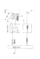
図1に示すように、レーザ加工装置は、レーザ光線1を出射するレーザ発振器2と、レーザ光線1を分岐させるビームスプリッタ3と、ガルバノメータ4aにミラー4bが取り付けられてなるガルバノミラー4と、レーザ光線1を平面上に集光する集光レンズとしてのFθレンズ5と、X軸方向ならびにY軸方向に移動自在とされ、被加工物6としての回路基板を載置するXYテーブル7とにより基本構成されている。
【0017】
そして、XYテーブル7上におかれた被加工物6の任意の位置に穴を空けるために、XYテーブル7が指令位置に位置決めされ、かつガルバノミラー4が指令位置に位置決めされて完了した後に、レーザ発振器2よりレーザ光線1を照射して、穴加工を行うようになっている。ガルバノミラー4の位置決めによって、50mm×50mmエリア内の任意の点に穴加工でき、XYテーブル7は、50mm単位で移動動作して、500mm×350mmの被加工物6における任意の位置を加工できるように構成されている。
【0018】
なお、図1に示すレーザ加工装置においては、レーザ光線をビームスプリッタ3で分岐し、2対のガルバノミラー4およびFθレンズ5を配置して、XYテーブル7上に2対の被加工物6を置くことによって2枚の被加工物6に対する同時加工を実現している。
【0019】
ところで、最近の携帯電話等の電子機器を代表する高密度配線の回路基板は、穴の微細化、回路基板の高密度化により、50mm×50mm当たりの穴加工数は、1000穴、回路基板全体では50000穴を超えており、ガルバノミラー4の位置決めの時間が1枚の被加工物加工タクトに大きく影響する。
【0020】
図2はガルバノミラー4に関する制御系を示す。図2に示すように、位置検知手段としての静電容量センサ9で検出したガルバノミラー4の実際の回転移動角度と、ガルバノミラー4の目標回転角度との差を、角度差検出部として機能するガルバノドライバ8で算出しながら、この差に基づいてフィードバック制御を行ってガルバノミラー4を目標回転角度に近づくように移動させ、制御部としての上位コントローラ10からの移動指令から設定待ち時間後にガルバノミラーの位置決めを完了したとみなし、位置決め完了後にレーザ光線を照射する位置決めしてレーザ光線を照射する。
【0021】
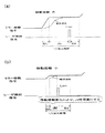
本発明では、この場合に、図3(a),(b)に示すように、ガルバノミラー4の移動角度に応じて記設定待ち時間を設定するものである。具体的には、図3(b)に示すように、ガルバノミラー4の移動角度(移動距離)が小さいほど設定待ち時間である位置決め時間Jdを少なくするように設定する。
【0022】
なお、図3(a),(b)における、Mvはガルバノミラー4に対する移動指令として目標回転角度を変動させている移動時間、Jdはその後に目標回転角度までガルバノミラー4が移動して位置決めされるまでの位置決め時間、Lonはレーザ光線の照射時間、Sdはレーザ波尾待時間である。
【0023】
これにより、従来においては、ガルバノミラー4の移動角度が小さい場合でも、常に長めの時間を待ってから位置決めを完了したとみなしているため、ガルバノミラー4の位置決めに比較的長い時間がかかっていたが、この制御方法によれば、ガルバノミラー4の移動角度が小さい場合には設定待ち時間である位置決め時間Jdを少なくすることができるため、被加工物の1枚あたりの加工タクトを短くすることが可能となり、生産性が向上する。
【0024】
【発明の効果】
以上のように本発明によれば、ガルバノミラーの移動角度が小さい場合には設定待ち時間を少なくすることができるため、時間管理による制御方法でのロス時間がなくなり、被加工物の1枚あたりの加工タクトを短くすることが可能となって、生産性が向上する。
【図面の簡単な説明】
【図1】本発明の実施の形態にかかるレーザ加工方法を行うレーザ加工装置の斜視図
【図2】同レーザ加工装置のガルバノミラー制御系を示す図
【図3】(a),(b)はそれぞれ同レーザ加工方法を概念的に示す図で、(a)はガルバノミラーの移動距離が大きい場合を示し、(b)は移動距離が小さい場合を示す図
【図4】従来のレーザ加工方法を概念的に示す図
【符号の説明】
1 レーザ光線
2 レーザ発振器
4 ガルバノミラー
4a ガルバノメータ
4b ミラー
5 Fθレンズ(集光レンズ)
6 XYテーブル
7 被加工物
8 ガルバノドライバ
9 静電容量センサ(位置検知手段)
10 上位コントローラ(制御部)[0001]
BACKGROUND OF THE INVENTION
The present invention is applied to general high-speed positioning control using a galvanometer. In particular, the present invention relates to a laser hole machining method that requires high-speed positioning of a galvanometer, and more particularly to a method of machining a hole by irradiating a circuit board or the like with a laser via a mirror attached to the galvanometer.
[0002]
[Prior art]
A laser hole machining technique using a galvanometer mirror is adopted in an operation for machining a hole such as a through hole in a circuit board with high-density wiring.
[0003]
Laser drilling technology is a method of irradiating a workpiece with a laser beam and melting or evaporating the workpiece with the energy of the laser beam to form a hole. Suitable for cases. The number of holes processed per unit area in circuit boards with high-density wiring, which is representative of recent electronic devices such as mobile phones, is increasing more and more due to finer holes and higher board density. In order for the laser drilling technology to be widely used in the manufacture of substrates, it is essential to increase the speed of drilling.
[0004]
As a specific example of a hole processing technique using a galvanometer mirror in which a mirror is attached to a galvanometer, a laser beam is galvanometered as disclosed in Japanese Patent Application Laid-Open No. Hei 8-174256 and the like previously filed by the present applicant. Laser processing is performed by reflecting the light with a mirror, condensing with a condensing lens, and irradiating the circuit board to be processed.
[0005]
The galvanometer used in such hole drilling technology has a high resolution on the order of μrad, and has a drive region with an optical angle of ± 20 ° and a high-speed positioning characteristic. Positioning is performed by analog feedback control of the servo system provided as detection means.
[0006]
Specifically, when a movement command for the galvanometer is given from the control unit, as shown in FIG. 4, the actual rotational movement angle is controlled so as not to exceed the target rotational angle, and gradually approaches the target rotational angle. In this way, the galvanometer is controlled to rotate, and when the target rotation angle is reached and stabilized, a laser beam irradiation command is issued to perform laser processing.
[0007]
Here, Mv in FIG. 4 is a movement time in which the target rotation angle is varied as a movement command for the galvanometer mirror, Jd is a positioning time until the galvanometer mirror is subsequently moved to the target rotation angle, and Lon is a laser. The light irradiation time, Sd, is the laser wave tail waiting time.
[0008]
Note that the capacitance sensor that detects the position of the galvanometer mirror is output as a minute analog signal and is difficult to use for determining target positioning completion due to the influence of noise, etc. A fixed waiting time is set as the positioning time Jd from the time when movement of the movement command to the galvano mirror in the feedback control ends (end point of the moving time Mv), and it is considered that the positioning is completed when the positioning time Jd elapses. The laser beam irradiation is started after the determination and the positioning is completed. As the positioning time Jd, a longer time is set assuming a worst case where the rotational movement angle of the galvano mirror is large and takes a long time.
[0009]
[Problems to be solved by the invention]
However, when the galvanometer mirror is controlled as described above, it is considered that the positioning is completed after waiting for a long time regardless of the rotational movement angle of the galvanometer mirror. It takes a long time, and the processing tact per workpiece cannot be shortened, resulting in a problem that the processing capacity does not increase and productivity does not improve.
[0010]
SUMMARY OF THE INVENTION The present invention solves the above-described problems, and an object of the present invention is to provide a laser processing method that can shorten the processing tact per workpiece and improves the productivity.
[0011]
[Means for Solving the Problems]
In order to solve the above-mentioned problem, the present invention rotates a galvano mirror according to a movement command, detects a rotation angle of the galvano mirror, detects an angle difference between the detected rotation angle and a target rotation angle, and detects the detected Based on the angle difference, the galvano mirror is positioned at a target rotation angle, and after a set waiting time corresponding to the movement angle of the galvano mirror from the movement command, the galvano mirror is irradiated with a laser beam and reflected by the galvano mirror. A laser processing method for performing laser processing by condensing the laser beam with a condensing lens and irradiating the workpiece, wherein the setting waiting time is smaller as the movement angle of the galvanometer mirror is smaller. To do.
[0012]
By this method, it is possible to shorten the processing tact per one workpiece, and the productivity is improved.
[0013]
DETAILED DESCRIPTION OF THE INVENTION
The present invention rotates a galvano mirror according to a movement command, detects a rotation angle of the galvano mirror, detects an angle difference between the detected rotation angle and a target rotation angle, and based on the detected angle difference, the galvano mirror Is positioned at a target rotation angle, and after a set waiting time corresponding to the movement angle of the galvano mirror from the movement command, the galvano mirror is irradiated with a laser beam, and the laser beam reflected by the galvano mirror is reflected on the condenser lens. Is a laser processing method for performing laser processing by condensing and irradiating a workpiece, and the smaller the movement angle of the galvanometer mirror, the shorter the set waiting time .
[0014]
According to the above method, since the set waiting time can be reduced when the movement angle of the galvano mirror is small, the machining tact per workpiece can be shortened, and the productivity is improved. .
[0015]
Hereinafter, embodiments of the present invention will be described with reference to the drawings. In this embodiment, a case where the present invention is used in a laser processing apparatus that processes holes such as through holes in a circuit board having high-density wiring will be described.
[0016]
As shown in FIG. 1, the laser processing apparatus includes a
[0017]
After the XY table 7 is positioned at the command position and the
[0018]
In the laser processing apparatus shown in FIG. 1, the laser beam is split by the
[0019]
By the way, circuit boards with high-density wiring, which are representative of recent electronic devices such as mobile phones, have 1000 holes per 50 mm × 50 mm due to finer holes and higher circuit board density. In this case, the number of holes exceeds 50,000 holes, and the positioning time of the
[0020]
FIG. 2 shows a control system related to the
[0021]
In this case, according to the present invention, the set waiting time is set according to the movement angle of the
[0022]
In FIGS. 3A and 3B, Mv is a movement time during which the target rotation angle is changed as a movement command for the
[0023]
As a result, in the prior art, even when the movement angle of the
[0024]
【The invention's effect】
As described above, according to the present invention, when the moving angle of the galvano mirror is small, the set waiting time can be reduced, so that the loss time in the control method based on time management is eliminated, and one workpiece is processed. This makes it possible to shorten the machining tact time and improve productivity.
[Brief description of the drawings]
FIG. 1 is a perspective view of a laser processing apparatus for performing a laser processing method according to an embodiment of the present invention. FIG. 2 is a diagram showing a galvanomirror control system of the laser processing apparatus. 4A and 4B are diagrams conceptually showing the laser processing method, wherein FIG. 4A shows a case where the moving distance of the galvano mirror is large, and FIG. 4B shows a case where the moving distance is small. Diagram conceptually [Explanation of symbols]
DESCRIPTION OF SYMBOLS 1
6 XY table 7 Work piece 8 Galvano driver 9 Capacitance sensor (position detection means)
10 Host controller (control unit)
Claims (1)
Priority Applications (1)
| Application Number | Priority Date | Filing Date | Title |
|---|---|---|---|
| JP28713998A JP4049459B2 (en) | 1998-10-09 | 1998-10-09 | Laser processing method |
Applications Claiming Priority (1)
| Application Number | Priority Date | Filing Date | Title |
|---|---|---|---|
| JP28713998A JP4049459B2 (en) | 1998-10-09 | 1998-10-09 | Laser processing method |
Publications (3)
| Publication Number | Publication Date |
|---|---|
| JP2000117476A JP2000117476A (en) | 2000-04-25 |
| JP2000117476A5 JP2000117476A5 (en) | 2005-07-21 |
| JP4049459B2 true JP4049459B2 (en) | 2008-02-20 |
Family
ID=17713583
Family Applications (1)
| Application Number | Title | Priority Date | Filing Date |
|---|---|---|---|
| JP28713998A Expired - Lifetime JP4049459B2 (en) | 1998-10-09 | 1998-10-09 | Laser processing method |
Country Status (1)
| Country | Link |
|---|---|
| JP (1) | JP4049459B2 (en) |
Families Citing this family (7)
| Publication number | Priority date | Publication date | Assignee | Title |
|---|---|---|---|---|
| JP3407715B2 (en) * | 2000-06-06 | 2003-05-19 | 松下電器産業株式会社 | Laser processing equipment |
| JP4698092B2 (en) * | 2001-07-11 | 2011-06-08 | 住友重機械工業株式会社 | Galvano scanner device and control method thereof |
| JP4630853B2 (en) * | 2006-03-30 | 2011-02-09 | 日立ビアメカニクス株式会社 | Positioning control device for moving body and laser processing device |
| JP5167187B2 (en) * | 2009-03-31 | 2013-03-21 | 日立ビアメカニクス株式会社 | Laser drilling method |
| JP5393598B2 (en) * | 2010-06-03 | 2014-01-22 | キヤノン株式会社 | Galvano device and laser processing device |
| JP5724982B2 (en) * | 2012-09-27 | 2015-05-27 | ブラザー工業株式会社 | 2-axis galvanometer mirror device |
| JP6431333B2 (en) * | 2014-10-15 | 2018-11-28 | キヤノン株式会社 | Processing equipment |
-
1998
- 1998-10-09 JP JP28713998A patent/JP4049459B2/en not_active Expired - Lifetime
Also Published As
| Publication number | Publication date |
|---|---|
| JP2000117476A (en) | 2000-04-25 |
Similar Documents
| Publication | Publication Date | Title |
|---|---|---|
| US5126532A (en) | Apparatus and method of boring using laser | |
| US5166493A (en) | Apparatus and method of boring using laser | |
| JP5025158B2 (en) | Laser processing method and apparatus | |
| JPH10323785A (en) | Laser processing device | |
| JP2002542043A (en) | Material processing system and method using multiple laser beams | |
| JP3769942B2 (en) | Laser processing method and apparatus, and circuit forming method and apparatus for non-conductive transparent substrate | |
| JP4049459B2 (en) | Laser processing method | |
| KR0141060B1 (en) | Co2 laser processing apparatus | |
| JP3614308B2 (en) | Laser processing method | |
| JP3323987B2 (en) | Laser processing equipment | |
| JP2001096381A (en) | Laser beam machining process | |
| JP3177023B2 (en) | Method and apparatus for processing external shape of flexible wiring board | |
| JP2005262219A (en) | Laser beam machining apparatus and laser beam drawing method | |
| JPH09308983A (en) | Laser beam machine | |
| JP2002346775A (en) | Device and method for laser beam machining | |
| JP2003080386A (en) | Laser machining device | |
| JPH03142087A (en) | Method for boring printed wiring board | |
| JP2001079678A (en) | Method for laser piercing and device therefor | |
| JP2001068817A (en) | Forming method of microwave circuit | |
| JP2000263840A (en) | Laser printing method and laser printing apparatus | |
| JP4698092B2 (en) | Galvano scanner device and control method thereof | |
| JP2002318361A (en) | Control method for positioning galvanometer | |
| JP3341114B2 (en) | Laser processing apparatus and laser processing method | |
| CN112496570B (en) | Processing method and device for ultrafast ultraviolet laser PCB material | |
| JP3312294B2 (en) | Laser processing apparatus and laser processing method using multi-axis galvano scanner |
Legal Events
| Date | Code | Title | Description |
|---|---|---|---|
| A521 | Written amendment |
Free format text: JAPANESE INTERMEDIATE CODE: A523 Effective date: 20041208 |
|
| A621 | Written request for application examination |
Free format text: JAPANESE INTERMEDIATE CODE: A621 Effective date: 20041208 |
|
| A977 | Report on retrieval |
Free format text: JAPANESE INTERMEDIATE CODE: A971007 Effective date: 20070518 |
|
| A131 | Notification of reasons for refusal |
Free format text: JAPANESE INTERMEDIATE CODE: A131 Effective date: 20070529 |
|
| A521 | Written amendment |
Free format text: JAPANESE INTERMEDIATE CODE: A523 Effective date: 20070702 |
|
| A521 | Written amendment |
Free format text: JAPANESE INTERMEDIATE CODE: A523 Effective date: 20070725 |
|
| TRDD | Decision of grant or rejection written | ||
| A01 | Written decision to grant a patent or to grant a registration (utility model) |
Free format text: JAPANESE INTERMEDIATE CODE: A01 Effective date: 20071030 |
|
| A61 | First payment of annual fees (during grant procedure) |
Free format text: JAPANESE INTERMEDIATE CODE: A61 Effective date: 20071127 |
|
| FPAY | Renewal fee payment (event date is renewal date of database) |
Free format text: PAYMENT UNTIL: 20101207 Year of fee payment: 3 |
|
| FPAY | Renewal fee payment (event date is renewal date of database) |
Free format text: PAYMENT UNTIL: 20101207 Year of fee payment: 3 |
|
| FPAY | Renewal fee payment (event date is renewal date of database) |
Free format text: PAYMENT UNTIL: 20111207 Year of fee payment: 4 |
|
| FPAY | Renewal fee payment (event date is renewal date of database) |
Free format text: PAYMENT UNTIL: 20111207 Year of fee payment: 4 |
|
| FPAY | Renewal fee payment (event date is renewal date of database) |
Free format text: PAYMENT UNTIL: 20121207 Year of fee payment: 5 |
|
| FPAY | Renewal fee payment (event date is renewal date of database) |
Free format text: PAYMENT UNTIL: 20121207 Year of fee payment: 5 |
|
| FPAY | Renewal fee payment (event date is renewal date of database) |
Free format text: PAYMENT UNTIL: 20131207 Year of fee payment: 6 |
|
| EXPY | Cancellation because of completion of term |