JP4046898B2 - Manufacturing method of insert molded product - Google Patents
Manufacturing method of insert molded product Download PDFInfo
- Publication number
- JP4046898B2 JP4046898B2 JP18825199A JP18825199A JP4046898B2 JP 4046898 B2 JP4046898 B2 JP 4046898B2 JP 18825199 A JP18825199 A JP 18825199A JP 18825199 A JP18825199 A JP 18825199A JP 4046898 B2 JP4046898 B2 JP 4046898B2
- Authority
- JP
- Japan
- Prior art keywords
- insert
- molded product
- mold
- resin
- holding
- Prior art date
- Legal status (The legal status is an assumption and is not a legal conclusion. Google has not performed a legal analysis and makes no representation as to the accuracy of the status listed.)
- Expired - Fee Related
Links
Images

Landscapes
- Manufacturing Of Electrical Connectors (AREA)
- Moulds For Moulding Plastics Or The Like (AREA)
- Injection Moulding Of Plastics Or The Like (AREA)
Description
【0001】
【発明の属する技術分野】
本発明は、複数のインサートを有するインサート成形品の製造方法に関する。詳しくは、複数のインサートと、接合部を介して相隣るインサートを接合する保持部からなるインサート整列体を使用し、樹脂を注入してインサート成形し、成形後に保持部を取り除くことによるインサート成形品の製造方法、及び該製造方法により得られるインサート成形品、特に電気・電子部品用コネクタに関する。
【0002】
【従来の技術】
機能または材質の異なる部分を樹脂成形品と一体化する場合には、この部分を予め射出成形などで作成してある成形品に接着、かしめ、溶着等で接合する方法と、あらかじめ機能または材質の異なる部分を金型に挿入し、樹脂を金型に注入して接合する方法とがある。
前者の場合は接合面の密着性、気密性に問題が発生する場合が多く、これを解決するために、予め一体化する部分の表面をプライマー処理、活性化処理などすることが必要になり、2次加工コストの負担が大きくなる。
後者の場合は、樹脂成形品を成形する際に、一体化する部分(インサート)を金型内に挿入する工程が余分に必要であり、成形サイクルが長くなることで生産性が低下する。さらに、インサートが複数、特に多数になる場合、一度に金型内に挿入することが困難で、成形サイクルがさらに長くなる。なおかつ、金型内で複数のインサートを保持するために複雑な構造の金型を必要とし、往々にして、得られた成形品内でインサートが、成形時の樹脂の圧力により移動したり、互いに接触するといった不具合が発生した。
【0003】
このような複数のインサートを必要とするインサート成形は、電気・電子部品のコネクタ等を成形する際に行われており、これまで、フープ成形のように、インサートをキャリアストリップによりつなぎ合わせて一体化したものを用いてインサート成形し、成形後キャリアストリップを切断することにより、複数のインサートを独立させることが行われていた(特開平10−217253号公報)。しかしながら、この方法では複雑な形状のインサートには対応が困難であった。
また、予め複数のインサートをつなぎ合わせるためにインサート成形し、これを金型内に挿入することで、インサートを保持するための構造を単純化するということが行われていた。しかしながら、この方法では、予めインサートを一体化する工程が必要であり、加工費がかさんだり、一体化したインサートと成形品の界面の気密不良が発生すると言った問題があった。
また、複数のインサートをブリッジにより接続された形に一体成形したインサートを用いてインサート成形し、その後ブリッジを打ち抜き加工などにより切断することにより、複数のインサートが独立した形でインサート成形されたインサート成形品を製造する方法がある。この場合、インサートのブリッジ部分を固定側金型及び移動側金型で挟み込む形で金型内に保持し、インサート成形する事が一般的である。こうすることで、ブリッジ部分には樹脂がなく、貫通部が形成されるため、プレス機によりブリッジ部分を打ち抜き加工することにより切断することが可能である。しかしながら、この場合、貫通部が形成されてしまうので、貫通部を有していてもよい成形品に限定するか、または貫通部を樹脂で埋め直す必要があるなどの問題があった。
【0004】
【発明が解決しようとする課題】
本発明の目的は、複数のインサートを短時間で金型内にインサートし、成形サイクルの短縮が可能で、簡易な構造の金型を使用し、インサートが成形時の樹脂の圧力により移動せず、気密性が高く、貫通部の生じないインサート成形品も成形できる成形方法、及びそれによる成形品を提供することである。
【0005】
【課題を解決するための手段】
本発明者らは、多数のインサートの間に保持部を点状に接合させたインサート整列体を使用し、保持部を直角に折り曲げ、該保持部を金型の固定用溝に挿入して保持し、樹脂をインサート整列体の上面から注入し、成形後に保持部を樹脂の注入されていない側から取り除くことにより、上記目的を達成できることを見い出し、本発明を完成するに至った。
【0006】
すなわち本発明は、複数のインサート(2)を有するインサート成形品(1)の製造において、予め複数のインサート(2)が、接合部(4)を介して、相隣るインサートの間に設けられた、インサートとは別体である保持部(3)により一体化されたインサート整列体(5)を金型(8)へセットし、金型(8)に対してバネ効果をもたらす形状に加工された保持部(3)が金型(8)に設けられた固定部(10)の所定の位置に係合して保持され、複数のインサート(2)の所定部分がインサートされるように樹脂(9)を、金型キャビティに注入した後、得られた原インサート成形品(1')から接合部(4)において保持部(3)を取り除くことを特徴とするインサート成形品の製造方法を提供する。
【0007】
【発明の実施の形態】
初めに本発明を図面により説明する。
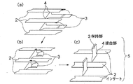
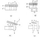
図1(c)は、本発明に係るインサート整列体5の一例である。インサート整列体5は、複数のインサート2、相隣るインサート2の間に設けられた保持部3、及びインサート2と保持部3を接合する接合部4が一体的に設けられたものである。
インサート整列体5の材質は、目的により種々の材質が使用できるが、金属であるとインサート整列体5の作成の容易さ、保持部3の耐熱性、保持部3を取り除く際の加工の容易さがある。電気・電子部品のコネクタ等では、金属が使用される。
図1(a)に示すような金属製インサート整列体5は、例えば、金属板を打ち抜き加工等により、所望の形状及び間隔でインサート2と保持部3及び接合部4が一体となって形成される。次に、図1(b)に示すように、必要であれば保持部3の端部を折り畳んだ上で、図1(c)に示すように、保持部3をインサート2に対してほぼ直角に折り曲げる。
【0008】
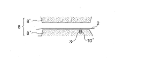
このようにして得られた金属製インサート整列体5は、例えば図2に示すように、下金型8’の上にセットされ、金型の固定部10において保持部3が所定の位置に保持される。図2では、固定部10が下金型8’に設けられた溝10’であり、溝10’の中に保持部3が挿入されて保持される。上記において「ほぼ直角に折り曲げる」とは、所定の幅の溝10’の中に保持部3が容易に挿入され、保持されるに必要な角度に折り曲げることをいう。
次に、樹脂を金型キャビティに注入するが、樹脂をインサート整列体5を挟んで、固定部10と反対側の金型キャビティ(図2ではインサート整列体5と上金型8”との間の全面)に注入して、インサート2を所定の形状にインサート成形する。この時、電気・電子部品用コネクタではインサート2の下面には樹脂が注入されず、金属表面が露出されていてもよく、露出面が導電面となる。また、用途によっては、インサート2の下面にも樹脂が充填されてもよいが、この場合にはインサートは保持部3により下金型8’から浮かせて、樹脂が回り込める空間を持たせるようにする。
一方、保持部3の固定部10に保持された側には、樹脂が実質的に注入されず、原インサート成形品1’から保持部3を取り除く際に、樹脂の注入されていない側から取り除くことができる。上記において「樹脂が実質的に注入されていない」とは、保持部3の取り除き側は樹脂で、通常は、覆われないが、取り除く操作に影響がない程度に少量の樹脂が回り込んでいても構わないことをいう。なお、保持部3の固定部10に保持された側と反対側には、樹脂が注入される。
【0009】
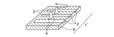
このようにして得られた原インサート成形品1’から接合部4と保持部3を取り除くことにより、複数のインサート2を有するインサート成形品1を得ることができる。図3では、成形後に接合部4を含めて保持部3をねじって取り除く例が示されている。
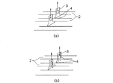
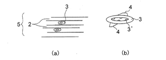
取り除くためには、保持部3に、図4(a)に示すように円形等の孔を開けたり、図4(b)に示すようにブリッジ状にして、孔等を爪で引っかけて保持部3を取り除くことができる。
上記のような、ねじり取り、折り取り、引っかけ取り、又は切り取りを行えるものを取り除き手段6とし、取り除き手段6は金型の適当なところに設けられてインサート成形品1の離型時に保持部3を取り除いたり、原インサート成形品1’を離型後に取り除き手段6を有する治具などにより取り除いたりすることができる。
【0010】
図5は、本発明に係るインサート整列体5の他の一例である。インサート整列体5の保持部3の両端部には係合部3’及び3”が設けられている。
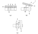
上記のインサート整列体5は、図6(a)及び図6(a’)に示すように、下金型8’の固定部10の固定爪11’及び11”の間に保持部3の係合部3’及び3”が挿入されて保持され、樹脂が注入される。なお、図6(a)は、樹脂が注入されて得られた原インサート成形品1’のインサートと直角の断面図であり、上金型8”が上に移動した(図示されない)状態を示す。図6(a’)は、図6(a)において、保持部3のインサート2と平行方向の断面図である。
したがって、保持部3は、インサート2と同一平面にすることもできる。また、保持部3を湾曲させて、固定爪11’及び11”の間に係合部3’及び3”が挿入され、保持部3が下金型8’に、必要であればバネ効果を持たせて、保持されるようにすることもできる。
インサート成形後、図6(b)に示すように、取り除き手段6(例えばエジェクタピン(6’)によりインサート成形品1を突き出して離型させるが、突き出す力で接合部4を破断して保持部3を取り除くことができる。保持部3は、固定爪11’及び11”の間に係合部3’及び3”が挿入されているので、下金型8’に残るが、図6(c)に示すように、離脱手段7(例えばエジェクタピン(7’))により突き出されて下金型8’から取り去られる。
【0011】
図7(a)は、本発明に係るインサート整列体5の更に他の一例である。図7(b)は保持部3と接合部4の拡大図を示す。インサート整列体5の保持部3はドーナツ型円板状であり、内円周上には係合部3’が複数設けられており、外円周上には接合部4が設けられている。
上記のインサート整列体5は、図8(a)に示すように、下金型8’の頭部を有する固定柱12にドーナツ型円板状の保持部3が押し込まれ、係合部3’が下金型8’と固定柱12の頭部との間に挿入され、保持部3が保持される。なお、図8(a)は、樹脂が注入されて得られた原インサート成形品1’のインサートと直角の断面図であり、上金型8”が上に移動した(図示されない)状態を示す。
したがって、保持部3は、インサート2と同一平面にすることができる。この場合、保持部3の係合部3’を下方に変形させて、係合部3’を固定柱12の頭部の下に押し込み、保持部3が下金型8’に対してバネ効果を持たせて保持させるようにすることもできる。
インサート成形後、図8(b)に示すように、取り除き手段6(例えばエジェクタピン(6’))によりインサート成形品を離型させると同時に、押し出す力で接合部を破断して保持部3を取り除くことができる。係合部3’が頭部の下に挿入された保持部3は下金型8’に残るが、図8(c)に示すように、離脱手段7(例えばエジェクタピン(7’))により下金型8’から取り除かれる。
また、保持部3のバネ効果は、インサート整列体5を金型に対して確実に保持するとともに、残った保持部3を離脱手段7により容易に取り去るように働く。
【0012】
上記において、複数のインサート2の数は、2以上であれば特に制限はないが、例えば、100等のような多数のインサートを設けることも可能である。
複数のインサート2は、所望の形状に曲げ加工などを施した後、金型内にセットすることもできる。
複数のインサート2は、それぞれ別の形状をしていてもよい。
相隣る2つのインサート2の間に設けられる保持部3は、1箇所であっても、複数箇所であってもよい。
また、別の態様としては、インサート整列体5を金型のある場所にセットし、別の種類のインサート整列体5を同じ金型の別の場所にセットして、インサート成形を行うこともできる。これにより多種類のインサートを多数設けたインサート成形品を成形することができる。
【0013】
接合部4は、必要に応じて、原インサート成形品1’から保持部3を取り除くことが容易に行えるような設計とする事が望ましい。
すなわち、接合部4が、インサート整列体5を金型8内へ挿入する際にはインサート整列体5から外れないような強度を有し、取り除く際には保持部3が取り除き易いような強度を有することが望ましい。
そのために、例えば、接合部4の厚みを、インサート2の厚みの80%以下、好ましくは80%から20%になるように部分的に厚みを薄くして接合する方法、保持部3とインサート2の接合部4の幅を2mm以下として点状もしくは細板状に接合する方法などが挙げられる。
なお、保持部3を取り除いた時、インサート2の接合部4が接合していた境界が出っ張って、コネクタとして他の端子にはめ込む際等に、不具合を生じない場所、及び形状、厚さに接合部4と保持部3を設ける。
【0014】
保持部3の形状は、保持部3が金型8に設けられた固定部10において所定の位置に保持される機構によって決められる。上記のように、保持部3の厚みは、接合部4の厚みより大きいことが望ましい。保持部の厚みが薄すぎると、成形後にインサートから保持部を取り除く際に、原インサート成形品1’からうまく取り除かれずに成形品1に残ってしまう事がある。
【0015】
このような保持部3を設け、金型8に保持部3の形状に応じた固定部を設けることにより、得られるインサート成形品は、貫通孔を設けるといった形状的な制約を受けることなく、プレス機のような特別な機械工具の必要もなく、簡便に2個以上のインサートをもつインサート成形品を製造する事が可能となる。
【0016】
インサートとして金属を使用する場合は、インサートは金属母材のみ、あるいは金属母材に鍍金をしたものでもよい。上記金属母材としては、電導性の高い金属であれば特に制限はないが、銅系、黄銅系、銀系、金系、アルミニウム系等が挙げられ、鍍金材質としてはスズ、ニッケル、金、銀等が挙げられる。
【0017】
インサート成形に使用する樹脂の種類は特に問わないが、熱硬化性であっても熱可塑性であっても構わない。熱可塑性樹脂としては、通常の射出成形が可能なものであればよく、例えば、ポリエチレン、ポリプロピレンのようなオレフィン系樹脂、ポリスチレン、ABS樹脂などのスチレン系樹脂、PMMAなどのアクリル系樹脂、ポリ塩化ビニル、熱可塑性ポリウレタン、ポリアミド、ポリアセタール、ポリカーボネイト、変性ポリフェニレンエーテル、ポリエチレンテレフタレート、ポリブチレンテレフタレートなどのポリアルキレンテレフタレート樹脂、ポリフェニレンスルフィド、ポリイミド、ポリアミドイミド、ポリエーテルイミド、ポリアリレート、ポリサルフォン、ポリエーテルサルフォン、ポリエーテルエーテルケトン、液晶性ポリマー、テトラフルオロエチレンなどの各種熱可塑性エラストマー等が挙げられる。
また、これらを主成分として、共重合可能なモノマーにより変性してあっても構わない。また、これらの1種以上を混合または併用しても構わない。その中でも、インサート成形に適したものとしては、ポリブチレンテレフタレート、液晶性ポリマー、ポリフェニレンスルフィドなどを挙げることが出来る。
熱硬化性樹脂としては、フェノール系樹脂、エポキシ系樹脂、尿素系樹脂、メラミン系樹脂、ジアリルフタレート系樹脂、不飽和ポリエステル系樹脂等が挙げられる。
【0018】
これら樹脂には、用途や目的に応じて必要な特性を付与する為に、公知の、各種添加剤を配合する事が出来る。例えば熱安定剤、酸化防止剤、核剤、可塑剤、潤滑剤、離型剤、乳化剤、顔料、光沢剤、難燃剤、静電防止剤、発泡剤、補強剤、無機または有機充填剤等を、本発明の目的を損なわない範囲で添加することができる。
耐熱性及び機械的強度等をアップする目的で、無機及び/又は有機の充填材を配合した樹脂を用いることができる。好適な充填材としては、ガラス繊維、炭素繊維、金属繊維、アラミド繊維、チタン酸カリウム、アスベスト、炭化ケイ素、セラミック、窒化ケイ素、硫酸バリウム、硫酸カルシウム、カオリン、クレー、パイロフィライト、ベントナイト、セリサイト、ゼオライト、マイカ、雲母、ネフェリンシナイト、タルク、アタルパルジャイト、ウォラストナイト、PMF、フェライト、ケイ酸カルシウム、炭酸カルシウム、炭酸マグネシウム、ドロマイト、酸化亜鉛、酸化チタン、酸化マグネシウム、酸化鉄、二硫化モリブデン、黒鉛、石こう、ガラスビーズ、ガラスパウダー、ガラスバルーン、石英、石英ガラス等の強化充填材を挙げることができる。これらは中空であってもよく、2種以上を併用することもでき、必要により、シラン系、チタン系等のカップリング剤で予備処理して使用することができる。
また、難燃性を付与するために、ハロゲン系やりん系などの難燃剤、3酸化アンチモンや5酸化アンチモンなどの難燃助剤、ドリッピング防止剤としてのフッ素系樹脂などを単独もしくは併用して使用する事が出来る。
【0019】
インサート成形法としては、射出インサート成形など従来の方法が使用できる。
【0020】
【実施例】
以下、実施例により本発明を具体的に説明するが、本発明はこれらに限定されるものではない。
実施例1(図1〜3参照)は、複数のインサートの間に接合部を介し保持部を設けて一体化したインサート整列体の接合部を、先端部を折り畳んだ後、インサートに対してほぼ直角に曲げ加工を施した例である。
インサートは、幅3mm、厚さ0.5mmの銅製端子を用いた。インサートは3個が平面状に平行に整列されている。相隣るインサート間の距離は4mmである。相隣るインサートの間には、接合部を介して保持部が設けられる。保持部は、長さ8mm、幅3mmであり、折り畳まれた後、インサートに直角に折り曲げられ、溝に挿入される長さは5mmである。接合部は、厚さ0.5mmで、接合幅1mmである。
このようなインサート整列体を60℃に温調した金型に挿入設置し、ポリブチレンテレフタレート樹脂ジュラネックスTM3316(ポリプラスチックス株式会社製)をシリンダ設定温度250℃で溶融したものを注入し、射出成形によりコネクタをインサート成形する。
保持部は、金型の溝に挿入後、折り畳んだ先端部のばね効果により、溝に挿入しても、通常の操作では溝から外れないので、インサート整列体をセットする際に、インサートの抜け落ちや浮き上がりが生じることなく、成形が行える。
インサート成形後、金型からインサート成形品を取り出し、保持部を手で折り取る事により、不要な部分を成形品に残すことなく、複数のインサートをもつインサート成形品を得ることができる。
【0021】
実施例2(図5〜6参照)では、インサート整列体は、金型に設けられた固定部に接合部を横にスライドしながら挿入する事により保持された後、樹脂でインサート成形される。インサート成形後、原インサート成形品の保持部が金型に保持された状態で、まずエジェクタピン6’(取り除き手段6)がインサート成形品を突き出す。その際に、インサートから保持部が接合部の個所で切断されてインサート成形品が取出される。
その後、エジェクタピン7’(離脱手段7)を突き出す事により固定部に残っている保持部が取り外される。
この方式では、成形後の保持部の取り除きが自動的に行われるため、後処理工程が必要無くなる。
【0022】
実施例3(図7〜8参照)は、保持部としてドーナツ状円板を使用したインサート整列体の例である。ドーナツ状円板の内側にはバネ効果を有する係合部(スナップ)が4箇所設けられている。
ドーナツ状円板の保持部は金型に設けられた頭部を有する固定柱に押し込まれて保持される。なお、固定柱の頭部の頂部は、保持部がはめやすいように、角面取りをしてテーパ状に加工されてあったほうがよい。
樹脂は、インサート整列体の上面全体に注入されるので、ドーナツ状円板の保持部の上面にも注入されるが、樹脂注型後、離型する際には、保持部が金型側に残るので、従来技術のようにプレス機で打ち抜いたりする必要がないので、貫通部を生じることがない。
この場合、エジェクタピン7’(離脱手段7)は、固定柱を取り巻く形の円筒形のスリーブとすることで、保持部を固定部から外しやすくしている。
【0023】
【発明の効果】
本発明によれば、多数のインサートを容易に金型内にインサートし、インサートが成形時の樹脂の圧力により移動せず、成形後、保持部を取り除くことが容易であり、成形サイクルの短縮が可能である。本発明のインサート成形品は貫通部を生じないので、種々の形状のインサート成形品が製造可能である。
【図面の簡単な説明】
【図1】図1(a)は、本発明に係るインサート整列体の一例の斜視図である。図1(b)は、図1(a)のインサート部を折り畳んだ状態を示す図である。図1(c)は、図1(b)の折り畳んだインサート部を直角に折り曲げた状態を示す図である。
【図2】図2は、本発明に係るインサート整列体が金型にセットされたインサート長さ方向の断面図である。
【図3】図3は、本発明に係る原インサート成形品の斜視図である。
【図4】図4(a)及び(b)は、本発明に係るインサート整列体の他の例の斜視図である。
【図5】図5は、本発明に係るインサート整列体の他の例の斜視図である。
【図6】図6(a)は、本発明に係る原インサート成形品と金型の関係を示す、インサートの幅方向の断面図である。図6(a’)は、図6(a)において、保持部3のインサートと平行方向の断面図である。図6(b)は、インサート成形品が離型される状態を示す図である。図6(c)は、離型後、保持部が取り去られる状態を示す図である。
【図7】図7(a)は、本発明に係るインサート整列体の他の例の斜視図である。図7(b)は、図7(a)の保持部の拡大斜視図である。
【図8】図8(a)は、本発明に係る原インサート成形品と金型の関係を示す、インサートの幅方向の断面図である。図8(b)は、インサート成形品が離型される状態を示す図である。図8(c)は、離型後、保持部が取り去られる状態を示す図である。
【符号の説明】
1 インサート成形品
1’原インサート成形品
2 インサート
3 保持部
3’、3”係合部
4 接合部
5 インサート整列体
6 取り除き手段
6’エジェクタピン
7 離脱手段
7’エジェクタピン
8 金型
8’下金型
8”上金型
9 樹脂
10 固定部
10’溝
11’、11”固定爪
12 固定柱[0001]
BACKGROUND OF THE INVENTION
The present invention relates to a method for manufacturing an insert molded article having a plurality of inserts. Specifically, an insert alignment body composed of a plurality of inserts and a holding portion that joins adjacent inserts via the joint portion, insert molding by injecting resin, and insert molding by removing the holding portion after molding The present invention relates to a method for manufacturing a product, and an insert-molded product obtained by the manufacturing method, in particular, an electrical / electronic component connector.
[0002]
[Prior art]
When integrating a part with a different function or material with a resin molded product, this part is bonded to a molded product prepared in advance by injection molding, etc. There is a method in which different portions are inserted into a mold, and resin is injected into the mold and bonded.
In the former case, there are many cases where problems occur in the adhesion and air tightness of the joint surface, and in order to solve this, it is necessary to pre-treat the surface of the part to be integrated in advance, the activation treatment, The burden of secondary processing costs increases.
In the latter case, when a resin molded product is molded, an extra step of inserting a part to be integrated (insert) into the mold is necessary, and the productivity is lowered due to a longer molding cycle. Furthermore, when there are a plurality of inserts, especially a large number, it is difficult to insert them into the mold at a time, and the molding cycle becomes longer. In addition, a mold having a complicated structure is required to hold a plurality of inserts in the mold, and in many cases, the inserts are moved by the pressure of the resin during molding, A problem such as contact occurred.
[0003]
Insert molding that requires multiple inserts is performed when molding connectors for electrical and electronic parts, and until now, inserts are joined together by carrier strips and integrated like hoop molding. A plurality of inserts are made independent by performing insert molding using the above-mentioned and cutting the carrier strip after molding (Japanese Patent Laid-Open No. 10-217253). However, this method has been difficult to deal with inserts with complicated shapes.
In addition, insert molding is performed in order to connect a plurality of inserts in advance, and this is inserted into a mold to simplify the structure for holding the insert. However, this method has a problem that it requires a step of integrating the insert in advance, which increases processing costs and causes an airtight defect at the interface between the integrated insert and the molded product.
In addition, insert molding is performed using inserts that are integrally molded into a shape connected by a bridge, and then the bridge is cut by punching, etc., so that the inserts are insert-molded in an independent form. There is a method of manufacturing a product. In this case, it is common to insert-mold by holding the bridge portion of the insert in the mold so as to be sandwiched between the fixed mold and the movable mold. By doing so, since there is no resin in the bridge portion and a through portion is formed, the bridge portion can be cut by punching with a press. However, in this case, since the penetrating part is formed, there is a problem that it is necessary to limit the molding to a molded article that may have the penetrating part or to refill the penetrating part with resin.
[0004]
[Problems to be solved by the invention]
It is an object of the present invention to insert a plurality of inserts in a mold in a short time, shorten the molding cycle, use a mold with a simple structure, and the insert does not move due to resin pressure during molding. Another object of the present invention is to provide a molding method capable of molding an insert molded product that is highly airtight and does not have a penetrating portion, and a molded product using the molding method.
[0005]
[Means for Solving the Problems]
The present inventors use an insert alignment body in which holding parts are joined in a dot shape between a large number of inserts, bend the holding part at a right angle, and insert the holding part into a fixing groove of the mold and hold it. Then, it was found that the above-mentioned object can be achieved by injecting the resin from the upper surface of the insert alignment body and removing the holding portion from the side where the resin is not injected after molding, thereby completing the present invention.
[0006]
That this onset bright, in the production of the insert molded article (1) having a plurality of inserts (2), in advance a plurality of inserts (2), via a joint (4), provided between the Aitonaru insert The insert alignment body (5) integrated by the holding portion (3) , which is separate from the insert, is set in the mold (8) and has a shape that provides a spring effect to the mold (8). The processed holding portion (3) is engaged and held at a predetermined position of the fixing portion (10) provided on the mold (8) so that predetermined portions of the plurality of inserts (2) are inserted. After injecting the resin (9) into the mold cavity, the holding part (3) is removed from the obtained original insert molded article (1 ') at the joint (4). that provides.
[0007]
DETAILED DESCRIPTION OF THE INVENTION
First, the present invention will be described with reference to the drawings.
FIG.1 (c) is an example of the
Various materials can be used as the material for the
The metal
[0008]
The metal
Next, the resin is injected into the mold cavity. The resin is sandwiched between the
On the other hand, the resin is not substantially injected into the side of the
[0009]
By removing the
In order to remove the hole, a circular hole or the like is formed in the holding
What can be twisted, folded, hooked or cut as described above is used as the removing
[0010]
FIG. 5 is another example of the
As shown in FIGS. 6 (a) and 6 (a ′), the above-mentioned
Therefore, the holding
After the insert molding, as shown in FIG. 6 (b), the removal means 6 (for example, the ejector pin (6 ′)) projects the insert molded
[0011]
FIG. 7A is still another example of the
As shown in FIG. 8 (a), the
Therefore, the holding
After the insert molding, as shown in FIG. 8 (b), the insert molding product is released by the removing means 6 (for example, the ejector pin (6 ′)), and at the same time, the joining portion is broken by the pushing force to hold the holding
Further, the spring effect of the holding
[0012]
In the above, the number of the plurality of
The plurality of
The plurality of
The holding
As another mode, insert molding can be performed by setting the
[0013]
It is desirable that the
That is, the
For this purpose, for example, a method in which the thickness of the joining
In addition, when the holding
[0014]
The shape of the holding
[0015]
By providing such a holding
[0016]
When metal is used as the insert, the insert may be a metal base material alone or a metal base material plated. The metal base material is not particularly limited as long as it is a highly conductive metal, but examples thereof include copper-based, brass-based, silver-based, gold-based, and aluminum-based materials, and plating materials include tin, nickel, gold, Silver etc. are mentioned.
[0017]
The type of resin used for insert molding is not particularly limited, but it may be thermosetting or thermoplastic. The thermoplastic resin may be any material that can be subjected to normal injection molding. For example, an olefin resin such as polyethylene or polypropylene, a styrene resin such as polystyrene or ABS resin, an acrylic resin such as PMMA, or a polychlorinated resin. Polyalkylene terephthalate resins such as vinyl, thermoplastic polyurethane, polyamide, polyacetal, polycarbonate, modified polyphenylene ether, polyethylene terephthalate, polybutylene terephthalate, polyphenylene sulfide, polyimide, polyamideimide, polyetherimide, polyarylate, polysulfone, polyethersulfone , Polyether ether ketone, liquid crystalline polymer, various thermoplastic elastomers such as tetrafluoroethylene, and the like.
Moreover, you may modify | denature with the monomer which can copolymerize these as a main component. One or more of these may be mixed or used together. Among them, those suitable for insert molding include polybutylene terephthalate, liquid crystalline polymer, polyphenylene sulfide and the like.
Examples of thermosetting resins include phenolic resins, epoxy resins, urea resins, melamine resins, diallyl phthalate resins, unsaturated polyester resins, and the like.
[0018]
These resins can be blended with various known additives in order to impart necessary properties depending on the application and purpose. For example, heat stabilizer, antioxidant, nucleating agent, plasticizer, lubricant, mold release agent, emulsifier, pigment, brightener, flame retardant, antistatic agent, foaming agent, reinforcing agent, inorganic or organic filler, etc. Further, it can be added within a range not impairing the object of the present invention.
For the purpose of improving heat resistance, mechanical strength, etc., a resin in which an inorganic and / or organic filler is blended can be used. Suitable fillers include glass fiber, carbon fiber, metal fiber, aramid fiber, potassium titanate, asbestos, silicon carbide, ceramic, silicon nitride, barium sulfate, calcium sulfate, kaolin, clay, pyrophyllite, bentonite, selenium. Sight, zeolite, mica, mica, nepheline cinteite, talc, atarpulgite, wollastonite, PMF, ferrite, calcium silicate, calcium carbonate, magnesium carbonate, dolomite, zinc oxide, titanium oxide, magnesium oxide, iron oxide, Examples thereof include reinforcing fillers such as molybdenum disulfide, graphite, gypsum, glass beads, glass powder, glass balloon, quartz, and quartz glass. These may be hollow and may be used in combination of two or more. If necessary, they may be pretreated with a coupling agent such as silane or titanium and used.
In addition, in order to impart flame retardancy, flame retardants such as halogen-based and phosphorus-based flame retardants such as antimony trioxide and antimony pentoxide, and fluorine resins as anti-dripping agents may be used alone or in combination. Can be used.
[0019]
As the insert molding method, a conventional method such as injection insert molding can be used.
[0020]
【Example】
EXAMPLES Hereinafter, the present invention will be specifically described with reference to examples, but the present invention is not limited thereto.
In Example 1 (see FIGS. 1 to 3), the joint portion of the insert alignment body integrated by providing a holding portion between the plurality of inserts via the joint portion is substantially the same as the insert after the tip portion is folded. This is an example of bending at a right angle.
As the insert, a copper terminal having a width of 3 mm and a thickness of 0.5 mm was used. Three inserts are aligned in parallel in a plane. The distance between adjacent inserts is 4 mm. A holding part is provided between adjacent inserts via a joint part. The holding portion has a length of 8 mm and a width of 3 mm. After being folded, the holding portion is bent at a right angle to the insert, and the length inserted into the groove is 5 mm. The joining portion has a thickness of 0.5 mm and a joining width of 1 mm.
Such an insert alignment body is inserted and installed in a mold temperature-controlled at 60 ° C., and a polybutylene terephthalate resin DURANEX ™ 3316 (manufactured by Polyplastics Co., Ltd.) melted at a cylinder set temperature of 250 ° C. is injected. The connector is insert molded by injection molding.
After the holder is inserted into the groove of the mold, due to the spring effect of the folded tip, even if it is inserted into the groove, it will not come off from the groove under normal operation. Molding can be performed without any lifting.
After the insert molding, the insert molded product is taken out from the mold, and the holding part is folded by hand, whereby an insert molded product having a plurality of inserts can be obtained without leaving an unnecessary portion in the molded product.
[0021]
In Example 2 (see FIGS. 5 to 6), the insert alignment body is held by inserting the joint portion into the fixing portion provided in the mold while sliding sideways, and then insert-molded with resin. After the insert molding, the
Thereafter, the ejector pin 7 '(detaching means 7) is ejected to remove the holding portion remaining on the fixed portion.
In this method, since the removal of the holding part after molding is automatically performed, a post-processing step is not necessary.
[0022]
Example 3 (refer FIGS. 7-8) is an example of the insert alignment body which uses a donut-shaped disk as a holding | maintenance part. Four engaging portions (snaps) having a spring effect are provided inside the donut-shaped disk.
The holding part of the donut disk is pushed and held in a fixed column having a head provided in the mold. The top of the head of the fixed column is preferably chamfered and processed into a tapered shape so that the holding portion can be easily fitted.
Since the resin is injected over the entire top surface of the insert alignment body, it is also injected into the top surface of the holding portion of the donut-shaped disk, but when the mold is released after the resin casting, the holding portion is placed on the mold side. Since it remains, there is no need to punch with a press as in the prior art, so there is no penetration.
In this case, the
[0023]
【The invention's effect】
According to the present invention, a large number of inserts can be easily inserted into the mold, the inserts do not move due to the pressure of the resin during molding, the holding part can be easily removed after molding, and the molding cycle can be shortened. Is possible. Since the insert molded product of the present invention does not generate a through portion, insert molded products having various shapes can be manufactured.
[Brief description of the drawings]
FIG. 1 (a) is a perspective view of an example of an insert alignment body according to the present invention. FIG.1 (b) is a figure which shows the state which folded the insert part of Fig.1 (a). FIG.1 (c) is a figure which shows the state which bent the insert part folded in FIG.1 (b) at right angle.
FIG. 2 is a cross-sectional view in the insert length direction in which an insert alignment body according to the present invention is set in a mold.
FIG. 3 is a perspective view of an original insert molded product according to the present invention.
4 (a) and 4 (b) are perspective views of another example of an insert alignment body according to the present invention.
FIG. 5 is a perspective view of another example of an insert alignment body according to the present invention.
FIG. 6 (a) is a cross-sectional view in the width direction of the insert showing the relationship between the original insert molded product and the mold according to the present invention. FIG. 6A is a cross-sectional view in the direction parallel to the insert of the holding
FIG. 7 (a) is a perspective view of another example of an insert alignment body according to the present invention. FIG.7 (b) is an expansion perspective view of the holding | maintenance part of Fig.7 (a).
FIG. 8 (a) is a cross-sectional view in the width direction of the insert showing the relationship between the original insert molded product and the mold according to the present invention. FIG.8 (b) is a figure which shows the state by which an insert molded product is released. FIG. 8C is a diagram illustrating a state in which the holding unit is removed after release.
[Explanation of symbols]
DESCRIPTION OF
Claims (8)
Priority Applications (1)
| Application Number | Priority Date | Filing Date | Title |
|---|---|---|---|
| JP18825199A JP4046898B2 (en) | 1999-07-01 | 1999-07-01 | Manufacturing method of insert molded product |
Applications Claiming Priority (1)
| Application Number | Priority Date | Filing Date | Title |
|---|---|---|---|
| JP18825199A JP4046898B2 (en) | 1999-07-01 | 1999-07-01 | Manufacturing method of insert molded product |
Publications (2)
| Publication Number | Publication Date |
|---|---|
| JP2001009841A JP2001009841A (en) | 2001-01-16 |
| JP4046898B2 true JP4046898B2 (en) | 2008-02-13 |
Family
ID=16220434
Family Applications (1)
| Application Number | Title | Priority Date | Filing Date |
|---|---|---|---|
| JP18825199A Expired - Fee Related JP4046898B2 (en) | 1999-07-01 | 1999-07-01 | Manufacturing method of insert molded product |
Country Status (1)
| Country | Link |
|---|---|
| JP (1) | JP4046898B2 (en) |
Families Citing this family (8)
| Publication number | Priority date | Publication date | Assignee | Title |
|---|---|---|---|---|
| AU2002951734A0 (en) | 2002-09-30 | 2002-10-17 | Cochlear Limited | Feedthrough with conductive pathways of varing configurations |
| US7950134B2 (en) | 2003-12-08 | 2011-05-31 | Cochlear Limited | Implantable antenna |
| WO2009065127A1 (en) | 2007-11-16 | 2009-05-22 | Cochlear Americas | Electrode array and method of forming an electrode array |
| JP4787629B2 (en) * | 2006-02-23 | 2011-10-05 | 株式会社オートネットワーク技術研究所 | Insert parts and manufacturing method thereof |
| US8672667B2 (en) | 2007-07-17 | 2014-03-18 | Cochlear Limited | Electrically insulative structure having holes for feedthroughs |
| JP2011104787A (en) * | 2009-11-12 | 2011-06-02 | Polyplastics Co | Method of manufacturing electric/electronic component for surface mount |
| DE102011121133A1 (en) * | 2011-12-13 | 2013-06-13 | Kostal Kontakt Systeme Gmbh | Fluid-tight contact feedthrough |
| WO2016159408A1 (en) * | 2015-03-31 | 2016-10-06 | 대우전자부품(주) | Injection molding method |
-
1999
- 1999-07-01 JP JP18825199A patent/JP4046898B2/en not_active Expired - Fee Related
Also Published As
| Publication number | Publication date |
|---|---|
| JP2001009841A (en) | 2001-01-16 |
Similar Documents
| Publication | Publication Date | Title |
|---|---|---|
| KR101561179B1 (en) | Injection moulded article and method for producing same | |
| KR101102692B1 (en) | Metal mesh contact and switch and method for producing the same | |
| JP4046898B2 (en) | Manufacturing method of insert molded product | |
| US10099423B2 (en) | Methods for joining components by heat staking | |
| JP5705930B2 (en) | Composite molded article and manufacturing method thereof | |
| JP4590258B2 (en) | Glass shelf frame forming method | |
| CN112514168B (en) | terminal | |
| KR101131594B1 (en) | Socket and header for connector and insert molding method therefor | |
| JP2019119420A (en) | Spacer for foreign object detection sensor and method for molding terminal section of foreign object detection sensor | |
| US20110094328A1 (en) | Button assembly and method of manufacturing button shaft for button assembly | |
| CN110581425A (en) | method for manufacturing integrated structural connector assembly | |
| JP6814768B2 (en) | Liquid-proof connector | |
| KR20010110957A (en) | oscillatory type actuactor | |
| JP2002321247A (en) | Manufacturing method of memory card | |
| US6416700B1 (en) | Method of producing resin-molded assembly and method producing double-retaining connector | |
| US20240006816A1 (en) | Connector with adjustable tolerance and method for manufacturing the same | |
| US20070290411A1 (en) | Method For Producing A Composite Part By Injection Moulding, Injection Compression Moulding Or Back Compression Moulding Of A Plastic Material | |
| CN110709223A (en) | Manufacturing method of bus bar and bus bar manufactured by the manufacturing method | |
| CA3099467C (en) | Moving handrail manufacturing method | |
| JP2017013441A (en) | Composite molded article and manufacturing method therefor | |
| KR200376455Y1 (en) | Sleeve pin for fixing insert at plastic injection moulding | |
| JP2004237717A (en) | Mold | |
| KR100549433B1 (en) | Electronic connector | |
| JP5071221B2 (en) | Method for producing molded product with metal plate and mold for molded product with metal plate | |
| JP5459847B2 (en) | Manufacturing method of holding jig |
Legal Events
| Date | Code | Title | Description |
|---|---|---|---|
| RD03 | Notification of appointment of power of attorney |
Free format text: JAPANESE INTERMEDIATE CODE: A7423 Effective date: 20050819 |
|
| A621 | Written request for application examination |
Effective date: 20051003 Free format text: JAPANESE INTERMEDIATE CODE: A621 |
|
| A977 | Report on retrieval |
Free format text: JAPANESE INTERMEDIATE CODE: A971007 Effective date: 20070608 |
|
| A131 | Notification of reasons for refusal |
Free format text: JAPANESE INTERMEDIATE CODE: A131 Effective date: 20070828 |
|
| A521 | Written amendment |
Free format text: JAPANESE INTERMEDIATE CODE: A523 Effective date: 20071023 |
|
| TRDD | Decision of grant or rejection written | ||
| A01 | Written decision to grant a patent or to grant a registration (utility model) |
Effective date: 20071120 Free format text: JAPANESE INTERMEDIATE CODE: A01 |
|
| A61 | First payment of annual fees (during grant procedure) |
Effective date: 20071121 Free format text: JAPANESE INTERMEDIATE CODE: A61 |
|
| FPAY | Renewal fee payment (prs date is renewal date of database) |
Free format text: PAYMENT UNTIL: 20101130 Year of fee payment: 3 |
|
| R150 | Certificate of patent (=grant) or registration of utility model |
Free format text: JAPANESE INTERMEDIATE CODE: R150 |
|
| FPAY | Renewal fee payment (prs date is renewal date of database) |
Year of fee payment: 4 Free format text: PAYMENT UNTIL: 20111130 |
|
| FPAY | Renewal fee payment (prs date is renewal date of database) |
Year of fee payment: 5 Free format text: PAYMENT UNTIL: 20121130 |
|
| FPAY | Renewal fee payment (prs date is renewal date of database) |
Year of fee payment: 5 Free format text: PAYMENT UNTIL: 20121130 |
|
| FPAY | Renewal fee payment (prs date is renewal date of database) |
Year of fee payment: 6 Free format text: PAYMENT UNTIL: 20131130 |
|
| LAPS | Cancellation because of no payment of annual fees |