JP4046858B2 - Fixing device - Google Patents
Fixing device Download PDFInfo
- Publication number
- JP4046858B2 JP4046858B2 JP18879498A JP18879498A JP4046858B2 JP 4046858 B2 JP4046858 B2 JP 4046858B2 JP 18879498 A JP18879498 A JP 18879498A JP 18879498 A JP18879498 A JP 18879498A JP 4046858 B2 JP4046858 B2 JP 4046858B2
- Authority
- JP
- Japan
- Prior art keywords
- peeling claw
- tip
- bracket
- fixing
- heating roller
- Prior art date
- Legal status (The legal status is an assumption and is not a legal conclusion. Google has not performed a legal analysis and makes no representation as to the accuracy of the status listed.)
- Expired - Fee Related
Links
Images

Landscapes
- Separation, Sorting, Adjustment, Or Bending Of Sheets To Be Conveyed (AREA)
- Fixing For Electrophotography (AREA)
- Delivering By Means Of Belts And Rollers (AREA)
Description
【0001】
【発明の属する技術分野】
本発明は、電子写真装置やプリンタ等において、定着ローラによりシート紙上のトナー像を加熱加圧定着する定着装置に関する。
【0002】
【従来の技術】
電子写真装置やプリンタ等の画像形成装置において、ヒータを内蔵する加熱ローラ及び加圧ローラからなる定着ローラのニップ部にシート紙を挿通し、トナ−像を加熱加圧定着する定着装置にあっては、定着終了後、シート紙先端にて加熱ローラ及びシート紙間に剥離爪を挿入して加熱ローラからシート紙を剥離している。そしてこの間に紙詰まりを生じると、図6に示す第1の従来例のように、剥離爪1を支持するジャム処理レバー2を矢印r方向に回動する事により剥離爪1を上方に跳ね上げて定着ローラ3から離間したり、あるいは図7に示す第2の従来例のように、ジャム処理レバー4の矢印s方向の開放により、剥離爪6をコイルスプリング等の付勢手段により矢印t方向に回動して定着ローラ7から離間した後、ジャム発生位置に手を差し込んでシート紙の除去を行っていた。
【0003】
【発明が解決しようとする課題】
しかしながら第1の従来例にあっては、上方に跳ね上げた剥離爪1の先端1aがジャム処理操作領域方向に向いているため、装置内に手を差し込んでジャム処理を行っている間に、剥離爪1の先端1aに手を触れて怪我をする可能性が有り、安全性が損なわれるという問題を有していた。一方、第2の従来例にあっては、定着ローラ7から離間した剥離爪6の先端6aが定着ローラ7に近いため、ジャム処理操作領域が狭く、シート紙Pが剥離爪6の先端6aに引っ掛かったりしてシート紙を除去し難く、操作性に劣るという問題を生じていた。
【0004】
そこで本発明は上記課題を除去するもので、ジャム処理時に、定着ローラから離間した剥離爪の先端が手に触れる事無く且つ、シート紙を除去し易くして、ジャム処理時の安全性及び操作性向上を図る定着装置を提供することを目的とする。
【0005】
【課題を解決するための手段】
本発明は上記課題を解決するため、加熱ローラ及び加圧ローラ間にトナー像を有する像支持体を挿通し前記トナー像を加熱加圧定着する一対の定着ローラと、前記トナー像の定着時にあってはブラケットに支持される剥離爪を先端が前記加熱ローラに接する剥離位置に保持し、ジャム処理時にあっては前記先端をジャム処理操作と干渉せず且つ前記加熱ローラとの間に前記ブラケットを介在してなる待避位置に保持し且つ前記先端を前記ブラケットの切欠き部に収納してなる剥離爪機構とを設けるものである。
【0006】
上記手段により本発明は、ジャム処理時、剥離爪を除去操作と干渉しない待避位置に移動し且つ剥離爪の先端を除去操作と干渉しない方向に向ける事により、ジャム処理時の安全性及び操作性向上を図るものである。
【0007】
【発明の実施の形態】
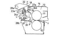
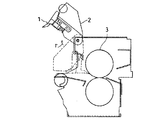
以下本発明を図1乃至図3に示す実施の形態を参照して説明する。図1は電子写真装置(図示せず)等に搭載される定着装置10の要部を示す構成図であり、ヒータ11aを内蔵する加熱ローラ11及びこの加熱ローラ11に押圧して転接する加圧ローラ12からなる一対の定着ローラ13を有している。定着ローラ13は、上ケーシング14及び下ケーシング16に囲われており、上ケーシング14には、剥離爪機構17を回動可能に支持するブラケット18が設けられている。
【0008】
剥離爪機構17は、先端20aが加熱ローラ11に摺接して、定着終了後のシート紙Pを加熱ローラ11から剥離する剥離爪20及びこの剥離爪20を移動支持するクランク機構21から成っている。クランク機構21は、第1の支点22aにてブラケット18に回動可能に軸止される回動アーム22、一端に剥離爪20を支持し他端の第2の支点23aが回動アーム22に回動可能に軸止される支持アーム23、一端の作用点24aが支持アーム23に軸止され他端の第3の支点24bがブラケット18に回動可能に軸止され、支持アーム23及びブラケット18間に掛け渡されるクランク24からなっている。
【0009】
尚26、27はシート紙Pを支持するガイド、28a,28bは定着終了後のシート紙Pを挟持搬送する上下一対の排紙ローラであり、上排紙ローラ28aは回動アーム22に支持され、ジャム処理時、回動アームの回動に伴い下排紙ローラ28bから離間されシート紙Pの搬送路30を開放するように成っている。
【0010】
次に作用について述べる。画像形成手段(図示せず)により形成されたトナー像を有するシート紙Pは、ヒータ11aにより所定温度に加熱される一対の定着ローラ13のニップを通過する間に加熱加圧定着され、この後排紙ローラ28a、28bを経て排紙トレイ(図示せず)に排出される。
【0011】
このように定着工程を行う間、剥離爪20の先端20aは加熱ローラ11に接していて、定着ローラ13のニップ通過後に加熱ローラ11に貼り付いて搬送されるシート紙Pの先端部にてシート紙Pと加熱ローラ11の間に挿通して、シート紙Pを加熱ローラ11から剥離している。
【0012】
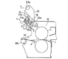
このような定着工程を行う間に紙詰まりを生じたら。電子写真装置(図示せず)の駆動を停止した後、剥離爪20を加熱ローラ11から離間してジャム処理操作を行う。即ち電子写真装置の駆動停止後、上排紙ローラ28aを保持する回動アーム22を矢印u方向に回動すると、支持アーム23にクランク24の作用点24aが軸止されていることから、回動アーム22に軸止される支持アーム23は、回動アーム22及びクランク24によりその向きを規制されながら移動され、回動アーム22に対しては第2の支点23aを軸として矢印v方向に回動しながら、先ず図2に示すように矢印w方向に移動する。これにより剥離爪20の先端20aは加熱ローラ11から離間する。
【0013】
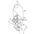
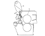
この後回動アーム22が更にu方向に回動すると、支持アーム23は、回動アーム22及びクランク24に規制され、回動アーム22に対して矢印v方向に回動しつつ矢印x方向に上昇して、図3に示すようにブラケット18に隣接する待避位置に移動される。この時剥離爪20の先端20aはクランク24の規制により、ブラケット18方向に向く。このような状態でオペレータは、定着ローラ近傍に手を差し入れジャム処理を行う。この間、剥離爪20の先端20aはオペレータの手や、シート紙Pとの干渉を生じる事が無く、安全且つスムースにジャム処理が行われる。
【0014】
ジャム処理終了後回動アーム22を矢印u方向と反対方向に回動し、上排紙ローラ28aが下排紙ローラ28bに当接する位置に戻す事により、剥離爪20は先端20aが加熱ローラ11に接する剥離位置に戻され、定着可能状態とされる。
【0015】
このように構成すれば、ジャム処理操作を行う際、ジャム処理操作領域開放のために第1のレバー22を回動すると、剥離爪20は、クランク24によりその向きを規制されながら待避位置であるブラケット18に隣接するジャム処理操作領域に干渉しない位置に移動される。これによりジャム処理操作領域を広く確保出来、ジャム処理時の操作性を向上出来る。しかも剥離爪20の先端20aはブラケット18方向を向いており、ジャム処理中に剥離爪20の先端20aが手に触れて怪我をするおそれが無く安全性も向上出来る。
【0016】
尚本発明は、上記実施の形態に限られるもので無く、その趣旨を変えない範囲での変更は可能であって、移動手段による剥離爪の移動方向等任意であり、例えば図4に示す第1の変形例のように、ジャム処理操作領域を開放するための回動アーム32の矢印y方向の回動の途中で、支持アーム32に取着される剥離爪33の先端33aをブラケット34の一部34aに摺接するよう、支持アーム32の移動をクランク36にて規制して、剥離爪33の先端33aのトナーや紙カス等の付着物37を除去するようにしても良い。このようにすれば、ジャム処理操作に伴う剥離爪33の移動時に剥離爪33の先端33aの付着物37を自動的に除去出来、別途剥離爪をクリーニングしなくても良好な剥離効果を保持できる。
【0017】
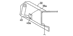
又、図5に示す第2の変形例のように、ブラケット38の一部に切欠き部38aを形成して、剥離爪40を待避位置に移動した時にその先端40aを切欠き部38aに収納するようにしても良い。このようにすれば、ジャム処理中、手やシート紙が剥離爪40の先端40aに触れるのをより確実に防止出来、一層の安全性及び操作性向上を図れる。
【0018】
【発明の効果】
以上説明したように本発明によれば、ジャム処理時に加熱ローラから離間した剥離爪をジャム処理操作領域に干渉しない待避位置に保持し、その先端をジャム処理操作領域に干渉しない方向に向ける事により、ジャム処理操作領域を広く確保し、ジャム処理操作中に剥離爪に触れて怪我をしたり、シート紙が剥離爪に引っ掛かり除去し難くなる惧れがなく、ジャム処理時の安全性及び操作性を向上出来る。
【図面の簡単な説明】
【図1】本発明の実施の形態の定着時における定着装置を示す構成図である。
【図2】本発明の実施の形態の剥離爪の移動途中における定着装置を示す構成図である。
【図3】本発明の実施の形態のジャム処理時における定着装置を示す構成図である。
【図4】本発明の第1の変形例の移動途中における剥離爪を示す説明図である。
【図5】本発明の第2の変形例のジャム処理時における剥離爪を示す構成図である。
【図6】第1の従来例のジャム処理時における定着装置を示す構成図である。
【図7】第2の従来例のジャム処理時における定着装置を示す構成図である。
【符号の説明】
10…定着装置
11…加熱ローラ
12…加圧ローラ
13…定着ローラ
14…上ケーシング
16…下ケーシング
17…剥離爪機構
18…ブラケット
20…剥離爪
21…クランク機構
22…回動アーム
23…支持アーム
24…クランク
30…搬送路[0001]
BACKGROUND OF THE INVENTION
The present invention relates to a fixing device that heats and fixes a toner image on a sheet paper by a fixing roller in an electrophotographic apparatus, a printer, or the like.
[0002]
[Prior art]
In an image forming apparatus such as an electrophotographic apparatus or a printer, a fixing apparatus that heats and fixes a toner image by inserting a sheet into a nip portion of a fixing roller including a heating roller and a pressure roller with a built-in heater. After completion of fixing, a peeling claw is inserted between the heating roller and the sheet paper at the leading edge of the sheet paper to peel the sheet paper from the heating roller. If a paper jam occurs during this time, as shown in the first conventional example shown in FIG. 6, the
[0003]
[Problems to be solved by the invention]
However, in the first conventional example, the tip 1a of the
[0004]
Accordingly, the present invention eliminates the above-mentioned problems. During the jam processing, the tip of the peeling claw separated from the fixing roller does not touch the hand, and the sheet paper can be easily removed, and the safety and operation during the jam processing. It is an object of the present invention to provide a fixing device that improves performance.
[0005]
[Means for Solving the Problems]
In order to solve the above problems, the present invention provides a pair of fixing rollers for inserting and heating an image support having a toner image between a heating roller and a pressure roller to heat and fix the toner image, and fixing the toner image. In this case, the peeling claw supported by the bracket is held at the peeling position where the tip is in contact with the heating roller, and during the jam processing, the tip does not interfere with the jam handling operation and the bracket is placed between the heating roller. A peeling claw mechanism is provided that is held in a retracted position that is interposed and that houses the tip in a notch portion of the bracket.
[0006]
By the above means, the present invention enables safety and operability during jam processing by moving the peeling claw to a retracted position that does not interfere with the removal operation and orienting the tip of the peeling claw in a direction not interfering with the removal operation. It is intended to improve.
[0007]
DETAILED DESCRIPTION OF THE INVENTION
The present invention will be described below with reference to the embodiments shown in FIGS. FIG. 1 is a configuration diagram showing a main part of a
[0008]
The
[0009]
[0010]
Next, the operation will be described. The sheet paper P having a toner image formed by image forming means (not shown) is fixed by heating and pressure while passing through the nip of the pair of
[0011]
During the fixing process as described above, the
[0012]
If a paper jam occurs during the fixing process. After the driving of the electrophotographic apparatus (not shown) is stopped, the
[0013]
Thereafter, when the
[0014]
After the jam processing is finished, the
[0015]
According to this configuration, when the jam handling operation is performed, when the
[0016]
The present invention is not limited to the above-described embodiment, and can be changed within a range that does not change the gist of the present invention, and the moving direction of the peeling claw by the moving means is arbitrary. For example, the first embodiment shown in FIG. As in the first modification, the
[0017]
Further, as in the second modification shown in FIG. 5, a
[0018]
【The invention's effect】
As described above, according to the present invention, by holding the peeling claw separated from the heating roller at the time of jam processing in a retracted position that does not interfere with the jam processing operation area, and by directing the tip thereof in a direction that does not interfere with the jam processing operation area. , Ensuring a wide area for handling jams, so that there is no risk of injury from touching the peeling nails during jam handling operations, or the sheet paper being caught by the peeling nails, making it difficult to remove. Can be improved.
[Brief description of the drawings]
FIG. 1 is a configuration diagram illustrating a fixing device during fixing according to an embodiment of the present invention.
FIG. 2 is a configuration diagram showing a fixing device in the middle of movement of a peeling claw according to an embodiment of the present invention.
FIG. 3 is a configuration diagram illustrating a fixing device during jam processing according to an embodiment of the present invention.
FIG. 4 is an explanatory view showing a peeling claw in the middle of movement according to a first modification of the present invention.
FIG. 5 is a configuration diagram showing a peeling claw during jam processing according to a second modification of the present invention.
FIG. 6 is a configuration diagram illustrating a fixing device during jam processing according to a first conventional example.
FIG. 7 is a configuration diagram illustrating a fixing device during jam processing according to a second conventional example.
[Explanation of symbols]
DESCRIPTION OF
Claims (1)
前記トナー像の定着時にあってはブラケットに支持される剥離爪を先端が前記加熱ローラに接する剥離位置に保持し、ジャム処理時にあっては前記先端をジャム処理操作と干渉せず且つ前記加熱ローラとの間に前記ブラケットを介在してなる待避位置に保持し且つ前記先端を前記ブラケットの切欠き部に収納してなる剥離爪機構とを具備する事を特徴とする定着装置。A pair of fixing rollers for inserting an image support having a toner image between a heating roller and a pressure roller to heat and fix the toner image;
At the time of fixing the toner image, the peeling claw supported by the bracket is held at the peeling position where the tip is in contact with the heating roller. At the time of jam processing, the tip does not interfere with the jam handling operation and the heating roller. And a peeling claw mechanism for holding the tip in a notch portion of the bracket and holding the bracket in a retracted position with the bracket interposed therebetween.
Priority Applications (1)
| Application Number | Priority Date | Filing Date | Title |
|---|---|---|---|
| JP18879498A JP4046858B2 (en) | 1998-07-03 | 1998-07-03 | Fixing device |
Applications Claiming Priority (1)
| Application Number | Priority Date | Filing Date | Title |
|---|---|---|---|
| JP18879498A JP4046858B2 (en) | 1998-07-03 | 1998-07-03 | Fixing device |
Publications (2)
| Publication Number | Publication Date |
|---|---|
| JP2000019885A JP2000019885A (en) | 2000-01-21 |
| JP4046858B2 true JP4046858B2 (en) | 2008-02-13 |
Family
ID=16229924
Family Applications (1)
| Application Number | Title | Priority Date | Filing Date |
|---|---|---|---|
| JP18879498A Expired - Fee Related JP4046858B2 (en) | 1998-07-03 | 1998-07-03 | Fixing device |
Country Status (1)
| Country | Link |
|---|---|
| JP (1) | JP4046858B2 (en) |
Families Citing this family (8)
| Publication number | Priority date | Publication date | Assignee | Title |
|---|---|---|---|---|
| JP2006208420A (en) | 2005-01-25 | 2006-08-10 | Kyocera Mita Corp | Image forming apparatus |
| JP4858123B2 (en) * | 2006-11-28 | 2012-01-18 | 富士ゼロックス株式会社 | Fixing apparatus and image forming apparatus |
| JP5130721B2 (en) * | 2007-01-18 | 2013-01-30 | 富士ゼロックス株式会社 | Recording medium discharge unit opening / closing device and fixing device |
| JP5142582B2 (en) * | 2007-04-20 | 2013-02-13 | キヤノン株式会社 | Image heating device |
| CN102314140A (en) * | 2010-07-02 | 2012-01-11 | 株式会社东芝 | The fixing device, image processing system and the fixation method that possess movable stripping film |
| JP5787055B2 (en) * | 2011-02-28 | 2015-09-30 | セイコーエプソン株式会社 | Recording device |
| KR101550769B1 (en) | 2011-02-28 | 2015-09-07 | 세이코 엡슨 가부시키가이샤 | Recording apparatus |
| JP6694155B2 (en) * | 2016-02-19 | 2020-05-13 | 株式会社リコー | Cooling device and image forming apparatus |
-
1998
- 1998-07-03 JP JP18879498A patent/JP4046858B2/en not_active Expired - Fee Related
Also Published As
| Publication number | Publication date |
|---|---|
| JP2000019885A (en) | 2000-01-21 |
Similar Documents
| Publication | Publication Date | Title |
|---|---|---|
| US5045887A (en) | Fixing device with a selectively movable cover | |
| JP4046858B2 (en) | Fixing device | |
| JPH02234179A (en) | Image forming device | |
| JPS6255151B2 (en) | ||
| JP3602370B2 (en) | Fixing device | |
| JPH08185076A (en) | Image forming device | |
| JPH09179427A (en) | Fixing device | |
| JP3806556B2 (en) | Image forming apparatus | |
| JP3896235B2 (en) | Image forming apparatus | |
| JPH048443Y2 (en) | ||
| JPS58196564A (en) | Fixation device | |
| JP2567284Y2 (en) | Recording paper separation promoting structure of heat roll fixing device | |
| JPS6030760Y2 (en) | Fusing device | |
| JPH02173686A (en) | Fixing device for image forming device | |
| JPS6243318Y2 (en) | ||
| JP7669831B2 (en) | Layer Transfer Device | |
| JPS6328430Y2 (en) | ||
| JPH1020593A (en) | Image forming device | |
| JPH04181977A (en) | Image forming device | |
| JPS60123877A (en) | image recording device | |
| JPH03270896A (en) | Image forming device | |
| JPH09292747A (en) | Jam removal mechanism for image forming device | |
| JP2001042750A (en) | Image forming device | |
| JPH0477316B2 (en) | ||
| JP4588900B2 (en) | Thermal fixing device and processing method in the thermal fixing device |
Legal Events
| Date | Code | Title | Description |
|---|---|---|---|
| A621 | Written request for application examination |
Free format text: JAPANESE INTERMEDIATE CODE: A621 Effective date: 20050318 |
|
| RD04 | Notification of resignation of power of attorney |
Free format text: JAPANESE INTERMEDIATE CODE: A7424 Effective date: 20050325 |
|
| A711 | Notification of change in applicant |
Free format text: JAPANESE INTERMEDIATE CODE: A711 Effective date: 20050602 |
|
| A521 | Written amendment |
Free format text: JAPANESE INTERMEDIATE CODE: A821 Effective date: 20050603 |
|
| A977 | Report on retrieval |
Free format text: JAPANESE INTERMEDIATE CODE: A971007 Effective date: 20070525 |
|
| A131 | Notification of reasons for refusal |
Free format text: JAPANESE INTERMEDIATE CODE: A131 Effective date: 20070529 |
|
| A521 | Written amendment |
Free format text: JAPANESE INTERMEDIATE CODE: A523 Effective date: 20070717 |
|
| A131 | Notification of reasons for refusal |
Free format text: JAPANESE INTERMEDIATE CODE: A131 Effective date: 20070828 |
|
| A521 | Written amendment |
Free format text: JAPANESE INTERMEDIATE CODE: A523 Effective date: 20071022 |
|
| TRDD | Decision of grant or rejection written | ||
| A01 | Written decision to grant a patent or to grant a registration (utility model) |
Free format text: JAPANESE INTERMEDIATE CODE: A01 Effective date: 20071120 |
|
| A61 | First payment of annual fees (during grant procedure) |
Free format text: JAPANESE INTERMEDIATE CODE: A61 Effective date: 20071121 |
|
| FPAY | Renewal fee payment (event date is renewal date of database) |
Free format text: PAYMENT UNTIL: 20101130 Year of fee payment: 3 |
|
| R150 | Certificate of patent or registration of utility model |
Free format text: JAPANESE INTERMEDIATE CODE: R150 |
|
| FPAY | Renewal fee payment (event date is renewal date of database) |
Free format text: PAYMENT UNTIL: 20101130 Year of fee payment: 3 |
|
| FPAY | Renewal fee payment (event date is renewal date of database) |
Free format text: PAYMENT UNTIL: 20111130 Year of fee payment: 4 |
|
| FPAY | Renewal fee payment (event date is renewal date of database) |
Free format text: PAYMENT UNTIL: 20111130 Year of fee payment: 4 |
|
| FPAY | Renewal fee payment (event date is renewal date of database) |
Free format text: PAYMENT UNTIL: 20121130 Year of fee payment: 5 |
|
| FPAY | Renewal fee payment (event date is renewal date of database) |
Free format text: PAYMENT UNTIL: 20131130 Year of fee payment: 6 |
|
| LAPS | Cancellation because of no payment of annual fees |