JP4046839B2 - Magnetic toner for developing electrostatic image and process cartridge - Google Patents
Magnetic toner for developing electrostatic image and process cartridge Download PDFInfo
- Publication number
- JP4046839B2 JP4046839B2 JP08480298A JP8480298A JP4046839B2 JP 4046839 B2 JP4046839 B2 JP 4046839B2 JP 08480298 A JP08480298 A JP 08480298A JP 8480298 A JP8480298 A JP 8480298A JP 4046839 B2 JP4046839 B2 JP 4046839B2
- Authority
- JP
- Japan
- Prior art keywords
- toner
- iron oxide
- magnetic
- magnetic iron
- content
- Prior art date
- Legal status (The legal status is an assumption and is not a legal conclusion. Google has not performed a legal analysis and makes no representation as to the accuracy of the status listed.)
- Expired - Fee Related
Links
Images
Landscapes
- Developing Agents For Electrophotography (AREA)
Description
【0001】
【発明の属する技術分野】
本発明は、電子写真法、静電記録法、磁気記録法などにおいて用いられる静電荷像現像用磁性トナー及びプロセスカートリッジに関し、形成された顕画像を記録材に加熱定着させる定着方式に供される静電荷像現像用磁性トナー及びプロセスカートリッジに関する。
【0002】
【従来の技術】
従来、電子写真法としては米国特許第2,297,691号明細書、特公昭42−23910号公報(対応米国特許第3,666,363号明細書)及び特公昭43−24748号公報(対応米国特許第4,071,361号明細書)等に記載されている如く、多数の方法が知られている。一般には光導電性物質を利用し、種々の手段により感光体上に電気的潜像を形成し、次いで該潜像をトナーを用いて現像し、トナー画像を形成して可視像とし、必要に応じて、紙の如き転写材にトナー画像を転写した後、加熱、加圧、加熱加圧の如き定着手段により定着し、複写物またはプリントを得るものである。
【0003】
静電潜像をトナーを用いて可視像化する現像方法も種々知られている。例えば米国特許第2,874,063号明細書に記載されている磁気ブラシ法、米国特許第2,618,552号明細書に記載されているカスケード現像法及び米国特許第2,221,776号明細書に記載されているパウダークラウド法、ファーブラシ現像法、液体現像法の如き多数の現像方法が知られている。これらの現像方法において、特にトナー及びキャリヤーを主体とする二成分系現像剤を用いる磁気ブラシ法、カスケード法、液体現像法などが実用化されている。これらの現像方法はいずれも比較的安定に良画像の得られる優れた方法であるが、反面キャリヤーの劣化、トナーとキャリヤーの混合比の変動という二成分系現像剤にまつわる問題点を有する。
【0004】
かかる問題点を解消するため、トナーのみよりなる一成分系現像剤を用いる現像方法が各種提案されている。中でも、磁性を有するトナー粒子よりなる一成分系現像剤を用いる方法に優れたものが多い。
【0005】
米国特許第3,909,258号明細書には、電気的に導電性を有する磁性トナーを用いて現像する現像方法が提案されている。これは、内部に磁性を有する円筒状の導電性スリーブ上に導電性磁性トナーを支持し、これを静電潜像を有する静電潜像保持体に接触せしめ現像するものである。この際、現像部において、静電潜像保持体表面とスリーブ表面の間にトナー粒子により導電路が形成され、この導電路を経てスリーブより磁性トナー粒子に電荷が導かれ、静電潜像の画像部と磁性トナーとの間のクーロン力によりトナー粒子が画像部に付着して現像される。この導電性磁性トナーを用いる現像方法は、従来の二成分現像方法にまつわる問題点を回避した優れた方法であるが、反面トナーが導電性であるため、トナー画像を有する静電潜像保持体から普通紙の如き最終的な支持部材へ静電的に転写することが困難であるという問題を有している。
【0006】
静電的に転写することが可能な高抵抗の磁性トナーを用いる現像方法として、トナー粒子の誘電分極を利用した現像方法がある。しかし、かかる方法は本質的に現像速度がおそく、現像画像の濃度が十分に得られ難いという問題点を有している。
【0007】
高抵抗の絶縁性の磁性トナーを用いるその他の現像方法として、磁性トナー粒子相互の摩擦、磁性トナー粒子とスリーブの如き摩擦部材との摩擦により磁性トナー粒子を摩擦帯電し、摩擦電荷を有する磁性トナーで静電潜像を現像する方法が知られている。しかしこれらの方法は、磁性トナー粒子と摩擦部材との接触回数が少なく摩擦帯電が不十分となり易く、また帯電した磁性トナー粒子はスリーブとの間のクーロン力が強まりスリーブ上で凝集し易いという問題点を有している。
【0008】
特開昭55−18656号公報(対応米国特許第4,395,476号及び第4,473,627号明細書)において、上述の問題点を除去したジャンピング現像方法が提案されている。これはスリーブ上に磁性トナーをきわめて薄く塗布し、これを摩擦帯電し、次いでスリーブ上の磁性トナー層を静電荷像に近接させて現像するものである。この方法は、磁性トナーをスリーブ上にきわめて薄く塗布することによりスリーブと磁性トナーの接触する機会を増し、磁性トナーの十分な摩擦帯電を可能にしたこと、及び磁力によって磁性トナーを支持し、かつ磁石と磁性トナーを相対的に移動させることにより磁性トナー粒子相互の凝集を解くと共にスリーブと十分に摩擦せしめていることによって優れた画像が得られるものである。
【0009】
上記の現像方法に用いる磁性トナー中には微粉末状の磁性体が相当量混合分散されており、該磁性体の一部がトナー粒子の表面に露出しているため、磁性体の種類が、磁性トナーの流動性及び摩擦帯電性に影響する。結果として、磁性トナーの現像特性、耐久性の如き磁性トナーに要求される種々の特性に影響を与える。
【0010】
より詳細に言えば、従来の磁性体を含有する磁性トナーを用いたジャンピング現像方法においては、長期間の繰り返しの現像工程(例えば複写)を続けると、磁性トナーを含有する一成分系現像剤の流動性が低下し、充分な摩擦帯電が得られず、帯電が不均一となりやすく、低温低湿環境下において、カブリ現象が発生しやすく、画質上の問題点となりやすい。磁性トナー粒子を構成している結着樹脂と磁性体との密着性が弱い場合には、繰り返しの現像工程により、磁性トナー粒子表面から磁性体が脱離し、トナー画像の濃度低下の如き悪影響を与える傾向がある。
【0011】
磁性トナー粒子中での磁性体の分散が不均一である場合には、磁性体を多く含有する粒径の小さな磁性トナー粒子がスリーブ上に蓄積し、画像濃度低下及びスリーブゴーストと呼ばれる濃淡のムラの発生が見られる場合もある。
【0012】
従来、磁性トナーに含有される磁性酸化鉄に関し、特開昭62−279352号公報(対応米国特許第4,820,603号明細書)、特開昭62−278131号公報(対応米国特許第4,975,214号明細書)においては、ケイ素元素を含有する磁性酸化鉄粒子を含有する磁性トナーが提案されている。
【0013】
かかる磁性酸化鉄粒子は、積極的にケイ素元素を磁性酸化鉄粒子の内部に存在させているが、該磁性酸化鉄粒子を含有する磁性トナーにおいては、磁性トナーの流動性について、さらに改良すべき点を有している。
【0014】
特公平3−9045号公報(対応欧州特許出願公開公報EP−A187434)においては、ケイ酸塩を添加することで、磁性酸化鉄粒子の形状を球形に制御する提案がされている。この方法で得られた磁性酸化鉄粒子は、粒径の制御のためにケイ酸塩を使用するため、磁性酸化鉄粒子内部にケイ素元素が多く分布し、磁性酸化鉄粒子表面におけるケイ素元素の存在量が少なく、磁性トナーの流動性の改良が不十分となりやすい。
【0015】
特開昭61−34070号公報においては、四三酸化鉄への酸化反応中にヒドロキソケイ酸塩溶液を添加して四三酸化鉄を製造する方法が提案されている。この方法による四三酸化鉄粒子は、表面近傍にSi元素を有するものの、Si元素が四三酸化鉄粒子表面近傍に層を成して存在し、表面が摩擦のごとき機械的衝撃に対して弱いという問題点を有している。
【0016】
特開平5−72801号公報(対応欧州特許出願公開公報EP−A533069)においては、磁性酸化鉄粒子中にケイ素元素を0.4〜4重量%含有し、かつ、磁性体粒子表面近傍に、全ケイ素元素含有率の44〜84%が存在する磁性酸化鉄粒子を含有した磁性トナーが提案されている。
【0017】
しかしながら、該磁性酸化鉄粒子を含有した磁性トナーにおいて、そのトナー流動性や結着樹脂と該磁性酸化鉄粒子との密着性は、改良されたものの、製造例に記載されている磁性酸化鉄粒子においては最表面にケイ酸成分が多量に存在し、磁性酸化鉄粒子表面に細孔構造が形成されており、磁性酸化鉄粒子のBET比表面積が高くなりやすく、酸磁性酸化鉄粒子を含有する磁性トナーは、高湿環境下に長期に放置した後では、摩擦帯電特性が低下する傾向にあった。
【0018】
特開平4−362954号公報(対応欧州特許出願公開公報EP−A468525)には、ケイ素元素とアルミ元素双方を含む磁性酸化鉄粒子が開示されているが、環境特性のさらなる改良が望まれている。
【0019】
特開平5−213620号公報には、ケイ素成分を含有し、かつ表面にケイ素成分が露出している磁性酸化鉄粒子が開示されているが、上述と同様環境特性のさらなる改良が望まれている。
【0020】
特開平7−239571号公報には、磁性酸化鉄粒子内にケイ素成分を含有し、さらに最表面でのFe/Si比を調節することが記載されている。これにより高湿環境下での摩擦帯電性が改良されているが、製造例に記載されている磁性酸化鉄粒子は、嵩密度が高くなりやすく、トナー化した際も、現像器内で、より締まりやすくなる。これらのトナーは、トナーの自重及び撹拌装置により圧迫を受け現像器内でトナーがパッキングを起こし易くなり、それによりスリーブへのトナーの配給不足が発生し、画像が帯状に抜けるフェーディング現象が発生し易くなる。
【0021】
特開平9−59024号公報及び9−59025号公報は、Si換算でFeに対して1.7〜4.5原子%のケイ素を含み、鉄以外の金属元素として、Mn、Zn、Ni、Cu、Al、Tiから選ばれる1種又は2種以上の金属元素をFeに対して0〜10原子%含むマグネタイト粒子に関して記載している。これにより磁気特性が改善され、帯電性を改良することはできるが、単に上記金属を添加しただけではトナーの流動性能を十分に改善するには至っておらず、更に改良すべき点を有している。
【0022】
近年、電子写真法を用いた機器は、従来の複写機以外にも、コンピューターの出力用のプリンター、ファクシミリなどにも使われ始めた。例えば、プリンター装置はLBPプリンターまたはLEDプリンターが最近の市場の主流になっており、技術の方向として、従来240、300dpiであったものが400、600、800、さらには1200、2400dpiとより高解像度になってきている。従って、現像方式もこれに伴って、より高精細が要求されてきている。コンピューターの高性能化に伴い、出力される画像はますます高精細で高画質なものが要求されており、さらに、パーソナルコンピューターの普及により、より簡単にメンテナンスを行うことができると同時に、より高い信頼性が厳しく追求されてきており、それに伴いプリンターに要求される性能はより高度になり、トナーの性能向上が達成できなければ、より優れた機械が成り立たなくなってきている。例えば、デジタルプリンター及び高細密画像のコピーにおいてトナーに要求される性能のうち最も重要なものに、定着性能がある。定着工程に関しては、種々の方法や装置が開発されているが、現在最も一般的な方法は熱ローラーによる圧着加熱方式である。この加熱ローラーによる圧着加熱方式は、トナーに対し離型性を有する材料で表面を形成した熱ローラーの表面に被定着シートのトナー像面を加圧下で接触しながら通過せしめることにより定着を行うものである。この方法は熱ローラーの表面と被定着シートのトナー像とが加圧下で接触するため、トナー像を被定着シート上に融着する際の熱効率が極めて良好であり、迅速に定着を行うことができ、高速度電子写真複写機において非常に有効である。
【0023】
従来、定着ローラー表面にトナーを付着させない目的で、例えばローラー表面をトナーに対して離型性の優れた材料、シリコーンゴムや弗素系樹脂などで形成し、さらにその表面にオフセット防止及びローラー表面の疲労を防止するためにシリコーンオイルの如き離型性の良い液体の薄膜でローラー表面を被覆することが行われている。しかしながら、この方法はトナーのオフセットを防止する点では極めて有効であるが、オフセット防止用液体を供給するために装置が必要なため、定着装置が複雑になる等の問題点を有している。
【0024】
そこでシリコーンオイルの供給装置などを用いないで、かわりにトナー中から加熱時にオフセット防止液体を供給しようという考えから、トナー中に低分子量ポリエチレン、低分子量ポリプロピレンなどの離型剤を添加する方法が提案されている。充分な効果を出すために多量にこのような添加剤を加えると、感光体へのフィルミングやキャリアやスリーブなどのトナー担持体の表面を汚染し、画像が劣化し実用上問題となる。そこで画像を劣化させない程度に少量の離型剤をトナー中に添加し、若干の離型性オイルの供給もしくはオフセットしたトナーを、巻きとり式の例えばウェブの如き部材を用いた装置でクリーニングする装置を併用することが行われている。
【0025】
しかし最近の小型化,軽量化,高信頼性の要求を考慮するとこれらの補助的な装置すら除去することが好ましい。
【0026】
トナー中に離型剤としてワックスを含有させることは知られている。例えば、特開昭52−3304号公報、特開昭52−3305号公報、特開昭57−52574号公報等の技術が開示されている。
【0027】
これらのワックス類は、トナーの低温時や高温時の耐オフセット性の向上のために用いられている。しかしながら、これらの性能を向上させる反面、耐ブロッキング性を悪化させたり、現像性が悪化したりしていた。
【0028】
また、低温領域から高温領域にかけて、よりワックス添加の効果を発揮させるために2種類以上のワックスを含有するトナーとして、例えば特公昭52−3305号公報、特開昭58−215659号公報、特開昭62−100775号公報、特開平4−124676号公報、特開平4−299357号公報、特開平4−362953号公報、特開平5−197192号公報等の技術が開示されている。
【0029】
しかし、これらのトナーにおいても、すべての性能を満足しうるものはなく、何らかの問題点を生じていた。例えば、耐高温オフセット性や現像性は優れているが低温定着性が今一歩であったり、耐低温オフセット性や低温定着性には優れているが、耐ブロッキング性にやや劣り、現像性が低下するなどの弊害があったり、低温時と高温時の耐オフセット性が両立できなかったり、遊離ワックス成分によるトナーコート不均一のためにブロッチが発生し、画像欠陥を生じたり、画像上にカブリが生じたりしていた。
【0030】
これらのトナーに含有されているワックス類は、示差走査熱量計により測定されるDSC曲線の昇温時の吸熱ピークに関して、単に幅広い又は偏った温度範囲にワックス成分が存在していたため、前記の性能を満足させるには足りないものであったり、あるいは劣化させる成分や効果の少ない成分を多く含んでいた。
【0031】
また、特開平8−278657号公報、特開平8−334919号公報、特開平8−334920号公報などには、低温定着性及び耐オフセット性に優れるトナーを得るために、2種類のワックス成分をトナーに含むことが提案されている。また、特開平7−281478号公報には、定着下限温度を下げ、ホットオフセット温度を高くするために、ポリプロピレン系樹脂と、酸変性したポリエチレン系樹脂をトナー用の離型剤として使用することが提案されている。
【0032】
しかしながら、これらの離型剤を使ったトナーでは確かに低温定着性と耐高温オフセット性の幅は拡大するものの、高度に耐久することによるトナーの劣化現象が生じ、長期間に渡って安定的に使用するには全く不充分であり、さらなるトナーの改良が望まれていた。
【0033】
また、プリンター、ファクシミリ等はパーソナルコンピューターの普及により、メンテナンス性や小型化の要求が強くなってきており、それに伴いプリンター、ファクシミリ、またパーソナル複写機等の画像形成装置本体に対し、現像装置、静電荷像を保持するための潜像保持体(感光体ドラム)、クリーナー、帯電部材等を一体化させたプロセスカートリッジを用いる方法が主流になってきている。
【0034】
さらに近年においては画像形成装置本体の更なる小型化が要求され、それに伴い、プロセスカートリッジ、現像装置の小型化も要求され、現像装置の一部であるトナー収納部を変則的な形状にする必要がでてきた。
【0035】
従来のトナー収納部は、その内部にトナーを撹拌・供給するために回転可能なトナー撹拌部材を設けている。そのため、トナー収納部の形状は略円筒形状に限定されてしまい、偏平状にしたり、角型にしたりといった設計上の自由が制限されていた。
【0036】
【発明が解決しようとする課題】
本発明の目的は、上述の如き問題点を解決した静電荷像現像用磁性トナー及びプロセスカートリッジを提供することにある。
【0037】
すなわち、本発明の目的は、いかなる環境においても高品質の画像を長期間にわたって提供し、定着性能及び耐オフセット性能を損なうことなく、また、トナー収納部が変則的な形状であっても、トナーの供給がスムーズに行える静電荷像現像用磁性トナー及びプロセスカートリッジを提供することにある。
【0038】
【課題を解決するための手段】
本発明は、結着樹脂、ワックス及び磁性酸化鉄を少なくとも含有するトナー粒子を有する静電荷像現像用磁性トナーにおいて、
該ワックスが、トナー中において透過型電子顕微鏡により観察されるワックスドメイン中に0.3乃至2.0μmのラメラ構造を有し、
該磁性酸化鉄は、鉄元素を基準として、Mn、Zn、Ni、Cuからなるグループから選択される1種以上の金属元素を0.2乃至4.0重量%含有し、さらに、ケイ素元素を0.2乃至0.8重量%含有しており、
該磁性酸化鉄は、該磁性酸化鉄の鉄元素溶解率が20重量%までに存在するMn、Zn、Ni、Cuからなるグループから選択される1種以上の金属元素の含有量B Metal と該磁性酸化鉄中に存在する該金属グループ元素の含有量A Metal との比(B Metal /A Metal )×100が40乃至100%であり、
該磁性酸化鉄は、該磁性酸化鉄の鉄元素溶解率が20重量%までに存在するケイ素元素の含有量BSiと該磁性酸化鉄中に存在する全ケイ素元素の含有量ASiとの比(BSi/ASi)×100が45乃至85%であり、且つ該磁性酸化鉄の鉄元素溶解率が10重量%までに存在するケイ素元素の含有量CSiと該含有量ASiとの比(CSi/ASi)×100が35乃至70%であることを特徴とする静電荷像現像用磁性トナーに関する。
【0039】
さらに、本発明は、画像形成装置本体に対し脱着可能に装置されるプロセスカートリッジにおいて、
該プロセスカートリッジは、静電荷像を保持するための潜像保持体;該潜像保持体に接触し、外部より電圧を印加することにより該潜像保持体を帯電するための帯電部材;及び該潜像保持体に保持されている静電荷像を現像してトナー画像を形成するためのトナーを保有している現像装置を有しており、
該現像装置は、該トナーを収納するトナー収納部と、該トナー収納部に収納されている該トナーを撹拌・供給するために往復移動可能な撹拌手段を有し、
該トナーが、上記構成の静電荷像現像用磁性トナーであるプロセスカートリッジに関する。
【0040】
【発明の実施の形態】
本発明においては、以下に説明する特徴をトナーに持たせることにより、高温高湿下においても適当な流動性能を維持し、定着・耐オフセットの幅広い範囲を確保することができ、高度な耐久によっても、長期間に渡って安定的に高品質の画像を提供できるという著しい改良効果を得ることができた。
【0041】
すなわち、ワックスが一定の大きさのラメラ構造をもつことにより、ワックスドメイン相が高剛性と高衝撃性を併せ持つことができるようになったため、高度に耐久を行った後にも、トナーに劣化を生じることがなく、好ましい高品質の画像を長期間に渡って得ることが可能となった。また、高弾性を持つために高温での耐オフセット性能も向上することが可能となった。また、特定の大きさの分散相粒径をもつために、良好に樹脂バインダーを可塑化させることが可能となり、良好な定着特性を持つことも可能となった。
【0042】
「ラメラ構造」とは、結晶性高分子の分子鎖の折り畳みによる結晶化で生じた層状構造のことであり、エネルギー的に安定な結晶構造の高次構造である。
【0043】
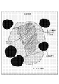
本発明の特徴としては、ワックスがトナー中において透過型電子顕微鏡により観察される分散相内で0.3〜2.0μmの層厚をもつラメラ構造を有していることであり、この具体例を図1に示した。
【0044】
すなわち、トナー中においてワックスはある程度の分散粒径を持って分布しており、そのワックス相において観察されるワックスの結晶構造が幾層にもわたる層状構造(ラメラ構造)を形成している様子が観察されている。
【0045】
トナー中におけるワックスの分散相の観察は透過型電子顕微鏡(TEM)によるトナー断面層観察により行う。
【0046】
以下に具体的方法を示す。
【0047】
すなわち、常温硬化性のエポキシ樹脂中にトナー粒子を十分分散させた後、温度40℃の雰囲気中で2日間硬化させ得られた硬化物を四酸化ルテニウム、必要によっては四酸化オスミウムを併用し染色を施した後、ダイアモンド歯を備えたミクロトームを用い薄片状のサンプルを切り出し透過型電子顕微鏡(TEM)を用いトナー粒子断面層の状態を測定する。
【0048】
本発明においては、上記のように染色されたトナー粒子断面層を透過型電子顕微鏡拡大写真(拡大倍率20万倍)で観察してワックスドメインを50個サンプリングし、サンプリングされたワックスドメインの60個数%以上(好ましくは80個数%以上)にラメラ構造が確認でき、その確認されたラメラ構造の全てについて、ラメラ構造の最大層厚部分の厚みを測定し、測定されたラメラ構造の最大層厚部分の厚みの平均値をラメラ構造の層厚と定義する。
【0049】
なお、サンプリングされたワックスドメインの60個数%以上にラメラ構造が確認できない場合には、トナー粒子断面層のワックスドメイン中にラメラ構造が形成されていないものとし、このようなトナー粒子は本発明からは除外されるものである。
【0050】
本発明においてはワックスは、トナー粒子中のワックスドメイン中に0.3〜2.0μmの層厚のラメラ構造が形成されていることを特徴とする。0.3μm未満ならば、ラメラ構造の効果が、すなわち高剛性、高衝撃性、さらに高弾性を持たなくなり、トナーの性能として発揮されない。また、2.0μmを超えるならば、ワックスの分散粒径として大きくなりすぎてしまい、チャージアップ等の帯電性能上の問題を引き起こす。さらにはワックスのフィルミングなど弊害を引き起こす原因ともなる。
【0051】
本発明においては以下の装置・方法を用いて観察を行った。
【0052】
さらに、本発明においては、磁性トナーに用いる磁性酸化鉄がケイ素元素を鉄元素を基準にして、0.2乃至0.8重量%含有しており、鉄以外の金属元素として、Mn、Zn、Ni、Cu、Co、Cr、Cd、Al、Sn及びMgからなるグループから選択される1種以上の金属元素(他金属系元素)を、鉄元素を基準として0.2乃至4.0重量%含有していることを特徴の一つとする。
【0054】
磁性酸化鉄に、これらの他種金属元素をケイ素元素と共に用いて、磁性酸化鉄表面近傍においてのケイ素化合物の析出をある程度に抑え、それを他種金属により補うことにより、磁性酸化鉄の流動性改善効果を損なうことなく、吸湿性を抑えることができる。
【0055】
本発明において、磁性酸化鉄は、ケイ素元素を鉄元素を基準として、0.2乃至0.8重量%、好ましくは0.3乃至0.7重量%含有していることが良い。
【0056】
ケイ素元素の含有率が0.2重量%未満の場合には、磁性トナーへの改善効果、特に磁性トナーの流動性の改善が弱い。ケイ素元素の含有率が0.8重量%より多い場合には、環境特性、特に高湿度環境下における長期放置及び長期耐久において、帯電特性の劣化が生じてしまい、更に磁性トナーの耐久性及びトナー結着樹脂中の磁性酸化鉄の分散性も低下する。
【0057】
他種金属元素の含有率が0.2重量%未満の場合には、トナーの流動性改良効果が少ない。他種金属元素の含有率が4.0重量%より多い場合には、磁性酸化鉄粒子が磁性トナーの帯電特性に悪影響を与え易い。
【0058】
本発明において、磁性酸化鉄中に存在する全ケイ素元素の含有量ASiと、該磁性酸化鉄の鉄元素溶解率が20重量%までに存在するケイ素元素の含有量BSiとの比(BSi/ASi)×100が45乃至85%、好ましくは50乃至80%であり、鉄元素溶解率が10%までに存在するケイ素元素の含有量CSiと全ケイ素元素の含有量ASiとの比(CSi/ASi)×100が35乃至70%、好ましくは40乃至65%であることが良い。
【0059】
(BSi/ASi)×100が45%より小さい場合、又は(CSi/ASi)×100が35%より小さい場合には、ケイ素が磁性体内部に多量に存在し、磁性酸化鉄の製造工程が悪化し易いことに加え、磁気特性が不安定な磁性酸化鉄となる場合がある。(BSi/ASi)×100が85%より大きい場合、または(CSi/ASi)×100が70%より大きい場合には、磁性酸化鉄の表層部にケイ素元素が多く存在し機械的衝撃に対してもろくなり、磁性トナーに用いた場合弊害が発生し易い。
【0060】
本発明において、磁性酸化鉄の鉄元素溶解率が20重量%までに存在するMn、Zn、Ni、Cu、Co、Cr、Cd、Al、Sn及びMgからなるグループから選択される1種以上の金属元素の含有量BMetalと該磁性酸化鉄中に存在する該金属グループ元素の含有量AMetalとの比(BMetal/AMetal)×100が40乃至100%であることが良い。(BMetal/AMetal)×100が40%未満では、他種金属が表面近傍で有効に作用し難く、製造工程においても悪化し易いことに加え、磁気特性が不安定な磁性酸化鉄となる場合がある。
【0061】
本発明において、磁性酸化鉄が他種金属元素としてMn元素を含有する場合には、磁性酸化鉄のMn元素の含有量が鉄元素を基準にして、好ましくは0.7乃至2.0重量%、より好ましくは0.8乃至1.8重量%であることが好ましい。
【0062】
Mn元素の含有量が0.7重量%より少ない場合には、磁性トナーヘの改善効果、特に磁性トナーの流動性の改善が弱い。Mn元素の含有量が2.0重量%より多い場合には、環境特性、特に高湿度環境下における長期放置及び長期耐久において、帯電特性の劣化を生じることがあり、さらに、トナーの耐久性及びトナーの結着樹脂中への磁性酸化鉄の分散性が低下し易い。
【0063】
本発明において、磁性酸化鉄中に存在する全Mn元素の含有量AMnと、該磁性酸化鉄の鉄元素溶解率が20重量%までに存在するMn元素の含有量BMnとの比BMn/AMn×100が好ましくは50乃至90%、より好ましくは60乃至85%であることが良い。BMn/AMn×100が50%より小さく、Mn元素が磁性体内部に多量に存在する場合には、製造工程が悪化し易いことに加え、磁気特性が不安定な磁性酸化鉄となる場合がある。BMn/AMn×100が90%を超える場合には、磁性酸化鉄の表層部にMn元素が多量に存在し機械的衝撃に対してもろくなり、また帯電特性に悪影響を与え易い。
【0064】
本発明において、磁性酸化鉄が、他種金属元素としてZn元素を含有する場合には、磁性酸化鉄のZn元素の含有量が鉄元素を基準にして、好ましくは0.2乃至0.8重量%、より好ましくは0.3乃至0.7重量%であることが良い。
【0065】
Zn元素の含有量が0.2重量%より少ない場合には、磁性トナーヘの流動性改善効果が弱い。Zn元素の含有量が0.8重量%より多い場合には、環境特性及び長期耐久において、帯電特性の劣化を生じることがあり、さらに、トナーの耐久性及びトナー結着樹脂中の磁性酸化鉄の分散性が低下し易い。
【0066】
本発明において、磁性酸化鉄中に存在する全Zn元素の含有量AZnと、該磁性酸化鉄の鉄元素溶解率が20重量%までに存在するZn元素の含有量BZnとの比BZn/AZn×100が、好ましくは50乃至90%、より好ましくは55乃至90%であることが良い。BZn/AZn×100が50%より小さく、Zn元素が磁性体内部に多量に存在する場合には、同様に製造工程が悪化し易いことに加え、磁気特性が不安定な磁性酸化鉄となる場合がある。BZn/AZn×100が90%を超える場合には、磁性酸化鉄の表層部にZn元素が多く存在し機械的衝撃に対してもろくなり、磁性トナーに用いた場合、弊害が発生し易い。
【0067】
本発明において、磁性酸化鉄が、他種金属元素としてCu元素を含有する場合には、磁性酸化鉄のCu元素の含有量が鉄元素を基準にして、好ましくは0.01乃至0.8重量%、より好ましくは0.05乃至0.7重量%であることが良い。
【0068】
Cu元素の含有量が0.01重量%より少ない場合には、磁性トナーヘの改善効果、特に磁性トナーの流動性の改善が弱い。Cu元素の含有率が0.8重量%より多い場合には、環境特性、特に高湿度下における長期放置及び長期耐久において、帯電特性の劣化を生じることがあり、さらに、トナーの耐久性及びトナーの結着樹脂中への磁性酸化鉄の分散性が低下し易い。
【0069】
本発明において、磁性酸化鉄中に存在する全Cu元素の含有量ACuと、該磁性酸化鉄の鉄元素溶解率が10重量%までに存在するCu元素の含有量BCuとの比BCu/ACu×100が、好ましくは70乃至100%、より好ましくは80乃至100%であることが良い。
【0070】
BCu/ACu×100が70%より小さく、Cu元素が磁性体内部に多量に存在する場合には、製造工程が悪化し易いことに加え、磁気特性が不安定な磁性酸化鉄となる場合がある。
【0071】
本発明において、磁性酸化鉄が、他種金属元素としてNi元素を含有する場合には、磁性酸化鉄のNi元素の含有量が鉄元素を基準にして、好ましくは0.1乃至0.6重量%、より好ましくは0.2乃至0.6重量%であることが良い。
【0072】
Ni元素の含有量が0.1重量%より少ない場合には、磁性トナーヘの改善効果、特に磁性トナーの流動性の改善が弱い。Ni元素の含有量が0.6重量%より多い場合には、環境特性、特に高湿度環境下における長期放置及び長期耐久において、帯電特性の劣化を生じることがあり、さらに、トナーの耐久性及びトナーの結着樹脂中への磁性酸化鉄の分散性にも劣化を生じる。
【0073】
本発明において、磁性酸化鉄中に存在する全Ni元素の含有量ANiと、該磁性酸化鉄の鉄元素溶解率が20%までに存在するNi元素の含有量BNiとの比BNi/ANi×100が、好ましくは40乃至100%、より好ましくは50乃至100%であることが良い。
【0074】
BNi/ANi×100が40%より小さく、Ni元素が磁性体内部に多量に存在する場合には、製造工程が悪化し易いことに加え、磁気特性が不安定な磁性酸化鉄となる場合がある。
【0075】
本発明において、磁性酸化鉄は、後述する測定方法に基づく球形度が、好ましくは0.8乃至1.0、より好ましくは0.82乃至1.0であることが好ましい。球形度が0.8より小さい場合には、磁性酸化鉄粒子が面と面で接触する形となり、粒径0.1乃至1.0μm付近の小さな磁性酸化鉄粒子では、機械的せん断力をもってしても容易に粒子同士を引き離すことができず、そのため、磁性トナー中への磁性酸化鉄の分散が十分に行えない場合がある。
【0076】
次に、本発明に使用される磁性酸化鉄の構成及び製造法について説明する。
【0077】
本発明に使用される磁性酸化鉄におけるケイ素元素及び他種金属元素は、基本的に該磁性酸化鉄の内部及び表面部双方に存在するものである。
【0078】
本発明の実施例に示す磁性酸化鉄を酸による溶解法により内部金属元素分布を調べたところ、磁性酸化鉄の中心部からケイ素元素及び他種金属元素は存在し、表面部に向かって含有量が傾斜的に増加していることが明らかとなった。
【0079】
本発明に係るケイ素元素を有する磁性酸化鉄は、例えば下記方法で製造される。
【0080】
第一鉄塩水溶液に所定量のMn、Zn、Ni、Cu、Co、Cr、Cd、Al、Sn及びMgから選ばれる1種以上の金属塩及びケイ酸塩を添加した後に、鉄成分に対して当量または当量以上の水酸化ナトリウムの如きアルカリを加え、水酸化第一鉄を含む水溶液を調製する。調製した水溶液のpHをpH7以上(好ましくはpH8乃至10)に維持しながら空気を吹き込み、水溶液を70℃以上に加温しながら水酸化第一鉄の酸化反応をおこない、磁性酸化鉄粒子の芯となる種晶をまず生成する。
【0081】
次に、種晶を含むスラリー状の液に前に加えたアルカリの添加量を基準として約1当量の硫酸第一鉄を含む水溶液を加える。液のpHを6乃至10に維持しながら空気を吹込みながら水酸化第一鉄の反応をすすめ種晶を芯にして磁性酸化鉄粒子を成長させる。酸化反応がすすむにつれて液のpHは酸性側に移行していくが、液のpHは6未満にしない方が好ましい。酸化反応の終期に液のpHを調整することにより、磁性酸化鉄粒子の表層および表面に他の金属化合物を所定量偏在させることが好ましい。
【0082】
添加に用いるケイ酸塩としては、ケイ酸ナトリウム及びケイ酸カリウムが例示される。添加に用いる鉄以外の金属塩としては、硫酸塩、硝酸塩、塩化物が使用できる。
【0083】
第一鉄塩としては、一般的に硫酸法チタン製造に副生する硫酸鉄、鋼板の表面洗浄に伴って副生する硫酸鉄の利用が可能であり、更に塩化鉄等可能である。
【0084】
水溶液法による磁性酸化鉄の製造方法は一般に反応時の粘度の上昇を防ぐこと、及び、硫酸鉄の溶解度から鉄濃度0.5乃至2mol/リットルが用いられる。硫酸鉄の濃度は一般に薄いほど製品の粒度が細かくなる傾向を有する。反応に際しては、空気量が多い程、そして反応温度が低いほど微粒化しやすい。
【0085】
上述の製造方法により、透過電顕写真による観察で、ケイ酸元素及び他種金属元素を有する磁性酸化鉄粒子が、主に板状面を有さない曲面で形成された球形状粒子から構成され、八面体粒子を殆ど含まない磁性酸化鉄を生成し、その磁性酸化鉄をトナーに使用することが好ましい。
【0086】
本発明において、磁性酸化鉄粒子は、後述する測定方法に基づく嵩密度が好ましくは0.4乃至0.8g/m3、より好ましくは0.5乃至0.7g/m3を満足することが好ましい傾向である。嵩密度が0.4g/m3未満の場合、トナー製造時におけるトナーの他の構成材料との物理的混合性に悪影響を及ぼし、トナー中の磁性酸化鉄の分散性が劣化する傾向にある。さらに嵩密度が0.8g/m3を超える場合、磁性トナーとした際に現像器内で締まりやすくなる傾向にあり、フェーディングが発生する場合がある。
【0087】
本発明において、磁性酸化鉄は、後述する測定方法に基づく、個数平均粒径が、0.05乃至1.00μm、より好ましくは0.10乃至0.40μmであることが、磁性トナーの結着樹脂中での分散性及び帯電の均一性の点で好ましい。磁性酸化鉄の個数平均粒径が1.00μmよりも大きい場合には、トナー中に含まれる磁性酸化鉄粒子の個数が減るために、結着樹脂中への磁性酸化鉄の分散に偏りが生じ易く、帯電の均一性が損なわれる。磁性酸化鉄の個数平均粒径が0.05μmよりも小さい場合には、磁性酸化鉄粒子間の付着力が強まり、結着樹脂中への分散性が悪化する。
【0088】
本発明における磁性酸化鉄の各種物性データの測定法を以下に詳述する。
【0089】
(1)金属元素量
本発明において、磁性酸化鉄中の鉄以外の金属元素の含有量(鉄元素を基準とする)および鉄元素の溶解率及び鉄元素溶解率に対する鉄以外の金属元素の含有量は、次のような方法によって求めることができる。例えば、5リットルのビーカーに約3リットルの脱イオン水を入れ45乃至50℃になるようにウォーターバスで加温する。約400mlの脱イオン水でスラリーとした磁性酸化鉄約25gを約300mlの脱イオン水で水洗いしながら、該脱イオン水とともに5リットルビーカー中に加える。
【0090】
次いで、温度を約50℃、撹拌スピードを約200rpmに保ちながら、特級塩酸または塩酸とフッ化水素酸との混酸を加え、溶解を開始する。このとき、塩酸水溶液は約3規定となっている。溶解開始から、すべて溶解して透明になるまでの間に数回約20mlサンプリングし、0.1μメンブランフィルターでろ過し、ろ液を採取する。ろ液をプラズマ発光分光(ICP)によって、鉄元素及び鉄元素以外の金属元素の定量を行う。
【0091】
次式によって、各サンプルごとの鉄元素溶解率が計算される。
【0092】
【数1】
【0093】
【数2】
【0094】
磁性酸化鉄の鉄元素以外の金属元素の含有量B及びCは、磁性酸化鉄の溶解率が20%或いは10%の場合に、検出される磁性酸化鉄の単位重量当たりの鉄元素以外の金属元素濃度(mg/リットル)に相当する。
【0095】
(2)磁性酸化鉄の嵩密度
本発明における磁性酸化鉄粒子の嵩密度は、JIS−K−5101の顔料試験法に準じて測定した。
【0096】
(3)磁性酸化鉄の球形度
本発明における磁性酸化鉄の球形度の算出は次のように行う。
【0097】
【数3】
【0098】
(4)磁性酸化鉄の個数平均粒径
透過電子顕微鏡写真(倍率30000倍)より写真上の粒子を無作為に100個選び、その粒子径を計測し、その平均値をもって、個数平均粒径とした。
【0099】
本発明の静電荷像現像用磁性トナーに用いられるワックスは、1〜15mgKOH/gの酸価を有することが好ましい。
【0100】
一定の酸価を持つことにより、樹脂成分への分散性を制御することが可能になるのと同時に、ワックス相の高次構造の制御を可能とすることができた。
【0101】
酸価が1mgKOH/g未満ならば、酸の効果が充分に発揮されない。また、酸価が15mgKOH/gを超える場合には、環境湿度の影響を受けやすく、安定した帯電性能を得ることが難しくなり、好ましくない。
【0102】
該ワックスのDSCによって測定される融点に由来する吸熱ピークは、110〜150℃の範囲内に存在することが低温定着の観点から好ましい。
【0103】
110℃末満ならば、保存性を損ない、耐オフセット性が悪化してしまう可能性があり好ましくなく、150℃を超えると、定着性能に悪影響を与える恐れがある。
【0104】
本発明においてワックスの融点に由来する吸熱ピーク温度の測定は示差熱分析測定装置(DSC測定装置)、DSC−7(パーキンエルマー社製)を用い、下記の条件にて測定した。
【0105】
試料 :5〜20mg、好ましくは10mg
測定法 :試料をアルミパン中に入れ、リファレンスとして空のアルミパンを用いる。
【0106】
本発明で使用されるワックスとしては、プロピレンの単独重合体、エチレンの単独重合体、プロピレンと他のオレフィン(特にエチレンが好ましい)の共重合体なとが挙げられる。
【0108】
該ワックスはエチレン−プロピレン共重合体を含むことが定着性・耐オフセット性の範囲を広範囲に保つという観点から好ましい。特にそのエチレン−プロピレン共重合体成分を3〜20重量%含むことが好ましく、更に好ましくは3〜10重量%含む。
【0109】
エチレン成分含有量が3重量%以上であることにより、ワックスの結晶性を制御し、トナー中でのワックス成分の分散性が向上し、結着樹脂に対してワックスが可塑剤として働くことによりトナーの軟化点を下げることができる。また、エチレン成分が20重量%を超えるとワックスのタック(粘性)が出ることにより、むしろ、定着特性に悪影響を与えることがあり、好ましくない揚合がある。
【0110】
また、末変性のポリプロピレン系ワックスと酸変性したポリプロピレン系ワックスを混合して用いても良い。
【0111】
ポリプロピレン系ワックスの変性に使用する酸モノマーとしては、カルボキシル基、カルボン酸無水基、カルボン酸塩基のうち少なくとも1種以上を含有するものが最も好ましい。例えば、アクリル酸、メタクリル酸、α−エチルアクリル酸、クロトン酸等のアクリル酸及びそのα−或いはβ−アルキル誘導体、フマル酸、マレイン酸、シトラコン酸等の不飽和ジカルボン酸及びそのモノエステル誘導体または無水マレイン酸等があり、このようなモノマーを単独、或いは混合して、変性反応させることにより所望の酸価を有するポリプロピレン系ワックスを得る。
【0112】
該ポリプロピレン系ワックスは、後述する樹脂重合体成分中に好ましく含まれる構成モノマーとの関係から、マレイン酸、マレイン酸ハーフエステル、マレイン酸無水物の少なくとも1種以上から選択される酸モノマーにより、変性されたポリプロピレン系ワックスであることが好ましい。
【0113】
ここで用いられるワックスの製造方法としては、エチレン、プロピレン等のオレフィンを高圧下でラジカル重合する方法、低圧下でチグラー触媒で重合する方法や、これらの方法により得られた高分子量ポリオレフィン系樹脂を熱分解する方法、一酸化炭素・水素からなる合成ガスからフィッシャー・トロプシュ法により得る方法などがあり、いずれの方法により得られたものも使用することが可能である。
【0114】
本発明に使用される結着樹脂の種類としては、例えば、ポリスチレン、ポリ−p−クロロスチレン、ポリビニルトルエン等のスチレン及びその置換体の単重合体;スチレン−p−クロルスチレン共重合体、スチレン−ビニルトルエン共重合体、スチレン−ビニルナフタリン共重合体、スチレン−アクリル酸エステル共重合体、スチレン−メタクリル酸エステル共重合体、スチレン−α−クロルメタクリル酸メチル共重合体、スチレン−アクリロニトリル共重合体、スチレン−ビニルメチルエーテル共重合体、スチレン−ビニルエチルエーテル共重合体、スチレン−ビニルメチルケトン共重合体、スチレン−ブタジエン共重合体、スチレン−イソプレン共重合体、スチレン−アクリロニトリル−インデン共重合体等のスチレン系共重合体;ポリ塩化ビニル、フェノール樹脂、天然変性フェノール樹脂、天然樹脂変性マレイン酸樹脂、アクリル樹脂、メタクリル樹脂、ポリ酢酸ビニール、シリコーン樹脂、ポリエステル樹脂、ポリウレタン樹脂、ポリアミド樹脂、フラン樹脂、エポキシ樹脂、キシレン樹脂、ポリビニルブチラール、テルペン樹脂、クマロンインデン樹脂、石油系樹脂等が使用できる。また、架橋されたスチレン系樹脂も好ましい結着樹脂である。
【0115】
スチレン系共重合体のスチレンモノマーに対するコモノマーとしては、例えば、アクリル酸、アクリル酸メチル、アクリル酸エチル、アクリル酸ブチル、アクリル酸ドデシル、アクリル酸オクチル、アクリル酸−2−エチルヘキシル、アクリル酸フェニル、メタクリル酸、メタクリル酸メチル、メタクリル酸エチル、メタクリル酸ブチル、メタクリル酸オクチル、アクリロニトリル、メタクリロニトリル、アクリルアミド等のような二重結合を有するモノカルボン酸もしくはその置換体;例えば、マレイン酸、マレイン酸ブチル、マレイン酸メチル、マレイン酸ジメチル、等のような二重結合を有するジカルボン酸及びその置換体;例えば、塩化ビニル、酢酸ビニル、安息香酸ビニル等のようなビニルエステル類、例えば、エチレン、プロピレン、ブチレン等のようなエチレン系オレフィン類;例えば、ビニルメチルケトン、ビニルヘキシルケトン等のようなビニルケトン類;例えば、ビニルメチルエーテル、ビニルエチルエーテル、ビニルイソブチルエーテル等のようなビニルエーテル類;等のビニル単量体が単独もしくは組合せて用いられる。ここで架橋剤としては、主として2個以上の重合可能な二重結合を有する化合物が用いられ、例えば、ジビニルベンゼン、ジビニルナフタレン等のような芳香族ジビニル化合物;例えば、エチレングリコールジアクリレート、エチレングリコールジメタクリレート、1,3−ブタンジオールジメタクリレート等のような二重結合を2個有するカルボン酸エステル;ジビニルアニリン、ジビニルエーテル、ジビニルスルフィド、ジビニルスルホン等のジビニル化合物;及び3個以上のビニル基を有する化合物;が単独もしくは混合物として使用できる。
【0116】
本発明において、トナーの重合体成分は実質的にテトラヒドロフラン(THF)に不溶な成分を含まないものであることが好ましい。
【0117】
THF不溶分は、トナーの重合体成分のTHF溶媒に対して不溶性となったポリマー成分(実質的に架橋ポリマー)の重量割合を示し、架橋成分を含む重合体成分の架橋の程度を示すパラメーターとして使うことができる。THF不溶分とは、以下のように測定された値を持って定義する。
【0118】
トナーサンプル0.5〜1.0gを秤量し(W1g)、円筒濾紙(例えば東洋濾紙製No.86R)に入れてソックスレー抽出器にかけ、溶媒としてTHF100〜200mlを用いて6時間抽出し、溶媒によって抽出された可溶成分をエバポレートした後、100℃で数時間真空乾燥し、THF可溶樹脂成分量を秤量する(W2g)。トナー中の磁性体、顔料及びワックスの如き樹脂成分以外の成分の重量を(W3g)とする。THF不溶分は、下記式から求められる。
【0119】
THF不溶分(%)=[{W1−(W3+W2)}/(W1−W3)]×100
THF不溶分を5重量%を超えて含有すると低温定着性が低下する。
【0120】
重合体成分のTHF可溶分により測定されるゲルパーミエーションクロマトグラフィー(GPC)のクロマトグラムが、少なくとも分子量3×10³〜3×10⁴(より好ましくは、5×10³〜2×10⁴)の領域にメインピークを有し、且つ、分子量1×10⁵〜3×10⁶(より好ましくは、5×10⁵〜1×10⁶)の領域にサブピークもしくはショルダーを有することが好ましい。
【0121】
メインピークが3×10³未満ならば、保存性・耐高温オフセット性能に悪影響を与えることがあり好ましくなく、3×10⁴を超えるならば、定着性に弊害をきたす恐れがある。また、1×10⁵〜3×10⁶の範囲にサブピークもしくはショルダーを有することにより、トナーの耐オフセット性能を向上させると共に、トナーに適度な粘度を生じるために本発明に用いられるワックスを好ましいラメラ構造を生成する高次構造に分散させることができるのである。
【0122】
本発明において、重合体成分の分子量分布は、GPC(ゲルパーミェーションクロマトグラフィ)によって次の条件で測定される。
【0123】
〈重合体のGPC測定条件〉
装置 :GPC−150C(ウォーターズ社製)
カラム:KF801〜807(ショウデックス社製)の7連
温度 :40℃
溶媒 :THF(テトラヒドロフラン)
流速 :1.0ml/min.
試料 :濃度0.05〜0.6重量%の試料を0.1ml注入
【0124】
本発明に使用される重合体成分は、0.5〜50mgKOH/gの酸価を有することが好ましい。これは本発明に用いられるワックス分散を制御し、好ましいラメラ構造を生成しやすくすると共にワックスの分散粒径も制御することができるためである。
【0125】
0.5mgKOH/g未満の酸価では、この効果を得にくくなり、50mgKOH/gを超えると、環境湿度による影響を受けやすくなり、好ましくない場合がある。
【0126】
上記の酸価を得るために用いられる重合体成分としては、カルボキシル基、カルボン酸無水基、カルボン酸塩基のうち少なくとも1種以上を含有する重合体が最も好ましい。例えば、アクリル酸、メタクリル酸、α−エチルアクリル酸、クロトン酸等のアクリル酸及びそのα−或いはβ−アルキル誘導体、フアル酸、マレイン酸、シトラコン酸等の不飽和ジカルボン酸及びそのモノエステル誘導体または無水マレイン酸等があり、このようなモノマーを単独、或いは混合して、他のモノマーと共重合させることにより所望の重合体を得る。
【0127】
この中でも特に好ましいモノマー成分として、マレイン酸、マレイン酸−ハーフエステルまたはマレイン酸無水物が挙げられる。これはマレイン酸がカルボキシル基が隣接して存在するためにより効率よく酸基の効果を導き出し、紙などの転写材との親和性を増したり、酸変性ワックスを分散させるのに好適である。
【0128】
使用される重合体成分は、低分子量重合体成分(GPCクロマトグラムにおいて分子量5×10⁴未満の領域)の酸価(AVL)と高分子量重合体(GPCクロマトグラムにおいて分子量5×10⁴以上の領域)の酸価(AVH)とが下記条件
AVL>AVH
を満足していることが好ましい。
【0129】
重合体成分の酸価がAVL>AVHであることにより、ワックスは高分子量重合体成分よりも低分子量重合体成分に、より作用し、その可塑効果により低温定着性を発揮する。
【0130】
更に、本発明で好ましく用いられる重合体成分は、低分子量重合体の酸価(AVL)が10〜35mgKOH/gであり、かつ高分子量重合体の酸価(AVH)が0.5〜11mgKOH/gであり、かつその差の関係が、3≦(AVL−AVH)≦27の範囲内であることが好ましい。
【0131】
低温定着性は、低分子量重合体成分のTg及び分子量分布に影響されるが、この成分中に酸成分を含有すること、更には高分子量重合体成分の酸価よりも3mgKOH/g以上大きくすることにより、同一のTg及び同一の分子量分布を有する酸価が上記範囲外の樹脂組成物より、低粘度化できる。
【0132】
これは、低分子量重合体成分の酸価より高分子量重合体成分の酸価を3mgKOH/g以上低く設定(酸価0.5〜11mgKOH/g)することにより、低分子量重合体成分と高分子量重合体成分及びワックスの分子鎖の絡み合いをある程度抑制し、このため、低温側での低粘度化、高温側での弾性特性維持、更には、ワックスがある程度のドメイン径を持ってトナー粒子中に存在するため、充分な離型効果が得られるものと考えられる。それにより、高速機における低温定着化、現像特性の向上につながるものである。
【0133】
一方、その酸価の差が27mgKOH/gを超えると、低分子量重合体成分と高分子量重合体成分の混合性及びトナーにした際のワックス成分の分散性に不具合が生じ、耐オフセット性及び現像性が低下する傾向にある。
【0134】
更には、低分子量重合体成分の酸価が10mgKOH/g以上の場合に、帯電の立ち上がり性が良好となる。
【0135】
一方、低分子量重合体成分の酸価が35mgKOH/gを超えると、高湿下の現像性が低下する傾向にある。
【0136】
高分子量重合体成分の酸価が0.5mgKOH/g未満の場合では、低分子量重合体成分(酸価10〜35mgKOH/g)及びワックスとの混合性が不具合となり、耐オフセット性が低下し、カブリが発生しやすくなる。
【0137】
また、前述の酸価を有するポリプロピレン系ワックスを用いた場合には、該ワックスが下記条件を満足する酸価(AVWAX)を有している。
【0138】
AVL>AVWAX,AVWAX>0(mgKOH/g)
【0139】
上記重合体成分とワックスの組み合わせにおいて、ポリプロピレン系ワックスの酸価と低分子量重合体の酸価との関係が、下記条件を満足することがトナーにとって好ましいことを見出した。
【0140】
ワックスと重合体成分中、特に低分子量重合体との相溶性を制御することにより、低温定着性、耐オフセット性を飛躍的に良化できる。
【0141】
重合体成分において、ワックス成分の酸価(AVWAX)が低分子量重合体の酸価に対し、
AVL>AVWAX
を満足する範囲で、よりトナーの流動性、帯電安定性が長時間に安定することが明らかとなった。
【0142】
ワックスの酸価が低分子量重合体の酸価に対して、AVL≦AVWAXの揚合、耐オフセット性、高湿下におけるトナー帯電性が低下する。
【0143】
より好ましくは、ワックスの酸価が低分子量重合体成分の酸価に対し、下記条件を満足することが好ましい。
【0144】
0.5×AVL>AVWAX>0.05×AVL
【0145】
本発明においてトナー重合体成分の低分子重合体成分及び高分子重合体成分の酸価(JIS酸価)は以下の方法により求める。
【0146】
〈各成分の分取〉
[装置構成]
LC−908(日本分析工業株式会社製)
JRS−86(同社;リピートインジェクタ)
JAR−2(同社;オートサンプラー)
FC−201(ギルソン社;フラクッションコレクタ)
【0147】
[カラム構成]
JAIGEL−1H〜5H直径(20mm×600mm:分取カラム)
【0148】
[測定条件]
温度:40℃
溶媒:THF
流量:5ml/min.
検出器:RI
【0149】
試料は、予め重合体成分以外の添加剤を分離しておく。分取方法としては、分子量が5×10⁴となる溶出時間を予め測定し、その前後で低分子重合体成分及び高分子重合体成分を分取する。分取したサンプルから溶剤を除去し酸価測定用試料とする。
【0150】
〈酸価の測定〉
1)試料の粉砕品0.1〜0.2gを精秤し、その重さをW(g)とする。
【0151】
2)20cc三角フラスコに試料を入れ、トルエン/エタノール(2:1)の混合溶液10ccを加え溶解する。
【0152】
3)指示薬としてフェノールフタレインのアルコール溶液数滴を加える。
【0153】
4)0.1規定のKOHのアルコール溶液を用いてフラスコ内の溶液をビュレットを用いて滴定する。この時のKOH溶液の量をS(ml)とする。同時にブランクテストをし、この時のKOH溶液の量をB(ml)とする。
【0154】
5)次式により酸価を計算する。
【0155】
【数4】
また、本発明におけるワックスの酸価は以下の測定方法により測定された。
【0157】
<ワックスの分取>
トナーサンプル0.5〜1.0gを秤量し、円筒濾紙(例えば東洋濾紙製NO.86R)に入れて、溶媒としてトルエン100〜200mlを用いて20時間ソックスレー抽出し、溶媒によって抽出された可溶成分をエバポレートした後、100℃で数時間真空乾燥する。得られた抽出物にクロロホルム20mlを加え、1時間静置した後、ポアサイズ0.45μmのメンブランフィルターで濾過し、乾燥させてワックス成分を得る。
【0158】
<酸価の測定>
・装置及び器具
直示天秤
三角フラスコ(200ml)
メスシリンダー(100ml)
ミクロビュレット(10ml)
電熱器
・試薬
キシレン
ジオキサン
N/10水酸化カリウム標準メタノール溶液
1%フェノールフタレイン溶液(指示薬)
・測定法
三角フラスコにワックス1〜1.5gを精秤し、これにキシレン20mlを加えた後、加熱溶解する。溶解後ジオキサン20mlを加え、液が濁り又はかすみを生じない間にN/10水酸化カリウム標準メタノール溶液で1%フェノールフタレイン溶液を指示薬としてできるだけ早く滴定する。同時に空試験を行う。
・計算式
酸価=[5.61×(A−B)×f]/S
但し、A:本試験に要したN/10水酸化カリウム標準メタノール溶液のml数
B:空試験に要したN/10水酸化カリウム標準メタノール溶液のml数
f:N/10水酸化カリウム標準メタノール溶液のファクター
S:試料(g)
【0159】
本発明において、磁性トナーは、必要に応じて荷電制御剤を含有しても良い。負帯電性トナーの場合には、モノアゾ染料の金属錯塩、サリチル酸、アルキルサリチル酸、ジアルキルサリチル酸またはナフトエ酸の金属錯塩の如き負荷電制御剤が用いられる。正帯電性トナーの場合には、ニグロシン系化合物、有機四級アンモニウム塩の如き正荷電制御剤が用いられる。
【0160】
荷電制御剤の含有量は、トナー結着樹脂100重量部に対し、0.5〜5重量部が好ましく、特に0.2〜3重量部が好ましい。含有量が多すぎると、トナーの流動性が悪化し、カブリが生じやすくなる。一方、少なすぎると十分な帯電量が得られにくい。
【0161】
本発明において、磁性酸化鉄は、トナー結着樹脂100重量部に対し60〜200重量部添加するのが好ましく、特に好ましくは70〜150重量部である。60重量部未満ではトナーの搬送性が不十分で現像剤担持体上の現像剤層にムラが生じ、画像ムラとなる傾向があり、さらに現像剤の帯電の過剰な上昇に起因する画像濃度の低下が生じ易い傾向であった。また、200重量部を超える場合には現像剤の帯電が充分には得られなくなるために、画像濃度低下が生じ易くなる。
【0162】
また、本発明の磁性トナーには、環境安定性、帯電安定性、現像性、流動性、保存性向上のため、無機微粉体または疎水性無機微粉体が混合されていることが好ましい。例えば、シリカ微粉末、酸化チタン微粉末又はそれらの疎水化物が挙げられる。それらは、単独あるいは併用して用いることが好ましい。
【0163】
シリカ微粉体はケイ素ハロゲン化物の蒸気相酸化により生成されたいわゆる乾式法又はヒュームドシリカと称される乾式シリカ、及び水ガラス等から製造されるいわゆる湿式シリカの両者が使用可能であるが、表面及び内部にあるシラノール基が少なく、またNa2O、SO3 2-等の製造残渣の少ない乾式シリカの方が好ましい。また乾式シリカにおいては、製造工程において例えば、塩化アルミニウム、塩化チタン等、他の金属ハロゲン化合物をケイ素ハロゲン化合物と共に用いることによって、シリカと他の金属酸化物の複合微粉体を得ることも可能であり、それらも包含する。
【0164】
さらにシリカ微粉体は疎水化処理されているものが好ましい。疎水化処理するには、シリカ微粉体と反応あるいは物理吸着する有機ケイ素化含物等で化学的に処理することによって付与される。好ましい方法としては、ケイ素ハロゲン化合物の蒸気相酸化により生成された乾式シリカ微粉体をシランカップリング剤で処理した後、あるいはシランカップリング剤で処理すると同時にシリコーンオイルのごとき有機ケイ素化合物で処理する方法が挙げられる。
【0165】
疎水化処理に使用されるシランカップリング剤としては、例えばヘキサメチルジシラザン、トリメチルシラン、トリメチルクロルシラン、トリメチルエトキシシラン、ジメチルジクロルシラン、メチルトリクロルシラン、アリルジメチルクロルシラン、アリルフェニルジクロルシラン、ベンジルジメチルクロルシラン、ブロムメチルジメチルクロルシラン、α−クロルエチルトリクロルシラン、β−クロルエチルトリクロルシラン、クロルメチルジメチルクロルシラン、トリオルガノシリルメルカプタン、トリメチルシリルメルカプタン、トリオルガノシリルアクリレート、ビニルジメチルアセトキシシラン、ジメチルジエトキシシラン、ジメチルジメトキシシラン、ジフェニルジエトキシシラン、ヘキサメチルジシロキサン、1,3−ジビニルテトラメチルジシロキサン、1,3−ジフェニルテトラメチルジシロキサン及び1分子当たり2から12個のシロキサン単位を有し末端に位置する単位にそれぞれ1個宛のケイ素原子に結合した水酸基を含有したジメチルポリシロキサン等が挙げられる。
【0166】
好ましいシリコーンオイルとしては、25℃における粘度が30〜1000センチストークスの物が用いられ、例えばジメチルシリコーンオイル、メチルフェニルシリコーンオイル、α−メチルスチレン変性シリコーンオイル、クロムフェニルシリコーンオイル、フッ素変性シリコーンオイル等が特に好ましい。
【0167】
シリコーンオイル処理の方法としては、例えばシランカップリング剤で処理されたシリカ微粉体とシリコーンオイルとをヘンシェルミキサー等の混合機を用いて直接混合してもよいし、ベースとなる微粉体にシリコーンオイルを噴霧する方法を用いてもよい。あるいは適当な溶剤にシリコーンオイルを溶解あるいは分散せしめた後、シリカ微粉体を加え混合し溶剤を除去する方法でもよい。
【0168】
本発明の静電荷像現像用磁性トナーには、必要に応じてシリカ微粉体又は酸化チタン微粉体以外の外部添加剤を添加してもよい。例えば帯電補助剤、導電性付与剤、流動性付与剤、ケーキング防止剤、熱ロール定着時の離型剤、滑剤、研磨剤等の働きをする樹脂微粒子や無機微粒子などである。例えばテフロン、ステアリン酸亜鉛、ポリフッ化ビニリデンの如き滑剤、中でもポリフッ化ビニリデンが好ましい。あるいは酸化セリウム、炭化ケイ素、チタン酸ストロンチウム等の研磨剤、中でもチタン酸ストロンチウムが好ましい。あるいは例えば酸化チタン、酸化アルミニウム等の流動性付与剤、中でも特に疎水性のものが好ましい。ケーキング防止剤、あるいはカーボンブラック、酸化亜鉛、酸化アンチモン、酸化スズ等の導電性付与剤、また、逆極性の白色微粒子及び黒色微粒子を現像性向上剤として少量用いることもできる。トナーと混合される樹脂微粒子または無機微粉体または疎水性無機微粉体などは、磁性トナー100重量部に対して0.1〜5重量部(好ましくは、0.1〜3重量部)使用するのがよい。
【0169】
本発明の静電荷像現像用磁性トナーは、トナー構成材料をボールミルの如き混合機により充分混合してから加熱ロール、ニーダー、エクストルーダーの如き熱混練機を用いて溶融、捏和及び練肉し、冷却固化後粉砕及び厳密な分級を行うことにより生成することができる。
【0170】
その中でも、溶融混練工程では、トナー構成材料の分散が良好で、連続生産が可能であること等の理由から一軸或いは二軸方式の押出混練機が用いられる。特にワックスの存在状態を制御する上で二軸押出混練機が好ましい。
【0171】
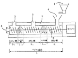
一般に二軸押出混練機には、温度を一定に保つ加熱シリンダーの中に2本のパドルと呼ばれる回転軸が通っている。原材料は加熱シリンダーの一端から供給され、加熱されて溶融状態になりつつパドルの回転により混練されてもう一端より押出される。途中に脱気を主な目的とするベント孔を設置することもある。
【0172】
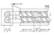
図2に本発明に好ましく用いられる押出混練機の概略図を示し、図3にパドルの模式的説明図を示す。
【0173】
パドル2の断面は、図のようなプロペラ状のものや、三角形のもの等が使用され、常に一方の先端が他方を擦るがごとく回転するように、位相をずらせてセットされている。この構造により、混練物をパドルおよびシリンダー壁に付着することなしに、前方へ送るセルフクリーニング作用を持つ。2本のパドル2の回転方向は同方向、異方向とも用いられるが、同方向が一般的である。
【0174】
パドル2は大別して2種類の部分から成り立っており、一つは混練物を加熱しつつ前方へ送る機能を有する送りスクリュー部で、もう一つは混練物を前方へ送る効果がほとんどなく、混練物が滞留・充満し、そしてパドルの回転に伴って圧縮・延伸の体積変化により混練を行うニーディング部である。
【0175】
本発明のように低温定着を目的とした軟質なトナー組成物を混練する場合、スクリュー部での混練は殆ど無いので、ニーディング部が短い場合には混練物の滞留が殆ど無くなり、トナー組成物を構成する原材料が完全に溶融状態に達する前に押出されることになる。溶融状態でのワックスの分散状態やワックスの高次構造に対して大きな影響を与える条件となる。従って、押出混練機の如き溶融混練装置を用いる場合、パドル構成、特にニーディング部の長さや配置の仕方が重要となる。
【0176】
図2のようにニーディング部を2ケ所以上設けることで、各トナー構成材料の再凝集を防止し、良好な分散性が得られる。特にパドルの全長(L)に対する全ニーディング部の長さの総計[Ln;Ln=Ln1+Ln2+……]の割合(Ln/L)を15〜35%とすると、分散性を損うことなく溶融混練時に混練物に掛かる剪断力が適正化され、各トナー構成成分、特にワックスの再凝集と結着樹脂の分子鎖の切断が抑制される。特にパドルの後半部分に存在するニーディング部の長さLeがパドル全長Lに対する割合(Le/L)が5〜10%である時にこの効果が顕著である。これらのパドル構成は、さらにワックスの分散相中での結晶構造や高次構造にも影響を与え、本発明で見出されたワックスのラメラ構造を構成しやすくなる。これらの効果によって、現像性と耐高温オフセット性を良好にすることができるのである。
【0177】
ニーディング部が1ケ所である場合、混練物の滞留が短かったり、スクリュー部での再凝集が促進され、分散性不良を生じ易い。また、分散性を改善するためにニーディング部を長くすると、混練時にかかる剪断力が大きくなってしまうために樹脂温度が上昇してしまいワックスの再凝集化を促進し、好ましい結晶系を得られず、現像性に対して好ましくない影響を与えたり、分子鎖の切断が促進され、耐高温オフセット性が低下するなどの弊害を引き起こすことがある。特にパドルの後半部分に存在するニーディング部は、出口から吐出される混練物の構成に大きく影響を与えるために、より重要である。
【0178】
好ましいワックスドメインのラメラ構造を得るためには、さらに上記装置より吐出される混練物を、吐出口へ向けて送風される送風式冷却装置により急冷され、かつ、上記混練物を15℃以下、好ましくは10℃以下に設定された冷却装置(冷却を用いて温度を一定に保った冷却コンベアなど)にて急冷することが好ましい。この急冷により、上記混練装置で得られたワックスドメインの分散状態・結晶高次構造を保つことができ、再凝集等によるワックス分散状態の変化を防ぐことに効果があり、好ましい。
【0179】
本発明においては、以下に説明する特徴をプロセスカートリッジにもたせることにより、トナー収納部を略円筒形状にする必要がなく、変則的な形状のトナー収納部にしても、トナーが収納部内でパッキングが発生せず、スリーブへのトナー供給がスムーズにおこなえ、画像が帯状に抜けるフェーディング現象が発生しないプロセスカートリッジを得ることができた。
【0180】
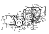
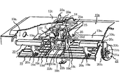
プロセスカートリッジは、静電荷像を保持するための潜像保持体と、少なくとも1つのプロセス手段を備えたものである。ここでプロセス手段としては、例えば潜像保持体の表面を帯電させる帯電部、潜像保持体にトナー像を形成する現像手段、潜像保持体表面に残留したトナーをクリーニングするためのクリーニング手段等がある。本発明のプロセスカートリッジは、図4に示すように、潜像保持体である電子写真感光体ドラム7の周囲に帯電手段8、露光部9、現像手段10、クリーニング手段11を配置し、これらをハウジング12で覆って一体化し、更にシャッタ部材28を取り付けて構成し、これを装置本体に着脱可能に構成している。
【0181】
本発明のプロセスカートリッジを構成する感光体ドラム7は、円筒状のアルミニウムからなるドラム基体の外周面に有機感光層を塗布して構成している。この感光体ドラム7を枠体に回動可能に取り付け、後述するように感光体ドラム7の長手方向一方端に固着したフランジギヤに装置本体側に設けた駆動モータの駆動力を伝達することにより、感光体ドラム7を画像形成動作に回転させる。
【0182】
本発明のプロセスカートリッジを構成する帯電部材は、前記感光体ドラム7の表面を一様に帯電させるためのものであり、本実施例では枠体に帯電ローラ8を回動自在に取り付けた、所謂接触帯電方法を用いている。帯電ローラ8は金属製のローラ軸8aに導電性の弾性層を設け、更にその上に高抵抗の弾性層を設け、更にその表面に保護膜を設けてなる。導電性の弾性層は、EPDMやNBR等の弾性ゴム層にカーボンを分散したもので構成し、ローラ軸8aに供給されるバイアス電圧を導く作用をなす。また高抵抗の弾性層はウレタンゴム等で構成し、微量の導電性微粉末を含有するものが一例としてあげられ、感光体ドラム7のピンホールや導電度の高い帯電ローラが相対した場合でも、感光体ドラム7へのリーク電流を制限してバイアス電圧の急降下を防ぐ作用をなす。また保護層はN−メチルメトキシ化ナイロンで構成し、導電性弾性層や高抵抗の弾性層の組成物質が、感光体ドラム7に触れて感光体ドラム7の表面を変質させることがないように作用する。そして前記帯電ローラ8を感光体ドラム7に接触させ、画像形成に際しては帯電ローラ8が感光体ドラム7の回転に従動して回転し、このとき帯電ローラ8に直流電圧と交流電圧とを重畳して印加することにより感光体ドラム7の表面を均一に帯電させる。
【0183】
本発明のプロセスカートリッジを構成する露光部9は、前記帯電ローラ8によって均一に帯電した感光体ドラム7の表面に、光学系から照射される光像を露光して該ドラム7表面に静電潜像を形成するためのものであり、カートリッジ枠体の上面に前記光像を導くための開口9を設けることによって露光部を構成している。
【0184】
本発明のプロセスカートリッジを構成する現像装置10は、図4に示すように、トナー収納部であるトナー収納容器10a内にトナーを収納してあり、且つ後述するように前記トナーを送り出すと共に撹拌する撹拌部材が往復移動可能に設けてある。そしてトナー収納容器10aの開口部には内部に非回転の磁石10bを有し、回転することによって表面に薄いトナー層を形成する現像スリーブ10cが感光体ドラム7と微少間隙を隔てて設けてある。現像スリーブ10cはアルミニウム製円筒状部材の表面をサンドブラスト処理等により粗面化し、その上に顔料分散した導電性塗料を塗布して構成しており、この現像スリーブ10cの表面にトナー層が形成されるとき、トナーと現像スリーブ10cとの摩擦によって感光体ドラム7上の静電潜像を現像するのに充分な摩擦帯電電荷を得る。またトナーの層厚を規制するために現像ブレード10dが設けてある。尚、前記トナー収納容器10a内にはトナーを撹拌、供給するための撹拌部材が設けられているが、トナー撹拌構成については後述する。
【0185】
本発明のプロセスカートリッジを構成するクリーニング手段11の構成は、図4に示すように、感光体ドラム7の表面に接触し、該ドラム7に残留したトナーを掻き落とすためのクリーニングブレード11aと、前記掻き落としたトナーを掬い取るために前記ブレード11aの下方に位置し、且つ感光体ドラム7の表面に弱く接触したスクイシート11bと、前記掬い取った廃トナーを溜めるための廃トナー溜め11cとで構成している。
【0186】
本発明のプロセスカートリッジを構成する撹拌手段は、トナー収納容器10a内のトナーを撹拌して現像スリーブ10cへ送り出すものであり、図5に示すように、トナー収納容器10a内に撹拌部材19と撹拌アーム20とを設けて構成している。撹拌部材19は、断面が三角形状の棒状部材を複数本一定間隔を隔てて連結して一体化したものであり、この撹拌部材19の先端辺側に設けた軸19aを、撹拌アーム20の孔20aに嵌合している。撹拌アーム20は、トナー収納容器10aの側面壁10a1,10a2に、回動軸20cを中心に回動可能に軸支され、その一端はトナー収納容器10aの側面壁10a2より外側に延び、その先端には駆動アーム20bが一体的に形成してある。トナー収納容器10aの側面壁10a2の外側には撹拌ギア21が設けてあり、感光体ドラム7の回転と共に回転軸21aを中心に回転する。この撹拌ギア21の側面には回転軸21aより偏心した偏心ダボ21bが設けてあり、駆動アーム20bの長孔20b1に嵌合している。感光体ドラム7の回転に伴って同一駆動源から駆動伝達を受けて撹拌ギア21が回転すると、撹拌アーム20は回動軸20cを中心に、図5の矢印X方向へ往復回動し、撹拌部材19はトナー収納容器10aの底面壁10a3に沿って、図5の矢印Y方向へ往復移動してトナーの凝集や偏在を防止する。また前記トナー収納容器10aの底面壁10a3は、トナーが現像スリーブ10cへ送られ易いように、現像スリーブ10c側が下がった斜面に形成してあり、撹拌部材19がトナー収納容器10aの底面に沿って矢印Y方向へ往復移動することにより、トナーが現像スリーブ10c方向へ送り込まれる。
【0187】
【実施例】
以下、本発明を製造例、実施例により具体的に説明する。尚、実施例において、「部」及び「%」は、特に記載のない場合には、「重量部」及び「重量%」を意味する。
【0188】
磁性酸化鉄の製造:
[製造例1]
硫酸第一鉄水溶液中に、鉄元素に対しケイ素元素の含有率が1.6%となるようにケイ酸ソーダを添加し、更に鉄元素に対し亜鉛元素の含有率が0.6%となるように硫酸亜鉛を添加した後、鉄イオンに対して1.0〜1.1当量の苛性ソーダ溶液を混合し、水酸化第一鉄を含む水溶液を調製した。
【0189】
水溶液のpHをpH7乃至10(例えばpH9)に維持しながら、空気を吹き込み、80乃至90℃で酸化反応を行い、種晶を生成させるスラリー液を調製した。
【0190】
次いで、このスラリー液に当初のアルカリ量(ケイ酸ソーダのナトリウム成分及び苛性ソーダのナトリウム成分)に対し0.9乃至1.2当量となるよう硫酸第一鉄水溶液を加えた後、スラリー液のpH6乃至10(例えばpH8)に維持して、空気を吹込みながら酸化反応をすすめ、酸化反応の終期にpHを調整し、磁性酸化鉄粒子表面にケイ酸成分及び亜鉛成分を偏在させた。生成した磁性酸化鉄粒子を常法により洗浄、濾過、乾燥し、次いで凝集しているのを解砕処理し、磁性酸化鉄Aを得た。
【0191】
得られた磁性酸化鉄の鉄元素とケイ素元素及び他種金属元素の溶解量の関係及び特性を表1に示す。
【0192】
[製造例2〜6]
ケイ酸ソーダの添加量、他種金属塩の添加量を表1に示す通りになるように変えた以外は、製造例1と同様にして表1に示す特性の磁性酸化鉄B〜Fを得た。
【0193】
[比較製造例1]
製造例1でケイ酸ソーダと硫酸亜鉛を添加しない以外は製造例1と同様にして表1に示すような特性を有する磁性酸化鉄aを得た。
【0194】
[比較製造例2]
比較製造例1により得られた磁性酸化鉄100部に対して、0.7部のケイ酸微粉体をヘンシェルミキサーで混合し表1に示すような特性を有する磁性酸化鉄bを得た。
【0195】
[比較製造例3〜7]
ケイ酸ソーダの添加量、他種金属塩の添加量を表1に示す通りになるように変えた以外は、製造例1と同様にして表1に示す特性の磁性酸化鉄c〜gを得た。
【0196】
【表1】
[実施例1]
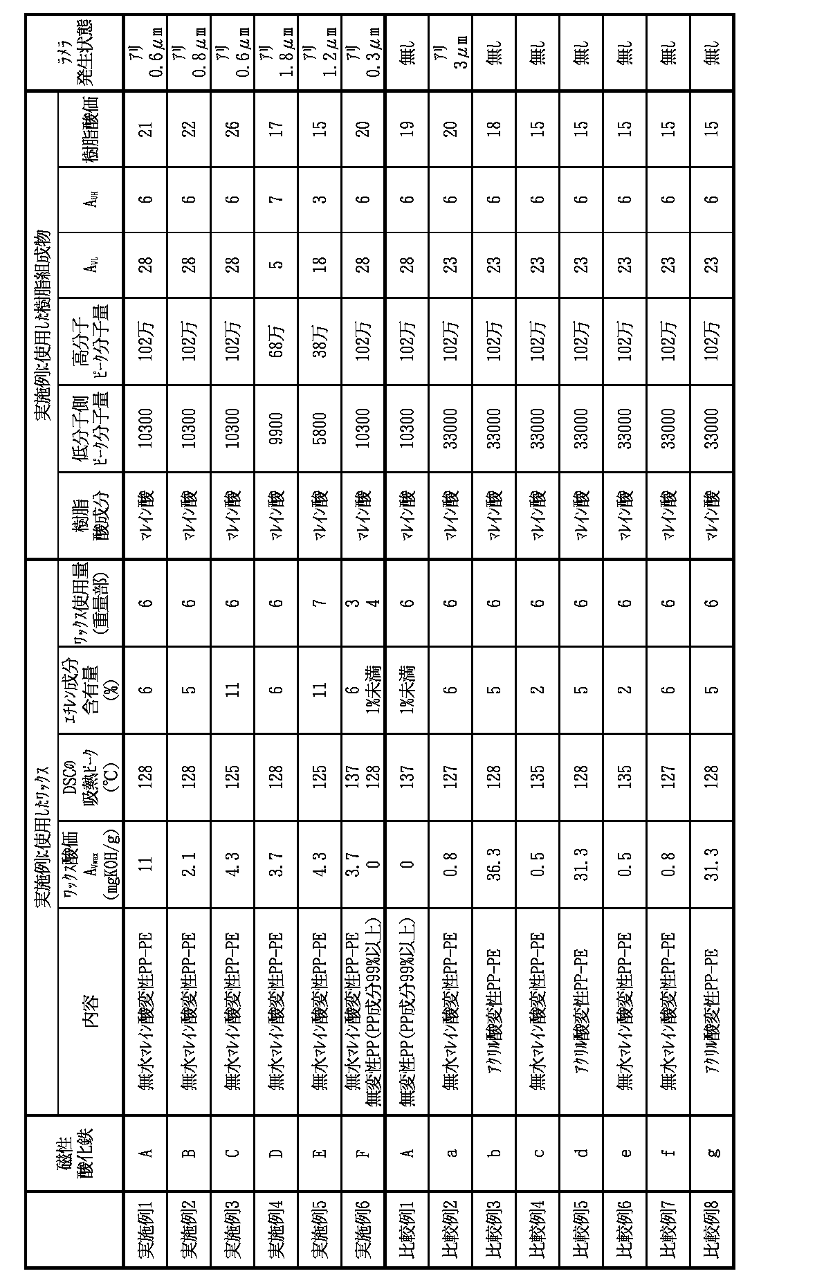
低分子量重合体として、既知の方法により合成されたスチレン−アクリル酸ブチル−マレイン酸モノブチル共重合体(L1)(ピーク分子量10300、酸価28mgKOH/g)を、高分子量重合体として、既知の方法によりスチレン−アクリル酸ブチル−マレイン酸モノブチル共重合体(H1)(ピーク分子量102万、酸価6mgKOH/g)をそれぞれ得た。低分子量重合体(L1)70部と、高分子量重合体(H1)を30部を、還流キシレン100部に溶解させた後、有機溶剤を留去し、得られた樹脂を冷却固化した後、粉砕しトナー用樹脂原材料とした。樹脂の物性を表2に示す。
・上記トナー用樹脂共重合体(酸価21mgKOH/g) 100部
・製造例1の磁性酸化鉄粒子A 95部
・負荷電制御剤(金属錯体型モノアゾ化合物) 2部
・無水マレイン酸変性プロピレン−エチレン共重合体(表2参照) 6部
(エチレン成分6%、酸価11mgKOH/g、DSCピーク128℃)
【0198】
上記混合物を、140℃に加熱された二軸エクストルーダーで溶融混練した。二軸エクストルーダーとしては、パドル全長Lを3000mmとし、パドルの2ケ所に分けてニーディング部が存在し、原材料混合物フィード(入口)側に近い方(前半分に存在する)のニーディング部の長さLn1が600mm、出口側に近い方(後半分に存在する)のニーディング部の長さLn2=Leが200mmであるパドルの構成とした。基準状態(0℃、101.3kPa)において15m3/minの風量で送風する送風式冷却装置を混練装置の吐出部に設置し、冷風温度を10℃に設定した冷風を混練装置の吐出部から吐出される混練物に吹き付けて混練物を急冷し、さらに、冷却水をコンベア内に通すことによって温度を15℃に保った冷却コンベアで混練物を搬送しながら急冷した。この冷却された混練物をハンマーミルで粗粉砕し、更にジェットミルで微粉砕した後、得られた微粉砕粉を固定壁型風力分級機で分級して分級粉を生成した。さらに、得られた分級粉を、コアンダ効果を利用した多分割分級装置(日鉄鉱業社製エルボジェット分級機)で超微粉及び粗粉を同時に厳密に分級除去して重量平均粒径(D4)6.7μm、体積平均粒径(D1)5.25μm、粒径12.7μm以上の磁性トナー粒子の含有量0.2%及び粒径4.0μm未満の磁性トナー粒子の含有量20.5%の分級粉を得た。
【0199】
この分級粉100部に対し、ジメチルジクロロシラン処理した後ヘキサメチルジシラザン処理し、次いでジメチルシリコーンオイル処理を行った疎水性シリカ微粉体(BET300m2/g)1.2部と、ソープフリー重合により得られたスチレン−アクリル系微粒子(平均粒径0.05μm)0.08部とを、ヘンシェルミキサーで混合してトナーを得た。
【0200】
また、このトナーの断面を透過型電子顕微鏡で観察したところ、0.6μmの層厚のラメラ構造が形成されているワックス相が観られた。
【0201】
本発明のトナーの粒度分布の測定はコールターカウンターTA−II型あるいはコールターマルチサイザー(コールター社製)を用いた。電解液は1級塩化ナトリウムを用いて1%NaCl水溶液を調製した。例えば、ISOTON R−II(コールターサイエンティフィックジャパン社製)が使用できる。測定法としては、前記電解水溶液100〜150ml中に分散剤として界面活性剤、好ましくはアルキルベンゼンスルフォン酸塩を0.1〜5ml加え、更に測定試料を2〜20mg加える。試料を懸濁した電解液は超音波分散器で約1〜3分間分散処理を行い前記測定装置によりアパーチャーとして100μmアパーチャーを用いて、2μm以上のトナーの体積、個数を測定して体積分布と個数分布とを算出した。
【0202】
それから、本発明に係る体積分布から求めた重量基準の重量平均粒径(D4)、体積平均粒径(Dv)(それぞれ各チャンネルの中央値をチャンネル毎の代表値とする)、体積分布から求めた粒径12.7μm以上の割合及び個数分布から求めた粒径4.0μm未満の磁性トナー粒子の含有量を求めた。
【0203】
実施例1で調製したトナーを以下に示す方法で評価した。
【0204】
図4に示したようなプロセスカートリッジにトナーを充填し、市販のレーザービームプリンターLBP−430(キヤノン製)に装着し、8枚(A4)/1分のプリント速度で、低温低湿(15℃、10%RH)、高温高湿(32.5℃、80%RH)環境下でそれぞれ4000枚の耐久試験を実施した。得られた画像評価結果を表3に記す。
【0205】
評価方法は以下の通りである。
【0206】
▲1▼画像濃度
通常の複写機用普通紙(75g/m2)に40000枚耐久終了時の画像濃度維持により評価した。尚、画像濃度は「マクベス反射濃度計」(マクベス社製)を用いて、原稿濃度が0.00の白地部分のプリントアウト画像に対する相対濃度を測定した。
【0207】
▲2▼カブリ
リフレクトメーター(東京電色(株)製)により測定した転写紙の白色度と、低温低湿(15℃/10%RH)環境下において、4000枚耐久画出しした後の両面ベタ白をプリント後の転写紙2面目の白色度との比較からカブリを算出した。
【0208】
▲3▼定着性
定着性は、低温低湿(15℃/10%RH)環境下において印字定着された定着画像に50g/cm2の荷重をかけ、柔和な薄紙により定着画像を摺擦し、摺擦前後での画像濃度の低下率(%)で評価した。試験紙としてトナーが定着しいくい複写機用普通紙(90g/m2)紙を使用した。
A(優):5%未満
B(良):5%〜10%
C(可):10%〜20%
D(不可):20%超
【0209】
▲4▼耐オフセット性
耐オフセット性は、画像面積率約5%のサンプル画像をプリントアウトし、画像上の汚れの程度により評価した。試験紙として複写機用普通紙(64g/m2)紙を使用した。
A:未発生
B:ほとんど発生せず
C:少量の汚れが発生
D:汚れが発生
【0210】
▲5▼フェーディング発生状況
4000枚の耐久中、100枚に1枚の割合で全面黒ベタの画像を出し、その画像にトナー供給不良に起因するフェーディングが発生の有無を観察した。
【0211】
[実施例2〜6]
磁性酸化鉄として表1に示す磁性酸化鉄B〜Fを使用し、ワックスとして表2に示すワックスを使用し、樹脂として表2に示す樹脂組成物を使用した以外は、実施例1と同様にして、実施例2〜5のトナーを得た。得られたトナーを実施例1と同様に評価を行った。評価結果を表3に示す。
【0212】
また、これらのトナーの断面を透過型電子顕微鏡で観察したところ、それぞれ表2に示す層厚のラメラ構造が形成されているワックス相が観られた。
【0213】
[比較例1]
混練溶融工程をパン内寸1500mm×1330mm×1150mmの回分式ニーダにより行い、また、ワックス成分として無変性のポリプロピレンワックス(エチレン成分1%未満、DSCピーク137℃)を用いた以外は実施例1と同様にして、トナーを得た。得られたトナーを実施例1と同様に評価を行った。評価結果を表3に示す。
【0214】
また、このトナーの断面を透過型電子顕微鏡で観察したところ、明確なラメラ構造は観察されなかった。
【0215】
[比較例2〜8]
磁性酸化鉄として表1に示す磁性酸化鉄a〜gを使用し、ワックスとして表2に示すワックスを使用し、樹脂として表2に示す樹脂組成物を使用した以外は、実施例1と同様にして、比較例2〜8のトナーを得た。得られたトナーを実施例1と同様に評価を行った。評価結果を表3に示す。
【0216】
また、これらのトナーの断面を透過型電子顕微鏡で観察した結果を表2に示す。
【0217】
【表2】
【表3】
【発明の効果】
以上、説明したとおり、本発明の磁性トナー及びプロセスカートリッジは、いかなる環境においても、高品質の画像を長期間にわたって提供し、定着性能及び耐オフセット性能を高度に満足し、プロセスカートリッジ内のトナー収納部が変則的な形状であっても、トナーの供給がスムーズにおこなえ、パッキングに起因するフェーディングが発生しない磁性トナー及びプロセスカートリッジである。
【図面の簡単な説明】
【図1】トナー中におけるワックスの分散相に形成されるラメラ構造を示す図である。
【図2】本発明のトナーを製造するのに好適な混練装置の概略図である。
【図3】図2の混練装置のパドルの詳細図である。
【図4】プロセスカートリッジの構成説明図である。
【図5】トナー収納部、トナー撹拌・供給のための撹拌部の構成斜視説明図である。
【符号の説明】
1 加熱シリンダー
2 パドル
3 ベント孔
4 供給口
5 押出口
6 原材料ホッパー
102 記録媒体
104 転写手段
7 感光体ドラム
8 帯電手段
8a ローラ軸
9 露光部
10 現像手段
10a トナー収納容器
10a1、10a2 側面壁
10a3 底面壁
10a4 上面壁
10a5 凹部
10a6、10a7 光透過窓
10a8 トナー充填開口
10b 磁石
10c 現像スリーブ
10d 現像ブレード
11 クリーニング手段
11a クリーニングブレード
11b スクイシート
11d 廃トナー溜め
12 ハウジング
12a 上枠体
12b 下枠体
12c 蓋部材
12c1 溝部
19 撹拌部材
19a 軸
19b 開口部
19c U字溝
19c1、19c2 摺動面
19d リブ
20 撹拌アーム
20a 孔
20b 駆動アーム
20b1 孔
20c 回動軸
21 撹拌ギア
21a 回転軸
21b 偏心ダボ
21b1 長孔
22a 発光素子
22b 受光素子
23a、23b 光透過性部材
23a1、23b1 光透過性部
23a2、23b2 フランジ部
23a3、23b3 界面
24 ワイパーブレード
24a 中央部
24b、24c 先端辺
24d 開口部
25 ワイパーアーム
25a、25b 先端辺
25c スリット
25d 回動軸
25e 駆動軸
26 軸受
27 ストッパ
28 シャッタ部材
28a シャッタアーム[0001]
BACKGROUND OF THE INVENTION
The present invention relates to an electrostatic image developing magnetic toner and a process cartridge used in electrophotography, electrostatic recording, magnetic recording, and the like, and is used for a fixing system in which a formed visible image is heat-fixed on a recording material. The present invention relates to a magnetic toner for developing an electrostatic image and a process cartridge.
[0002]
[Prior art]
Conventionally, as electrophotographic methods, US Pat. No. 2,297,691, Japanese Patent Publication No. 42-23910 (corresponding US Pat. No. 3,666,363) and Japanese Patent Publication No. 43-24748 (corresponding) A number of methods are known as described in U.S. Pat. No. 4,071,361). In general, a photoconductive substance is used to form an electrical latent image on a photoreceptor by various means, and then the latent image is developed with toner to form a toner image to form a visible image. Accordingly, after the toner image is transferred to a transfer material such as paper, it is fixed by fixing means such as heating, pressing, and heating and pressing to obtain a copy or print.
[0003]
Various developing methods for visualizing an electrostatic latent image using toner are also known. For example, the magnetic brush method described in US Pat. No. 2,874,063, the cascade development method described in US Pat. No. 2,618,552, and US Pat. No. 2,221,776. Many developing methods such as a powder cloud method, a fur brush developing method, and a liquid developing method described in the specification are known. Among these developing methods, a magnetic brush method, a cascade method, a liquid developing method and the like using a two-component developer mainly composed of a toner and a carrier have been put into practical use. Each of these development methods is an excellent method for obtaining a good image relatively stably, but has problems associated with the two-component developer, such as deterioration of the carrier and fluctuation of the mixing ratio of the toner and the carrier.
[0004]
In order to solve such problems, various development methods using a one-component developer composed only of toner have been proposed. Among them, many are excellent in methods using a one-component developer composed of magnetic toner particles.
[0005]
In US Pat. No. 3,909,258, a developing method is proposed in which development is performed using magnetic toner having electrical conductivity. In this method, a conductive magnetic toner is supported on a cylindrical conductive sleeve having magnetism inside, and this is brought into contact with an electrostatic latent image holding member having an electrostatic latent image for development. At this time, a conductive path is formed by toner particles between the surface of the electrostatic latent image holding member and the sleeve surface in the developing unit, and electric charges are guided from the sleeve to the magnetic toner particles through this conductive path. The toner particles adhere to the image portion and are developed by the Coulomb force between the image portion and the magnetic toner. The developing method using the conductive magnetic toner is an excellent method that avoids the problems associated with the conventional two-component developing method. However, since the toner is conductive, the electrostatic latent image holding member having a toner image is used. There is a problem that it is difficult to electrostatically transfer to a final support member such as plain paper.
[0006]
As a developing method using a high-resistance magnetic toner that can be electrostatically transferred, there is a developing method using dielectric polarization of toner particles. However, such a method has a problem that the developing speed is essentially slow and it is difficult to obtain a sufficient density of the developed image.
[0007]
As another developing method using a high-resistance insulating magnetic toner, magnetic toner particles are frictionally charged by friction between magnetic toner particles, friction between magnetic toner particles and a friction member such as a sleeve, and the like. A method for developing an electrostatic latent image is known. However, these methods have a problem that the number of contact between the magnetic toner particles and the friction member is small and frictional charging tends to be insufficient, and the charged magnetic toner particles tend to agglomerate on the sleeve due to the increased Coulomb force between the sleeve and the sleeve. Has a point.
[0008]
JP-A-55-18656 (corresponding U.S. Pat. Nos. 4,395,476 and 4,473,627) proposes a jumping development method that eliminates the above-mentioned problems. In this method, a magnetic toner is applied very thinly on a sleeve, this is triboelectrically charged, and then the magnetic toner layer on the sleeve is brought close to an electrostatic charge image and developed. This method increases the chance of contact between the sleeve and the magnetic toner by applying the magnetic toner very thinly on the sleeve, enables sufficient friction charging of the magnetic toner, supports the magnetic toner by magnetic force, and By moving the magnet and the magnetic toner relatively, the agglomeration between the magnetic toner particles is released, and an excellent image can be obtained by sufficiently rubbing against the sleeve.
[0009]
In the magnetic toner used in the above development method, a considerable amount of fine powdered magnetic material is mixed and dispersed, and a part of the magnetic material is exposed on the surface of the toner particles. It affects the fluidity and triboelectric charging properties of magnetic toner. As a result, it affects various properties required for the magnetic toner, such as development characteristics and durability of the magnetic toner.
[0010]
More specifically, in the conventional jumping development method using a magnetic toner containing a magnetic substance, if a long-time repeated development process (for example, copying) is continued, the one-component developer containing the magnetic toner is changed. The fluidity is lowered, sufficient frictional charging cannot be obtained, charging is likely to be non-uniform, fogging is likely to occur in a low temperature and low humidity environment, and image quality is likely to be a problem. If the adhesion between the binder resin constituting the magnetic toner particles and the magnetic material is weak, the magnetic material is detached from the surface of the magnetic toner particles by repeated development processes, and there is an adverse effect such as a decrease in the density of the toner image. There is a tendency to give.
[0011]
When the dispersion of the magnetic material in the magnetic toner particles is non-uniform, magnetic toner particles containing a large amount of the magnetic material and having a small particle diameter accumulate on the sleeve, resulting in a decrease in image density and uneven density called sleeve ghost. Occasional occurrence may be seen.
[0012]
Conventionally, regarding magnetic iron oxide contained in a magnetic toner, JP-A-62-279352 (corresponding US Pat. No. 4,820,603) and JP-A-62-278131 (corresponding US Pat. No. 4). , 975, 214 specification) proposes a magnetic toner containing magnetic iron oxide particles containing silicon element.
[0013]
In such magnetic iron oxide particles, silicon element is positively present in the magnetic iron oxide particles. However, in the magnetic toner containing the magnetic iron oxide particles, the fluidity of the magnetic toner should be further improved. Has a point.
[0014]
In Japanese Patent Publication No. 3-9045 (corresponding European Patent Application Publication No. EP-A187434), there is a proposal to control the shape of magnetic iron oxide particles to be spherical by adding silicate. Since the magnetic iron oxide particles obtained by this method use silicate to control the particle size, a large amount of silicon element is distributed inside the magnetic iron oxide particles, and the presence of silicon element on the surface of the magnetic iron oxide particles The amount is small, and the improvement in the fluidity of the magnetic toner tends to be insufficient.
[0015]
Japanese Patent Laid-Open No. 61-34070 proposes a method for producing ferric tetroxide by adding a hydroxosilicate solution during the oxidation reaction to triiron tetroxide. Although the iron tetroxide particles by this method have Si elements near the surface, the Si elements exist in a layer near the surface of the iron tetroxide particles, and the surface is vulnerable to mechanical impact such as friction. Has the problem.
[0016]
In JP-A-5-72801 (corresponding European Patent Application Publication No. EP-A533069), the magnetic iron oxide particles contain 0.4 to 4 wt% of silicon element, Magnetic toners containing magnetic iron oxide particles with 44 to 84% of the silicon element content have been proposed.
[0017]
However, in the magnetic toner containing the magnetic iron oxide particles, although the toner fluidity and the adhesion between the binder resin and the magnetic iron oxide particles have been improved, the magnetic iron oxide particles described in the production examples are improved. Has a large amount of silicic acid component on the outermost surface, a pore structure is formed on the surface of the magnetic iron oxide particles, the BET specific surface area of the magnetic iron oxide particles tends to be high, and contains acid magnetic iron oxide particles The magnetic toner has a tendency to decrease the triboelectric charge characteristics after being left in a high humidity environment for a long time.
[0018]
JP-A-4-362954 (corresponding European Patent Application Publication No. EP-A 468525) discloses magnetic iron oxide particles containing both silicon and aluminum elements, but further improvements in environmental characteristics are desired. .
[0019]
Japanese Patent Application Laid-Open No. 5-213620 discloses magnetic iron oxide particles containing a silicon component and having a silicon component exposed on the surface. However, as with the above, further improvement in environmental characteristics is desired. .
[0020]
Japanese Patent Laid-Open No. 7-239571 describes that a magnetic iron oxide particle contains a silicon component and further adjusts the Fe / Si ratio at the outermost surface. As a result, the triboelectric charging property in a high humidity environment has been improved. However, the magnetic iron oxide particles described in the production examples tend to have a high bulk density. It becomes easy to tighten. These toners are compressed by the weight of the toner and the stirring device, and the toner is likely to be packed in the developing unit. This causes a shortage of toner distribution to the sleeve, which causes a fading phenomenon in which the image is stripped. It becomes easy to do.
[0021]
Japanese Patent Application Laid-Open Nos. 9-59024 and 9-59025 include 1.7 to 4.5 atomic percent of silicon with respect to Fe in terms of Si, and metal elements other than iron include Mn, Zn, Ni, Cu , Magnetite particles containing 0 to 10 atomic% of one or more metal elements selected from Al and Ti with respect to Fe. As a result, the magnetic properties can be improved and the chargeability can be improved. However, the addition of the above metals does not sufficiently improve the fluidity of the toner, and has further points to be improved. Yes.
[0022]
In recent years, equipment using electrophotography has begun to be used in printers, facsimiles, and the like for computer output in addition to conventional copying machines. For example, LBP printers or LED printers are the mainstream in the recent market as printer devices, and the conventional technology is 240, 300 dpi, 400, 600, 800, and even 1200, 2400 dpi. It is becoming. Accordingly, the development method is also required to have higher definition. As computers become more sophisticated, output images are increasingly required to have high definition and high image quality, and with the widespread use of personal computers, maintenance is easier and higher. As reliability has been strictly pursued, the performance required for printers has become higher, and if the improvement in toner performance cannot be achieved, a better machine cannot be realized. For example, fixing performance is the most important performance required for toners in digital printers and high-definition image copying. Various methods and apparatuses have been developed for the fixing process, but the most common method at present is a pressure heating method using a heat roller. This pressure heating method using a heating roller performs fixing by allowing the toner image surface of a fixing sheet to pass through the surface of a heat roller formed with a material having releasability with respect to the toner while being in contact with pressure. It is. In this method, since the surface of the heat roller and the toner image of the fixing sheet are brought into contact with each other under pressure, the thermal efficiency at the time of fusing the toner image on the fixing sheet is extremely good, and the fixing can be performed quickly. This is very effective in a high-speed electrophotographic copying machine.
[0023]
Conventionally, for the purpose of preventing toner from adhering to the surface of the fixing roller, for example, the roller surface is formed of a material excellent in releasability with respect to the toner, such as silicone rubber or fluorine-based resin, and further, the surface of the roller is prevented from being offset. In order to prevent fatigue, the roller surface is coated with a liquid thin film having good releasability such as silicone oil. However, this method is extremely effective in preventing toner offset, but has a problem that the fixing device is complicated because an apparatus is required to supply the liquid for preventing offset.
[0024]
Therefore, instead of using a silicone oil supply device, instead of supplying an offset prevention liquid from the toner during heating, a method of adding a release agent such as low molecular weight polyethylene or low molecular weight polypropylene to the toner was proposed. Has been. If a large amount of such an additive is added in order to obtain a sufficient effect, filming on the photoconductor or the surface of the toner carrier such as a carrier or a sleeve is contaminated, and the image deteriorates, causing a problem in practical use. Therefore, a device that adds a small amount of a release agent to the toner so as not to deteriorate the image, and supplies a small amount of release oil or offsets the toner with a roll-up device using a member such as a web. It is carried out using together.
[0025]
However, considering these recent demands for miniaturization, weight reduction, and high reliability, it is preferable to remove even these auxiliary devices.
[0026]
It is known to contain a wax as a release agent in a toner. For example, techniques such as JP-A-52-3304, JP-A-52-3305, and JP-A-57-52574 are disclosed.
[0027]
These waxes are used to improve the offset resistance of toner at low and high temperatures. However, while these performances are improved, blocking resistance is deteriorated or developability is deteriorated.
[0028]
Further, as a toner containing two or more kinds of waxes in order to exhibit the effect of adding wax from a low temperature region to a high temperature region, for example, Japanese Patent Publication No. 52-3305, Japanese Patent Application Laid-Open No. 58-215659, Japanese Patent Application Laid-Open No. Japanese Laid-Open Patent Publication Nos. 62-100775, 4-124676, 4-299357, 4-362953, and 5-197192 are disclosed.
[0029]
However, none of these toners can satisfy all of the performances, causing some problems. For example, high-temperature offset resistance and developability are excellent, but low-temperature fixability is still one step, low-temperature offset resistance and low-temperature fixability are excellent, but blocking resistance is slightly inferior and developability is low Or non-offset resistance at low temperature and high temperature, or the toner coat is not uniform due to the free wax component, causing blotches, causing image defects, and fogging on the image. It happened.
[0030]
Since the waxes contained in these toners simply had a wax component in a wide or biased temperature range with respect to the endothermic peak at the time of temperature rise of the DSC curve measured by a differential scanning calorimeter, It contained a lot of components that are insufficient to satisfy the above, or that deteriorate or have little effect.
[0031]
JP-A-8-278657, JP-A-8-334919, and JP-A-8-334920 disclose two types of wax components in order to obtain a toner having excellent low-temperature fixability and offset resistance. Proposed to be included in toner. In JP-A-7-281478, a polypropylene resin and an acid-modified polyethylene resin are used as a release agent for toner in order to lower the minimum fixing temperature and increase the hot offset temperature. Proposed.
[0032]
However, although toners using these release agents certainly expand the range of low-temperature fixability and high-temperature offset resistance, the toner deteriorates due to high durability and is stable over a long period of time. It was totally insufficient for use, and further toner improvement was desired.
[0033]
In addition, with the spread of personal computers, printers, facsimiles, and the like are becoming increasingly demanding for maintainability and downsizing. Accordingly, developing devices, A method using a process cartridge in which a latent image holding member (photosensitive drum) for holding a charge image, a cleaner, a charging member and the like are integrated has become mainstream.
[0034]
In recent years, further downsizing of the main body of the image forming apparatus is required, and accordingly, downsizing of the process cartridge and the developing device is also required, and the toner storage portion that is a part of the developing device needs to be irregularly shaped. Came out.
[0035]
A conventional toner storage portion is provided with a rotatable toner stirring member for stirring and supplying toner therein. For this reason, the shape of the toner storage portion is limited to a substantially cylindrical shape, and design freedom such as a flat shape or a square shape is limited.
[0036]
[Problems to be solved by the invention]
An object of the present invention is to provide a magnetic toner for developing an electrostatic charge image and a process cartridge which have solved the above-mentioned problems.
[0037]
That is, the object of the present invention is to provide a high-quality image over a long period of time in any environment, without impairing the fixing performance and offset resistance performance, and even if the toner storage portion has an irregular shape. It is an object of the present invention to provide an electrostatic image developing magnetic toner and a process cartridge that can smoothly supply the toner.
[0038]
[Means for Solving the Problems]
The present invention relates to a magnetic toner for developing electrostatic images having toner particles containing at least a binder resin, a wax and magnetic iron oxide.
The wax has a lamellar structure of 0.3 to 2.0 μm in a wax domain observed in a toner by a transmission electron microscope;
The magnetic iron oxide is based on iron element, Mn, Zn, Ni,Cu?One or more metal elements selected from the group consisting of 0.2 to 4.0% by weight, further containing silicon element 0.2 to 0.8% by weight,
The magnetic iron oxide has a content B of one or more metal elements selected from the group consisting of Mn, Zn, Ni, and Cu, in which the iron element dissolution rate of the magnetic iron oxide is up to 20% by weight. Metal And the content A of the metal group element present in the magnetic iron oxide Metal Ratio (B Metal / A Metal ) × 100 is 40 to 100%,
The magnetic iron oxide has a content B of silicon element in which the iron element dissolution rate of the magnetic iron oxide is up to 20% by weight.SiAnd the total silicon element content A present in the magnetic iron oxide ASiRatio (BSi/ ASi) × 100 is 45 to 85%, and the content C of silicon element in which the iron element dissolution rate of the magnetic iron oxide is up to 10% by weightSiAnd the content ASiRatio to (CSi/ ASi) X100 is 35 to 70%, and relates to a magnetic toner for developing electrostatic images.
[0039]
Furthermore, the present invention relates to a process cartridge that is detachably attached to an image forming apparatus main body.
The process cartridge includes: a latent image holding body for holding an electrostatic charge image; a charging member for charging the latent image holding body by applying a voltage from outside to contact the latent image holding body; A developing device that holds toner for developing the electrostatic image held on the latent image holding member to form a toner image;
The developing device includes a toner storage unit that stores the toner, and a stirring unit that can reciprocate to stir and supply the toner stored in the toner storage unit,
The present invention relates to a process cartridge in which the toner is a magnetic toner for developing an electrostatic charge image having the above-described configuration.
[0040]
DETAILED DESCRIPTION OF THE INVENTION
In the present invention, by imparting the characteristics described below to the toner, it is possible to maintain appropriate flow performance even under high temperature and high humidity, and to secure a wide range of fixing and offset resistance. However, it was possible to obtain a significant improvement effect that a high-quality image can be stably provided over a long period of time.
[0041]
In other words, since the wax has a lamellar structure of a certain size, the wax domain phase can have both high rigidity and high impact property, so that the toner deteriorates even after high durability. This makes it possible to obtain a preferable high-quality image over a long period of time. Moreover, since it has high elasticity, it has become possible to improve anti-offset performance at high temperatures. Further, since it has a dispersed phase particle size of a specific size, it is possible to plasticize the resin binder satisfactorily and to have good fixing characteristics.
[0042]
The “lamella structure” is a layered structure generated by crystallization by folding a molecular chain of a crystalline polymer, and is a higher-order structure of an energetically stable crystal structure.
[0043]
A feature of the present invention is that the wax has a lamellar structure having a layer thickness of 0.3 to 2.0 μm in a dispersed phase observed by a transmission electron microscope in the toner. Is shown in FIG.
[0044]
In other words, the wax is distributed with a certain dispersed particle size in the toner, and the crystal structure of the wax observed in the wax phase forms a layered structure (lamellar structure) over several layers. Has been observed.
[0045]
The dispersed phase of the wax in the toner is observed by observing the toner cross-sectional layer with a transmission electron microscope (TEM).
[0046]
A specific method is shown below.
[0047]
That is, after sufficiently dispersing toner particles in a room temperature curable epoxy resin, the cured product obtained by curing in an atmosphere at a temperature of 40 ° C. for 2 days is dyed with ruthenium tetroxide and, if necessary, osmium tetroxide. Then, a flaky sample is cut out using a microtome equipped with diamond teeth, and the state of the toner particle cross-sectional layer is measured using a transmission electron microscope (TEM).
[0048]
In the present invention, the cross-sectional layer of the toner particles dyed as described above is observed with a transmission electron microscope magnified photograph (magnification 200,000 times), 50 wax domains are sampled, and 60 wax domains sampled. % Or more (preferably 80% by number or more) of the lamella structure can be confirmed, the thickness of the maximum layer thickness portion of the lamella structure is measured for all of the confirmed lamella structures, and the maximum layer thickness portion of the measured lamella structure The average value of the thickness is defined as the layer thickness of the lamellar structure.
[0049]
When a lamellar structure cannot be confirmed in 60% by number or more of the sampled wax domains, it is assumed that no lamellar structure is formed in the wax domain of the toner particle cross-sectional layer, and such toner particles are obtained from the present invention. Are excluded.
[0050]
In the present invention, the wax is characterized in that a lamellar structure having a layer thickness of 0.3 to 2.0 μm is formed in the wax domain in the toner particle. If the thickness is less than 0.3 μm, the effect of the lamellar structure, that is, the high rigidity, the high impact property, and the high elasticity are lost, and the toner performance is not exhibited. On the other hand, if it exceeds 2.0 μm, the dispersed particle diameter of the wax becomes too large, causing problems in charging performance such as charge-up. Furthermore, it may cause harmful effects such as wax filming.
[0051]
In the present invention, observation was performed using the following apparatus and method.
[0052]
Further, in the present invention, the magnetic iron oxide used for the magnetic toner contains 0.2 to 0.8% by weight of silicon element based on the iron element, and Mn, Zn, One or more metal elements (other metal elements) selected from the group consisting of Ni, Cu, Co, Cr, Cd, Al, Sn, and Mg are 0.2 to 4.0% by weight based on iron elements It is one of the features that it contains.
[0054]
By using these other types of metal elements together with silicon elements in magnetic iron oxide, the precipitation of silicon compounds in the vicinity of the surface of the magnetic iron oxide is suppressed to some extent, and this is compensated by other types of metals, thereby improving the fluidity of magnetic iron oxide. Hygroscopicity can be suppressed without impairing the improvement effect.
[0055]
In the present invention, the magnetic iron oxide contains 0.2 to 0.8% by weight, preferably 0.3 to 0.7% by weight of silicon element based on the iron element.
[0056]
When the content of silicon element is less than 0.2% by weight, the improvement effect on the magnetic toner, particularly the improvement of the fluidity of the magnetic toner is weak. When the content of silicon element is more than 0.8% by weight, deterioration of charging characteristics occurs in environmental characteristics, particularly in long-term standing and long-term durability in a high-humidity environment, and further, durability of magnetic toner and toner The dispersibility of the magnetic iron oxide in the binder resin also decreases.
[0057]
When the content of other metal elements is less than 0.2% by weight, the effect of improving the fluidity of the toner is small. When the content of other metal elements is more than 4.0% by weight, the magnetic iron oxide particles tend to adversely affect the charging characteristics of the magnetic toner.
[0058]
In the present invention, the content A of the total silicon element present in the magnetic iron oxide ASiAnd the content B of silicon element in which the iron element dissolution rate of the magnetic iron oxide is up to 20% by weightSiRatio (BSi/ ASi) × 100 is 45 to 85%, preferably 50 to 80%, and the content C of silicon element in which the iron element dissolution rate is up to 10% CSiAnd total silicon element content ASiRatio to (CSi/ ASi) × 100 is 35 to 70%, preferably 40 to 65%.
[0059]
(BSi/ ASi) × 100 is less than 45% or (CSi/ ASi) When x100 is less than 35%, a large amount of silicon is present inside the magnetic material, and the magnetic iron oxide production process is likely to deteriorate, and magnetic iron oxide with unstable magnetic properties may be obtained. is there. (BSi/ ASi) × 100 is greater than 85% or (CSi/ ASi) When x100 is larger than 70%, a large amount of silicon element is present in the surface layer portion of magnetic iron oxide, and it becomes fragile against mechanical impacts.
[0060]
In the present invention, at least one selected from the group consisting of Mn, Zn, Ni, Cu, Co, Cr, Cd, Al, Sn, and Mg present in an iron element dissolution rate of magnetic iron oxide up to 20 wt% Metal element content BMetalAnd the content A of the metal group element present in the magnetic iron oxideMetalRatio (BMetal/ AMetal) × 100 is preferably 40 to 100%. (BMetal/ AMetal) When x100 is less than 40%, other types of metals are less likely to act effectively near the surface and are likely to deteriorate in the manufacturing process, and may become magnetic iron oxide having unstable magnetic properties.
[0061]
In the present invention, when the magnetic iron oxide contains a Mn element as another metal element, the content of the Mn element in the magnetic iron oxide is preferably 0.7 to 2.0% by weight based on the iron element. More preferably, the content is 0.8 to 1.8% by weight.
[0062]
When the content of the Mn element is less than 0.7% by weight, the improvement effect on the magnetic toner, in particular, the improvement in the fluidity of the magnetic toner is weak. When the content of the Mn element is more than 2.0% by weight, the charging characteristics may be deteriorated in environmental characteristics, particularly in long-term standing and long-term durability in a high-humidity environment. The dispersibility of the magnetic iron oxide in the binder resin of the toner tends to decrease.
[0063]
In the present invention, the content A of all Mn elements present in magnetic iron oxide AMnAnd the content B of Mn element present in the iron oxide dissolution rate of the magnetic iron oxide up to 20% by weight.MnRatio B toMn/ AMnX100 is preferably 50 to 90%, more preferably 60 to 85%. BMn/ AMnWhen x100 is smaller than 50% and a large amount of Mn element is present inside the magnetic material, the production process may be easily deteriorated and magnetic iron oxide having unstable magnetic characteristics may be obtained. BMn/ AMnWhen x100 exceeds 90%, a large amount of Mn element is present in the surface layer portion of magnetic iron oxide, so that it becomes brittle against mechanical impacts and tends to adversely affect charging characteristics.
[0064]
In the present invention, when the magnetic iron oxide contains a Zn element as another metal element, the content of the Zn element in the magnetic iron oxide is preferably 0.2 to 0.8 weight based on the iron element. %, More preferably 0.3 to 0.7% by weight.
[0065]
When the content of Zn element is less than 0.2% by weight, the fluidity improving effect on the magnetic toner is weak. When the content of Zn element is more than 0.8% by weight, charging characteristics may be deteriorated in environmental characteristics and long-term durability. Further, toner durability and magnetic iron oxide in the toner binder resin may be caused. The dispersibility of the resin tends to decrease.
[0066]
In the present invention, the content A of all Zn elements present in the magnetic iron oxide AZnAnd the content B of Zn element existing up to 20% by weight of the iron element dissolution rate of the magnetic iron oxideZnRatio B toZn/ AZnX100 is preferably 50 to 90%, more preferably 55 to 90%. BZn/ AZnWhen x100 is smaller than 50% and a large amount of Zn element is present in the magnetic substance, the manufacturing process is likely to be similarly deteriorated, and magnetic iron oxide having unstable magnetic characteristics may be obtained. BZn/ AZnWhen x100 exceeds 90%, a large amount of Zn element is present in the surface layer portion of the magnetic iron oxide, and it becomes fragile against mechanical impacts.
[0067]
In the present invention, when the magnetic iron oxide contains a Cu element as another kind of metal element, the content of the Cu element in the magnetic iron oxide is preferably 0.01 to 0.8 weight based on the iron element. %, More preferably 0.05 to 0.7% by weight.
[0068]
When the content of Cu element is less than 0.01% by weight, the effect of improving the magnetic toner, particularly the improvement of the fluidity of the magnetic toner is weak. When the content of Cu element is more than 0.8% by weight, it may cause deterioration of charging characteristics in environmental characteristics, in particular, long-term standing under high humidity and long-term durability. Furthermore, toner durability and toner The dispersibility of magnetic iron oxide in the binder resin tends to decrease.
[0069]
In the present invention, the content A of all Cu elements present in the magnetic iron oxide ACuAnd the content B of Cu element present in the iron element dissolution rate of the magnetic iron oxide up to 10% by weight.CuRatio B toCu/ ACuThe x100 is preferably 70 to 100%, more preferably 80 to 100%.
[0070]
BCu/ ACuWhen x100 is smaller than 70% and a large amount of Cu element is present in the magnetic material, the production process may be easily deteriorated, and magnetic iron oxide having unstable magnetic characteristics may be obtained.
[0071]
In the present invention, when the magnetic iron oxide contains an Ni element as another metal element, the content of the Ni element in the magnetic iron oxide is preferably 0.1 to 0.6 weight based on the iron element. %, More preferably 0.2 to 0.6% by weight.
[0072]
When the content of Ni element is less than 0.1% by weight, the improvement effect on the magnetic toner, particularly the improvement of the fluidity of the magnetic toner is weak. When the content of Ni element is more than 0.6% by weight, it may cause deterioration of charging characteristics in environmental characteristics, particularly in long-term standing and long-term durability in a high-humidity environment. The dispersibility of the magnetic iron oxide in the toner binder resin also deteriorates.
[0073]
In the present invention, the content A of all Ni elements present in the magnetic iron oxide ANiAnd the content B of Ni element present in the iron oxide dissolution rate of the magnetic iron oxide up to 20%.NiRatio B toNi/ ANiX100 is preferably 40 to 100%, more preferably 50 to 100%.
[0074]
BNi/ ANiWhen x100 is less than 40% and a large amount of Ni element is present in the magnetic material, the manufacturing process is likely to deteriorate and magnetic iron oxide with unstable magnetic characteristics may be obtained.
[0075]
In the present invention, the magnetic iron oxide preferably has a sphericity of 0.8 to 1.0, more preferably 0.82 to 1.0 based on the measurement method described later. When the sphericity is less than 0.8, the magnetic iron oxide particles come into contact with each other, and the small magnetic iron oxide particles having a particle size of 0.1 to 1.0 μm have a mechanical shear force. However, the particles cannot be easily separated from each other, so that the magnetic iron oxide may not be sufficiently dispersed in the magnetic toner.
[0076]
Next, the structure and manufacturing method of the magnetic iron oxide used in the present invention will be described.
[0077]
The silicon element and other metal elements in the magnetic iron oxide used in the present invention are basically present both inside and on the surface of the magnetic iron oxide.
[0078]
When the distribution of internal metal elements was examined by dissolving the magnetic iron oxide shown in the examples of the present invention with an acid, the silicon element and other metal elements were present from the central part of the magnetic iron oxide, and the content toward the surface part. It has been clarified that increases gradually.
[0079]
The magnetic iron oxide having a silicon element according to the present invention is produced, for example, by the following method.
[0080]
After adding a predetermined amount of one or more metal salts and silicates selected from Mn, Zn, Ni, Cu, Co, Cr, Cd, Al, Sn and Mg to the ferrous salt aqueous solution, An aqueous solution containing ferrous hydroxide is prepared by adding an equivalent or equivalent alkali such as sodium hydroxide. Air was blown in while maintaining the pH of the prepared aqueous solution at
[0081]
Next, an aqueous solution containing about 1 equivalent of ferrous sulfate is added to the slurry-like liquid containing seed crystals based on the amount of alkali added previously. While maintaining the pH of the solution at 6 to 10, the reaction of ferrous hydroxide is promoted while blowing air, and magnetic iron oxide particles are grown around the seed crystal. As the oxidation reaction proceeds, the pH of the liquid shifts to the acidic side, but the pH of the liquid is preferably not less than 6. By adjusting the pH of the solution at the end of the oxidation reaction, it is preferable to disperse a predetermined amount of other metal compounds on the surface layer and surface of the magnetic iron oxide particles.
[0082]
Examples of the silicate used for the addition include sodium silicate and potassium silicate. As metal salts other than iron used for addition, sulfates, nitrates, and chlorides can be used.
[0083]
As the ferrous salt, iron sulfate generally produced as a by-product in the production of sulfuric acid titanium, iron sulfate produced as a by-product with the surface cleaning of the steel sheet, and iron chloride can be used.
[0084]
In general, a method for producing magnetic iron oxide by an aqueous solution method uses an iron concentration of 0.5 to 2 mol / liter from the viewpoint of preventing the viscosity from increasing during the reaction and the solubility of iron sulfate. Generally, the lower the iron sulfate concentration, the finer the particle size of the product. In the reaction, the larger the amount of air and the lower the reaction temperature, the easier the atomization.
[0085]
By the above-described manufacturing method, magnetic iron oxide particles having a silicate element and other metal elements are mainly composed of spherical particles formed with a curved surface having no plate-like surface as observed by transmission electron micrographs. It is preferable to produce magnetic iron oxide containing almost no octahedral particles and use the magnetic iron oxide in the toner.
[0086]
In the present invention, the magnetic iron oxide particles preferably have a bulk density based on a measurement method described later of 0.4 to 0.8 g / m.Three, More preferably 0.5 to 0.7 g / mThreeIt is preferable to satisfy the above. Bulk density 0.4g / mThreeIf it is less than the range, the physical mixing properties of the toner with other constituent materials during the production of the toner are adversely affected, and the dispersibility of the magnetic iron oxide in the toner tends to deteriorate. Furthermore, the bulk density is 0.8 g / mThreeIn the case of exceeding the above, when magnetic toner is used, it tends to be easily tightened in the developing device, and fading may occur.
[0087]
In the present invention, the magnetic iron oxide has a number average particle diameter of 0.05 to 1.00 μm, more preferably 0.10 to 0.40 μm, based on the measurement method described later. It is preferable in terms of dispersibility in the resin and uniformity of charging. When the number average particle size of the magnetic iron oxide is larger than 1.00 μm, the number of magnetic iron oxide particles contained in the toner is reduced, so that the distribution of the magnetic iron oxide in the binder resin is biased. It is easy and the uniformity of charging is impaired. When the number average particle size of the magnetic iron oxide is smaller than 0.05 μm, the adhesion between the magnetic iron oxide particles is increased, and the dispersibility in the binder resin is deteriorated.
[0088]
A method for measuring various physical property data of magnetic iron oxide in the present invention will be described in detail below.
[0089]
(1) Metal element amount
In the present invention, the content of metal elements other than iron in iron oxide (based on iron elements), the dissolution rate of iron elements, and the content of metal elements other than iron with respect to the dissolution rate of iron elements are as follows: Can be obtained by various methods. For example, about 3 liters of deionized water is placed in a 5 liter beaker and heated to 45 to 50 ° C. with a water bath. About 25 g of magnetic iron oxide slurried with about 400 ml of deionized water is added to a 5-liter beaker along with the deionized water while being washed with about 300 ml of deionized water.
[0090]
Next, while maintaining the temperature at about 50 ° C. and the stirring speed at about 200 rpm, a special grade hydrochloric acid or a mixed acid of hydrochloric acid and hydrofluoric acid is added to start dissolution. At this time, the aqueous hydrochloric acid solution is about 3N. About 20 ml is sampled several times during the period from the start of dissolution until it is completely dissolved, and filtered through a 0.1 μ membrane filter, and the filtrate is collected. The filtrate is subjected to plasma emission spectroscopy (ICP) to quantify iron elements and metal elements other than iron elements.
[0091]
The iron element dissolution rate for each sample is calculated by the following formula.
[0092]
[Expression 1]
[0093]
[Expression 2]
[0094]
The contents B and C of the metal element other than the iron element of the magnetic iron oxide are the metals other than the iron element per unit weight of the magnetic iron oxide detected when the dissolution rate of the magnetic iron oxide is 20% or 10%. Corresponds to elemental concentration (mg / liter).
[0095]
(2) Bulk density of magnetic iron oxide
The bulk density of the magnetic iron oxide particles in the present invention was measured according to the pigment test method of JIS-K-5101.
[0096]
(3) Sphericality of magnetic iron oxide
Calculation of the sphericity of magnetic iron oxide in the present invention is performed as follows.
[0097]
[Equation 3]
[0098]
(4) Number average particle diameter of magnetic iron oxide
100 particles on the photograph were randomly selected from a transmission electron micrograph (magnification 30000 times), the particle diameter was measured, and the average value was taken as the number average particle diameter.
[0099]
The wax used in the magnetic toner for developing an electrostatic image of the present invention preferably has an acid value of 1 to 15 mgKOH / g.
[0100]
By having a certain acid value, it became possible to control the dispersibility in the resin component, and at the same time, to control the higher order structure of the wax phase.
[0101]
If the acid value is less than 1 mg KOH / g, the effect of the acid is not sufficiently exhibited. On the other hand, when the acid value exceeds 15 mgKOH / g, it is not preferred because it is easily affected by environmental humidity and it becomes difficult to obtain stable charging performance.
[0102]
The endothermic peak derived from the melting point measured by DSC of the wax is preferably in the range of 110 to 150 ° C. from the viewpoint of low temperature fixing.
[0103]
If it is less than 110 ° C., storage stability is impaired and offset resistance may be deteriorated, which is not preferable. If it exceeds 150 ° C., fixing performance may be adversely affected.
[0104]
In the present invention, the endothermic peak temperature derived from the melting point of the wax was measured using a differential thermal analysis measuring device (DSC measuring device) and DSC-7 (manufactured by Perkin Elmer) under the following conditions.
[0105]
Sample: 5-20 mg, preferably 10 mg
Measurement method: Place the sample in an aluminum pan, and use an empty aluminum pan as a reference.
[0106]
Examples of the wax used in the present invention include propylene homopolymers, ethylene homopolymers, and copolymers of propylene and other olefins (particularly ethylene is preferred).
[0108]
The wax preferably contains an ethylene-propylene copolymer from the viewpoint of maintaining a wide range of fixability and offset resistance. In particular, the ethylene-propylene copolymer component is preferably contained in an amount of 3 to 20% by weight, more preferably 3 to 10% by weight.
[0109]
When the ethylene component content is 3% by weight or more, the crystallinity of the wax is controlled, the dispersibility of the wax component in the toner is improved, and the toner acts as a plasticizer for the binder resin. The softening point of can be lowered. On the other hand, if the ethylene component exceeds 20% by weight, wax tack (viscosity) appears, which may rather adversely affect the fixing characteristics, which is undesirable.
[0110]
Further, a powder-modified polypropylene wax and an acid-modified polypropylene wax may be mixed and used.
[0111]
As the acid monomer used for the modification of the polypropylene wax, those containing at least one of a carboxyl group, a carboxylic anhydride group, and a carboxylate group are most preferable. For example, acrylic acid such as acrylic acid, methacrylic acid, α-ethylacrylic acid, crotonic acid and the like and α- or β-alkyl derivatives thereof, unsaturated dicarboxylic acids such as fumaric acid, maleic acid, citraconic acid and monoester derivatives thereof, or There are maleic anhydride and the like, and such a monomer is used alone or in combination to effect a modification reaction to obtain a polypropylene wax having a desired acid value.
[0112]
The polypropylene wax is modified with an acid monomer selected from at least one of maleic acid, maleic acid half ester, and maleic anhydride, in relation to constituent monomers preferably contained in the resin polymer component described below. It is preferable to be a polypropylene-based wax.
[0113]
The wax production method used here includes radical polymerization of olefins such as ethylene and propylene under high pressure, polymerization with a Ziegler catalyst under low pressure, and high molecular weight polyolefin-based resins obtained by these methods. There are a method of pyrolysis, a method of obtaining from a synthesis gas composed of carbon monoxide and hydrogen by a Fischer-Tropsch method, and the like, and those obtained by any method can be used.
[0114]
Examples of the binder resin used in the present invention include styrene such as polystyrene, poly-p-chlorostyrene, and polyvinyltoluene, and a homopolymer of a substituted product thereof; styrene-p-chlorostyrene copolymer, styrene. -Vinyltoluene copolymer, styrene-vinylnaphthalene copolymer, styrene-acrylic acid ester copolymer, styrene-methacrylic acid ester copolymer, styrene-α-chloromethyl methacrylate copolymer, styrene-acrylonitrile copolymer Polymer, styrene-vinyl methyl ether copolymer, styrene-vinyl ethyl ether copolymer, styrene-vinyl methyl ketone copolymer, styrene-butadiene copolymer, styrene-isoprene copolymer, styrene-acrylonitrile-indene copolymer Styrene copolymers such as coalesced; poly Vinyl chloride, phenol resin, natural modified phenol resin, natural resin modified maleic acid resin, acrylic resin, methacrylic resin, polyvinyl acetate, silicone resin, polyester resin, polyurethane resin, polyamide resin, furan resin, epoxy resin, xylene resin, polyvinyl Butyral, terpene resin, coumarone indene resin, petroleum resin and the like can be used. A cross-linked styrene resin is also a preferable binder resin.
[0115]
Examples of the comonomer for the styrene monomer of the styrene copolymer include acrylic acid, methyl acrylate, ethyl acrylate, butyl acrylate, dodecyl acrylate, octyl acrylate, 2-ethylhexyl acrylate, phenyl acrylate, methacrylic acid. Monocarboxylic acid having a double bond such as acid, methyl methacrylate, ethyl methacrylate, butyl methacrylate, octyl methacrylate, acrylonitrile, methacrylonitrile, acrylamide and the like; for example, maleic acid, butyl maleate , Dicarboxylic acids having a double bond such as methyl maleate, dimethyl maleate, and the like; and substituted products thereof; for example, vinyl esters such as vinyl chloride, vinyl acetate, vinyl benzoate, and the like, such as ethylene, propylene Ethylene-based olefins such as vinyl and butylene; vinyl ketones such as vinyl methyl ketone and vinyl hexyl ketone; and vinyl ethers such as vinyl methyl ether, vinyl ethyl ether and vinyl isobutyl ether; Vinyl monomers are used alone or in combination. Here, as the crosslinking agent, compounds having two or more polymerizable double bonds are mainly used. For example, aromatic divinyl compounds such as divinylbenzene and divinylnaphthalene; for example, ethylene glycol diacrylate, ethylene glycol A carboxylic acid ester having two double bonds, such as dimethacrylate, 1,3-butanediol dimethacrylate; a divinyl compound such as divinylaniline, divinyl ether, divinyl sulfide, divinyl sulfone; and three or more vinyl groups. Can be used alone or as a mixture.
[0116]
In the present invention, it is preferable that the polymer component of the toner is substantially free of components insoluble in tetrahydrofuran (THF).
[0117]
The THF-insoluble content indicates the weight ratio of the polymer component (substantially cross-linked polymer) insoluble in the THF solvent of the polymer component of the toner, and is a parameter indicating the degree of cross-linking of the polymer component including the cross-linking component. Can be used. The THF-insoluble content is defined as having a value measured as follows.
[0118]
Weigh 0.5-1.0 g of toner sample (W1g), put into a cylindrical filter paper (for example, No. 86R manufactured by Toyo Roshi), run on a Soxhlet extractor, extract for 6 hours using 100 to 200 ml of THF as a solvent, and evaporate soluble components extracted with the solvent, then 100 ° C. For several hours and weigh the amount of THF soluble resin component (W2g). The weight of components other than the resin component such as magnetic substance, pigment and wax in the toner (WThreeg). The THF-insoluble content can be obtained from the following formula.
[0119]
THF insoluble matter (%) = [{W1-(WThree+ W2)} / (W1-WThree] X 100
If the THF-insoluble content exceeds 5% by weight, the low-temperature fixability is lowered.
[0120]
The gel permeation chromatography (GPC) chromatogram measured by the THF soluble content of the polymer component has a molecular weight of at least 3 × 10.Three~ 3x10Four(More preferably, 5 × 10Three~ 2x10Four) Region having a main peak and a molecular weight of 1 × 10Five~ 3x10⁶(More preferably, 5 × 10Five~ 1x10⁶) Preferably has a sub-peak or shoulder.
[0121]
Main peak is 3 × 10ThreeIf it is less than 1, it may adversely affect storage stability and high temperature resistant offset performance.FourIf it exceeds the range, there is a risk that the fixing property may be adversely affected. 1 × 10Five~ 3x10⁶In addition to improving the anti-offset performance of the toner by having a sub-peak or shoulder in the range, the wax used in the present invention is dispersed in a higher order structure that produces a preferable lamellar structure in order to produce an appropriate viscosity in the toner. Can do it.
[0122]
In the present invention, the molecular weight distribution of the polymer component is measured under the following conditions by GPC (gel permeation chromatography).
[0123]
<GPC measurement conditions for polymer>
Apparatus: GPC-150C (manufactured by Waters)
Column: 7 series of KF801-807 (manufactured by Shodex)
Temperature: 40 ° C
Solvent: THF (tetrahydrofuran)
Flow rate: 1.0 ml / min.
Sample: 0.1 ml of a sample having a concentration of 0.05 to 0.6% by weight is injected.
[0124]
The polymer component used in the present invention preferably has an acid value of 0.5 to 50 mgKOH / g. This is because the wax dispersion used in the present invention can be controlled to facilitate the formation of a preferred lamellar structure and the dispersed particle diameter of the wax can also be controlled.
[0125]
If the acid value is less than 0.5 mg KOH / g, it is difficult to obtain this effect, and if it exceeds 50 mg KOH / g, the effect tends to be affected by environmental humidity, which may not be preferable.
[0126]
As the polymer component used for obtaining the above acid value, a polymer containing at least one of a carboxyl group, a carboxylic anhydride group, and a carboxylate group is most preferable. For example, acrylic acid such as acrylic acid, methacrylic acid, α-ethylacrylic acid, crotonic acid and the like, and α- or β-alkyl derivatives thereof, unsaturated dicarboxylic acids such as phalic acid, maleic acid, citraconic acid, and monoester derivatives thereof, or There exist maleic anhydride etc., A desired polymer is obtained by copolymerizing such a monomer individually or in mixture with another monomer.
[0127]
Among these, particularly preferred monomer components include maleic acid, maleic acid-half ester, and maleic anhydride. This is suitable for deriving the effect of the acid group more efficiently due to the presence of the carboxyl group adjacent to maleic acid, increasing the affinity with a transfer material such as paper, and dispersing the acid-modified wax.
[0128]
The polymer component used is a low molecular weight polymer component (
AVL> AVH
Is preferably satisfied.
[0129]
The acid value of the polymer component is AVL> AVHAs a result, the wax acts more on the low molecular weight polymer component than on the high molecular weight polymer component, and exhibits low-temperature fixability due to its plastic effect.
[0130]
Furthermore, the polymer component preferably used in the present invention is a low molecular weight polymer acid value (AVL) Is 10 to 35 mg KOH / g, and the acid value (AVH) Is 0.5 to 11 mg KOH / g, and the relationship of the difference is 3 ≦ (AVL-AVH) ≦ 27 is preferable.
[0131]
Low temperature fixability is affected by the Tg and molecular weight distribution of the low molecular weight polymer component, but it contains an acid component, and more than the acid value of the high molecular weight polymer component is 3 mgKOH / g or more. As a result, the viscosity of the resin composition having the same Tg and the same molecular weight distribution outside the above range can be reduced.
[0132]
This is because the acid value of the high molecular weight polymer component is set to 3 mgKOH / g or more lower than the acid value of the low molecular weight polymer component (acid value 0.5 to 11 mgKOH / g). The entanglement of the molecular chain of the polymer component and the wax is suppressed to some extent. For this reason, the viscosity is lowered on the low temperature side, the elastic property is maintained on the high temperature side, and the wax has a certain domain diameter in the toner particles. Therefore, it is considered that a sufficient release effect can be obtained. This leads to low-temperature fixing and improvement of development characteristics in a high-speed machine.
[0133]
On the other hand, if the difference between the acid values exceeds 27 mgKOH / g, the mixing of the low-molecular-weight polymer component and the high-molecular-weight polymer component and the dispersibility of the wax component when used in the toner cause problems, and offset resistance and development. Tend to decrease.
[0134]
Furthermore, when the acid value of the low molecular weight polymer component is 10 mgKOH / g or more, the rising property of charging is good.
[0135]
On the other hand, when the acid value of the low molecular weight polymer component exceeds 35 mgKOH / g, the developability under high humidity tends to decrease.
[0136]
When the acid value of the high molecular weight polymer component is less than 0.5 mgKOH / g, the miscibility with the low molecular weight polymer component (
[0137]
Further, when a polypropylene wax having the above acid value is used, the wax satisfies the following conditions.VWAX)have.
[0138]
AVL> AVWAX, AVWAX> 0 (mgKOH / g)
[0139]
It has been found that it is preferable for the toner that the relationship between the acid value of the polypropylene wax and the acid value of the low molecular weight polymer satisfies the following conditions in the combination of the polymer component and the wax.
[0140]
By controlling the compatibility between the wax and the polymer component, particularly the low molecular weight polymer, the low-temperature fixability and the offset resistance can be drastically improved.
[0141]
In the polymer component, the acid value of the wax component (AVWAX) For the acid value of the low molecular weight polymer,
AVL> AVWAX
As a result, it became clear that the fluidity and charging stability of the toner are more stable for a long time.
[0142]
The acid value of the wax is A with respect to the acid value of the low molecular weight polymer.VL≦ AVWAXOf toner, offset resistance, and toner chargeability under high humidity.
[0143]
More preferably, the acid value of the wax preferably satisfies the following conditions with respect to the acid value of the low molecular weight polymer component.
[0144]
0.5 x AVL> AVWAX> 0.05 × AVL
[0145]
In the present invention, the acid value (JIS acid value) of the low molecular weight polymer component and the high molecular weight polymer component of the toner polymer component is determined by the following method.
[0146]
<Preparation of each component>
[Device configuration]
LC-908 (manufactured by Nippon Analysis Industry Co., Ltd.)
JRS-86 (Company; repeat injector)
JAR-2 (Company; Autosampler)
FC-201 (Gilson, Hula cushion collector)
[0147]
[Column structure]
JAIGEL-1H to 5H diameter (20 mm x 600 mm: preparative column)
[0148]
[Measurement condition]
Temperature: 40 ° C
Solvent: THF
Flow rate: 5 ml / min.
Detector: RI
[0149]
In the sample, additives other than the polymer component are separated in advance. As a sorting method, the molecular weight is 5 × 10.FourThe elution time to become is measured in advance, and before and after that, the low molecular weight polymer component and the high molecular weight polymer component are collected. The solvent is removed from the collected sample to prepare a sample for acid value measurement.
[0150]
<Measurement of acid value>
1) Weigh accurately 0.1 to 0.2 g of the pulverized product of the sample, and let its weight be W (g).
[0151]
2) Put a sample in a 20 cc Erlenmeyer flask and dissolve by adding 10 cc of a mixed solution of toluene / ethanol (2: 1).
[0152]
3) Add several drops of phenolphthalein alcohol solution as an indicator.
[0153]
4) Titrate the solution in the flask with a 0.1 N KOH alcohol solution using a burette. The amount of the KOH solution at this time is S (ml). At the same time, a blank test is performed, and the amount of the KOH solution at this time is B (ml).
[0154]
5) Calculate the acid value according to the following formula.
[0155]
[Expression 4]
Moreover, the acid value of the wax in the present invention was measured by the following measuring method.
[0157]
<Wax sorting>
A toner sample of 0.5 to 1.0 g is weighed, placed in a cylindrical filter paper (for example, No. 86R manufactured by Toyo Filter Paper), Soxhlet extracted for 20 hours using 100 to 200 ml of toluene as a solvent, and soluble extracted by the solvent The components are evaporated and then vacuum dried at 100 ° C. for several hours. After adding 20 ml of chloroform to the obtained extract and allowing to stand for 1 hour, it is filtered through a membrane filter having a pore size of 0.45 μm and dried to obtain a wax component.
[0158]
<Measurement of acid value>
・ Devices and instruments
Direct weighing scale
Erlenmeyer flask (200ml)
Measuring cylinder (100ml)
Microburet (10ml)
Electric heater
·reagent
Xylene
Dioxane
N / 10 potassium hydroxide standard methanol solution
1% phenolphthalein solution (indicator)
・ Measurement method
Weigh accurately 1 to 1.5 g of wax in an Erlenmeyer flask, add 20 ml of xylene, and dissolve with heating. After dissolution, 20 ml of dioxane is added and titrated as soon as possible with 1/10 phenolphthalein solution with N / 10 potassium hydroxide standard methanol solution while the liquid does not become cloudy or hazy. Perform a blank test at the same time.
·a formula
Acid value = [5.61 × (AB) × f] / S
A: Number of ml of N / 10 potassium hydroxide standard methanol solution required for this test
B: Number of ml of N / 10 potassium hydroxide standard methanol solution required for the blank test
f: Factor of N / 10 potassium hydroxide standard methanol solution
S: Sample (g)
[0159]
In the present invention, the magnetic toner may contain a charge control agent as required. In the case of a negatively chargeable toner, a negative charge controlling agent such as a metal complex salt of a monoazo dye, a metal complex salt of salicylic acid, alkylsalicylic acid, dialkylsalicylic acid or naphthoic acid is used. In the case of a positively chargeable toner, a positive charge control agent such as a nigrosine compound or an organic quaternary ammonium salt is used.
[0160]
The content of the charge control agent is preferably 0.5 to 5 parts by weight, particularly preferably 0.2 to 3 parts by weight, with respect to 100 parts by weight of the toner binder resin. When the content is too large, the fluidity of the toner is deteriorated and fogging tends to occur. On the other hand, if the amount is too small, it is difficult to obtain a sufficient charge amount.
[0161]
In the present invention, the magnetic iron oxide is preferably added in an amount of 60 to 200 parts by weight, particularly preferably 70 to 150 parts by weight, based on 100 parts by weight of the toner binder resin. If the amount is less than 60 parts by weight, the toner transportability is insufficient, the developer layer on the developer carrying member tends to be uneven, and image unevenness tends to occur. There was a tendency for the decrease to occur easily. On the other hand, when the amount exceeds 200 parts by weight, the developer cannot be sufficiently charged, and the image density is likely to be lowered.
[0162]
The magnetic toner of the present invention is preferably mixed with an inorganic fine powder or a hydrophobic inorganic fine powder in order to improve environmental stability, charging stability, developability, fluidity and storage stability. For example, silica fine powder, titanium oxide fine powder, or a hydrophobized product thereof can be used. They are preferably used alone or in combination.
[0163]
As the silica fine powder, both a so-called dry method produced by vapor phase oxidation of silicon halide or dry silica called fumed silica, and so-called wet silica produced from water glass can be used. And there are few silanol groups inside, and Na2O, SOThree 2-For example, dry silica with less production residue is preferred. In dry silica, it is also possible to obtain composite fine powders of silica and other metal oxides by using other metal halogen compounds such as aluminum chloride and titanium chloride together with silicon halogen compounds in the production process. , Including them.
[0164]
Further, the silica fine powder is preferably hydrophobized. The hydrophobizing treatment is applied by chemically treating with an organosilicic compound that reacts or physically adsorbs with silica fine powder. As a preferable method, a dry silica fine powder produced by vapor phase oxidation of a silicon halide compound is treated with a silane coupling agent, or with a silane coupling agent and simultaneously with an organosilicon compound such as silicone oil. Is mentioned.
[0165]
Examples of silane coupling agents used for hydrophobizing treatment include hexamethyldisilazane, trimethylsilane, trimethylchlorosilane, trimethylethoxysilane, dimethyldichlorosilane, methyltrichlorosilane, allyldimethylchlorosilane, and allylphenyldichlorosilane. Benzyldimethylchlorosilane, bromomethyldimethylchlorosilane, α-chloroethyltrichlorosilane, β-chloroethyltrichlorosilane, chloromethyldimethylchlorosilane, triorganosilylmercaptan, trimethylsilylmercaptan, triorganosilylacrylate, vinyldimethylacetoxysilane, Dimethyldiethoxysilane, dimethyldimethoxysilane, diphenyldiethoxysilane, hexamethyldisiloxane, 1,3-divinyl Ditetramethyldisiloxane, 1,3-diphenyltetramethyldisiloxane, and dimethyl containing 2 to 12 siloxane units per molecule, each containing a hydroxyl group bonded to one silicon atom at each terminal unit Polysiloxane etc. are mentioned.
[0166]
Preferred silicone oils are those having a viscosity at 25 ° C. of 30 to 1000 centistokes, such as dimethyl silicone oil, methylphenyl silicone oil, α-methylstyrene modified silicone oil, chromium phenyl silicone oil, fluorine modified silicone oil, etc. Is particularly preferred.
[0167]
As a method of treating the silicone oil, for example, silica fine powder treated with a silane coupling agent and silicone oil may be directly mixed using a mixer such as a Henschel mixer, or the base fine powder may be silicone oil. You may use the method of spraying. Alternatively, after dissolving or dispersing silicone oil in a suitable solvent, silica fine powder may be added and mixed to remove the solvent.
[0168]
If necessary, an external additive other than silica fine powder or titanium oxide fine powder may be added to the magnetic toner for developing an electrostatic charge image of the present invention. For example, there are resin fine particles and inorganic fine particles that function as a charge auxiliary agent, a conductivity imparting agent, a fluidity imparting agent, an anti-caking agent, a release agent at the time of hot roll fixing, a lubricant, and an abrasive. For example, lubricants such as Teflon, zinc stearate, and polyvinylidene fluoride are preferable, and among them, polyvinylidene fluoride is preferable. Alternatively, abrasives such as cerium oxide, silicon carbide, strontium titanate, etc., among which strontium titanate is preferable. Alternatively, fluidity-imparting agents such as titanium oxide and aluminum oxide, particularly hydrophobic ones are preferred. A small amount of an anti-caking agent, or a conductivity imparting agent such as carbon black, zinc oxide, antimony oxide or tin oxide, or white and black fine particles having opposite polarity can be used in small amounts. The resin fine particles or inorganic fine powder or hydrophobic inorganic fine powder mixed with the toner is used in an amount of 0.1 to 5 parts by weight (preferably 0.1 to 3 parts by weight) with respect to 100 parts by weight of the magnetic toner. Is good.
[0169]
The magnetic toner for developing an electrostatic charge image of the present invention is prepared by sufficiently mixing the toner constituent materials with a mixer such as a ball mill, and then melting, kneading, and kneading using a heat kneader such as a heating roll, a kneader, and an extruder. It can be produced by pulverization and strict classification after cooling and solidification.
[0170]
Among them, in the melt-kneading step, a uniaxial or biaxial extrusion kneader is used because the toner constituent materials are well dispersed and continuous production is possible. In particular, a twin-screw extrusion kneader is preferable for controlling the presence state of the wax.
[0171]
In general, a twin-screw extrusion kneader has two rotating shafts called paddles in a heating cylinder that keeps the temperature constant. The raw material is supplied from one end of the heating cylinder, heated and melted while being kneaded by the rotation of the paddle and extruded from the other end. A vent hole mainly for degassing may be installed along the way.
[0172]
FIG. 2 shows a schematic view of an extrusion kneader preferably used in the present invention, and FIG. 3 shows a schematic explanatory view of a paddle.
[0173]
The cross-section of the
[0174]
The
[0175]
When kneading a soft toner composition for the purpose of low-temperature fixing as in the present invention, there is almost no kneading in the screw part, and therefore, when the kneading part is short, the kneaded material is hardly retained, and the toner composition Will be extruded before it reaches a completely molten state. This is a condition that greatly affects the dispersion state of the wax in the molten state and the higher order structure of the wax. Therefore, when using a melt-kneading apparatus such as an extrusion kneader, the paddle configuration, particularly the length of the kneading part and the manner of arrangement are important.
[0176]
By providing two or more kneading portions as shown in FIG. 2, re-aggregation of each toner constituent material is prevented, and good dispersibility can be obtained. In particular, the total length of all kneading portions relative to the total length (L) of the paddle [Ln; Ln = Ln1+ Ln2When the ratio (Ln / L) is 15 to 35%, the shearing force applied to the kneaded product at the time of melt-kneading is optimized without impairing the dispersibility, and each toner component, particularly the wax is re-agglomerated. And the molecular chain breakage of the binder resin is suppressed. In particular, this effect is remarkable when the length Le of the kneading portion existing in the latter half of the paddle is 5 to 10% of the total length L of the paddle (Le / L). These paddle configurations further affect the crystal structure and higher-order structure in the dispersed phase of the wax, making it easy to configure the lamellar structure of the wax found in the present invention. These effects can improve the developability and high-temperature offset resistance.
[0177]
When there is one kneading part, the kneaded product stays short, reaggregation in the screw part is promoted, and a dispersibility defect tends to occur. Also, if the kneading part is lengthened in order to improve dispersibility, the shearing force applied during kneading increases, so the resin temperature rises and promotes the reaggregation of the wax, and a preferable crystal system can be obtained. In other words, it may adversely affect the developability, accelerate the molecular chain breakage, and lower the high temperature offset resistance. In particular, the kneading portion present in the latter half of the paddle is more important because it greatly affects the composition of the kneaded material discharged from the outlet.
[0178]
In order to obtain a preferable lamellar structure of the wax domain, the kneaded product discharged from the apparatus is further rapidly cooled by a blow-type cooling device blown toward the discharge port, and the kneaded product is preferably 15 ° C. or less, preferably Is preferably quenched with a cooling device set to 10 ° C. or lower (such as a cooling conveyor that keeps the temperature constant using cooling). This rapid cooling is preferable because it can maintain the dispersed state and crystalline higher order structure of the wax domain obtained by the kneading apparatus, and is effective in preventing change in the dispersed state of the wax due to re-aggregation.
[0179]
In the present invention, by providing the process cartridge with the features described below, it is not necessary to make the toner storage portion substantially cylindrical, and even if the toner storage portion has an irregular shape, the toner is packed in the storage portion. It was possible to obtain a process cartridge in which no toner was generated, toner was smoothly supplied to the sleeve, and no fading phenomenon occurred in which the image was stripped.
[0180]
The process cartridge includes a latent image holding body for holding an electrostatic charge image and at least one process means. Here, as the process means, for example, a charging unit for charging the surface of the latent image holding member, a developing means for forming a toner image on the latent image holding member, a cleaning means for cleaning the toner remaining on the surface of the latent image holding member, etc. There is. In the process cartridge of the present invention, as shown in FIG. 4, a charging
[0181]
The
[0182]
The charging member constituting the process cartridge of the present invention is for charging the surface of the
[0183]
The
[0184]
As shown in FIG. 4, the developing
[0185]
As shown in FIG. 4, the cleaning means 11 constituting the process cartridge of the present invention has a
[0186]
The agitation means constituting the process cartridge of the present invention agitates the toner in the
[0187]
【Example】
Hereinafter, the present invention will be specifically described with reference to production examples and examples. In the examples, “parts” and “%” mean “parts by weight” and “% by weight” unless otherwise specified.
[0188]
Production of magnetic iron oxide:
[Production Example 1]
Sodium silicate is added to the ferrous sulfate aqueous solution so that the silicon element content is 1.6% with respect to the iron element, and the zinc element content is 0.6% with respect to the iron element. After adding zinc sulfate as described above, 1.0 to 1.1 equivalents of a caustic soda solution with respect to iron ions was mixed to prepare an aqueous solution containing ferrous hydroxide.
[0189]
While maintaining the pH of the aqueous solution at
[0190]
Subsequently, after adding ferrous sulfate aqueous solution to this slurry liquid so that it may become 0.9 to 1.2 equivalent with respect to the initial alkali amount (sodium component of sodium silicate, and sodium component of sodium hydroxide), pH of slurry liquid is 6 The pH was adjusted to 10 at the end of the oxidation reaction, and the silicic acid component and the zinc component were unevenly distributed on the surface of the magnetic iron oxide particles. The produced magnetic iron oxide particles were washed, filtered and dried by a conventional method, and then the agglomerated particles were crushed to obtain magnetic iron oxide A.
[0191]
Table 1 shows the relationship and characteristics of the dissolved amounts of the iron element, silicon element and other metal elements of the obtained magnetic iron oxide.
[0192]
[Production Examples 2 to 6]
Magnetic iron oxides B to F having characteristics shown in Table 1 were obtained in the same manner as in Production Example 1 except that the addition amount of sodium silicate and the addition amount of other metal salts were changed as shown in Table 1. It was.
[0193]
[Comparative Production Example 1]
Magnetic iron oxide a having the characteristics shown in Table 1 was obtained in the same manner as in Production Example 1 except that sodium silicate and zinc sulfate were not added in Production Example 1.
[0194]
[Comparative Production Example 2]
To 100 parts of magnetic iron oxide obtained in Comparative Production Example 1, 0.7 part of silicate fine powder was mixed with a Henschel mixer to obtain magnetic iron oxide b having the characteristics shown in Table 1.
[0195]
[Comparative Production Examples 3 to 7]
Magnetic iron oxides c to g having the characteristics shown in Table 1 were obtained in the same manner as in Production Example 1 except that the addition amount of sodium silicate and the addition amount of other metal salts were changed as shown in Table 1. It was.
[0196]
[Table 1]
[Example 1]
As a low molecular weight polymer, a styrene-butyl acrylate-monobutyl maleate copolymer (L1) (peak molecular weight 10300,
100 parts of the above resin copolymer for toner (
-95 parts of magnetic iron oxide particles A of Production Example 1
-Negative charge control agent (metal complex type monoazo compound) 2 parts
・ 6 parts of maleic anhydride-modified propylene-ethylene copolymer (see Table 2)
(
[0198]
The above mixture was melt-kneaded with a biaxial extruder heated to 140 ° C. As the biaxial extruder, the paddle overall length L is 3000 mm, the kneading part exists in two places of the paddle, and the kneading part of the kneading part closer to the raw material mixture feed (inlet) side (existing in the front half) Length Ln1Is 600mm, the length L of the kneading part closer to the exit side (existing in the rear half)n2= LeThe paddle configuration is 200 mm. 15m at standard condition (0 ℃, 101.3kPa)ThreeInstalled in the discharge part of the kneading device is an air-cooling device that blows air at an air volume of / min. Furthermore, the kneaded material was rapidly cooled while being conveyed by a cooling conveyor maintained at a temperature of 15 ° C. by passing cooling water through the conveyor. The cooled kneaded material was coarsely pulverized with a hammer mill and further finely pulverized with a jet mill, and the obtained finely pulverized powder was classified with a fixed wall type air classifier to produce classified powder. Further, the obtained classified powder is subjected to strict classification and removal of ultrafine powder and coarse powder at the same time with a multi-division classifying apparatus (Nippon Mining Co., Ltd. elbow jet classifier) using the Coanda effect, and the weight average particle diameter (DFour6.7 μm, volume average particle diameter (D1) A classified powder having a content of magnetic toner particles of 5.25 μm, a particle size of 12.7 μm or more of 0.2% and a magnetic toner particle content of less than 4.0 μm of 20.5% was obtained.
[0199]
100 parts of this classified powder was treated with dimethyldichlorosilane, then with hexamethyldisilazane, and then treated with dimethylsilicone oil (BET 300 m).2/ G) 1.2 parts and 0.08 part of styrene-acrylic fine particles (average particle size 0.05 μm) obtained by soap-free polymerization were mixed with a Henschel mixer to obtain a toner.
[0200]
Further, when the cross section of the toner was observed with a transmission electron microscope, a wax phase in which a lamellar structure having a layer thickness of 0.6 μm was formed was observed.
[0201]
The particle size distribution of the toner of the present invention was measured using a Coulter Counter TA-II type or Coulter Multisizer (manufactured by Coulter). As the electrolytic solution, a 1% NaCl aqueous solution was prepared using first grade sodium chloride. For example, ISOTON R-II (manufactured by Coulter Scientific Japan) can be used. As a measuring method, 0.1 to 5 ml of a surfactant, preferably alkylbenzene sulfonate, is added as a dispersant to 100 to 150 ml of the electrolytic aqueous solution, and 2 to 20 mg of a measurement sample is further added. The electrolytic solution in which the sample is suspended is subjected to a dispersion treatment for about 1 to 3 minutes with an ultrasonic disperser, and the volume and number of toners of 2 μm or more are measured by using the 100 μm aperture as the aperture by the measuring device. Distribution was calculated.
[0202]
Then, a weight-based weight average particle diameter (DFour), Volume average particle diameter (Dv) (respectively, the median value of each channel is a representative value for each channel), the ratio of the particle diameter obtained from the volume distribution of 12.7 μm or more and the particle diameter obtained from the number distribution of 4.0 μm The content of magnetic toner particles below was determined.
[0203]
The toner prepared in Example 1 was evaluated by the following method.
[0204]
A process cartridge as shown in FIG. 4 is filled with toner, mounted on a commercially available laser beam printer LBP-430 (manufactured by Canon Inc.), and at a printing speed of 8 sheets (A4) / 1 minute, low temperature and low humidity (15 ° C., A durability test of 4000 sheets was carried out in an environment of 10% RH) and high temperature and high humidity (32.5 ° C., 80% RH). The obtained image evaluation results are shown in Table 3.
[0205]
The evaluation method is as follows.
[0206]
(1) Image density
Ordinary paper for ordinary copying machines (75 g / m2) Was evaluated by maintaining the image density at the end of endurance of 40000 sheets. The image density was measured by using a “Macbeth reflection densitometer” (manufactured by Macbeth Co., Ltd.) to measure a relative density with respect to a printout image of a white background portion having a document density of 0.00.
[0207]
▲ 2 ▼ fog
After printing the whiteness of the transfer paper measured with a reflectometer (manufactured by Tokyo Denshoku Co., Ltd.) and double-sided solid white after 4000 sheets of durable images were printed under low temperature and low humidity (15 ° C / 10% RH) environment The fog was calculated from the comparison with the whiteness of the second surface of the transfer paper.
[0208]
(3) Fixability
The fixability is 50 g / cm for a fixed image printed and fixed in a low temperature and low humidity (15 ° C./10% RH) environment.2The fixed image was rubbed with a soft thin paper, and the reduction rate (%) of the image density before and after rubbing was evaluated. Plain paper for copying machines (90 g / m)2) Used paper.
A (excellent): less than 5%
B (good): 5% to 10%
C (possible): 10% to 20%
D (impossible): Over 20%
[0209]
(4) Offset resistance
The anti-offset property was evaluated by printing out a sample image having an image area ratio of about 5% and the degree of contamination on the image. Plain paper for copying machines as test paper (64 g / m2) Used paper.
A: Not generated
B: Almost no occurrence
C: A small amount of dirt is generated
D: Dirt is generated
[0210]
(5) Fading occurrence status
During the endurance of 4000 sheets, an image with a solid black surface was produced at a ratio of 1 sheet per 100 sheets, and the presence or absence of fading due to poor toner supply was observed in the image.
[0211]
[Examples 2 to 6]
Example 1 The magnetic iron oxides B to F shown in Table 1 were used as the magnetic iron oxide, the wax shown in Table 2 was used as the wax, and the resin composition shown in Table 2 was used as the resin. Thus, toners of Examples 2 to 5 were obtained. The obtained toner was evaluated in the same manner as in Example 1. The evaluation results are shown in Table 3.
[0212]
When the cross sections of these toners were observed with a transmission electron microscope, a wax phase in which a lamellar structure having a layer thickness shown in Table 2 was formed was observed.
[0213]
[Comparative Example 1]
Example 1 Similarly, a toner was obtained. The obtained toner was evaluated in the same manner as in Example 1. The evaluation results are shown in Table 3.
[0214]
Further, when the cross section of the toner was observed with a transmission electron microscope, a clear lamellar structure was not observed.
[0215]
[Comparative Examples 2 to 8]
Example 1 The magnetic iron oxides a to g shown in Table 1 were used as the magnetic iron oxide, the wax shown in Table 2 was used as the wax, and the resin composition shown in Table 2 was used as the resin. Thus, toners of Comparative Examples 2 to 8 were obtained. The obtained toner was evaluated in the same manner as in Example 1. The evaluation results are shown in Table 3.
[0216]
Table 2 shows the results of observing the cross sections of these toners with a transmission electron microscope.
[0217]
[Table 2]
[Table 3]
【The invention's effect】
As described above, the magnetic toner and the process cartridge according to the present invention provide high-quality images for a long period of time in any environment, satisfy the fixing performance and anti-offset performance, and store the toner in the process cartridge. Even if the portion has an irregular shape, the toner can be supplied smoothly, and the toner and the process cartridge do not cause fading due to packing.
[Brief description of the drawings]
FIG. 1 is a diagram showing a lamellar structure formed in a dispersed phase of wax in toner.
FIG. 2 is a schematic view of a kneading apparatus suitable for producing the toner of the present invention.
FIG. 3 is a detailed view of a paddle of the kneading apparatus of FIG.
FIG. 4 is a diagram illustrating the configuration of a process cartridge.
FIG. 5 is a perspective view illustrating the configuration of a toner storage unit and a stirring unit for stirring and supplying toner.
[Explanation of symbols]
1 Heating cylinder
2 paddle
3 Vent hole
4 Supply port
5 Extrusion port
6 Raw material hopper
102 recording medium
104 Transfer means
7 Photosensitive drum
8 Charging means
8a Roller shaft
9 Exposure section
10 Development means
10a Toner container
10aThree Bottom wall
10aFour Top wall
10aFive Recess
10a8 Toner filling opening
10b magnet
10c Development sleeve
10d Development blade
11 Cleaning means
11a Cleaning blade
11b Squee sheet
11d Waste toner reservoir
12 Housing
12a Upper frame
12b Lower frame
12c Lid member
12c1 Groove
19 Stirring member
19a axis
19b opening
19c U-shaped groove
19d rib
20 Stirring arm
20a hole
20b Drive arm
20b1 Hole
20c Rotating shaft
21 Stirring gear
21a Rotating shaft
21b Eccentric dowels
21b1 Long hole
22a Light emitting element
22b Light receiving element
23a, 23b Light transmissive member
23a1, 23b1 Light transmissive part
23a2, 23b2 Flange part
23aThree, 23bThree interface
24 Wiper blade
24a center
24b, 24c Tip side
24d opening
25 Wiper arm
25a, 25b Tip side
25c slit
25d rotation axis
25e Drive shaft
26 Bearing
27 Stopper
28 Shutter member
28a Shutter arm
Claims (34)
該ワックスが、トナー中において透過型電子顕微鏡により観察されるワックスドメイン中に0.3乃至2.0μmのラメラ構造を有し、
該磁性酸化鉄は、鉄元素を基準として、Mn、Zn、Ni、Cuからなるグループから選択される1種以上の金属元素を0.2乃至4.0重量%含有し、さらに、ケイ素元素を0.2乃至0.8重量%含有しており、
該磁性酸化鉄は、該磁性酸化鉄の鉄元素溶解率が20重量%までに存在するMn、Zn、Ni、Cuからなるグループから選択される1種以上の金属元素の含有量B Metal と該磁性酸化鉄中に存在する該金属グループ元素の含有量A Metal との比(B Metal /A Metal )×100が40乃至100%であり、
該磁性酸化鉄は、該磁性酸化鉄の鉄元素溶解率が20重量%までに存在するケイ素元素の含有量BSiと該磁性酸化鉄中に存在する全ケイ素元素の含有量ASiとの比(BSi/ASi)×100が45乃至85%であり、且つ該磁性酸化鉄の鉄元素溶解率が10重量%までに存在するケイ素元素の含有量CSiと該含有量ASiとの比(CSi/ASi)×100が35乃至70%であることを特徴とする静電荷像現像用磁性トナー。In an electrostatic image developing magnetic toner having toner particles containing at least a binder resin, wax and magnetic iron oxide,
The wax has a lamellar structure of 0.3 to 2.0 μm in a wax domain observed in a toner by a transmission electron microscope;
Magnetic iron oxide, based on the iron element, Mn, Zn, Ni, one or more metal elements selected from Cu or Ranaru groups contain 0.2 to 4.0 wt%, further, the silicon element 0.2 to 0.8% by weight,
Magnetic iron oxide, magnetic Mn iron element dissolution rate of the iron oxide is present in up to 20 wt%, Zn, Ni, the content of one or more metal elements selected from the group consisting of Cu B Metal and the The ratio (B Metal / A Metal ) × 100 of the metal group element content A Metal present in the magnetic iron oxide is 40 to 100%,
The magnetic iron oxide is a ratio of the content B Si of silicon element present in the iron oxide dissolution rate of the magnetic iron oxide to 20% by weight and the content A Si of all silicon elements present in the magnetic iron oxide. (B Si / A Si ) × 100 is 45 to 85%, and the iron element dissolution rate of the magnetic iron oxide is 10% by weight of the content C Si of the silicon element and the content A Si A magnetic toner for developing electrostatic images, wherein the ratio (C Si / A Si ) × 100 is 35 to 70%.
AVL>AVH
を満足していることを特徴とする請求項11又は12に記載の静電荷像現像用磁性トナー。The polymer component of the binder resin has an acid value (A VL ) of a low molecular weight polymer having a molecular weight of less than 5 × 10 4 in the molecular weight distribution by GPC measurement and a molecular weight of 5 × 10 4 or more in the molecular weight distribution by GPC measurement. The acid value (A VH ) of the high molecular weight polymer in the region is as follows : A VL > A VH
The magnetic toner for developing an electrostatic charge image according to claim 11 or 12 , wherein:
3≦(AVL−AVH)≦27
であることを特徴とする請求項11乃至13のいずれかに記載の静電荷像現像用磁性トナー。The acid value (A VL ) of the low molecular weight polymer of the polymer component is 10 to 35 mg KOH / g, the acid value (A VH ) of the high molecular weight polymer is 0.5 to 11 mg KOH / g, and the difference Relationship
3 ≦ (A VL −A VH ) ≦ 27
Magnetic toner according to any one of claims 11 to 13, characterized in that.
0.5×AVL>AVWAX>0.05×AVL The acid value of the wax (A VWAX) low molecular weight polymer acid number of components with respect to the magnetic toner according to any one of claims 11 to 14, characterized by satisfying the following condition.
0.5 × A VL > A VWAX > 0.05 × A VL
該プロセスカートリッジは、静電荷像を保持するための潜像保持体;該潜像保持体に接触し、外部より電圧を印加することにより該潜像保持体を帯電するための帯電部材;及び該潜像保持体に保持されている静電荷像を現像してトナー画像を形成するためのトナーを保有している現像装置を有しており、
該現像装置は、該トナーを収納するトナー収納部と、該トナー収納部に収納されている該トナーを撹拌・供給するために往復移動可能な撹拌手段を有し、
該トナーが、結着樹脂、ワックス及び磁性酸化鉄を少なくとも含有するトナー粒子を有しており、
該ワックスが、トナー中において透過型電子顕微鏡により観察されるワックスドメイン中に0.3乃至2.0μmのラメラ構造を有し、
該磁性酸化鉄は、鉄元素を基準として、Mn、Zn、Ni、Cuからなるグループから選択される1種以上の金属元素を0.2乃至4.0重量%含有し、さらに、ケイ素元素を0.2乃至0.8重量%含有しており、
該磁性酸化鉄は、該磁性酸化鉄の鉄元素溶解率が20重量%までに存在するMn、Zn、Ni、Cuからなるグループから選択される1種以上の金属元素の含有量B Metal と該 磁性酸化鉄中に存在する該金属グループ元素の含有量A Metal との比(B Metal /A Metal )×100が40乃至100%であり、
該磁性酸化鉄は、該磁性酸化鉄の鉄元素溶解率が20重量%までに存在するケイ素元素の含有量BSiと該磁性酸化鉄中に存在する全ケイ素元素の含有量ASiとの比(BSi/ASi)×100が45乃至85%であり、且つ該磁性酸化鉄の鉄元素溶解率が10重量%までに存在するケイ素元素の含有量CSiと該含有量ASiとの比(CSi/ASi)×100が35乃至70%であることを特徴とするプロセスカートリッジ。In a process cartridge that is detachably attached to an image forming apparatus main body,
The process cartridge includes: a latent image holding body for holding an electrostatic charge image; a charging member for charging the latent image holding body by applying a voltage from outside to contact the latent image holding body; A developing device that holds toner for developing the electrostatic image held on the latent image holding member to form a toner image;
The developing device includes a toner storage unit that stores the toner, and a stirring unit that can reciprocate to stir and supply the toner stored in the toner storage unit,
The toner has toner particles containing at least a binder resin, wax, and magnetic iron oxide,
The wax has a lamellar structure of 0.3 to 2.0 μm in a wax domain observed in a toner by a transmission electron microscope;
Magnetic iron oxide, based on the iron element, Mn, Zn, Ni, one or more metal elements selected from Cu or Ranaru groups contain 0.2 to 4.0 wt%, further, the silicon element 0.2 to 0.8% by weight,
Magnetic iron oxide, magnetic Mn iron element dissolution rate of the iron oxide is present in up to 20 wt%, Zn, Ni, the content of one or more metal elements selected from the group consisting of Cu B Metal and the The ratio (B Metal / A Metal ) × 100 of the metal group element content A Metal present in the magnetic iron oxide is 40 to 100%,
The magnetic iron oxide is a ratio of the silicon element content B Si present in the magnetic iron oxide with an iron element dissolution rate of up to 20% by weight and the total silicon element content A Si present in the magnetic iron oxide. (B Si / A Si ) × 100 is 45 to 85%, and the content C Si of the iron element dissolved in the magnetic iron oxide is 10% by weight and the content A Si A process cartridge having a ratio (C Si / A Si ) × 100 of 35 to 70%.
を満足していることを特徴とする請求項28又は29に記載のプロセスカートリッジ。The polymer component of the binder resin has an acid value (A VL ) of a low molecular weight polymer having a molecular weight of less than 5 × 10 4 in the molecular weight distribution by GPC measurement and a molecular weight of 5 × 10 4 or more in the molecular weight distribution by GPC measurement. The acid value (A VH ) of the high molecular weight polymer in the region is as follows : A VL > A VH
The process cartridge according to claim 28 or 29 , wherein:
3≦(AVL−AVH)≦27
であることを特徴とする請求項28乃至30のいずれかに記載のプロセスカートリッジ。The acid value (A VL ) of the low molecular weight polymer of the polymer component is 10 to 35 mg KOH / g, the acid value (A VH ) of the high molecular weight polymer is 0.5 to 11 mg KOH / g, and the difference Relationship
3 ≦ (A VL −A VH ) ≦ 27
The process cartridge according to any one of claims 28 to 30 , wherein
0.5×AVL>AVWAX>0.05×AVL The acid value of the wax (A VWAX) is based on the acid value of the low-molecular weight polymer component, the process cartridge according to any one of claims 28 to 31, characterized by satisfying the following condition.
0.5 × A VL > A VWAX > 0.05 × A VL
Priority Applications (1)
| Application Number | Priority Date | Filing Date | Title |
|---|---|---|---|
| JP08480298A JP4046839B2 (en) | 1998-03-31 | 1998-03-31 | Magnetic toner for developing electrostatic image and process cartridge |
Applications Claiming Priority (1)
| Application Number | Priority Date | Filing Date | Title |
|---|---|---|---|
| JP08480298A JP4046839B2 (en) | 1998-03-31 | 1998-03-31 | Magnetic toner for developing electrostatic image and process cartridge |
Publications (2)
| Publication Number | Publication Date |
|---|---|
| JPH11282201A JPH11282201A (en) | 1999-10-15 |
| JP4046839B2 true JP4046839B2 (en) | 2008-02-13 |
Family
ID=13840852
Family Applications (1)
| Application Number | Title | Priority Date | Filing Date |
|---|---|---|---|
| JP08480298A Expired - Fee Related JP4046839B2 (en) | 1998-03-31 | 1998-03-31 | Magnetic toner for developing electrostatic image and process cartridge |
Country Status (1)
| Country | Link |
|---|---|
| JP (1) | JP4046839B2 (en) |
Families Citing this family (7)
| Publication number | Priority date | Publication date | Assignee | Title |
|---|---|---|---|---|
| JP2009151342A (en) * | 1999-02-22 | 2009-07-09 | Canon Inc | Toner, image forming method, and apparatus unit |
| JP3941313B2 (en) | 2000-01-12 | 2007-07-04 | 富士ゼロックス株式会社 | Setting method of upper limit of toner filling amount |
| JP4789363B2 (en) * | 2000-07-28 | 2011-10-12 | キヤノン株式会社 | Dry magnetic toner and image forming method |
| JP4422888B2 (en) * | 2000-12-18 | 2010-02-24 | キヤノン株式会社 | Dry toner, image forming method and process cartridge |
| JP4546007B2 (en) * | 2001-09-07 | 2010-09-15 | キヤノン株式会社 | toner |
| JP4603959B2 (en) * | 2004-09-13 | 2010-12-22 | キヤノン株式会社 | toner |
| EP1645914B1 (en) | 2004-10-08 | 2012-06-06 | Canon Kabushiki Kaisha | Magnetic toner |
-
1998
- 1998-03-31 JP JP08480298A patent/JP4046839B2/en not_active Expired - Fee Related
Also Published As
| Publication number | Publication date |
|---|---|
| JPH11282201A (en) | 1999-10-15 |
Similar Documents
| Publication | Publication Date | Title |
|---|---|---|
| JP6410593B2 (en) | Magnetic toner | |
| JP3652120B2 (en) | Toner for electrostatic image development | |
| JP2862412B2 (en) | Magnetic toner, magnetic developer, device unit, image forming apparatus and facsimile machine | |
| JP4046839B2 (en) | Magnetic toner for developing electrostatic image and process cartridge | |
| JP3282015B2 (en) | Image forming method | |
| JP2866257B2 (en) | Magnetic developer | |
| JP2001013715A (en) | Toner for developing electrostatic images | |
| JP3869954B2 (en) | Magnetic toner, image forming method, and process cartridge | |
| JP3352297B2 (en) | Image forming method | |
| JP3131753B2 (en) | Magnetic toner and image forming method | |
| JP4086412B2 (en) | toner | |
| JPH09218531A (en) | Developer for developing electrostatic images | |
| JPH11133653A (en) | Electrostatic image developing toner and image forming apparatus | |
| JP3262511B2 (en) | Magnetic toner for developing electrostatic images, image forming method, and process cartridge | |
| JP3363644B2 (en) | Image forming method | |
| JP3392038B2 (en) | Toner for developing electrostatic images | |
| JP3210201B2 (en) | Image forming method and magnetic toner | |
| JP3420408B2 (en) | Developer for developing electrostatic images | |
| JPH1048877A (en) | Magnetic toner for developing electrostatic images | |
| JPH11143114A (en) | Toner for developing electrostatic images | |
| JP4072444B2 (en) | Magnetic toner and image forming method using the same | |
| JP3630939B2 (en) | Toner and image forming apparatus | |
| JP4789363B2 (en) | Dry magnetic toner and image forming method | |
| JP3368096B2 (en) | Image forming method and toner | |
| JPH11282196A (en) | Toner for developing electrostatic images |
Legal Events
| Date | Code | Title | Description |
|---|---|---|---|
| A977 | Report on retrieval |
Free format text: JAPANESE INTERMEDIATE CODE: A971007 Effective date: 20040331 |
|
| A131 | Notification of reasons for refusal |
Free format text: JAPANESE INTERMEDIATE CODE: A131 Effective date: 20040713 |
|
| A521 | Written amendment |
Free format text: JAPANESE INTERMEDIATE CODE: A523 Effective date: 20040913 |
|
| A02 | Decision of refusal |
Free format text: JAPANESE INTERMEDIATE CODE: A02 Effective date: 20051011 |
|
| A521 | Written amendment |
Free format text: JAPANESE INTERMEDIATE CODE: A523 Effective date: 20060209 |
|
| A61 | First payment of annual fees (during grant procedure) |
Free format text: JAPANESE INTERMEDIATE CODE: A61 Effective date: 20071121 |
|
| FPAY | Renewal fee payment (event date is renewal date of database) |
Free format text: PAYMENT UNTIL: 20101130 Year of fee payment: 3 |
|
| R150 | Certificate of patent or registration of utility model |
Free format text: JAPANESE INTERMEDIATE CODE: R150 |
|
| FPAY | Renewal fee payment (event date is renewal date of database) |
Free format text: PAYMENT UNTIL: 20101130 Year of fee payment: 3 |
|
| FPAY | Renewal fee payment (event date is renewal date of database) |
Free format text: PAYMENT UNTIL: 20111130 Year of fee payment: 4 |
|
| FPAY | Renewal fee payment (event date is renewal date of database) |
Free format text: PAYMENT UNTIL: 20121130 Year of fee payment: 5 |
|
| FPAY | Renewal fee payment (event date is renewal date of database) |
Free format text: PAYMENT UNTIL: 20131130 Year of fee payment: 6 |
|
| LAPS | Cancellation because of no payment of annual fees |