JP4045112B2 - Telescopic shaft and method for forming coating layer of telescopic shaft - Google Patents
Telescopic shaft and method for forming coating layer of telescopic shaft Download PDFInfo
- Publication number
- JP4045112B2 JP4045112B2 JP2002085670A JP2002085670A JP4045112B2 JP 4045112 B2 JP4045112 B2 JP 4045112B2 JP 2002085670 A JP2002085670 A JP 2002085670A JP 2002085670 A JP2002085670 A JP 2002085670A JP 4045112 B2 JP4045112 B2 JP 4045112B2
- Authority
- JP
- Japan
- Prior art keywords
- shaft
- coating layer
- circumferential direction
- sliding
- male shaft
- Prior art date
- Legal status (The legal status is an assumption and is not a legal conclusion. Google has not performed a legal analysis and makes no representation as to the accuracy of the status listed.)
- Expired - Fee Related
Links
- 239000011247 coating layer Substances 0.000 title claims description 126
- 238000000034 method Methods 0.000 title claims description 12
- 238000009833 condensation Methods 0.000 claims description 48
- 230000005494 condensation Effects 0.000 claims description 48
- 230000002093 peripheral effect Effects 0.000 claims description 37
- 239000011248 coating agent Substances 0.000 claims description 28
- 238000000576 coating method Methods 0.000 claims description 28
- 239000000463 material Substances 0.000 claims description 26
- 235000013372 meat Nutrition 0.000 claims description 5
- 230000008602 contraction Effects 0.000 claims description 4
- 230000006835 compression Effects 0.000 description 21
- 238000007906 compression Methods 0.000 description 21
- 238000004519 manufacturing process Methods 0.000 description 7
- 239000004677 Nylon Substances 0.000 description 6
- CWQXQMHSOZUFJS-UHFFFAOYSA-N molybdenum disulfide Chemical compound S=[Mo]=S CWQXQMHSOZUFJS-UHFFFAOYSA-N 0.000 description 6
- 229910052982 molybdenum disulfide Inorganic materials 0.000 description 6
- 229920001778 nylon Polymers 0.000 description 6
- 238000005520 cutting process Methods 0.000 description 5
- YCKRFDGAMUMZLT-UHFFFAOYSA-N Fluorine atom Chemical compound [F] YCKRFDGAMUMZLT-UHFFFAOYSA-N 0.000 description 1
- 230000008094 contradictory effect Effects 0.000 description 1
- 238000007796 conventional method Methods 0.000 description 1
- 230000000694 effects Effects 0.000 description 1
- 239000011737 fluorine Substances 0.000 description 1
- 229910052731 fluorine Inorganic materials 0.000 description 1
- 239000011347 resin Substances 0.000 description 1
- 229920005989 resin Polymers 0.000 description 1
- 238000003466 welding Methods 0.000 description 1
Images


Classifications
-
- F—MECHANICAL ENGINEERING; LIGHTING; HEATING; WEAPONS; BLASTING
- F16—ENGINEERING ELEMENTS AND UNITS; GENERAL MEASURES FOR PRODUCING AND MAINTAINING EFFECTIVE FUNCTIONING OF MACHINES OR INSTALLATIONS; THERMAL INSULATION IN GENERAL
- F16C—SHAFTS; FLEXIBLE SHAFTS; ELEMENTS OR CRANKSHAFT MECHANISMS; ROTARY BODIES OTHER THAN GEARING ELEMENTS; BEARINGS
- F16C3/00—Shafts; Axles; Cranks; Eccentrics
- F16C3/02—Shafts; Axles
- F16C3/03—Shafts; Axles telescopic
-
- F—MECHANICAL ENGINEERING; LIGHTING; HEATING; WEAPONS; BLASTING
- F16—ENGINEERING ELEMENTS AND UNITS; GENERAL MEASURES FOR PRODUCING AND MAINTAINING EFFECTIVE FUNCTIONING OF MACHINES OR INSTALLATIONS; THERMAL INSULATION IN GENERAL
- F16C—SHAFTS; FLEXIBLE SHAFTS; ELEMENTS OR CRANKSHAFT MECHANISMS; ROTARY BODIES OTHER THAN GEARING ELEMENTS; BEARINGS
- F16C33/00—Parts of bearings; Special methods for making bearings or parts thereof
- F16C33/02—Parts of sliding-contact bearings
- F16C33/04—Brasses; Bushes; Linings
- F16C33/20—Sliding surface consisting mainly of plastics
- F16C33/208—Methods of manufacture, e.g. shaping, applying coatings
-
- F—MECHANICAL ENGINEERING; LIGHTING; HEATING; WEAPONS; BLASTING
- F16—ENGINEERING ELEMENTS AND UNITS; GENERAL MEASURES FOR PRODUCING AND MAINTAINING EFFECTIVE FUNCTIONING OF MACHINES OR INSTALLATIONS; THERMAL INSULATION IN GENERAL
- F16D—COUPLINGS FOR TRANSMITTING ROTATION; CLUTCHES; BRAKES
- F16D3/00—Yielding couplings, i.e. with means permitting movement between the connected parts during the drive
- F16D3/02—Yielding couplings, i.e. with means permitting movement between the connected parts during the drive adapted to specific functions
- F16D3/06—Yielding couplings, i.e. with means permitting movement between the connected parts during the drive adapted to specific functions specially adapted to allow axial displacement
-
- F—MECHANICAL ENGINEERING; LIGHTING; HEATING; WEAPONS; BLASTING
- F16—ENGINEERING ELEMENTS AND UNITS; GENERAL MEASURES FOR PRODUCING AND MAINTAINING EFFECTIVE FUNCTIONING OF MACHINES OR INSTALLATIONS; THERMAL INSULATION IN GENERAL
- F16D—COUPLINGS FOR TRANSMITTING ROTATION; CLUTCHES; BRAKES
- F16D2250/00—Manufacturing; Assembly
- F16D2250/0038—Surface treatment
- F16D2250/0046—Coating
-
- F—MECHANICAL ENGINEERING; LIGHTING; HEATING; WEAPONS; BLASTING
- F16—ENGINEERING ELEMENTS AND UNITS; GENERAL MEASURES FOR PRODUCING AND MAINTAINING EFFECTIVE FUNCTIONING OF MACHINES OR INSTALLATIONS; THERMAL INSULATION IN GENERAL
- F16D—COUPLINGS FOR TRANSMITTING ROTATION; CLUTCHES; BRAKES
- F16D2300/00—Special features for couplings or clutches
- F16D2300/10—Surface characteristics; Details related to material surfaces
Landscapes
- Engineering & Computer Science (AREA)
- General Engineering & Computer Science (AREA)
- Mechanical Engineering (AREA)
- Manufacturing & Machinery (AREA)
- Ocean & Marine Engineering (AREA)
- Shafts, Cranks, Connecting Bars, And Related Bearings (AREA)
Description
【0001】
【発明の属する技術分野】
本発明は、自動車のステアリング系に使用されるスプライン軸等の伸縮軸及び伸縮軸のコーティング層形成方法に関するものである。
【0002】
【従来の技術】
自動車のステアリング系には、外周に軸心方向のスプライン歯部が周方向に複数個設けられた雄軸と、この雄軸のスプライン歯部に対応する軸心方向のスプライン溝部が周方向に複数個設けられ且つ雄軸の外周に軸心方向に摺動自在に套嵌された雌軸とを備えたスプライン軸等の伸縮軸を採用したものがある。
【0003】
この種のスプライン軸では、その摺動荷重(摺動抵抗)と回転方向のガタとは相反する関係にある。つまり、回転方向のガタを詰めると摺動荷重が大きくなり、逆に摺動荷重を軽くすると回転方向のガタが大きくなる。従って、摺動荷重と回転方向のガタとの両特性の両立が困難である。
【0004】
そこで、従来は、雄軸の外周面に摩擦係数の低減を目的としてナイロンコーティング層を形成した後、このナイロンコーティング層の摺動面側を雌軸の内周側の摺動面の内径寸法に合わせて切削したり、或いは雄軸の外周面に二硫化モリブデン、フッ素樹脂等の摩擦係数の低減に効果のある素材を、ガタ詰めを目的として膜厚管理しながらコーティングしてコーティング層を形成することにより、雄軸と雌軸との回転方向のガタを詰めて両特性を比較的高レベルで両立させる方法を採っている。
【0005】
【発明が解決しようとする課題】
従来の雄軸の外周面にナイロンコーティング層を形成した後、そのナイロンコーティング層の摺動面側を切削する方法では、コーティング層の形成後にその摺動面側を切削する切削工程が必要であるため、その切削が煩わしく非常なコスト高となり、しかも単にコーティング層を切削しただけであるため、摺動面の耐久性に問題がある。
【0006】
また雄軸の外周面に二硫化モリブデン、フッ素樹脂等を、膜厚管理しながらコーティングする方法では、その膜厚管理が困難でコストがかかると共に、雌軸の内周側の摺動面の内径寸法のバラツキによりガタ詰めも安定せず、しかもコーティング層の表面が柔らかいため、耐久性に劣る欠点がある。
【0007】
本発明は、このような従来の問題点に鑑み、製作が容易で安価であり、雄軸と雌軸との回転方向のガタがなく、摺動荷重も低減できる伸縮軸及び伸縮軸のコーティング層形成方法を提供することを目的とする。
【0008】
【課題を解決するための手段】
本発明に係る伸縮軸は、周方向の両側に摺動面を有する軸心方向の歯部が溝部を介して周方向に複数個設けられた雄軸と、周方向の両側に前記雄軸の前記摺動面と周方向に対向する摺動面を有する軸心方向の歯部が溝部を介して周方向に複数個設けられ且つ前記雄軸に対して軸心方向に摺動自在に嵌合する雌軸とを備えた伸縮軸において、前記雄軸の外周面に低摩擦係数のコーティング材料をコーティングし、少なくとも前記雄軸の前記各摺動面に、該摺動面側の前記コーティング材料を圧縮して凝縮コーティング層を形成し、該凝縮コーティング層の厚さを前記両軸の前記摺動面間の最大隙間よりも僅かに大とし、前記両軸の前記各歯部の頂面と前記各溝部の底面との間に径方向の隙間を設けたものである。
また別の本発明に係る伸縮軸は、周方向の両側に摺動面を有する軸心方向の歯部が溝部を介して周方向に複数個設けられた雄軸と、周方向の両側に前記雄軸の前記摺動面と周方向に対向する摺動面を有する軸心方向の歯部が溝部を介して周方向に複数個設けられ且つ前記雄軸に対して軸心方向に摺動自在に嵌合する雌軸とを備えた伸縮軸において、前記雌軸の内周面に低摩擦係数のコーティング材料をコーティングし、少なくとも前記雌軸の前記各摺動面に、該摺動面側の前記コーティング材料を圧縮して凝縮コーティング層を形成し、該凝縮コーティング層の厚さを前記両軸の前記摺動面間の最大隙間よりも僅かに大とし、前記両軸の前記各歯部の頂面と前記各溝部の底面との間に径方向の隙間を設けたものである。
本発明に係る伸縮軸のコーティング層形成方法は、周方向の両側に摺動面を有する軸心方向の歯部が溝部を介して周方向に複数個設けられた雄軸と、周方向の両側に前記雄軸の前記摺動面と周方向に対向する摺動面を有する軸心方向の歯部が溝部を介して周方向に複数個設けられ且つ前記雄軸に対して軸心方向に摺動自在に嵌合する雌軸との内、前記雄軸の前記各摺動面側に凝縮コーティング層を形成するに際し、前記雄軸の外周面に低摩擦係数のコーティング材料をコーティングして1次コーティング層を形成し、次に前記雄軸をゲージに圧入して、該ゲージの入り口側の除去部で前記1次コーティング層の必要以上の肉を除去しながら、少なくとも前記雄軸の前記各摺動面側の前記1次コーティング層を、前記両軸の前記摺動面側の最大隙間よりも僅かに大きな厚さまで前記ゲージにより圧縮し凝縮して前記凝縮コーティング層を形成し、次に前記両軸を嵌合して設定摺動荷重となるまで該両軸を摺動させるものである。
また本発明に係る伸縮軸のコーティング層形成方法は、周方向の両側に摺動面を有する軸心方向の歯部が溝部を介して周方向に複数個設けられた雄軸と、周方向の両側に前記雄軸の前記摺動面と周方向に対向する摺動面を有する軸心方向の歯部が溝部を介して周方向に複数個設けられ且つ前記雄軸に対して軸心方向に摺動自在に嵌合する雌軸との内、前記雌軸の前記各摺動面側に凝縮コーティング層を形成するに際し、前記雌軸の外周面に低摩擦係数のコーティング材料をコーティングして1次コーティング層を形成し、次に前記雌軸をゲージに圧入して、該ゲージの入り口側の除去部で前記1次コーティング層の必要以上の肉を除去しながら、少なくとも前記雌軸の前記各摺動面側の前記1次コーティング層を、前記両軸の前記摺動面側の最大隙間よりも僅かに大きな厚さまで前記ゲージにより圧縮し凝縮して前記凝縮コーティング層を形成し、次に前記両軸を嵌合して設定摺動荷重となるまで該両軸を摺動させるものである。
【0009】
また本発明に係る伸縮軸のコーティング層形成方法は、外周に歯部が周方向に複数個設けられた雄軸と、内周に前記歯部に対応する溝部が周方向に複数個設けられ且つ前記雄軸に対して軸心方向に摺動自在に嵌合する雌軸との内、その少なくとも一方の軸の摺動面側に凝縮コーティング層を形成するに際し、前記一方の軸の前記摺動面側に低摩擦係数のコーティング材料をコーティングして1次コーティング層を形成し、次に該一方の軸を、前記雄軸と前記雌軸との周方向に相対向する摺動面側の最大隙間よりも僅かに大きな間隙に設定されたゲージに圧入して、該ゲージにより前記1次コーティング層を前記一方の軸側に圧縮して凝縮するものである。
【0010】
【発明の実施の形態】
以下、本発明の実施形態を図面に基づいて詳述する。
【0011】
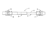
図面は自動車等のステアリング系に使用する自在軸継ぎ手付きのスプライン軸を例示する。図1及び図2において、1 はスプライン軸で、雄軸2と、この雄軸2の外周に軸心方向に摺動自在に嵌合された雌軸3と、雄軸2の外周にコーティングされた凝縮コーティング層4とを備えている。なお、雄軸2及び雌軸3の嵌合側と反対側の端部には、自在軸継ぎ手5,6のヨーク7,8が溶接等によって夫々固定されている。
【0012】
雄軸2の外周には、軸心方向のスプライン歯部9とスプライン溝部10とが周方向に交互に複数個形成されている。また雌軸3の内周には、雄軸2のスプライン歯部9とスプライン溝部10とに対応する軸心方向のスプライン溝部11とスプライン歯部12とが周方向に複数個形成されている。
【0013】
なお、雄軸2のスプライン歯部9とスプライン溝部10は、その軸心方向の略全長にわたって形成されているが、雄軸2の軸心方向の一部に設けても良い。また雌軸3のスプライン溝部11とスプライン歯部12は、自在継ぎ手6と反対側の先端部から軸心方向の中間までの一部に設けられているが、雌軸3の軸心方向の略全長に設けても良い。
【0014】
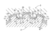
凝縮コーティング層4は、図3に示すように雄軸2の外周面の略全面、即ちスプライン歯部9の頂面14側からスプライン歯部9の周方向の両側の摺動面15側、及びスプライン溝部10の底面16側の略全体にわたって、スプライン歯部9及びスプライン溝部10の略全面に形成されており、この凝縮コーティング層4を介して雄軸2に雌軸3が軸心方向に摺動自在に嵌合されている。
【0015】
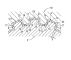
凝縮コーティング層4には、低摩擦係数のコーティング材料、例えば摩擦係数の低減に効果のある二硫化モリブデン、フッ素樹脂等が使用されている。そして、この凝縮コーティング層4は、図5に示すように、雄軸2の外周面に1次コーティング層4aを形成した後、その1次コーティング層4aを雄軸2の外周面側へと圧縮することにより凝縮されている。
【0016】
この1次コーティング層4aの圧縮凝縮は、必要以上の1次コーティング層4aを除肉して摺動荷重を低減すること、及び凝縮コーティング層4の耐久性を向上させることを目的としたものであり、例えば図4(A)(B)に示すように雌ゲージ18を使用して、1次コーティング層4aを形成した後の雄軸2をこの雌ゲージ18内に圧入することにより行われる。
【0017】
圧縮凝縮後における凝縮コーティング層4の厚さt(図4及び図6参照)は、雄軸2側のスプライン歯部9の摺動面15と、この摺動面15と周方向に相対向する雌軸3側のスプライン溝部11の摺動面19との計算上の最大隙間t1(図3参照)を基準にして、その最大隙間t1よりも僅かに大きくなっている。
【0018】
従って、圧縮凝縮後におけるコーティング層4の外径寸法は、雌軸3のスプライン溝部11の摺動面19の内径寸法よりも僅かに大であり、その後に雄軸2の外周に雌軸3を嵌合して設定摺動荷重となるまで両者を摺動させることにより、凝縮コーティング層4を介してナジミ嵌合させるようになっている。
【0019】
なお、圧縮凝縮後における凝縮コーティング層4の厚さtは、雄軸2側のスプライン歯部9の摺動面15と、この摺動面15と周方向に相対向する雌軸3側のスプライン溝部11の摺動面19との間に介在される摺動部分17が最大隙間t1よりも僅かに大となれば良く、またその他の部分では雄軸2のスプライン歯部9の頂面14側の凝縮コーティング層4と雌軸3のスプライン溝部11の底面20との間、雄軸2のスプライン溝部10の底面16側の凝縮コーティング層4と雌軸3のスプライン歯部12の頂面22との間に夫々所定の隙間ができる程度であれば良い。
【0020】
なお、スプライン軸1の雄軸2と雌軸3は、回転時にそのスプライン歯部9とスプライン溝部11との周方向の摺動面15,19側を介して正逆方向に回転力を伝達し、また軸心方向に相対的に摺動するため、雄軸2の外周のコーティング層4の全体の内、少なくとも摺動面15,19間の摺動部分17が、雄軸2のスプライン歯部9の摺動面15側に圧縮し凝縮されておれば十分である。
【0021】
このスプライン軸1を製作する場合には、雄軸2のスプライン歯部9と雌軸3のスプライン溝部11との周方向に相対向する摺動面15,19側が僅かな隙間になるように、その雄軸2及び雌軸3を加工する。そして、次に図5に示すように、雄軸2側のスプライン歯部9及びスプライン溝部10を含む外周面の全体に、二硫化モリブデン、フッ素樹脂等のコーティング材料を用いて膜厚t2(図4及び図5参照)の1次コーティング層4aのコーティングを施す。
【0022】
このときの1次コーティング層4aの膜厚t2は、凝縮後における凝縮コーティング層4の最小の厚さt以上とすれば良く、厳しい膜厚管理は必要としない。
なお、1次コーティング層4aの膜厚は、最も薄い部分が圧縮凝縮後の摺動部分17の最小の厚さt以上であり、その最小厚に若干の除肉厚分を加えた厚さであることが望ましい。
【0023】
次に図4(A)に示すように雄軸2を雌ゲージ18内に圧入して、この雌ゲージ18により雄軸2の外周面の1次コーティング層4aを雄軸2の外周面側に圧縮して凝縮する。
【0024】
このときに使用する雌ゲージ18は、図6に示すように雌軸3と同様に、雄軸2のスプライン歯部9、スプライン溝部10に対応する軸心方向のスプライン溝部23、スプライン歯部24を周方向に交互に複数個備え、そのスプライン溝部23、スプライン歯部24の内径寸法が、雄軸2のスプライン歯部9側と雌軸3のスプライン溝部11側との計算上の最大隙間t1を基準にして、雄軸2の外周面と雌ゲージ18の内周面との隙間が最大隙間t1より僅かに大きく設定されている。
【0025】
また雌ゲージ18のスプライン溝部23及びスプライン歯部24の内面には、図4(B)に示すようにその軸心方向の一端の入り口25側に外広がり状のテーパー案内面26と、このテーパー案内面26の外端側の除肉部29とが形成され、またテーパー案内面26から反対側に勾配の小さい傾斜圧縮面27と、軸心方向と平行な平行圧縮面28とが形成されている。平行圧縮面28はテーパー案内面26、傾斜圧縮面27に比較して十分長くなっている。
【0026】
このような構成の雌ゲージ18の内周に雄軸2を圧入すると、先ず雌ゲージ18の除肉部29が1次コーティング層4aの外周側を削り取って必要以上の肉を除肉する。そして、続いてテーパー案内面26がその除肉後の1次コーティング層4aの外周面側に乗り上がりながら、このテーパー案内面26及び傾斜圧縮面27により1次コーティング層4aを雄軸2の外周面側へと順次圧縮し、その後に平行圧縮面28で1次コーティング層4aを安定的に凝縮して、凝縮コーティング層4を形成する。
【0027】
このように雌ゲージ18を圧入することによって、1次コーティング層4aの外周側の必要以上の肉を容易に除肉でき、しかも凝縮前の1次コーティング層4aの膜厚を略均一にできるため、凝縮後の凝縮コーティング層4の局部的なムラ等の発生を防止できる。
【0028】
また除肉後の1次コーティング層4aを、その摺動部分17の厚さtが雌軸3のスプライン溝部11の摺動面19の内径寸法よりも僅かに大になる程度まで容易に凝縮でき、その後の凝縮コーティング層4の耐久性を向上させることができる。更に雌ゲージ18には、テーパー案内面26、傾斜圧縮面27及び平行圧縮面28があるため、圧縮凝縮に際して雄軸2の外周面の1次コーティング層4aを傷めるようなこともない。
【0029】
そして、最後に現場合わせ、その他で雄軸2と雌軸3とを嵌合し、設定摺動荷重となるまで軸心方向に相対的に摺動させながらナジミ嵌合することにより、摺動面15,19間の隙間が殆どなく、しかも摺動抵抗が低く耐久性に優れたスプライン軸1を容易且つ安価に製作できる。
【0030】
因みに、この実施形態に基づいて製作した本発明に係るスプライン軸1と、雄軸2の外周面にナイロンコーティングを施した従来のスプライン軸とを比較したところ、本発明に係るスプライン軸1は従来に比較して摺動抵抗が約1/2になり、周方向のガタが略0になった。また製作コストは従来の1/3にできた。しかも、本発明に係るスプライン軸1は、従来のナイロンコーティングを施したものでは使用できなかった高温雰囲気での使用が可能となった。
【0031】
以上、本発明の実施形態について詳述したが、本発明はこの実施形態に限定されるものではなく、趣旨を逸脱しない範囲内で種々の変更が可能である。例えば、実施形態では雄軸2の外周のスプライン歯部9及びスプライン溝部10の略全面に1次コーティング層4aを施し、その1次コーティング層4aの略全面を雌ゲージ18で雄軸2側に圧縮して凝縮するようにようにしているが、圧縮凝縮は全1次コーティング層4aの内、雄軸2のスプライン歯部9の周方向の摺動面15に対応する摺動部分17のみ、又はこの摺動部分17から周方向の一方又は両側にわたる所定範囲についてのみ行うようにしても良い。
【0032】
要するに雄軸2の外周の1次コーティング層4aの内、少なくとも回転及び摺動時に雄軸2と雌軸3とが接触する部分の1次コーティング層4aを圧縮し凝縮して凝縮コーティング層4とすれば良い。
【0033】
従って、図3に示すように雌軸3のスプライン溝部11の底面20及び/又はスプライン歯部12の頂面22との間に径方向の隙間がある場合には、雄軸2のスプライン歯部9の頂面14側及び/又はスプライン溝部10の底面16側の1次コーティング層4aは、凝縮せずにそのままにして良い。
【0034】
また雄軸2側に凝縮コーティング層4を形成する場合、その凝縮コーティング層4は雄軸2の外周面の内、少なくともスプライン歯部9の周方向の両側の摺動面15に形成すれば良く、他の部分の1次コーティング層4a、凝縮コーティング層4は省略しても良い。
【0035】
更に実施形態では、スプライン軸1を構成する雄軸2と雌軸3との内、その雄軸2の外周面に凝縮コーティング層4を形成する場合を例示しているが、雌軸3の内周面に1次コーティング層4aを形成し、その雌軸3内に雄ゲージを圧入して1次コーティング層4aを雌軸3の内周面側に圧縮し凝縮して凝縮コーティング層4を形成しても良い。
【0036】
この場合にも、雌軸3のスプライン溝部11、スプライン歯部12の内周面の略全面、又は雌軸3のスプライン溝部11の摺動面19に凝縮コーティング層4を形成しても良いし、雌軸3の内周面の略全面に1次コーティング層4aを形成して、その内の雌軸3のスプライン溝部11の摺動面19に対応する部分を凝縮コーティング層4としても良い。
【0037】
また雄軸2の外周面と雌軸3の内周面との両方に凝縮コーティング層4を設けても良し、雄軸2のスプライン歯部9にはその摺動面15の一方に、雌軸3のスプライン溝部11にはその摺動面19の他方に夫々凝縮コーティング層4を形成しても良い。
【0038】
従って、凝縮コーティング層4は、雄軸2のスプライン歯部9と雌軸3のスプライン溝部11との少なくとも周方向に相対向する摺動面15,19が凝縮コーティング層4を介して接触するように、その両者のスプライン歯部9とスプライン溝部11との摺動面15,19の内、少なくとも一方の摺動面15又は摺動面19にあれば十分である。なお、雄軸2側と雌軸3側との両方に互いに接触するように凝縮コーティング層4を形成する場合には、異なるコーティング材料を使用しても良い。
【0039】
更にスプライン軸1の他、雄軸2の外周に軸心方向のセレーション歯部とセレーション溝部とを周方向に複数個形成し、この雄軸2の外周に軸心方向に摺動自在に嵌合する雌軸3の内周に軸心方向のセレーション溝部とセレーション歯部とを周方向に複数個形成してなるセレーション式の伸縮軸の場合にも同様に実施可能である。
【0040】
従って、雄軸2はスプライン歯部9、セレーション歯部等の歯部を備え、また雌軸3はスプライン溝部11、セレーション溝部等の溝部を備えたものであれば十分である。また歯部及び/又は溝部は、その伸縮軸に要求される伸縮範囲に対応して設けておけば好く、必ずしも軸心方向の略全長にわたって設ける必要はない。
【0041】
コーティング材料は二硫化モリブデン、フッ素樹脂等が適当であるが、低摩擦係数の材料であれば、二硫化モリブデン等以外のものを使用することも可能である。また圧縮凝縮後の凝縮コーティング層4の厚さtは、当初から雄軸2と雌軸3との摺動面15,19間の最大隙間t1分に合わせておいても良い。
【0042】
雌ゲージ18は、入り口25側の除肉部29を省略して、テーパー案内面25の入り口25側端の直径を1次コーティング層4aの外径よりも大きくし、1次コーティング層4aの全てを圧縮し凝縮して凝縮コーティング層4とするように構成しても良い。1次コーティング層4aの膜厚が比較的少なく均一な場合には、このような雌ゲージ18を使用しても、圧縮凝縮後の凝縮コーティング層4の厚さのバラツキを防止できる。
【0043】
【発明の効果】
本発明では、周方向の両側に摺動面を有する軸心方向の歯部が溝部を介して周方向に複数個設けられた雄軸と、周方向の両側に雄軸の摺動面と周方向に対向する摺動面を有する軸心方向の歯部が溝部を介して周方向に複数個設けられ且つ雄軸に対して軸心方向に摺動自在に嵌合する雌軸とを備えた伸縮軸において、雄軸の外周面に低摩擦係数のコーティング材料をコーティングし、少なくとも雄軸の各摺動面に、該摺動面側のコーティング材料を圧縮して凝縮コーティング層を形成し、該凝縮コーティング層の厚さを両軸の摺動面間の最大隙間よりも僅かに大とし、両軸の各歯部の頂面と各溝部の底面との間に径方向の隙間を設けているので、伸縮軸の製作が容易で安価であり、しかも雄軸と雌軸との周方向のガタがなく、摺動荷重も低減できる利点がある。特に雌軸の内周面に凝縮コーティング層を形成する場合に比較して容易に製作できる。
【0044】
また別の本発明では、周方向の両側に摺動面を有する軸心方向の歯部が溝部を介して周方向に複数個設けられた雄軸と、周方向の両側に雄軸の摺動面と周方向に対向する摺動面を有する軸心方向の歯部が溝部を介して周方向に複数個設けられ且つ雄軸に対して軸心方向に摺動自在に嵌合する雌軸とを備えた伸縮軸において、雌軸の内周面に低摩擦係数のコーティング材料をコーティングし、少なくとも雌軸の各摺動面に、該摺動面側のコーティング材料を圧縮して凝縮コーティング層を形成し、該凝縮コーティング層の厚さを両軸の摺動面間の最大隙間よりも僅かに大とし、両軸の各歯部の頂面と各溝部の底面との間に径方向の隙間を設けているので、伸縮軸の製作が容易で安価であり、しかも雄軸と雌軸との周方向のガタがなく、摺動荷重も低減できる利点がある。
【0045】
更に本発明では、周方向の両側に摺動面を有する軸心方向の歯部が溝部を介して周方向に複数個設けられた雄軸と、周方向の両側に雄軸の摺動面と周方向に対向する摺動面を有する軸心方向の歯部が溝部を介して周方向に複数個設けられ且つ雄軸に対して軸心方向に摺動自在に嵌合する雌軸との内、雄軸の各摺動面側に凝縮コーティング層を形成するに際し、雄軸の外周面に低摩擦係数のコーティング材料をコーティングして1次コーティング層を形成し、次に雄軸をゲージに圧入して、該ゲージの入り口側の除去部で1次コーティング層の必要以上の肉を除去しながら、少なくとも雄軸の各摺動面側の1次コーティング層を、両軸の摺動面側の最大隙間よりも僅かに大きな厚さまでゲージにより圧縮し凝縮して凝縮コーティング層を形成し、次に両軸を嵌合して設定摺動荷重となるまで該両軸を摺動させるので、伸縮軸の製作が容易で安価であり、しかも雄軸と雌軸との周方向のガタがなく、摺動荷重も低減できる利点がある。
【0046】
また本発明では、周方向の両側に摺動面を有する軸心方向の歯部が溝部を介して周方向に複数個設けられた雄軸と、周方向の両側に雄軸の摺動面と周方向に対向する摺動面を有する軸心方向の歯部が溝部を介して周方向に複数個設けられ且つ雄軸に対して軸心方向に摺動自在に嵌合する雌軸との内、雌軸の各摺動面側に凝縮コーティング層を形成するに際し、雌軸の外周面に低摩擦係数のコーティング材料をコーティングして1次コーティング層を形成し、次に雌軸をゲージに圧入して、該ゲージの入り口側の除去部で1次コーティング層の必要以上の肉を除去しながら、少なくとも雌軸の各摺動面側の1次コーティング層を、両軸の摺動面側の最大隙間よりも僅かに大きな厚さまでゲージにより圧縮し凝縮して凝縮コーティング層を形成し、次に両軸を嵌合して設定摺動荷重となるまで該両軸を摺動させる伸縮軸の製作が容易で安価であり、しかも雄軸と雌軸との周方向のガタがなく、摺動荷重も低減できる利点がある。
【0047】
しかも入り口側に形成された外広がり状のテーパー案内面を有する雌ゲージを使用するため、雄軸の外周のコーティング層を傷めることなく容易に圧縮し凝縮できる。
【図面の簡単な説明】
【図1】本発明の一実施形態を示すスプライン軸の正面図である。
【図2】本発明の一実施形態を示すスプライン軸の拡大断面図である。
【図3】本発明の一実施形態を示すスプライン軸の要部の拡大断面図である。
【図4】(A)は本発明の一実施形態を示す圧縮凝縮工程の説明図、(B)は(A)の部分拡大図である。
【図5】本発明の一実施形態を示す1次コーティング状態の拡大断面図である。
【図6】本発明の一実施形態を示す圧縮凝縮工程の拡大断面図である。
【符号の説明】
1 スプライン軸
2 雄軸
3 雌軸
4 凝縮コーティング層
4a 1次コーティング層
9,12 スプライン歯部
10,11 スプライン溝部
15,19 摺動面
18 雌ゲージ
26 テーパー案内面[0001]
BACKGROUND OF THE INVENTION
The present invention relates to a telescopic shaft such as a spline shaft used in an automobile steering system and a coating layer forming method for the telescopic shaft.
[0002]
[Prior art]
An automotive steering system includes a male shaft having a plurality of axial spline teeth on the outer periphery in the circumferential direction, and a plurality of axial spline grooves corresponding to the male spline teeth in the circumferential direction. There is one that employs a telescopic shaft such as a spline shaft that is provided with a female shaft that is provided individually and is slidably fitted in the axial direction on the outer periphery of the male shaft.
[0003]
In this type of spline shaft, the sliding load (sliding resistance) and the play in the rotational direction are in a contradictory relationship. That is, if the backlash in the rotational direction is reduced, the sliding load increases, and conversely, if the sliding load is lightened, the backlash in the rotational direction increases. Therefore, it is difficult to achieve both the characteristics of the sliding load and the play in the rotational direction.
[0004]
Therefore, conventionally, after forming a nylon coating layer on the outer peripheral surface of the male shaft for the purpose of reducing the friction coefficient, the sliding surface side of this nylon coating layer is changed to the inner diameter of the sliding surface on the inner peripheral side of the female shaft. The coating layer is formed by cutting together or coating the outer peripheral surface of the male shaft with a material that is effective in reducing the friction coefficient such as molybdenum disulfide or fluororesin while controlling the film thickness for the purpose of loosening. Thus, a method is adopted in which the backlash in the rotational direction of the male shaft and the female shaft is reduced to achieve both characteristics at a relatively high level.
[0005]
[Problems to be solved by the invention]
In the conventional method of forming the nylon coating layer on the outer peripheral surface of the male shaft and then cutting the sliding surface side of the nylon coating layer, a cutting step of cutting the sliding surface side after forming the coating layer is required. Therefore, the cutting is cumbersome and very expensive, and the coating layer is simply cut, so that there is a problem in durability of the sliding surface.
[0006]
In addition, coating the outer peripheral surface of the male shaft with molybdenum disulfide, fluororesin, etc. while controlling the film thickness is difficult and costly, and the inner diameter of the sliding surface on the inner peripheral side of the female shaft Due to the variation in dimensions, the backlash is not stable, and the surface of the coating layer is soft.
[0007]
SUMMARY OF THE INVENTION In view of such conventional problems, the present invention is easy to manufacture and inexpensive, has no backlash in the rotational direction of the male shaft and the female shaft, and can reduce sliding load, and a coating layer for the telescopic shaft and the telescopic shaft. An object is to provide a forming method.
[0008]
[Means for Solving the Problems]
The telescopic shaft according to the present invention includes a male shaft in which a plurality of axial teeth having sliding surfaces on both sides in the circumferential direction are provided in the circumferential direction via grooves, and the male shaft on both sides in the circumferential direction. A plurality of axial teeth having a sliding surface facing the sliding surface in the circumferential direction are provided in the circumferential direction via a groove, and are slidably fitted in the axial direction with respect to the male shaft. A telescopic shaft provided with a female shaft that coats the outer peripheral surface of the male shaft with a low friction coefficient coating material, and at least the sliding surface of the male shaft is coated with the coating material on the sliding surface side. The condensed coating layer is formed by compression , and the thickness of the condensed coating layer is set to be slightly larger than the maximum gap between the sliding surfaces of the two shafts, and the top surfaces of the tooth portions of the two shafts and the A radial gap is provided between the bottom surface of each groove portion .
The telescopic shaft according to another aspect of the present invention includes a male shaft in which a plurality of axial teeth having sliding surfaces on both sides in the circumferential direction are provided in the circumferential direction via grooves, and the male shaft on both sides in the circumferential direction. A plurality of axial teeth having a sliding surface facing the sliding surface of the male shaft in the circumferential direction are provided in the circumferential direction via a groove and are slidable axially with respect to the male shaft. A telescopic shaft having a female shaft fitted to the inner surface of the female shaft, a coating material having a low friction coefficient is coated on the inner peripheral surface of the female shaft, and at least the sliding surfaces of the female shaft are arranged on the sliding surface side. The coating material is compressed to form a condensed coating layer, and the thickness of the condensed coating layer is set to be slightly larger than the maximum gap between the sliding surfaces of the two shafts. A radial gap is provided between the top surface and the bottom surface of each groove.
The method for forming a coating layer for a telescopic shaft according to the present invention includes a male shaft in which a plurality of axial teeth having sliding surfaces on both sides in the circumferential direction are provided in the circumferential direction via grooves, and both sides in the circumferential direction. A plurality of axial teeth having a sliding surface facing the sliding surface of the male shaft in the circumferential direction are provided in the circumferential direction via a groove portion and slid in the axial direction with respect to the male shaft. When a condensation coating layer is formed on each sliding surface side of the male shaft among the female shafts that are movably fitted, the outer peripheral surface of the male shaft is coated with a coating material having a low coefficient of friction. A coating layer is formed, and then the male shaft is press-fitted into the gauge, and at least the slides of the male shaft are removed while removing unnecessary meat of the primary coating layer at the removal portion on the inlet side of the gauge. The primary coating layer on the moving surface side is the maximum on the sliding surface side of both shafts. Compressed and condensed with the gauge to a thickness slightly larger than the gap to form the condensed coating layer, and then the shafts are slid until the shafts are fitted and set sliding load is reached. is there.
The method for forming a coating layer for a telescopic shaft according to the present invention includes a male shaft provided with a plurality of axial teeth having circumferential sliding surfaces on both sides in the circumferential direction, and a circumferential direction. A plurality of axial teeth having a sliding surface facing the sliding surface of the male shaft in the circumferential direction on both sides are provided in the circumferential direction via a groove, and in the axial direction with respect to the male shaft. When forming the condensation coating layer on each sliding surface side of the female shaft among the female shafts that are slidably fitted, the outer peripheral surface of the female shaft is coated with a coating material having a low friction coefficient. Forming the next coating layer, and then press-fitting the female shaft into the gauge, and removing unnecessary meat of the primary coating layer at the removal portion on the inlet side of the gauge, while at least each of the female shafts The primary coating layer on the sliding surface side is formed on the sliding surface side of both shafts. Compressed and condensed by the gauge to a thickness slightly larger than a large gap to form the condensed coating layer, and then the shafts are fitted and slid until the set sliding load is reached. It is.
[0009]
The method for forming a coating layer for a telescopic shaft according to the present invention includes a male shaft having a plurality of teeth on the outer periphery in the circumferential direction, and a plurality of grooves on the inner periphery corresponding to the teeth in the circumferential direction. When forming the condensation coating layer on the sliding surface side of at least one of the female shafts slidably fitted in the axial direction with respect to the male shaft, the sliding of the one shaft is performed. A coating material having a low coefficient of friction is coated on the surface side to form a primary coating layer, and then one of the shafts is the maximum on the sliding surface side opposite to the circumferential direction of the male shaft and the female shaft. It press-fits into a gauge set at a gap slightly larger than the gap, and the primary coating layer is compressed and condensed on the one shaft side by the gauge.
[0010]
DETAILED DESCRIPTION OF THE INVENTION
Hereinafter, embodiments of the present invention will be described in detail with reference to the drawings.
[0011]
The drawing illustrates a spline shaft with a universal shaft joint used in a steering system of an automobile or the like. 1 and 2,
[0012]
A plurality of
[0013]
In addition, although the
[0014]
As shown in FIG. 3, the condensation coating layer 4 is formed on substantially the entire outer peripheral surface of the
[0015]
For the condensation coating layer 4, a coating material having a low friction coefficient, for example, molybdenum disulfide, fluorine resin, or the like that is effective in reducing the friction coefficient is used. Then, the condensed coating layer 4, as shown in FIG. 5, after forming the
[0016]
The purpose of the compression condensation of the
[0017]
The thickness t (see FIGS. 4 and 6) of the condensation coating layer 4 after compression condensation is opposite to the sliding
[0018]
Therefore, the outer diameter dimension of the coating layer 4 after compression condensation is slightly larger than the inner diameter dimension of the sliding
[0019]
The thickness t of the condensed coating layer 4 after compression condensation is determined by the sliding
[0020]
The
[0021]
When the
[0022]
The film thickness t2 of the
Note that the thickness of the
[0023]
Next, as shown in FIG. 4A, the
[0024]
The
[0025]
Further, on the inner surface of the
[0026]
When the
[0027]
By press-fitting the
[0028]
Further, the
[0029]
Finally, the sliding surface is obtained by fitting the
[0030]
Incidentally, when the
[0031]
As mentioned above, although embodiment of this invention was explained in full detail, this invention is not limited to this embodiment, A various change is possible within the range which does not deviate from the meaning. For example, in the embodiment, the
[0032]
In short, the
[0033]
Therefore, when there is a radial gap between the
[0034]
Further, when the condensation coating layer 4 is formed on the
[0035]
Further, in the embodiment, the case where the condensation coating layer 4 is formed on the outer peripheral surface of the
[0036]
Also in this case, the condensation coating layer 4 may be formed on substantially the entire inner peripheral surface of the
[0037]
The condensation coating layer 4 may be provided on both the outer peripheral surface of the
[0038]
Therefore, the condensation coating layer 4 is configured such that the sliding
[0039]
In addition to the
[0040]
Therefore, it is sufficient that the
[0041]
As the coating material, molybdenum disulfide, fluororesin, or the like is appropriate, but it is also possible to use materials other than molybdenum disulfide as long as the material has a low friction coefficient. In addition, the thickness t of the condensed coating layer 4 after compression condensation may be adjusted to the maximum gap t1 between the sliding
[0042]
The
[0043]
【The invention's effect】
In the present invention, a male shaft in which a plurality of axial teeth having sliding surfaces on both sides in the circumferential direction are provided in the circumferential direction via grooves, and a sliding surface of the male shaft and a circumferential surface on both sides in the circumferential direction. A plurality of teeth in the axial direction having sliding surfaces opposed to each other are provided in the circumferential direction via the groove, and a female shaft is fitted to the male shaft so as to be slidable in the axial direction. In the telescopic shaft, the outer peripheral surface of the male shaft is coated with a low friction coefficient coating material, and at least the sliding surface of the male shaft is compressed with the coating material on the sliding surface side to form a condensed coating layer , The thickness of the condensation coating layer is slightly larger than the maximum gap between the sliding surfaces of both shafts, and a radial gap is provided between the top surface of each tooth portion and the bottom surface of each groove portion of both shafts. since the fabrication of the telescopic shaft is easy and inexpensive, yet there is no circumferential backlash between the male shaft and the female shaft, in also reducing sliding load There is an advantage in that. In particular, it can be easily manufactured as compared with the case where the condensation coating layer is formed on the inner peripheral surface of the female shaft.
[0044]
In another aspect of the present invention, a male shaft in which a plurality of axial teeth having a sliding surface on both sides in the circumferential direction are provided in the circumferential direction via a groove portion, and a sliding of the male shaft on both sides in the circumferential direction. A plurality of axial teeth having a sliding surface facing the surface in the circumferential direction, and a female shaft that is provided in the circumferential direction via the groove and is slidably fitted to the male shaft in the axial direction. A coating material having a low friction coefficient is coated on the inner peripheral surface of the female shaft, and at least the sliding material on the sliding surface side is compressed on each sliding surface of the female shaft to form a condensation coating layer. The thickness of the condensation coating layer is slightly larger than the maximum gap between the sliding surfaces of both shafts, and the radial gap between the top surface of each tooth portion of each shaft and the bottom surface of each groove portion since the is provided, is easy to manufacture the telescopic shaft are inexpensive, yet there is no circumferential backlash between the male shaft and the female shaft, sliding load There is an advantage that can be reduced.
[0045]
Further, in the present invention, a male shaft in which a plurality of axial teeth having a sliding surface on both sides in the circumferential direction are provided in the circumferential direction via the groove, and a sliding surface of the male shaft on both sides in the circumferential direction. A plurality of teeth in the axial direction having sliding surfaces facing in the circumferential direction are provided in the circumferential direction via the groove, and the female shaft is slidably fitted in the axial direction with respect to the male axis. When a condensation coating layer is formed on each sliding surface side of the male shaft, a coating material having a low friction coefficient is coated on the outer peripheral surface of the male shaft to form a primary coating layer, and then the male shaft is press-fitted into the gauge. Then, while removing the unnecessary thickness of the primary coating layer at the removal portion on the entrance side of the gauge, at least the primary coating layer on each sliding surface side of the male shaft is placed on the sliding surface side of both shafts. even than the maximum clearance compressed by slightly gauge to a larger thickness condensed to form a condensed coating layer Since the next slide both said shaft until engaging and set sliding load both axes, is easy to manufacture the telescopic shaft are inexpensive, yet there is no circumferential backlash between the male shaft and the female shaft There is an advantage that the sliding load can be reduced.
[0046]
Further, in the present invention, a male shaft in which a plurality of axial teeth having a sliding surface on both sides in the circumferential direction are provided in the circumferential direction via the groove, and a sliding surface of the male shaft on both sides in the circumferential direction. A plurality of teeth in the axial direction having sliding surfaces facing in the circumferential direction are provided in the circumferential direction via the groove, and the female shaft is slidably fitted in the axial direction with respect to the male axis. When forming the condensation coating layer on each sliding surface side of the female shaft, the outer coating surface of the female shaft is coated with a low friction coefficient coating material to form the primary coating layer, and then the female shaft is press-fitted into the gauge. Then, at least the primary coating layer on each sliding surface side of the female shaft is placed on the sliding surface side of both shafts while removing the unnecessary thickness of the primary coating layer at the removal portion on the entrance side of the gauge. Compressed with a gauge to a thickness slightly larger than the maximum gap and condensed to form a condensed coating layer Then fabrication of the telescopic shaft for sliding the both said shaft until engaging and set sliding load both axes is easy and inexpensive, yet there is no circumferential backlash between the male shaft and the female shaft, sliding There is an advantage that dynamic load can be reduced.
[0047]
Moreover, since a female gauge having an outwardly extending tapered guide surface formed on the entrance side is used, it can be easily compressed and condensed without damaging the coating layer on the outer periphery of the male shaft.
[Brief description of the drawings]
FIG. 1 is a front view of a spline shaft showing an embodiment of the present invention.
FIG. 2 is an enlarged sectional view of a spline shaft showing an embodiment of the present invention.
FIG. 3 is an enlarged cross-sectional view of a main part of a spline shaft showing an embodiment of the present invention.
4A is an explanatory view of a compression condensation process showing an embodiment of the present invention, and FIG. 4B is a partially enlarged view of FIG. 4A.
FIG. 5 is an enlarged cross-sectional view of a primary coating state showing an embodiment of the present invention.
FIG. 6 is an enlarged cross-sectional view of a compression condensation process showing an embodiment of the present invention.
[Explanation of symbols]
1
Claims (5)
Priority Applications (1)
| Application Number | Priority Date | Filing Date | Title |
|---|---|---|---|
| JP2002085670A JP4045112B2 (en) | 2002-03-26 | 2002-03-26 | Telescopic shaft and method for forming coating layer of telescopic shaft |
Applications Claiming Priority (1)
| Application Number | Priority Date | Filing Date | Title |
|---|---|---|---|
| JP2002085670A JP4045112B2 (en) | 2002-03-26 | 2002-03-26 | Telescopic shaft and method for forming coating layer of telescopic shaft |
Publications (3)
| Publication Number | Publication Date |
|---|---|
| JP2003278738A JP2003278738A (en) | 2003-10-02 |
| JP2003278738A5 JP2003278738A5 (en) | 2004-12-09 |
| JP4045112B2 true JP4045112B2 (en) | 2008-02-13 |
Family
ID=29232546
Family Applications (1)
| Application Number | Title | Priority Date | Filing Date |
|---|---|---|---|
| JP2002085670A Expired - Fee Related JP4045112B2 (en) | 2002-03-26 | 2002-03-26 | Telescopic shaft and method for forming coating layer of telescopic shaft |
Country Status (1)
| Country | Link |
|---|---|
| JP (1) | JP4045112B2 (en) |
Cited By (1)
| Publication number | Priority date | Publication date | Assignee | Title |
|---|---|---|---|---|
| WO2012128213A1 (en) | 2011-03-18 | 2012-09-27 | 株式会社ジェイテクト | Manufacturing method for drive shaft and vehicle steering device |
Families Citing this family (11)
| Publication number | Priority date | Publication date | Assignee | Title |
|---|---|---|---|---|
| JP5104332B2 (en) * | 2008-01-18 | 2012-12-19 | 日本精工株式会社 | Telescopic shaft manufacturing method and telescopic shaft manufactured by this manufacturing method |
| JP5453012B2 (en) * | 2009-08-07 | 2014-03-26 | 株式会社ジェイテクト | Spline telescopic shaft manufacturing method |
| JP2011038560A (en) * | 2009-08-07 | 2011-02-24 | Jtekt Corp | Spline telescopic shaft, method of manufacturing the same, and vehicle steering apparatus |
| KR101143494B1 (en) * | 2009-11-30 | 2012-05-08 | 정운규 | The manufacturing method of serration shaft |
| JP5510602B2 (en) * | 2010-10-11 | 2014-06-04 | 日本精工株式会社 | Telescopic shaft manufacturing method and telescopic shaft manufactured by this manufacturing method |
| JP5408194B2 (en) * | 2010-10-11 | 2014-02-05 | 日本精工株式会社 | Telescopic shaft manufacturing method and telescopic shaft manufactured by this manufacturing method |
| JP6025172B2 (en) * | 2013-01-25 | 2016-11-16 | 株式会社ジェイテクト | Spline telescopic shaft manufacturing method |
| JP6132154B2 (en) * | 2013-07-18 | 2017-05-24 | 株式会社ジェイテクト | Sliding shaft and steering device |
| JP5967627B2 (en) * | 2014-07-31 | 2016-08-10 | 株式会社ジェイテクト | Spline telescopic shaft manufacturing method |
| US9416815B2 (en) * | 2014-10-01 | 2016-08-16 | GM Global Technology Operations LLC | Driveshaft with two-stage stiffness |
| KR101979737B1 (en) * | 2017-09-15 | 2019-08-28 | 최상기 | Spline shaft and spline manufacturing method |
-
2002
- 2002-03-26 JP JP2002085670A patent/JP4045112B2/en not_active Expired - Fee Related
Cited By (1)
| Publication number | Priority date | Publication date | Assignee | Title |
|---|---|---|---|---|
| WO2012128213A1 (en) | 2011-03-18 | 2012-09-27 | 株式会社ジェイテクト | Manufacturing method for drive shaft and vehicle steering device |
Also Published As
| Publication number | Publication date |
|---|---|
| JP2003278738A (en) | 2003-10-02 |
Similar Documents
| Publication | Publication Date | Title |
|---|---|---|
| JP4045112B2 (en) | Telescopic shaft and method for forming coating layer of telescopic shaft | |
| US9039286B2 (en) | Bearing device for a wheel | |
| WO2007145019A1 (en) | Constant velocity universal joint | |
| JPH09217605A (en) | Camshaft manufacturing method and camshaft | |
| KR20070016977A (en) | Synchronizer for Transmission | |
| CN101611233A (en) | Constant velocity universal joint | |
| WO2002102608A1 (en) | Bearing device for drive wheel and method of manufacturing the bearing device | |
| JP2002089572A (en) | Bearing device | |
| JP4302730B2 (en) | Wheel bearing device | |
| JP2008162359A5 (en) | ||
| US6699340B2 (en) | Method for producing driving shaft with male and female shaft member | |
| JP2003278738A5 (en) | ||
| JPH11108070A (en) | Shaft member fitting structure and fitting method | |
| CN2322352Y (en) | Elastic gap-allowable ring for holding rolling-bearing on axle | |
| US20200158182A1 (en) | Device for connecting a toothing part to a shaft for conjoint rotation with the latter, method for producing such a device, and angular gear | |
| JP5410265B2 (en) | Wheel bearing device | |
| JP5349912B2 (en) | Wheel bearing device and separation method thereof | |
| JP4613462B2 (en) | Axle bearing device | |
| JP4037238B2 (en) | Gearbox synchronizer | |
| JP5823437B2 (en) | Manufacturing method of wheel bearing device | |
| JP5301128B2 (en) | Wheel bearing device | |
| JPH04136522A (en) | Manufacturing of power transmission shaft | |
| JP5179101B2 (en) | Wheel bearing device | |
| JP3305481B2 (en) | Connection structure between fiber reinforced resin cylindrical tube and metal end member | |
| JP2022149828A (en) | Wheel bearing device |
Legal Events
| Date | Code | Title | Description |
|---|---|---|---|
| A131 | Notification of reasons for refusal |
Free format text: JAPANESE INTERMEDIATE CODE: A131 Effective date: 20061107 |
|
| A977 | Report on retrieval |
Free format text: JAPANESE INTERMEDIATE CODE: A971007 Effective date: 20061110 |
|
| A521 | Request for written amendment filed |
Free format text: JAPANESE INTERMEDIATE CODE: A523 Effective date: 20061221 |
|
| TRDD | Decision of grant or rejection written | ||
| A01 | Written decision to grant a patent or to grant a registration (utility model) |
Free format text: JAPANESE INTERMEDIATE CODE: A01 Effective date: 20071106 |
|
| A61 | First payment of annual fees (during grant procedure) |
Free format text: JAPANESE INTERMEDIATE CODE: A61 Effective date: 20071119 |
|
| R150 | Certificate of patent or registration of utility model |
Ref document number: 4045112 Country of ref document: JP Free format text: JAPANESE INTERMEDIATE CODE: R150 Free format text: JAPANESE INTERMEDIATE CODE: R150 |
|
| FPAY | Renewal fee payment (event date is renewal date of database) |
Free format text: PAYMENT UNTIL: 20101122 Year of fee payment: 3 |
|
| FPAY | Renewal fee payment (event date is renewal date of database) |
Free format text: PAYMENT UNTIL: 20101122 Year of fee payment: 3 |
|
| FPAY | Renewal fee payment (event date is renewal date of database) |
Free format text: PAYMENT UNTIL: 20101122 Year of fee payment: 3 |
|
| FPAY | Renewal fee payment (event date is renewal date of database) |
Free format text: PAYMENT UNTIL: 20111122 Year of fee payment: 4 |
|
| R250 | Receipt of annual fees |
Free format text: JAPANESE INTERMEDIATE CODE: R250 |
|
| FPAY | Renewal fee payment (event date is renewal date of database) |
Free format text: PAYMENT UNTIL: 20111122 Year of fee payment: 4 |
|
| FPAY | Renewal fee payment (event date is renewal date of database) |
Free format text: PAYMENT UNTIL: 20121122 Year of fee payment: 5 |
|
| R250 | Receipt of annual fees |
Free format text: JAPANESE INTERMEDIATE CODE: R250 |
|
| FPAY | Renewal fee payment (event date is renewal date of database) |
Free format text: PAYMENT UNTIL: 20121122 Year of fee payment: 5 |
|
| FPAY | Renewal fee payment (event date is renewal date of database) |
Free format text: PAYMENT UNTIL: 20131122 Year of fee payment: 6 |
|
| R250 | Receipt of annual fees |
Free format text: JAPANESE INTERMEDIATE CODE: R250 |
|
| R250 | Receipt of annual fees |
Free format text: JAPANESE INTERMEDIATE CODE: R250 |
|
| R250 | Receipt of annual fees |
Free format text: JAPANESE INTERMEDIATE CODE: R250 |
|
| R250 | Receipt of annual fees |
Free format text: JAPANESE INTERMEDIATE CODE: R250 |
|
| R250 | Receipt of annual fees |
Free format text: JAPANESE INTERMEDIATE CODE: R250 |
|
| R250 | Receipt of annual fees |
Free format text: JAPANESE INTERMEDIATE CODE: R250 |
|
| R250 | Receipt of annual fees |
Free format text: JAPANESE INTERMEDIATE CODE: R250 |
|
| R250 | Receipt of annual fees |
Free format text: JAPANESE INTERMEDIATE CODE: R250 |
|
| R250 | Receipt of annual fees |
Free format text: JAPANESE INTERMEDIATE CODE: R250 |
|
| LAPS | Cancellation because of no payment of annual fees |