JP4043173B2 - Cylinder cushion structure - Google Patents
Cylinder cushion structure Download PDFInfo
- Publication number
- JP4043173B2 JP4043173B2 JP2000213786A JP2000213786A JP4043173B2 JP 4043173 B2 JP4043173 B2 JP 4043173B2 JP 2000213786 A JP2000213786 A JP 2000213786A JP 2000213786 A JP2000213786 A JP 2000213786A JP 4043173 B2 JP4043173 B2 JP 4043173B2
- Authority
- JP
- Japan
- Prior art keywords
- cushion
- cylinder
- piston
- seal
- cushion seal
- Prior art date
- Legal status (The legal status is an assumption and is not a legal conclusion. Google has not performed a legal analysis and makes no representation as to the accuracy of the status listed.)
- Expired - Fee Related
Links
Images


Classifications
-
- F—MECHANICAL ENGINEERING; LIGHTING; HEATING; WEAPONS; BLASTING
- F16—ENGINEERING ELEMENTS AND UNITS; GENERAL MEASURES FOR PRODUCING AND MAINTAINING EFFECTIVE FUNCTIONING OF MACHINES OR INSTALLATIONS; THERMAL INSULATION IN GENERAL
- F16J—PISTONS; CYLINDERS; SEALINGS
- F16J15/00—Sealings
- F16J15/16—Sealings between relatively-moving surfaces
-
- F—MECHANICAL ENGINEERING; LIGHTING; HEATING; WEAPONS; BLASTING
- F15—FLUID-PRESSURE ACTUATORS; HYDRAULICS OR PNEUMATICS IN GENERAL
- F15B—SYSTEMS ACTING BY MEANS OF FLUIDS IN GENERAL; FLUID-PRESSURE ACTUATORS, e.g. SERVOMOTORS; DETAILS OF FLUID-PRESSURE SYSTEMS, NOT OTHERWISE PROVIDED FOR
- F15B15/00—Fluid-actuated devices for displacing a member from one position to another; Gearing associated therewith
- F15B15/20—Other details, e.g. assembly with regulating devices
- F15B15/22—Other details, e.g. assembly with regulating devices for accelerating or decelerating the stroke
- F15B15/222—Other details, e.g. assembly with regulating devices for accelerating or decelerating the stroke having a piston with a piston extension or piston recess which throttles the main fluid outlet as the piston approaches its end position
Description
【0001】
【発明の属する技術分野】
この発明は、ピストンのストロークエンドでの衝撃を緩和するためのシリンダのクッション構造に関する。
【0002】
【従来の技術】
シリンダのクッション装置として、図3、図4に示すものが従来から知られているが、その構造は次のとおりである。
シリンダチューブ1にピストン2を摺動自在に組み込むとともに、このピストン2にピストンロッド3を設けている。そして、このピストン2によって、シリンダチューブ1内を、シリンダ室4と5に区画している。
しかも、上記ピストンロッド3であってピストン2と隣接する位置に、クッションリング6を固定している。このクッションリング6には、ピストン2とは反対端からピストン側に向かって徐々に浅くなるスリット7を形成している。
【0003】
また、上記シリンダチューブ1の端部には、シリンダヘッド8をはめ着けているが、このシリンダヘッド8の内周には軸受け9を設けている。そして、上記ピストンロッド3は、この軸受け9に摺動自在に支持されて、シリンダヘッド8から外方に突出する。
なお、図中符号10は軸受け9よりも内側に設けたシールである。
【0004】
上記のようにしたシリンダヘッド8の内端には、ホルダー11を固定するとともに、このホルダー11の内周には、シリンダヘッド8側から順にカラー12および金属製のクッションシール13をはめている。
上記カラー12は、ホルダー11に圧入するとともに、一端をシリンダヘッド8の内端にぴったりと接触させている。また、カラー12の他端、すなわちクッションシール13との対向面に切欠き14を形成し、カラー12の他端にクッションシール13が当接したときにオリフィスを構成するようにしている。なお、クッションシール13がカラー12から離れることによって、この切欠き14が解放され、オリフィスとしての機能はなくなる。
【0005】
一方、クッションシール13は、上記カラー12とホルダー11の内端に形成したストッパー15との間を移動可能にしている。このようにしたクッションシール13は、ホルダー11との間で、図4に示すように多少のすき間16を保つとともに、ピストン2がストロークエンド部分に到達したとき、クッションリング6が進入できる内径を保っている。
また、上記ホルダー11には、自由流通路17を形成しているが、この自由流通路17は、クッションシール13がストッパー15に当接しているとき、カラー12とクッションシール13との間を介して、シリンダ室4とシリンダポート18とを自由流れの状態で連通させる。
【0006】
上記のようにして各部材を組み付けているが、実際には次のような部分にかん合すき間ができてしまう。まず、クッションリング6は、ピストンロッド3との間にその組み付け上必要とされるかん合すき間がある。また、軸受け9とピストンロッド3との間にもかん合すき間が生じてしまう。さらに、シリンダチューブ1とピストン2との間にもかん合すき間が生じる。
上記のようなかん合すき間は、各部材の軸心をずらす原因となる。そして、上記した各かん合すき間が総合化されてピストンロッド3が偏心するが、その偏心を吸収するために、クッションシール13が径方向にある程度動けるようにしている。
【0007】
もし、クッションシール13が径方向に一切動けなければ、上記したかん合すき間が総合化されてピストンロッド3が偏心したとき、ピストンのストロークエンド部分で、クッションリング6がクッションシール13に進入できなくなる。
しかし、上記のようにクッションシール13が径方向に動ければ、ピストンロッド3の偏心を吸収することができる。
【0008】
今、ピストン2が図3の状態から、矢印19方向に移動すると、シリンダ室4内の作動流体は、クッションシール13とカラー12の内側を通ってシリンダポート18から排出される。そして、クッションリング6がクッションシール13に進入しようとすると、そのときの流体圧でクッションシール13がカラー12に押し付けられる。この状態では、自由流通路17は、クッションシール13の外周に形成したすき間16を介して切欠き14に連通することになる。
【0009】
上記の状態から図4に示すように、クッションリング6がクッションシール13内に進入すると、シリンダ室4とシリンダポート18とは、次の2つの通路を介して連通することになる。
その一つは、クッションシール13とクッションリング6に形成したスリット7との間を通過する通路と、もう一つは、前記すき間16および切欠き14からなるオリフィスを通過する通路とである。
いずれにしても、上記2つの通路は、その流路抵抗が大きいので、その抵抗によってシリンダ室4の圧力が上昇し、その上昇した圧力によってピストン2の移動速度を緩和させ、クッション効果を発揮させる。
【0010】
また、前記したように組み付け上のかん合すき間は、それが総合化されるとピストンロッド3が偏心するが、その偏心を吸収するために、クッションシール13が径方向にある程度動けるようにしている。そのために、クッションリング6がクッションシール13に進入するとき、それらの軸心が完全に一致していないことが多くなる。
【0011】
しかし、クッションリング6とクッションシール13との軸心が多少ずれていても、クッションシール13ががたつきながら、徐々にクッションリング6になじんでいき、最終的には両者の軸心がぴったりと一致するようになる。この原理は、棒をきっちりとした穴に入れるときに、棒を少しがたつかせながら穴に押し込むのににている。
【0012】
一方、ピストン2を上記矢印19とは反対方向に移動させるときには、シリンダポート18から圧力流体を供給する。このようにシリンダポート18から圧力流体を供給すると、その圧力作用で、クッションシール13がストッパー15側まで移動する。クッションシール13がこのように移動すれば、切欠き14からなるオリフィスが解放されるとともに、カラー12とクッションシール13との間および自由流通路17を介して、シリンダ室4とシリンダポート18とが、直接連通することになる。
したがって、シリンダポート18から供給された圧力流体は、カラー12とクッションシール13との間および自由流通路17を介してシリンダ室4に供給されるとともに、ピストン2を上記矢印19とは反対方向に移動させる。
【0013】
【発明が解決しようとする課題】
上記のようにした従来のクッション構造では、クッションリング6とクッションシール13との軸心がずれているにもかかわらず、クッションリング6がクッションシール13内に進入すると、クッションリング6の進入方向先端が、クッションシール13の開口端に衝突してしまう。このように両者が衝突すると、衝突音が発生するが、この衝突音は、シリンダが故障しているのではないかといった不安感をオペレータ等に抱かせてしまう。また、オペレータ等に不安感を抱かせるだけでなく、衝突が頻繁になれば、実際にも、クッションシール13が欠けたりして、故障の原因にもなってしまう。
また、上記の衝突音は、クッションシールのがたつきと共振して、かなり高い周波数の音になってしまい、その音自体が耳障りになるといった問題もあった。
【0014】
さらに、軸心をずらしたクッションリング6とクッションシール13との軸心がずれているときには、クッションリング6が、クッションシール13をがたつかせながら徐々になじませるようにして進入していくので、そのがたつき状況によっては、クッションシール13が偏摩耗し、そのシール機能を損なわせるという問題があった。
【0015】
【課題を解決するための手段】
この発明は、シリンダチューブにピストンを摺動自在に設けるとともに、シリンダチューブの端部にシリンダヘッドを設け、このシリンダヘッドからピストンに設けたピストンロッドを外方に突出させ、シリンダチューブに形成したシリンダポートから圧力流体を供給したり、あるいはそこから圧力流体を排出することによって、ピストンを往復運動させる一方、上記ピストンロッド側にクッションリングを設けるとともに、上記シリンダヘッド内端にはホルダーを固定し、このホルダーの内周に、軸方向に移動可能にした金属製のクッションシールを設け、クッション機能発揮時に、上記クッションシールにクッションリングが進入する構成にしたシリンダのクッション構造を前提にする。
【0016】
上記の構造を前提にしつつ、第1の発明は、上記ホルダーの内周には、そのピストン側の端部にストッパーを形成するとともに、このストッパーと対向するシリンダヘッド側には上記ホルダーとは別体からなるカラーを設け、上記ストッパーとカラーとの間に上記クッションシールを位置させる一方、このクッションシールと上記ストッパーとの間にはスペーサーを設け、上記カラーとストッパーとの間で上記クッションシールおよびスペーサを軸方向に移動可能にしてなり、かつ、このスペーサーの内径をクッションシールの内径よりも大きくした点に特徴を有する。
第2の発明は、クッション機能を発揮する方向と反対方向にピストンが移動しているとき、そのピストンの移動方向にクッションシールが移動するとともに、その移動にともなって、シリンダポートとシリンダ室とを連通させる自由流通路をホルダーに形成した点に特徴を有する。
【0017】
第3の発明は、上記カラーの内端であってクッションシールとの対向面にオリフィスを構成する切欠きを設ける一方、上記自由流通路はホルダーの内周に形成してなり、クッションシールおよびスペーサーが、クッション機能を発揮する方向と反対方向に移動したとき、上記切欠きと自由流通路とが連通する構成にした点に特徴を有する。
【0018】
【発明の実施の形態】
図1、図2に示したシリンダのクッション構造は、次のとおりである。
シリンダチューブ21にピストン22を摺動自在に組み込むとともに、このピストン22にピストンロッド23を設けている。そして、このピストン22によって、シリンダチューブ21内を、シリンダ室24、25に区画している。
しかも、上記ピストンロッド23であってピストン22と隣接する位置に、クッションリング26を固定している。このクッションリング26には、ピストン22とは反対端からピストン側に向かって徐々に浅くなるスリット27を形成している。
【0019】
また、上記シリンダチューブ21の端部には、シリンダヘッド28をはめ着けているが、このシリンダヘッド28の内周には軸受け29を設けている。そして、上記ピストンロッド23は、この軸受け29に摺動自在に支持されて、シリンダヘッド28から外方に突出する。
なお、図中符号30は軸受け29よりも内側に設けたシールである。
【0020】
上記のようにしたシリンダヘッド28の内端には、ホルダー31を固定するとともに、このホルダー31の内端、すなわちピストン側の端部にはストッパー32を設けている。そして、シリンダヘッド28と上記ストッパー32の間であって、ホルダー31の内周には、シリンダヘッド28側から順にカラー33、金属製のクッションシール34およびスペーサー35をはめている。
上記カラー33は、ホルダー31に圧入するとともに、一端をシリンダヘッド28の内端にぴったりと接触させている。また、カラー33の他端、すなわちクッションシール34との対向面に切欠き36を形成し、カラー33の他端にクッションシール34が当接したときにオリフィスを構成するようにしている。なお、クッションシール34がカラー33から離れることによって、この切欠き36が解放され、オリフィスとしての機能はなくなる。
【0021】
上記スペーサー35は、その内径をクッションシール34よりも多少大きくしている。
そして、上記クッションシール34およびスペーサー35は、上記カラー33とストッパー32との間を移動可能にしている。このようにしたクッションシール34およびスペーサー35は、ホルダー31との間で、従来と同様に多少のすき間を保つとともに、ピストン22がストロークエンド部分に到達したとき、クッションリング26が進入できるようにしている。
また、上記ホルダー31には、自由流通路37を形成しているが、この自由流通路37は、クッションシール34がストッパー32に当接しているとき、解放された上記切欠き36と連通し、シリンダ室24とシリンダポート18とを自由流れの状態で連通させる。
【0022】
上記のようにして各部材を組み付けているが、実際には次のような部分にかん合すき間ができること従来と同様である。つまり、クッションリング26は、ピストンロッド23との間にその組み付け上必要とされるかん合すき間ができる。また、軸受け29とピストンロッド23との間にもかん合すき間ができる。さらに、シリンダチューブ21とピストン22との間にもかん合すき間が生じてしまう。
上記のようなかん合すき間は、各部材の軸心をずらす原因になる。そして、上記した各かん合すき間が総合化されてピストンロッド23が偏心するが、その偏心を吸収するために、クッションシール34が径方向にある程度動けるようにしている。
【0023】
今、ピストン22が図1の状態から、矢印40方向に移動すると、シリンダ室24内の作動流体は、クッションシール34とカラー33の内側を通ってシリンダポート38から排出される。そして、クッションリング26がクッションシール34に入ろうとすると、そのときの流体圧でクッションシール34がカラー33に接触する。この状態では、自由流通路37は、カラー33とクッションシール34との間を介して、シリンダ室24とシリンダポート38とを自由流れの状態で連通させる。
【0024】
上記の状態から図2に示すように、クッションリング26が、スペーサー35およびクッションシール34内に進入するが、スペーサー35の内径をクッションシール34の内径よりも大きくしているので、クッションリング26はスペーサー35をスムーズに通過する。
また、上記のようにクッションリング26が進入してくると、そのときの流体の圧力作用で、クッションシール34およびスペーサー35のそれぞれがカラー33側に押し付けられる。
【0025】
この状態では、シリンダ室24とシリンダポート38とは、次の2つの通路を介して連通することになる。
その一つは、クッションシール34とクッションリング26に形成したスリット27との間を通過する通路と、もう一つは、前記すき間41および切欠き36からなるオリフィスを通過する通路とである。
いずれにしても、上記2つの通路は、その流路抵抗が大きいので、その抵抗によってシリンダ室24の圧力が上昇し、その上昇した圧力によってピストン22の移動速度を緩和させ、クッション効果を発揮させる。
【0026】
また、前記したように組み付け上のかん合すき間は、それが総合化されるとピストンロッド23が偏心するが、その偏心を吸収するために、クッションシール34が径方向にある程度動けるようにしている。
【0027】
そのために、クッションリング26がクッションシール34に進入するとき、それらの軸心が完全に一致していないことが多くなる。しかし、クッションリング26とクッションシール34との軸心が多少ずれていても、クッションシール34ががたつきながら、徐々にクッションリング26になじんでいき、最終的には両者の軸心がぴったりと一致するようになる。
【0028】
しかし、クッションシール34が振動したとしても、従来のように周波数の高い音を出すことはなくなるが、その理由は次のとおりである。
クッションシール34が振動したときには、スペーサー35も同時に振動する。ただし、この両者は必ずしも同じ周波数で振動するわけではないので、両者がたがいに干渉し合いながら振動を吸収する。
【0029】
また、クッションシール34とスペーサー35との間にも作動流体が入り込むので、この流体が振動を減衰させる機能を果たす。
このような理由から、クッションシール34の共振点が変化し、従来のような不快な音の発生を防止することになる。
さらに、クッションシール34の振動がおさえられるので、振動が原因で発生する偏摩耗などもなくなる。
【0030】
一方、ピストン22を上記矢印40とは反対方向に移動させるときには、シリンダポート38から圧力流体を供給する。このようにシリンダポート38から圧力流体を供給すると、その圧力作用で、クッションシール34がストッパー32側まで移動する。クッションシール34がこのように移動すれば、切欠き36からなるオリフィスが解放されるとともに、切欠き36が自由流通路37に直接連通することになる。
したがって、シリンダポート38から供給された圧力流体は、カラー33とクッションシール34との間、および自由流通路37を介してシリンダ室24に供給されるとともに、ピストン22を上記矢印40とは反対方向に移動させる。
【0031】
【発明の効果】
第1の発明によれば、クッションシールに対して、クッションリングの進入方向後方に隣接する位置に、スペーサーを設けるとともに、このスペーサーは、軸方向に移動可能であり、かつ、その内径をクッションシールの内径よりも大きくしたので、クッションシールにクッションリングが進入するときには、クッションシールの振動を止めることができる。したがって、クッションシールの振動が原因で発生していた不快な音も発しないし、クッションシールが偏摩耗することもない。
また、シリンダヘッドにホルダーを固定するとともに、このホルダーに、カラー、クッションシールおよびスペーサーのそれぞれを組み込んだので、これらの部品をカートリッジ化して組み込むことができ、それだけ組み立てラインの生産効率を向上させることができる。
【0033】
第2、3の発明によれば、クッション機能を発揮する方向と反対方向にピストンが移動しているとき、シリンダポートとシリンダ室とを連通させる自由流通路をホルダーに形成したので、クッション機能を発揮する方向と反対方向にピストンをすばやく移動させることができる。
【図面の簡単な説明】
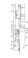
【図1】 要部の断面図である。
【図2】 クッションリングがクッションシールに進入した状態の拡大断面図である。
【図3】 従来構造の要部の断面図である。
【図4】 従来構造のクッションリングがクッションシールに進入した状態の拡大断面図である。
【符号の説明】
21 シリンダチューブ
22 ピストン
24 シリンダ室
26 クッションリング
28 シリンダヘッド
31 ホルダー
32 ストッパー
33 カラー
37 自由流通路
38 シリンダポート[0001]
BACKGROUND OF THE INVENTION
The present invention relates to a cylinder cushion structure for mitigating an impact at a stroke end of a piston.
[0002]
[Prior art]
As a cylinder cushioning device, those shown in FIGS. 3 and 4 are conventionally known, and the structure thereof is as follows.
A
Moreover, a
[0003]
A
In the figure,
[0004]
A
The
[0005]
On the other hand, the
In addition, a
[0006]
Although each member is assembled as described above, a gap is actually formed in the following portion. First, the
Such a mating gap causes a shift in the axis of each member. The above-mentioned mating gaps are integrated and the
[0007]
If the
However, if the
[0008]
Now, when the
[0009]
As shown in FIG. 4, when the
One is a passage that passes between the
In any case, since the flow passage resistance of the two passages is large, the pressure of the
[0010]
Further, as described above, the mating gap on the assembly causes the
[0011]
However, even if the axial center of the
[0012]
On the other hand, when the
Therefore, the pressure fluid supplied from the
[0013]
[Problems to be solved by the invention]
In the conventional cushion structure as described above, when the
In addition, the above-mentioned collision sound resonates with the rattling of the cushion seal, resulting in a considerably high frequency sound, and the sound itself is irritating.
[0014]
In addition, when the axis of the
[0015]
[Means for Solving the Problems]
In this invention, a piston is slidably provided on a cylinder tube, a cylinder head is provided at an end of the cylinder tube, and a piston rod provided on the piston is protruded outward from the cylinder head to form a cylinder tube. The piston is reciprocated by supplying or discharging the pressure fluid from the port, while providing a cushion ring on the piston rod side, and a holder is fixed to the inner end of the cylinder head, It is assumed that a cylinder cushion structure is provided on the inner periphery of the holder so that it can move in the axial direction, and the cushion ring enters the cushion seal when the cushion function is performed.
[0016]
While assuming the above structure, the first invention is, in the inner periphery of the holder, to form a scan topper on the end of the piston side, and the holder to the cylinder head side opposite to the stopper a collar made of separate provided, while to position the cushion seal between the stopper and the color, only setting the spacer between the cushion seal and the stopper, the cushion between the collar and the stopper The seal and the spacer can be moved in the axial direction, and the inner diameter of the spacer is larger than the inner diameter of the cushion seal.
According to the second aspect of the present invention, when the piston moves in the direction opposite to the direction in which the cushion function is exerted, the cushion seal moves in the moving direction of the piston. It is characterized in that a free flow passage for communication is formed in the holder .
[0017]
A third invention is, while a inner end of the upper Symbol color providing a cutout constituting the orifice on the opposite surface of the cushion seal, the free passage will be formed on the inner periphery of the holder, the cushion seal and The spacer is characterized in that the notch and the free flow passage communicate with each other when the spacer moves in a direction opposite to the direction in which the cushion function is exhibited.
[0018]
DETAILED DESCRIPTION OF THE INVENTION
The cushion structure of the cylinder shown in FIGS. 1 and 2 is as follows.
A
In addition, a
[0019]
A
In the figure,
[0020]
A
The
[0021]
The
The
The
[0022]
Each member is assembled as described above. Actually, however, a gap can be formed in the following portion as in the conventional case. That is, the
Such a mating gap causes a shift in the axis of each member. Then, the above-described mating gaps are integrated and the
[0023]
Now, when the
[0024]
As shown in FIG. 2 from the above state, the
Further, when the
[0025]
In this state, the
One is a passage that passes between the
In any case, since the flow passage resistance of the two passages is large, the pressure of the
[0026]
Further, as described above, the mating gap on the assembly causes the
[0027]
For this reason, when the
[0028]
However, even if the
When the
[0029]
In addition, since the working fluid enters between the
For this reason, the resonance point of the
Further, since vibration of the
[0030]
On the other hand, when the
Therefore, the pressure fluid supplied from the
[0031]
【The invention's effect】
According to the first invention, a spacer is provided at a position adjacent to the cushion seal in the rearward direction of the cushion ring, the spacer is movable in the axial direction, and the inner diameter thereof is set to the cushion seal. Therefore, when the cushion ring enters the cushion seal, the vibration of the cushion seal can be stopped. Therefore, the unpleasant sound generated due to the vibration of the cushion seal is not generated, and the cushion seal is not unevenly worn.
In addition to fixing the holder to the cylinder head and incorporating the collar, cushion seal, and spacer in this holder, these parts can be assembled into a cartridge, which improves the production efficiency of the assembly line. Can do.
[0033]
According to the second and third inventions, when the piston moves in the direction opposite to the direction in which the cushion function is exerted, the free flow passage that connects the cylinder port and the cylinder chamber is formed in the holder. The piston can be quickly moved in the direction opposite to the direction in which it is exerted.
[Brief description of the drawings]
FIG. 1 is a cross-sectional view of a main part.
FIG. 2 is an enlarged cross-sectional view of a state in which a cushion ring has entered a cushion seal.
FIG. 3 is a cross-sectional view of a main part of a conventional structure.
FIG. 4 is an enlarged cross-sectional view of a state in which a cushion ring having a conventional structure has entered a cushion seal.
[Explanation of symbols]
21
Claims (3)
Priority Applications (5)
| Application Number | Priority Date | Filing Date | Title |
|---|---|---|---|
| JP2000213786A JP4043173B2 (en) | 2000-07-14 | 2000-07-14 | Cylinder cushion structure |
| GB0116291A GB2364747B (en) | 2000-07-14 | 2001-07-04 | Hydraulic cylinder cushion device |
| US09/902,507 US6523452B2 (en) | 2000-07-14 | 2001-07-09 | Hydraulic cylinder cushion device |
| DE10133581A DE10133581B4 (en) | 2000-07-14 | 2001-07-11 | Hydraulic cylinder with buffer device |
| KR10-2001-0042221A KR100426547B1 (en) | 2000-07-14 | 2001-07-13 | Hydraulic cylinder cushion device |
Applications Claiming Priority (1)
| Application Number | Priority Date | Filing Date | Title |
|---|---|---|---|
| JP2000213786A JP4043173B2 (en) | 2000-07-14 | 2000-07-14 | Cylinder cushion structure |
Publications (3)
| Publication Number | Publication Date |
|---|---|
| JP2002031106A JP2002031106A (en) | 2002-01-31 |
| JP2002031106A5 JP2002031106A5 (en) | 2005-11-04 |
| JP4043173B2 true JP4043173B2 (en) | 2008-02-06 |
Family
ID=18709483
Family Applications (1)
| Application Number | Title | Priority Date | Filing Date |
|---|---|---|---|
| JP2000213786A Expired - Fee Related JP4043173B2 (en) | 2000-07-14 | 2000-07-14 | Cylinder cushion structure |
Country Status (5)
| Country | Link |
|---|---|
| US (1) | US6523452B2 (en) |
| JP (1) | JP4043173B2 (en) |
| KR (1) | KR100426547B1 (en) |
| DE (1) | DE10133581B4 (en) |
| GB (1) | GB2364747B (en) |
Families Citing this family (9)
| Publication number | Priority date | Publication date | Assignee | Title |
|---|---|---|---|---|
| DE102006009094A1 (en) * | 2006-02-28 | 2007-08-30 | Bayerische Motoren Werke Ag | Damper for use between cylinder head and injector in region of injector foot, has sub-functional section e.g. inner ring and outer ring, for fixing injector with respect to cylinder head, where damper is formed as multipart structure |
| JP4871114B2 (en) * | 2006-12-22 | 2012-02-08 | カヤバ工業株式会社 | Cushion structure of fluid pressure cylinder |
| JP4851992B2 (en) | 2007-05-22 | 2012-01-11 | カヤバ工業株式会社 | Cushion ring and fluid pressure cylinder |
| JP5730058B2 (en) * | 2011-02-17 | 2015-06-03 | Kyb−Ys株式会社 | Fluid pressure cylinder |
| JP5767990B2 (en) * | 2012-03-23 | 2015-08-26 | カヤバ工業株式会社 | Fluid pressure cylinder |
| CN102720726A (en) * | 2012-06-15 | 2012-10-10 | 常州液压成套设备厂有限公司 | Hydraulic cylinder with detachable sealing structure |
| JP6113996B2 (en) * | 2012-10-11 | 2017-04-12 | Kyb株式会社 | Fluid pressure cylinder |
| US10935055B2 (en) * | 2017-08-16 | 2021-03-02 | Kyntronics, Inc. | Electrohydraulic actuator |
| JP7323103B2 (en) * | 2020-07-22 | 2023-08-08 | Smc株式会社 | hydraulic cylinder |
Family Cites Families (11)
| Publication number | Priority date | Publication date | Assignee | Title |
|---|---|---|---|---|
| DE7712953U1 (en) * | 1900-01-01 | Praedifa Jaeger Kg Praezisions-Dichtungs- Fabrik Gmbh & Cie, 7120 Bietigheim-Bissingen | ||
| US2710595A (en) * | 1952-06-16 | 1955-06-14 | Hannifin Corp | Fluid operated cylinder with adjustable cushion |
| US3027877A (en) * | 1959-09-11 | 1962-04-03 | Parker Hannifin Corp | Fluid pressure motor |
| US3038448A (en) * | 1960-03-11 | 1962-06-12 | Tomkins Johnson Co | Cylinder construction |
| US3388634A (en) * | 1966-04-08 | 1968-06-18 | Parker Hannifin Corp | Cushioning means for fluid pressure motor |
| US4296675A (en) * | 1979-07-16 | 1981-10-27 | Aeroquip Corporation | Cylinder cushion with contractable ring |
| SE8101054L (en) * | 1981-02-17 | 1982-08-18 | Vaggeryds Mek Verk | DEVICE MUTUAL DEVICE FOR THE PISTON WITH THE PISTON WITH THE ASSEMBLY Piston rod AND MORE COMPONENTS IN A HYDRAULIC CYLINDER |
| JPH0430410Y2 (en) * | 1985-04-19 | 1992-07-22 | ||
| JPH02128806A (en) * | 1988-11-08 | 1990-05-17 | Nec Yamagata Ltd | Manufacture of resin sealed type semiconductor device |
| JP3003715B2 (en) * | 1991-03-29 | 2000-01-31 | 日本バルカー工業株式会社 | Cushion packing for pressure cylinder |
| JP4012623B2 (en) * | 1998-03-30 | 2007-11-21 | カヤバ工業株式会社 | Cylinder device |
-
2000
- 2000-07-14 JP JP2000213786A patent/JP4043173B2/en not_active Expired - Fee Related
-
2001
- 2001-07-04 GB GB0116291A patent/GB2364747B/en not_active Expired - Fee Related
- 2001-07-09 US US09/902,507 patent/US6523452B2/en not_active Expired - Lifetime
- 2001-07-11 DE DE10133581A patent/DE10133581B4/en not_active Expired - Fee Related
- 2001-07-13 KR KR10-2001-0042221A patent/KR100426547B1/en active IP Right Grant
Also Published As
| Publication number | Publication date |
|---|---|
| US20020020288A1 (en) | 2002-02-21 |
| GB2364747B (en) | 2004-08-18 |
| KR100426547B1 (en) | 2004-04-13 |
| DE10133581B4 (en) | 2004-07-15 |
| JP2002031106A (en) | 2002-01-31 |
| US6523452B2 (en) | 2003-02-25 |
| GB0116291D0 (en) | 2001-08-29 |
| DE10133581A1 (en) | 2002-01-31 |
| KR20020006645A (en) | 2002-01-24 |
| GB2364747A (en) | 2002-02-06 |
Similar Documents
| Publication | Publication Date | Title |
|---|---|---|
| JP4043173B2 (en) | Cylinder cushion structure | |
| ITTO940375A1 (en) | MOTOR VEHICLE BRAKE. | |
| US6431290B1 (en) | Electric hand tool device with idle strike cutoff | |
| JP6628804B2 (en) | Damper | |
| JP2005510372A (en) | Hand-held machine tool with pneumatic striking mechanism | |
| JP2007146947A (en) | Hydraulic shock absorber | |
| KR101304629B1 (en) | External part of a switchable bucket tappet | |
| JP3946424B2 (en) | Cylinder cushion structure | |
| JP4009411B2 (en) | Cylinder cushion structure | |
| JP2000120757A (en) | Hydraulic buffer | |
| WO2019225738A1 (en) | Valve | |
| JPH09329177A (en) | Shaft seal device of single tube-type damper | |
| JP2010500945A (en) | Servo brake | |
| JP3863864B2 (en) | Fluid pressure cylinder | |
| JP4657519B2 (en) | Shock absorber | |
| WO2022097378A1 (en) | Shock absorber | |
| JP4040812B2 (en) | Relief valve | |
| JPS5932653B2 (en) | Piston strike noise prevention device for internal combustion engines | |
| JP2019196777A (en) | Spool valve | |
| JP3978637B2 (en) | Front fork | |
| JP4048079B2 (en) | Hydraulic shock absorber | |
| JP2001132790A (en) | Hydraulic buffer | |
| JPS5836882Y2 (en) | Cushion mechanism of fluid pressure cylinder | |
| JPH08270785A (en) | Transmission operating device | |
| JPH0381010B2 (en) |
Legal Events
| Date | Code | Title | Description |
|---|---|---|---|
| A521 | Request for written amendment filed |
Free format text: JAPANESE INTERMEDIATE CODE: A523 Effective date: 20050805 |
|
| A621 | Written request for application examination |
Free format text: JAPANESE INTERMEDIATE CODE: A621 Effective date: 20051031 |
|
| A977 | Report on retrieval |
Free format text: JAPANESE INTERMEDIATE CODE: A971007 Effective date: 20061030 |
|
| A131 | Notification of reasons for refusal |
Free format text: JAPANESE INTERMEDIATE CODE: A131 Effective date: 20061107 |
|
| A521 | Request for written amendment filed |
Free format text: JAPANESE INTERMEDIATE CODE: A523 Effective date: 20061205 |
|
| A02 | Decision of refusal |
Free format text: JAPANESE INTERMEDIATE CODE: A02 Effective date: 20070313 |
|
| A521 | Request for written amendment filed |
Free format text: JAPANESE INTERMEDIATE CODE: A523 Effective date: 20070411 |
|
| A911 | Transfer to examiner for re-examination before appeal (zenchi) |
Free format text: JAPANESE INTERMEDIATE CODE: A911 Effective date: 20070517 |
|
| TRDD | Decision of grant or rejection written | ||
| A01 | Written decision to grant a patent or to grant a registration (utility model) |
Free format text: JAPANESE INTERMEDIATE CODE: A01 Effective date: 20071017 |
|
| A61 | First payment of annual fees (during grant procedure) |
Free format text: JAPANESE INTERMEDIATE CODE: A61 Effective date: 20071113 |
|
| R151 | Written notification of patent or utility model registration |
Ref document number: 4043173 Country of ref document: JP Free format text: JAPANESE INTERMEDIATE CODE: R151 |
|
| FPAY | Renewal fee payment (event date is renewal date of database) |
Free format text: PAYMENT UNTIL: 20101122 Year of fee payment: 3 |
|
| FPAY | Renewal fee payment (event date is renewal date of database) |
Free format text: PAYMENT UNTIL: 20111122 Year of fee payment: 4 |
|
| FPAY | Renewal fee payment (event date is renewal date of database) |
Free format text: PAYMENT UNTIL: 20111122 Year of fee payment: 4 |
|
| FPAY | Renewal fee payment (event date is renewal date of database) |
Free format text: PAYMENT UNTIL: 20121122 Year of fee payment: 5 |
|
| FPAY | Renewal fee payment (event date is renewal date of database) |
Free format text: PAYMENT UNTIL: 20131122 Year of fee payment: 6 |
|
| S533 | Written request for registration of change of name |
Free format text: JAPANESE INTERMEDIATE CODE: R313533 |
|
| R350 | Written notification of registration of transfer |
Free format text: JAPANESE INTERMEDIATE CODE: R350 |
|
| LAPS | Cancellation because of no payment of annual fees |