JP4042002B2 - Packaging machinery - Google Patents
Packaging machinery Download PDFInfo
- Publication number
- JP4042002B2 JP4042002B2 JP25491197A JP25491197A JP4042002B2 JP 4042002 B2 JP4042002 B2 JP 4042002B2 JP 25491197 A JP25491197 A JP 25491197A JP 25491197 A JP25491197 A JP 25491197A JP 4042002 B2 JP4042002 B2 JP 4042002B2
- Authority
- JP
- Japan
- Prior art keywords
- filling
- clean
- clean booth
- nozzle
- booth
- Prior art date
- Legal status (The legal status is an assumption and is not a legal conclusion. Google has not performed a legal analysis and makes no representation as to the accuracy of the status listed.)
- Expired - Fee Related
Links
Images


Classifications
-
- B—PERFORMING OPERATIONS; TRANSPORTING
- B65—CONVEYING; PACKING; STORING; HANDLING THIN OR FILAMENTARY MATERIAL
- B65B—MACHINES, APPARATUS OR DEVICES FOR, OR METHODS OF, PACKAGING ARTICLES OR MATERIALS; UNPACKING
- B65B55/00—Preserving, protecting or purifying packages or package contents in association with packaging
- B65B55/02—Sterilising, e.g. of complete packages
- B65B55/025—Packaging in aseptic tunnels
Landscapes
- Engineering & Computer Science (AREA)
- Mechanical Engineering (AREA)
- Vacuum Packaging (AREA)
- Basic Packing Technique (AREA)
Description
【0001】
【発明の属する技術分野】
この発明は、包装機械、詳しくは、クリーンな環境下で、容器に内容物を充填する等の包装作業をなしうる包装機械に関する。
【0002】
【従来の技術】
この種の包装機械としては、ベッド上面を被覆するように下方開放箱型クリーンブースが配置され、クリーンブース頂壁にクリーンエア吹出口が下向きに設けられており、ベッド上面とクリーンブース下端の間にはエア排出用間隙が形成されており、クリーンブース内に容器搬送コンベヤが設置され、容器搬送経路にそって所要の包装作業をなしうる装置群が配置されており、装置群が、充填装置を有しており、充填装置が、充填ノズルと、充填ノズルに充填液を供給する充填装置本体と、充填ノズルと充填装置本体を接続している接続パイプを備えており、充填ノズル、充填装置本体および接続パイプが、いずれもクリーンブース内に配置されているものが知られている。
【0003】
【発明が解決しようとする課題】
上記包装機械では、充填装置の全体がクリーンブース内にあるため、充填装置周辺部のクリーンエアの流れが充填装置によって乱され、これにより、クリーンブース内に外気が進入し、クリーンブース内が汚染される恐れがあった。外気の進入を防止するためには、クリーンブースに供給するクリーンエアの風量を増加させらればよいが、これは経済的ではない。
【0004】
この発明の目的は、クリーンブース内を必要最小限のエアー量で理想的な陽圧下に保ち、クリーンな環境下で容器の製造をすることができる包装機械を提供することにある。
【0005】
【課題を解決するための手段】
この発明による包装機械は、ベッド上面に下方開放箱型クリーンブースが配置され、クリーンブース頂壁にクリーンエア吹出口が下向きに設けられており、ベッド上面とクリーンブース下端の間にはエア排出用間隙が形成されており、クリーンブース内に、前向きにのびた搬送経路を有する容器搬送コンベヤが設置され、容器搬送経路にそって所要の包装作業をなしうる装置群が配置されており、装置群が、充填装置を有している包装機械において、充填装置が、クリーンブース内における容器搬送経路上方に配置されている充填ノズルと、クリーンブース外に配置されかつ充填ノズルに充填液を供給する充填装置本体と、クリーンブースの内外にわたって配置されかつ充填ノズルと充填装置本体を接続している接続パイプを備えていることを特徴とするものである。
【0006】
この発明による包装機械では、充填装置が、クリーンブース内における容器搬送経路上方に配置されている充填ノズルと、クリーンブース外に配置されかつ充填ノズルに充填液を供給する充填装置本体と、クリーンブースの内外にわたって配置されかつ充填ノズルと充填装置本体を接続している接続パイプを備えているから、クリーンブース内には充填装置の充填ノズルがあるだけである。クリーンブースの天井から下向きに吹き出されたクリーンエアーは、充填装置本体等によってその流れが乱されることなく、充填ノズルの周囲を層流となって流れる。したがって、クリーンブース内に外気が進入する心配が無く、クリーンな環境下で容器に充填作業をすることができる。
【0007】
クリーンブース内において、充填ノズルおよびその周辺部を仕切壁によって取り囲み、充填チャンバを形成するようにしてもよい。
【0008】
クリーンエア吹出口から吹出されるクリーンエアによってクリーンブースまたは充填チャンバ内が陽圧に保持しうるようになされていることが好ましい。
【0009】
充填装置本体が、充填液タンクと、タンクから充填液を一定量ずつ流入しかつ流入した充填液を接続パイプを通じて充填ノズルに流出する定量シリンダを備えているタイプのものであってもよい。
【0010】
【発明の実施の形態】
この発明の実施の形態を図面を参照してつぎに説明する。
【0011】
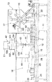
以下の説明において、前後とは、図1の左側を前、これと反対側を後といい、左右とは、前に向かって、その左右の側を左右というものとする。
【0012】
図1を参照すると、包装機械は、前後方向に長い方形板状脚11付きベッド12と、ベッド12の上面を被覆するように配置されている下方開放箱型クリーンブース13とを備えている。
【0013】
クリーンブース13内の後部高さの中程には、放射状マンドレル14を有し、マンドレル14がこれと同数の処理ステーションに順次停止させられるように配置されている間欠駆動ロータ15が配置されている。ロータ15の下方から前に向かって間欠駆動容器搬送コンベヤ16が配置されている。マンドレル14の移動経路にそう所要処理ステーションに第1装置群17が配置されている。コンベヤ16の搬送経路にそって第2装置群18が配置されている。
【0014】
図示しないが、ロータ15は、4つの左右並列状マンドレル輪を有している。容器搬送コンベヤ16は、2つの左右並列状容器搬送経路を有している。第1装置群17は、マンドレ輪の数に対応して、同一構成要素よりなる4つずつの構成ユニットを有している。第2装置群18は、容器搬送経路の数に対応して、同一構成要素よりなる2つずつの構成ユニットを有している。
【0015】
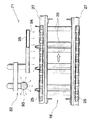
コンベヤ16の左右の搬送経路は、同一構造のものである。コンベヤ16の各搬送経路は、図3に示すように、左右一対ずつの垂直前駆動軸21および後従動軸22と、左右それぞれの側において前駆動軸21および後従動軸22に上下一対ずつ取付けられている左右の駆動スプロケット23および従動スプロケット24と、左右それぞれの側において上下同じ側の駆動スプロケット23および従動スプロケット24にそれぞれ巻き掛けられている左右のエンドレスチェーン25と、左右それぞれの側において上下のチェーン25に渡し止められている複数の横断面L字垂直片よりなるホルダプレート26と、チェーン25の所要部分がそわされている樹脂製ガイド27(図4参照)と、左右のチェーン25間下方に配置されている水平ガイドレール28とを備えている。
【0016】
平面より見て、左チェーン25が反時計方向に駆動され、右チェーン25が時計方向に駆動される。左右のチェーン25の相対して前向きに移動する部分が送り側経路を形成する。左右の送り側経路を移動するチェーン25の2つずつのホルダプレート26が容器Cの四隅にあてがわれるとともに、同容器Cの底がガイドレール28で受けられた状態で容器Cが前向きに搬送されるようになっている。
【0017】
第1装置群17の各ユニットによって、マンドレル14に角筒状ブランクがはめ被せられ、はめ被せられたブランクの容器底部となる端部が平坦に折畳まれて有底角筒状容器Cとされる。第1装置群17によって一度に形成される容器の数は、4つである。4つの容器はコンベヤ16の左右の容器搬送経路に2つずつ渡される。各容器搬送経路では1ピッチの駆動で容器が2つずつ搬送されていく。第2装置群18の各ユニットによって、コンベヤ16で搬送される容器Cに内容物が充填され、内容物を充填した容器Cの頂部が切妻屋根型に折畳まれて閉じられ、密封容器Cが完成する。
【0018】
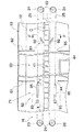
第2装置群18は、左右の充填装置31を有している。図2に示すように、左右の充填装置31は、左右の向きは異にするが、同一構造のものである。すなわち、各充填装置31は、容器搬送ピッチに対応して、前後2つずつの充填ノズル41、充填装置本体42および接続パイプ43を備えている(図1参照)。
【0019】
ベッド12の上面には、左右の容器搬送経路の間に通されたスタンド44が設けられている。スタンド44の上端には左右反対方向にのびた左右のアーム45が設けられている。両アーム45の先端は、それぞれ左右の容器搬送経路の上方に達している。
【0020】
充填ノズル41は、垂直筒状のもので、左右対応するがわのアームの先端に2つずつ並んで取付けられており、この状態で、クリーンブース13内において容器搬送経路の真上に位置させられている。
【0021】
充填装置本体42は、クリーンブース13外に配置されかつ充填液タンク51および定量シリンダ52を備えている。定量シリンダ52は、図示しないピストンを内蔵し、ピストンの作動により、タンク51から充填液を一定量ずつ流入しかつ流入した充填液を接続パイプ43を通じて充填ノズル41に流出する。
【0022】
接続パイプ43は、クリーンブース13の側壁を貫通して充填ノズル41および定量シリンダ52に渡されている。
【0023】
左右の充填ノズルを挟んでその上流側および下流側に、前後の垂直板状仕切壁61,62が設けられている。これにより、クリーンブース13内における両仕切壁61,62間に充填チャンバ64が形成されている。両仕切壁61,62の下縁部には、コンベヤ16および容器Cとの干渉を避けるための切欠64,65が形成されている。
【0024】
図3に、コンベヤ殺菌装置71が示されている。コンベヤ殺菌装置71は、左右のチェーンの送り側経路における後仕切壁62より後方に配置されている第1殺菌液ノズル81と、同戻り側経路における前仕切壁61より前方に配置されている第2殺菌液ノズル82とを備えている。第1殺菌液ノズル81は、図4に詳しく示すように、吐出口91を同移動経路に上方より臨ませている逆U字状滴下パイプ92よりなる。第2殺菌液ノズル82は、図5に詳しく示すように、同移動経路上方に下向きに配置されているスプレイボール93と、これの後方に配置されかつ多数の下向き吐出口94が1列に並んであけられている水平滴下パイプ95とよりなる。
【0025】
殺菌液としては、電解酸性水が用いられている。電解酸性水は、強い殺菌力を発揮する。電解酸性水によってコンベヤ16が充填チャンバ63に導入される直前に殺菌されるため、コンベヤ16が外気と接触し、これによりコンベヤ16に付着した微生物等によって汚染される心配がない。また、電解酸性水は、人体や機械の金属部分に悪い影響を与える心配がない。さらに、電解酸性水が潤滑水としての作用をなすため、チェーン25およびホルダプレート26と、ガイド27との接触部分の滑り抵抗が良くなり、コンベヤ駆動抵抗が減少され部品寿命が延長される。
【0026】
再び図2を参照すると、充填チャンバ63の天井にあたる部分にはエアフィルタ101 が装備されている。エアフィルタ101 は、下方開放箱型ケーシング102 を有している。ケーシング102 の頂壁にはエアダクト103 が接続されている。ケーシング103 の下端開口は吹出口104 となっている。吹出口104 の下方には多孔板製整流板105 が設けられている。
【0027】
クリーンブース13の左右両側壁下端とベッド12上面両縁間には隙間がそれぞれ形成されており、これらの隙間を通じてエアーが流出するようになっている。
【0028】
フィルタ101 から吹き出されたクリーンエアーは、整流板105 を通過させられることにより、充填チャンバ63内の全体で流速の均一な層流となって、充填チャンバ63内を下向きに流れる。充填チャンバ63内には充填装置31の充填ノズル41および接続パイプ43の一部があるだけであるから、クリンエアーの流れが乱されることなく、充填ノズル41の周囲をスムースに流れる。
【0029】
エアフィルタ101 から吹出されるクリーンエアーの風量と、ベッド12とクリンブース13の間から排出される風量のバランスを適切に設定することにより、充填チャンバ63内は陽圧に保たれる。クリーンエアーの流れが乱され無いことにより、充填チャンバ63内の圧力にも変動が生じること無く、充填チャンバ63内から外に一定量ずつクリンエアーが排出されていくため、外気が充填チャンバ63内に逆流する心配が無い。
【0030】
【発明の効果】
この発明によれば、クリーンブース内を必要最小限のエアー量で理想的な陽圧下に保つことができ、クリーンな環境下で容器の製造をすることができる。
【図面の簡単な説明】
【図1】この発明による包装機械の側面図である。
【図2】同包装機械の充填装置周辺部の横断面図である。
【図3】同包装機械のコンベヤおよびこれの殺菌装置の平面図である。
【図4】図3のIVーIV線にそう断面図である。
【図5】図3のVーV線にそう断面図である。
【符号の説明】
12 ベッド
13 クリーンブース
16 コンベヤ
18 装置群
31 充填装置
41 充填ノズル
42 装置本体
43 接続パイプ
61 前仕切壁
62 後仕切壁
63 接続パイプ
104 吹出口[0001]
BACKGROUND OF THE INVENTION
The present invention relates to a packaging machine, and more particularly to a packaging machine capable of performing a packaging operation such as filling a container with contents in a clean environment.
[0002]
[Prior art]
As this type of packaging machine, a lower open box type clean booth is arranged so as to cover the upper surface of the bed, and a clean air outlet is provided downward on the clean booth top wall, between the upper surface of the bed and the lower end of the clean booth. Has a gap for air discharge, a container transport conveyor is installed in the clean booth, and a group of devices that can perform the required packaging work along the container transport path is arranged. The filling device includes a filling nozzle, a filling device main body that supplies a filling liquid to the filling nozzle, and a connection pipe that connects the filling nozzle and the filling device main body. It is known that both the main body and the connecting pipe are arranged in a clean booth.
[0003]
[Problems to be solved by the invention]
In the above packaging machine, since the entire filling device is in the clean booth, the flow of clean air around the filling device is disturbed by the filling device, which causes outside air to enter the clean booth and contaminate the clean booth. There was a fear. In order to prevent outside air from entering, it is only necessary to increase the amount of clean air supplied to the clean booth, but this is not economical.
[0004]
An object of the present invention is to provide a packaging machine capable of manufacturing a container in a clean environment while keeping the inside of a clean booth under an ideal positive pressure with a minimum amount of air.
[0005]
[Means for Solving the Problems]
In the packaging machine according to the present invention, a lower open box type clean booth is arranged on the upper surface of the bed, and a clean air outlet is provided downward on the top wall of the clean booth. A gap is formed, a container transport conveyor having a transport path extending forward is installed in the clean booth, and a group of devices that can perform a required packaging operation along the container transport path is arranged. In the packaging machine having the filling device, the filling device is disposed above the container conveyance path in the clean booth, and the filling device is disposed outside the clean booth and supplies the filling liquid to the filling nozzle. It has a connecting pipe that is arranged over the main body and the inside and outside of the clean booth and connects the filling nozzle and the filling device main body. It is an feature.
[0006]
In the packaging machine according to the present invention, the filling device includes a filling nozzle disposed above the container conveyance path in the clean booth, a filling device body disposed outside the clean booth and supplying the filling liquid to the filling nozzle, and the clean booth. In the clean booth, there is only a filling nozzle of the filling device because the connecting pipe connecting the filling nozzle and the filling device main body is provided. The clean air blown downward from the ceiling of the clean booth flows in a laminar flow around the filling nozzle without being disturbed by the filling device main body or the like. Therefore, there is no concern that outside air will enter the clean booth, and the container can be filled in a clean environment.
[0007]
In the clean booth, the filling nozzle and its peripheral part may be surrounded by a partition wall to form a filling chamber.
[0008]
It is preferable that the clean booth or the filling chamber can be maintained at a positive pressure by the clean air blown from the clean air outlet.
[0009]
The filling device main body may be of a type provided with a filling liquid tank and a metering cylinder for inflowing a certain amount of filling liquid from the tank and flowing the filled liquid into the filling nozzle through a connecting pipe.
[0010]
DETAILED DESCRIPTION OF THE INVENTION
Embodiments of the present invention will be described below with reference to the drawings.
[0011]
In the following description, the front and rear refer to the left side of FIG. 1 as the front and the opposite side as the rear, and the left and right refer to the front and the left and right sides as the left and right.
[0012]
Referring to FIG. 1, the packaging machine includes a
[0013]
In the middle of the rear height in the
[0014]
Although not shown, the
[0015]
The left and right transport paths of the
[0016]
When viewed from the plane, the
[0017]
A square tube blank is put on the
[0018]
The
[0019]
On the upper surface of the
[0020]
The filling
[0021]
The filling device
[0022]
The
[0023]
Front and rear vertical plate-
[0024]
In FIG. 3, a
[0025]
As the sterilizing solution, electrolytic acid water is used. Electrolytic acid water exhibits a strong bactericidal power. Since the
[0026]
Referring to FIG. 2 again, an
[0027]
Gaps are formed between the lower ends of the left and right side walls of the
[0028]
The clean air blown out from the
[0029]
By appropriately setting the balance between the amount of clean air blown from the
[0030]
【The invention's effect】
According to this invention, the inside of the clean booth can be kept under an ideal positive pressure with a minimum amount of air, and the container can be manufactured in a clean environment.
[Brief description of the drawings]
FIG. 1 is a side view of a packaging machine according to the present invention.
FIG. 2 is a cross-sectional view of the periphery of the filling device of the packaging machine.
FIG. 3 is a plan view of the conveyor of the packaging machine and a sterilizing apparatus for the conveyor.
4 is a cross-sectional view taken along line IV-IV in FIG.
FIG. 5 is a cross-sectional view taken along line VV in FIG.
[Explanation of symbols]
12 beds
13 Clean booth
16 conveyor
18 devices
31 Filling equipment
41 Filling nozzle
42 Main unit
43 Connection pipe
61 Front partition
62 Rear partition wall
63 Connection pipe
104 Air outlet
Claims (5)
充填装置が、クリーンブース内における容器搬送経路上方に配置されている充填ノズルと、クリーンブース外に配置されかつ充填ノズルに充填液を供給する充填装置本体と、クリーンブースの内外にわたって配置されかつ充填ノズルと充填装置本体を接続している接続パイプを備えており、
クリーンエア吹出口が、充填ノズルの上方に位置させられ、クリーンエア吹出口に多孔板製整流板が被覆され、整流板を通過させられたエアが充填ノズルの周囲を層流となって下向きに流れるようになされている、
ことを特徴とする包装機械。A lower open box type clean booth is arranged on the upper surface of the bed, a clean air outlet is provided downward on the top wall of the clean booth, and an air discharge gap is formed between the upper surface of the bed and the lower end of the clean booth. In the clean booth, a container transport conveyor having a forwardly extending transport path is installed, and a group of devices capable of performing a required packaging operation along the container transport path is arranged. In the packaging machine
The filling device is disposed and filled over the inside and outside of the clean booth, the filling nozzle disposed above the container conveyance path in the clean booth, the filling device main body disposed outside the clean booth and supplying the filling liquid to the filling nozzle It has a connection pipe connecting the nozzle and the filling device body ,
The clean air outlet is located above the filling nozzle, the clean air outlet is covered with a perforated plate rectifier, and the air that has passed through the rectifier becomes a laminar flow around the filling nozzle downwards Is made to flow,
A packaging machine characterized by that.
容器搬送経路と交差させられた前および/または後仕切壁によってクリーンブース内に充填チャンバが形成され、
充填装置が、充填チャンバ内における容器搬送経路上方に配置されている充填ノズルと、充填チャンバ外に配置されかつ充填ノズルに充填液を供給する充填装置本体と、充填チャンバの内外にわたって配置されかつ充填ノズルと充填装置本体を接続している接続パイプを備えており、
クリーンエア吹出口が、充填ノズルの上方に位置させられ、クリーンエア吹出口に多孔板製整流板が被覆され、整流板を通過させられたエアが充填ノズルの周囲を層流となって下向きに流れるようになされている、
ことを特徴とする包装機械。A lower open box type clean booth is arranged on the upper surface of the bed, a clean air outlet is provided downward on the top wall of the clean booth, and an air discharge gap is formed between the upper surface of the bed and the lower end of the clean booth. In the clean booth, a container transport conveyor having a forwardly extending transport path is installed, and a group of devices capable of performing a required packaging operation along the container transport path is arranged, and the apparatus group has a filling device. In the packaging machine
A filling chamber is formed in the clean booth by the front and / or rear partition walls intersecting the container transport path,
A filling device is disposed and filled over the inside and outside of the filling chamber, a filling nozzle disposed above the container conveyance path in the filling chamber, a filling device body disposed outside the filling chamber and supplying a filling liquid to the filling nozzle. It has a connection pipe connecting the nozzle and the filling device body ,
The clean air outlet is positioned above the filling nozzle, and the clean air outlet is covered with a rectifying plate made of porous plate, and the air that has passed through the rectifying plate flows downward around the filling nozzle as a laminar flow Made to flow,
A packaging machine characterized by that.
Priority Applications (4)
| Application Number | Priority Date | Filing Date | Title |
|---|---|---|---|
| JP25491197A JP4042002B2 (en) | 1997-09-19 | 1997-09-19 | Packaging machinery |
| DK98202856T DK0903297T3 (en) | 1997-09-19 | 1998-08-27 | Clean air booth for a packaging machine |
| EP19980202856 EP0903297B1 (en) | 1997-09-19 | 1998-08-27 | Clean air booth for a packaging machine |
| DE69840925T DE69840925D1 (en) | 1997-09-19 | 1998-08-27 | Clean air hood for a packaging machine |
Applications Claiming Priority (1)
| Application Number | Priority Date | Filing Date | Title |
|---|---|---|---|
| JP25491197A JP4042002B2 (en) | 1997-09-19 | 1997-09-19 | Packaging machinery |
Publications (2)
| Publication Number | Publication Date |
|---|---|
| JPH1191720A JPH1191720A (en) | 1999-04-06 |
| JP4042002B2 true JP4042002B2 (en) | 2008-02-06 |
Family
ID=17271570
Family Applications (1)
| Application Number | Title | Priority Date | Filing Date |
|---|---|---|---|
| JP25491197A Expired - Fee Related JP4042002B2 (en) | 1997-09-19 | 1997-09-19 | Packaging machinery |
Country Status (4)
| Country | Link |
|---|---|
| EP (1) | EP0903297B1 (en) |
| JP (1) | JP4042002B2 (en) |
| DE (1) | DE69840925D1 (en) |
| DK (1) | DK0903297T3 (en) |
Families Citing this family (14)
| Publication number | Priority date | Publication date | Assignee | Title |
|---|---|---|---|---|
| DE19947786A1 (en) * | 1999-10-05 | 2001-04-19 | Bosch Gmbh Robert | Packaging machine, in particular for filling and closing containers containing liquid pharmaceuticals |
| JP2001240236A (en) * | 2000-03-01 | 2001-09-04 | Shikoku Kakoki Co Ltd | Conveyor |
| JP4484192B2 (en) * | 2002-09-20 | 2010-06-16 | 日本テトラパック株式会社 | Food packaging filling machine |
| FR2882341B1 (en) * | 2005-02-23 | 2009-11-20 | Serac Group | INSTALLATION OF ASEPTIC PACKAGING WITH ASEPTIC BUFFER ZONES |
| JP4916166B2 (en) * | 2005-12-12 | 2012-04-11 | 出光興産株式会社 | Filling nozzle, resin pellet filling system, and resin pellet filling method |
| FR2923474B1 (en) | 2007-11-13 | 2013-08-16 | Sidel Participations | FILLING UNIT FOR CONTAINERS COMPRISING AN ISOLATOR, IN PARTICULAR FOR A PRODUCTION PLANT |
| RU2528691C2 (en) | 2009-07-03 | 2014-09-20 | Тетра Лаваль Холдингз Энд Файнэнс С.А. | Method and device for maintaining barrier of gas flow between two connected capacities |
| DE102015122876A1 (en) * | 2015-12-28 | 2017-06-29 | Sig Technology Ag | Device and method for sterilizing the filling of preferably liquid food in packing containers |
| DE102016108281A1 (en) * | 2016-05-04 | 2017-11-09 | Grunwald GmbH | Filling device with housing and flow device |
| WO2021063992A1 (en) * | 2019-10-04 | 2021-04-08 | Tetra Laval Holdings & Finance S.A. | A filling machine with hygienic chamber |
| WO2022176907A1 (en) * | 2021-02-22 | 2022-08-25 | 四国化工機株式会社 | Filling and packaging machine |
| JP7659180B2 (en) * | 2021-05-31 | 2025-04-09 | 澁谷工業株式会社 | Processing System |
| EP4335761A1 (en) * | 2022-09-07 | 2024-03-13 | Elopak Asa | Filling machine comprising airflow system |
| EP4335763A1 (en) * | 2022-09-07 | 2024-03-13 | Elopak Asa | Filling machine comprising airflow system |
Family Cites Families (2)
| Publication number | Priority date | Publication date | Assignee | Title |
|---|---|---|---|---|
| US3828833A (en) * | 1969-05-08 | 1974-08-13 | Heinz Co H J | Aseptic container filling apparatus |
| DE3607322A1 (en) * | 1986-03-06 | 1987-09-10 | Bosch Gmbh Robert | PASTER-FREE PACKING DEVICE |
-
1997
- 1997-09-19 JP JP25491197A patent/JP4042002B2/en not_active Expired - Fee Related
-
1998
- 1998-08-27 DE DE69840925T patent/DE69840925D1/en not_active Expired - Lifetime
- 1998-08-27 EP EP19980202856 patent/EP0903297B1/en not_active Expired - Lifetime
- 1998-08-27 DK DK98202856T patent/DK0903297T3/en active
Also Published As
| Publication number | Publication date |
|---|---|
| JPH1191720A (en) | 1999-04-06 |
| EP0903297A1 (en) | 1999-03-24 |
| DK0903297T3 (en) | 2009-09-14 |
| EP0903297B1 (en) | 2009-06-24 |
| DE69840925D1 (en) | 2009-08-06 |
Similar Documents
| Publication | Publication Date | Title |
|---|---|---|
| JP4042002B2 (en) | Packaging machinery | |
| US8728249B2 (en) | Packing machine | |
| US6351924B1 (en) | Method and device for sterilizing and filling packing containers | |
| US4693052A (en) | Apparatus for aseptic packaging | |
| US7162848B2 (en) | Filling device with housing having a directed gas supply | |
| EP0261745A2 (en) | Apparatus for sterilizing containers | |
| US4590734A (en) | Packaging machine | |
| JPS6133271A (en) | Base material spray coating system | |
| JP7737731B2 (en) | filling packaging machine | |
| EP0533353A2 (en) | Flexible, compact vial washer | |
| US6041834A (en) | Liquid filling device | |
| JP4651775B2 (en) | Unit for sterilizing strip packaging materials | |
| EP0162968B1 (en) | Packaging machine | |
| JP3899812B2 (en) | Manufacturing method and apparatus for aseptic filling cans | |
| US6561203B2 (en) | Container cleaning, draining and drying apparatus | |
| KR20110000218U (en) | Cleaning device | |
| JPH0114097B2 (en) | ||
| CN218231826U (en) | Quality inspection and packaging device for composite quaternary ammonium salt cleaning disinfectant | |
| CN214605372U (en) | Automatic feeding device with protection structure for plastic uptake machine | |
| CN211871353U (en) | Health care dairy products conveyor | |
| JPH03124527A (en) | Cleaning method and device for filling and packaging machines | |
| JPS6241932B2 (en) | ||
| JPS627049B2 (en) | ||
| JPH07187150A (en) | Packing machine | |
| SE505487C2 (en) | industrial Washing Machine |
Legal Events
| Date | Code | Title | Description |
|---|---|---|---|
| A621 | Written request for application examination |
Free format text: JAPANESE INTERMEDIATE CODE: A621 Effective date: 20040901 |
|
| A977 | Report on retrieval |
Free format text: JAPANESE INTERMEDIATE CODE: A971007 Effective date: 20061226 |
|
| A131 | Notification of reasons for refusal |
Free format text: JAPANESE INTERMEDIATE CODE: A131 Effective date: 20070116 |
|
| A521 | Written amendment |
Free format text: JAPANESE INTERMEDIATE CODE: A523 Effective date: 20070313 |
|
| TRDD | Decision of grant or rejection written | ||
| A01 | Written decision to grant a patent or to grant a registration (utility model) |
Free format text: JAPANESE INTERMEDIATE CODE: A01 Effective date: 20071002 |
|
| A61 | First payment of annual fees (during grant procedure) |
Free format text: JAPANESE INTERMEDIATE CODE: A61 Effective date: 20071031 |
|
| R150 | Certificate of patent or registration of utility model |
Free format text: JAPANESE INTERMEDIATE CODE: R150 |
|
| FPAY | Renewal fee payment (event date is renewal date of database) |
Free format text: PAYMENT UNTIL: 20101122 Year of fee payment: 3 |
|
| FPAY | Renewal fee payment (event date is renewal date of database) |
Free format text: PAYMENT UNTIL: 20131122 Year of fee payment: 6 |
|
| R250 | Receipt of annual fees |
Free format text: JAPANESE INTERMEDIATE CODE: R250 |
|
| LAPS | Cancellation because of no payment of annual fees |