JP4040748B2 - MRI equipment - Google Patents
MRI equipment Download PDFInfo
- Publication number
- JP4040748B2 JP4040748B2 JP14488398A JP14488398A JP4040748B2 JP 4040748 B2 JP4040748 B2 JP 4040748B2 JP 14488398 A JP14488398 A JP 14488398A JP 14488398 A JP14488398 A JP 14488398A JP 4040748 B2 JP4040748 B2 JP 4040748B2
- Authority
- JP
- Japan
- Prior art keywords
- scan
- phase encoding
- slice
- subject
- mri apparatus
- Prior art date
- Legal status (The legal status is an assumption and is not a legal conclusion. Google has not performed a legal analysis and makes no representation as to the accuracy of the status listed.)
- Expired - Lifetime
Links
Images
Landscapes
- Magnetic Resonance Imaging Apparatus (AREA)
Description
【0001】
【発明の属する技術分野】
本発明は、被検体の磁気共鳴現象に基づいて被検体内部を画像化する磁気共鳴イメージングに関する。とくに、被検体の原子核スピンの横緩和(T2緩和)時間が短めの組織や血流などの撮像に好適なMRI(磁気共鳴イメージング)装置に関する。
【0002】
【従来の技術】
磁気共鳴イメージングは、静磁場中に置かれた被検体の原子核スピンをそのラーモア周波数の高周波信号で磁気的に励起し、この励起に伴って発生するMR信号を使って画像を再構成したり、MRスペクトルを得る手法である。
【0003】
この磁気共鳴イメージングによって肺野の血管や肝臓の血管(門脈)などを撮像する場合、種々の要求がある。その1つは、血管像の信号値を上げてS/Nを良くすること、また別の要求は、体動に因るアーチファクトを低減することである。
【0004】
前者の信号値を上げる手法として、画素毎にn(>1)個のMRデータをアベレージング処理(加算平均化処理)する方法がある。このアベレージング処理を実施するために、ショット数や撮像回数を増やして各画素に対するデータ数を増やし、各画素での積算回数を上げるようにしている。このアベレージング処理を行う場合、従来では、そのMR信号収集時の位相エンコード方向は常に一定方向に設定されている。
【0005】
また、後者の体動アーチファクトの発生を抑制するには、患者に息止めを行ってもらう方法がある。これにより、肺の運動に因る体動アーチファクトを低減させることはできる。しかし、この息止めが複数回にわたり、各息止め期間にデータ収集を行って得たMRデータから画像を生成するときには、患者の体の位置自体が動くことに因る体動アーチファクトなどの影響に因り、画像にボケ(blur- ring)が生じることがある。このため、息止めは通常1回だけ行うようにし、この1回の息止めの間に、アベレージング法のための積算回数を上げるように努めている。
【0006】
【発明が解決しようとする課題】
しかしながら、とくにFSE法やEPI法などのパルスシーケンスを使用した撮像では、上述した従来の1回の息止めとアベレージング法とを採用した場合でも、T2 時間が短め(T2 =100〜200ms)の成分(血流、とくに肺野の血管や肝臓の血管(門脈)あるいは脈管など)の走行状態を良好に表示することができず、描出能の点で不満があった。
【0007】
これは、かかるT2 時間が短めの成分(以下、簡単に血流として説明する。)から発生するMR信号の半値幅が位相エンコード方向に広がり(伸び)、画像全体が位相エンコード方向にぼけることに起因する。画像が位相エンコード方向にぼけると、その位相エンコード方向に交差する(直交するなど)血流像の画素値は周辺組織のそれと平均化されてしまい、分解能が低下する。つまり、画像上では、位相エンコード方向に交差する方向に走行する血流像は周辺組織と区別し難くなる。
【0008】
このような位相エンコード方向が所定方向に決められたMRデータをアベレージング処理に付した場合、位相エンコード方向に走行している血流の分解能は向上する。しかし、そのほかの方向に走行している血流像については、ぼけた画素同士が単にアベレージングされることになるので、分解能は低いままである。
【0009】
したがって、従来のアベレージングの場合、縦横無尽に走行している血流像に対し、その走行方向を明瞭にかつ走行情報を失わずに表す画像を得ることは困難であった。つまり、位相エンコード以外の方向の血流像は画像から欠落しがちで、画像を注視しても観察できないこともあった。この問題は、とくに、T2 時間が短めの血流で顕著であった。
【0010】
本発明は、このような従来技術の現状を打破するためになされたものである。具体的には、本発明の目的は、血管などを撮像する場合、血流からの信号値を上げて良好なS/Nを維持するとともに、多様な方向に走行している血管の走行方向の情報を確保し、優れた描出能の画像を得ることができるMRI装置を提供する、ことである。
【0011】
本発明の別の目的は、とくにT2 時間がT2 =100〜200msと短めの血流を撮像するときに、血流からの信号値を上げて良好なS/Nを維持するとともに、多様な方向に走行している血流の方向性の情報を確保でき、優れた描出能の画像を得ることである。
【0012】
本発明のさらに別の目的は、かかる優れた描出能の撮像をマルチスライス撮像や3次元撮像に確実に適用できるようにする、ことである。
【0013】
本発明のさらに別の目的は、かかる優れた描出能の撮像を1回の息止め法と併用することができるようにする、ことである。
【0014】
【課題を解決するための手段】
上記目的を達成させるため、本発明に係るMRI装置は、被検体に対して位相エンコード方向、読出し方向およびスライス方向の傾斜磁場を制御してエコー信号を収集し、このエコー信号からMR画像を得るMRI装置において、前記被検体の所定の撮像部位を、前記位相エンコード方向を変えて実行する複数回のスキャンにおいて、位相エンコード方向を分岐する血管の走行方向にそれぞれ一致させて撮像するするスキャン手段と、前記複数のMRデータを基に各々複数の画像データを作成し、前記複数の画像データを合成して1つの画像データを生成する生成手段と、前記スキャン手段は、心時相検出手段により検出された心時相を表す信号に基づいて前記複数回のスキャンのそれぞれの開始タイミングを決定するタイミング決定手段と、前記開始タイミングに同期して前記各スキャンを実行するスキャン実行手段と、を備えたことを主要構成とする。
【0015】
この主要構成により、位相エンコード方向が様々に変更されて複数回のスキャンがなされ、これにより得られた複数組のエコー信号のデータから、例えば画素毎の加算処理などにより画像データが得られる。この画像データには、各スキャンにおいて設定した位相エンコード方向への画素値のぼけが積極的に反映されている。このため、撮像対象である血液や組織の走行方向が様々に異なっていても、その走行方向の情報の欠落が少なく、描出能に優れ、またS/Nの良いMR画像を提供できる。
【0016】
上述の主要構成は様々な構成に展開できる。例えば、前記生成手段は、前記複数組のMR原データをその組毎に実空間の画像データに再構成する再構成手段と、この複数組の再構成された画像データを1組の画像データに合成する合成手段とを備える。この場合、例えば、前記合成手段は、前記複数組の再構成された画像データに加算処理および最大値投影処理の内の一方の処理を画素毎に施して前記1組の画像データを合成する手段である。
【0017】
また、前記スキャン手段を、前記複数回のスキャンを前記被検体の1回の息止めの継続期間内に実行する手段としてよい。この場合、前記スキャン手段は、前記息止めの開始時間および解除時間を前記被検体に知らせる息止め告知手段を備えることもできる。
【0018】
さらに、上述した各種の構成において、前記スキャン手段は、前記複数回のスキャンの相互間に所定の待機時間を設定して前記被検体の撮像部位の原子核スピンを定常状態まで回復させる待機手段を含むように構成してもよい。
【0019】
また主要構成において、好適な具体例として、前記スキャン手段は、前記位相エンコード方向を90°変えて2回のスキャンを順次行って2フレーム分のMR原データを得る手段であってもよい。さらに、前記スキャン手段は、前記位相エンコード方向をn回(nは3以上の整数)変えてn回のスキャンを順次行ってnフレーム分のMR原データを得る手段であってもよい。
【0020】
さらに、別の好適な具体例として、前記被検体の所定の撮像部位は、スライス方向に印加するスライス用傾斜磁場によってスライス位置が決まる1枚の2次元スライス、または、複数枚の2次元スライスから成るマルチスライス領域である。また、前記被検体の所定の撮像部位は、スライス方向にスライスエンコード用傾斜磁場が印加される3次元領域であっても適用できる。
【0021】
さらに好適には、前記心時相検出手段は、前記被検体のECG信号を前記心時相を表す信号として収集する手段で構成できる。例えば、タイミング決定手段は、R波からの所定の遅延時間を置いた前記開始タイミングを決める手段である。この場合、前記被検体の所定の撮像部位は、スライス方向に印加するスライス用傾斜磁場によってスライス位置が決まる複数枚の2次元スライスから成るマルチスライス領域であってもよく、このマルチスライス領域の場合、前記スキャン実行手段は、前記複数枚の2次元スライスに対して所定方向に設定した同一の前記位相エンコード方向の元に前記スキャンを前記R波に同期して個別に実行するシーケンスを、その位相エンコード方向を別の方向に変更して繰り返すように構成することが望ましい。
【0022】
また、前記被検体の所定の撮像部位は、スライス方向にスライスエンコード用傾斜磁場が印加される3次元領域であってもよく、この3次元領域の場合、前記スキャン実行手段は、前記3次元領域に対して所定方向に設定した同一の前記位相エンコード方向の元に前記スキャンを前記R波に同期して複数回、実行するシーケンスと、この3次元領域に対して前記所定方向とは異なる方向に設定した同一の前記位相エンコード方向の元に前記スキャンを前記R波に同期して複数回、実行するシーケンスとを時系列的に入れ子構造にしたシーケンスを採用した手段であることが望ましい。
【0023】
また主要構成に対する別の具体的な例として、前記複数回のスキャンの内の第1回目のスキャンに対する前記位相エンコード方向を前記被検体の画像化領域における撮像対象の走行方向に合わせて予め指定する指定手段を備え、前記スキャン手段は、指定された前記位相エンコード方向の元に前記第1回目のスキャンを実行する手段を有していてもよい。
【0024】
本発明のMRI装置の別の構成としては、被検体に対して位相エンコード方向、読出し方向およびスライス方向の傾斜磁場を制御してエコー信号を収集し、このエコー信号からMR画像を得るMRI装置において、前記位相エンコード方向を前記被検体の画像化領域における撮像対象の走行方向に合わせて予め指定する指定手段と、指定された前記位相エンコード方向の元に、位相エンコード方向を分岐する血管の走行方向に一致させて撮像するスキャン手段とを有し、前記スキャン手段は、心時相検出手段により検出された心時相を表す信号に基づいて前記複数回のスキャンのそれぞれの開始タイミングを決定するタイミング決定手段と、前記開始タイミングに同期して前記各スキャンを実行するスキャン実行手段と、を備えることを特徴とする。これにより、位相エンコード方向への画素値のぼけを積極的に利用した血管や組織の走行方向の描出能に優れた撮像が可能になる。
【0025】
さらに、本発明のMRI装置の別の構成は、一定強度の静磁場を発生させる静磁場発生部と、この静磁場中に置かれた被検体に位相エンコード方向、読出し方向およびスライス方向の傾斜磁場をパルス状に印加する傾斜磁場発生部と、この傾斜磁場と伴に高周波信号を前記被検体に送信するとともに当該被検体から発生するエコー信号を受信する送受信部と、前記エコー信号を処理する演算部と、前記傾斜磁場発生部、前記送受信部、および前記演算部を所定のアルゴリズムに基づき制御することにより前記被検体の画像化領域を磁気的にスキャンし、このスキャンに拠り発生した前記エコー信号を収集してMR画像を得る制御部と、を有し、前記アルゴリズムは、前記被検体の所定の撮像部位を前記位相エンコード方向を変えて複数回スキャンして複数のエコー信号を収集し、この複数のエコー信号から各々複数の画像データを作成し、前記複数の画像データを合成して1つの画像データを生成する一方、前記スキャンは、心時相検出手段により検出された心時相を表す信号に基づいて前記複数回のスキャンのそれぞれの開始タイミングを決定し、前記開始タイミングに同期して前記各スキャンを実行する構成を備えたことを特徴とするものである。前記アルゴリズムに基づき制御部が制御を行うので、位相エンコード方向への画素値のぼけを積極的に利用した血管や組織の走行方向の描出能に優れた撮像が可能になる。
【0027】
【発明の実施の形態】
以下、本発明に係る実施の形態を添付図面を参照して説明する。
【0028】
第1の実施形態
第1の実施形態を図1〜図7を参照して説明する。
【0029】
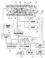
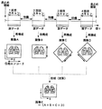
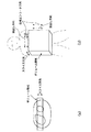
この実施形態にかかるMRI(磁気共鳴イメージング)装置の概略構成を図1に示す。
【0030】
このMRI装置は、被検体Pを載せる寝台部と、静磁場を発生させる静磁場発生部と、静磁場に位置情報を付加するための傾斜磁場発生部と、RF(高周波)信号を送受信する送受信部と、システム全体のコントロール及び画像再構成を担う制御・演算部と、被検体Pの心電図(ECG)信号を計測する心電計測部とを備えている。
【0031】
静磁場発生部は、例えば超電導方式の磁石1と、この磁石1に電流を供給する静磁場電源2とを備え、被検体Pが遊挿される円筒状の開口部(診断用空間)の軸方向(Z軸方向)に静磁場H0 を発生させる。なお、この磁石部にはシムコイル14が設けられている。このシムコイル14には、後述するホスト計算機の制御下で、シムコイル電源15から静磁場均一化のための電流が供給される。寝台部は、被検体Pを載せた天板を磁石1の開口部に退避可能に挿入できる。
【0032】
傾斜磁場発生部は、磁石1に組み込まれた傾斜磁場コイルユニット3を備える。この傾斜磁場コイルユニット3は、互いに直交するX、Y、Z軸方向の傾斜磁場を発生させるための3組(種類)のx,y,zコイル3x〜3zを備える。傾斜磁場部はさらに、x,y,zコイル3x〜3zに電流を供給する傾斜磁場電源4を備える。この傾斜磁場電源4は、後述するシーケンサの制御のもと、x,y,zコイル3x〜3zに傾斜磁場を発生させるためのパルス電流を供給する。
【0033】
傾斜磁場電源4からx,y,zコイル3x〜3zに供給されるパルス電流を制御することにより、3軸X,Y,Z方向の傾斜磁場を合成して、スライス方向傾斜磁場GS 、位相エンコード方向傾斜磁場GE 、および読出し方向(周波数エンコード方向)傾斜磁場GR の各方向を任意に設定・変更することができる。スライス方向、位相エンコード方向、および読出し方向の各傾斜磁場は、静磁場H0 に重畳される。
【0034】
送受信部は、磁石1内の撮影空間にて被検体Pの近傍に配設されるRF(高周波)コイル7と、このコイル7に接続された送信器8T及び受信器8Rとを備える。後述するシーケンサの制御のもと、この送信器8Tは、磁気共鳴(NMR)を励起させるためのラーモア周波数のRF電流パルスをRFコイル7に供給する一方、受信器8Rは、RFコイル7が受信したMR信号(高周波信号)を受信し、この受信信号に各種の信号処理を施して、対応するデジタルデータを形成するようになっている。
【0035】
さらに、制御・演算部は、シーケンサ(シーケンスコントローラとも呼ばれる)5、ホスト計算機6、演算ユニット10、記憶ユニット11、表示器12、入力器13、および音声発生器16を備える。この内、ホスト計算機6は、記憶したソフトウエア手順により、シーケンサ5にパルスシーケンス情報を指令するとともに、シーケンサ5を含む装置全体の動作を統括する機能を有する。このホスト計算機6によるスキャン制御の一例を後述する図2に示す。
【0036】
シーケンサ5は、CPUおよびメモリを備えており、ホスト計算機6から送られてきたパルスシーケンス情報を記憶し、この情報にしたがって傾斜磁場電源4、送信器8T、受信機8Rの一連の動作を制御する。ここで、パルスシーケンス情報とは、一連のパルスシーケンスにしたがって傾斜磁場電源4、送信器8Tおよび受信器8Rを動作させるために必要な全ての情報であり、例えばx,y,zコイル3x〜3zに印加するパルス電流の強度、印加時間、印加タイミングなどに関する情報を含む。また、シーケンサ5は、受信器8Rが出力するデジタルデータ(MR信号)を入力して、このデータを演算ユニット10に転送する。
【0037】
このパルスシーケンスとしては、フーリエ変換法を適用したものであれば、2次元(2D)スキャンまたは3次元スキャンのものであってもよいし、またそのパルス列の形態としては、SE(スピンエコー)法、FE(フィールド・グラジェントエコー)法、FSE(高速SE)法、EPI(エコープラナーイメージング)法、Fast asymmetric SE法(FSE法にハーフフーリエ法を組み合わせた手法)など、どのようなパルス列であってもよい。
【0038】
また、演算ユニット10は、受信器8Rからシーケンサ5を介して送られてくるMR信号のデジタルデータを入力してフーリエ空間(k空間または周波数空間とも呼ばれる)への原データ(生データとも呼ばれる)の配置、および、原データを実空間画像に再構成するための2次元または3次元のフーリエ変換処理を行うとともに、本発明の特徴の一部を成す画像データの合成処理を行うようになっている。なお、フーリエ変換処理はホスト計算機6に担当させてもよい。
【0039】
画像データの合成処理の好適な一例は、複数フレームの再構成画像データを対応画素毎に加算する処理、または、複数フレームの再構成画像データ間の対応するピクセル毎に最大値を選択する最大値投影(MIP)処理である。なお、加算処理には、単純加算処理、加算平均処理、重み付け加算処理などが含まれる。また、この合成処理の別の例としては、フーリエ空間上で複数フレームの軸の整合をとって原データのまま1フレームの原データに合成するようにしてもよい。
【0040】
記憶ユニット11は、原データおよび再構成画像データのみならず、上述の合成処理が施された画像データを保管することができる。表示器12は画像を表示する。また入力器13を介して、術者が希望するスキャン条件、パルスシーケンス、画像合成法などの情報をホスト計算機6に入力できるようになっている。
【0041】
音声発生器14は、ホスト計算機6又はシーケンサ5から指令があったときに、息止め開始および息止め終了の例えば音声メッセージを発することができる。
【0042】
さらに心電計測部は、被検体Pの体表に付着させてECG信号を検出するECGセンサ17と、このセンサ17の検出信号にデジタル化処理を含む各種の信号処理を施してシーケンサ5に出力するECGユニット18とを備える。このECG信号は、ECG同期スキャンを実行するときにシーケンサ5により用いられ、心時相を表す波形に同期したスキャンに拠るMR原データが収集される。
【0043】
次に、この実施形態のスキャン制御に関する動作を説明する。
【0044】
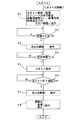
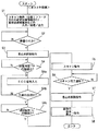
磁石1の診断用空間に患者Pをセットし、MRI装置が起動させると、コントローラ6は所定メインプログラムを実行し、その一環として、図2に示す処理を実行する。
【0045】
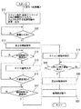
この処理を説明する。同図のステップS1において、コントローラ6は術者が入力器13から指定したスキャン条件(画像サイズ、スキャン回数、スキャン間の待機時間、スキャン部位に応じたパルスシーケンスなど)および画像合成処理法の情報(再構成画像での合成か周波数空間上での合成か、加算処理か最大値投影(MIP)処理かなど。加算処理の場合には、単純加算、加算平均処理、重み付け加算処理のいずれかなど)を入力し、それらの情報を基づいて制御情報に処理し、その制御情報をシーケンサ5および演算ユニット10に出力する。
【0046】
なお、コントローラ6は、このステップS1の処理において、本発明の画像合成を達成するためのスキャン回数(すなわち同一撮像部位に何枚の画像を撮像するか)に応じて、自動的にエンコード方向の変更角度を演算し、スキャン毎のエンコード方向の角度変更情報をパルスシーケンスに組み込んでシーケンサ5に送るようになっている。この角度変更情報は例えば、画像合成を行う画像枚数が2枚の場合、1回目のスキャンが終わって2回目のスキャンを実行するときに、位相エンコード方向を1回目の所定方向から90°変える、というものである。
【0047】
次いでステップS2にてスキャン前の準備完了の指示があったと判断できると、ステップS3で息止め開始の指令を音声発生器14に出力する。これにより、音声発生器14は、「息を止めて下さい」といった内容の音声メッセージを発するから、これを聞いた患者は息を止めることになる(図4参照)。
【0048】
息止め開始を指令した後、コントローラ6はステップS4で所定時間(例えば1秒)の間そのまま待機し、患者が完全に息止め状態になったタイミングを見計らう。
【0049】
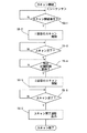
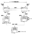
この所定待機時間が経過すると、コントローラ6は処理をステップS5に移行させ、シーケンサ5にスキャン開始を指令する。この指令を受けたシーケンサ5は、既に送られ記憶していたパルスシーケンス情報に応じて送信器8Tおよび傾斜磁場電源4を駆動し、スキャンを実行する。このスキャンの一例に係る処理を図3に、そのタイミングを図4に示す。
【0050】
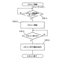
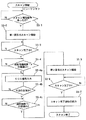
図3に示す処理例はスキャン回数が2回であって、後述する画像合成処理は2枚の再構成画像を加算処理するものである。このスキャン制御例を説明する。
【0051】
シーケンサ5は通常、コントローラ6からスキャンの開始指令が送られてきたか否かを判断しながら待機している(ステップS5−1)。スキャンが指令されると、シーケンサ5は、指令されているエンコード方向に基づく1回目のスキャンを実行する。この1回目のスキャンの場合、例えば、FSE法が選択され、また、位相エンコード方向がZ軸方向に、読出し方向(周波数エンコード方向)がX軸方向に各々設定されている(ステップS5−2:図4参照)。この結果、例えば、肺野のスキャンに伴う1フレーム分のMR原データ(k空間データ)が収集される。
【0052】
このときFSE法によって患者Pから発生したエコ信号は、高周波コイル7で受信され、受信器8Rに送られる。受信器8Rではエコー信号に各種の前処理が施され、デジタル量に変換される。このデジタル量のエコーデータは演算ユニット10に送られ、内蔵メモリに拠る例えば2次元k空間に配置される。このk空間上のエコーデータの組は適宜なタイミングで例えば2次元フーリエ変換して実空間断層像に変換される。この再構成画像データは記憶ユニット11に一時的に格納されて2回目のスキャンを待つ。
【0053】
シーケンサ5は1回目のスキャン指令後、そのスキャンが完了したか否かを判断しながら待機している(ステップS5−3)。
【0054】
この後、シーケンサ5は2回目のスキャンまで所定時間Twの間待機する(ステップS5−4)。この待機時間Twは、1回目のスキャンに拠る原子核スピンの挙動が励起パルス印加前の定常状態まで戻るまで待つことを意図したものである。これにより、2回目のスキャン時の原子核スピンの挙動が1回目のそれに殆ど影響されないから、より忠実なエコーデータが得られる。この待機時間Twとしては、例えば6秒程度のオーダである。なお、術者が入力器13を介して待機時間Twの長短を調節するようにすることも、本発明の望ましい態様の1つである。
【0055】
この待機時間Twが経過すると、シーケンサ5は2回目のスキャンを1回目と同じスキャン面について同様に実行する(ステップS5−5)。ただし、このときの位相エンコード方向は、予め設定されている角度だけ変更されてスキャンが実施される。例えば、1回目の位相エンコード方向から90°ずれた方向に、2回目のスキャン時の位相エンコード方向が設定されている。一例として、位相エンコード方向がX軸方向に、読出し方向(周波数エンコード方向)がZ軸方向に各々変更される。このエンコード状態で2回目のスキャンが実施され(図4参照)、収集されたエコー信号の処理は1回目のときと同じである。
【0056】
そして、シーケンサ5は2回目のスキャン完了が判断できると、スキャン完了の通知をシーケンサ6に対して行う(ステップS5−6,S5−7)。
【0057】
図2のステップS6において待機していたコントローラ6は、シーケンサ5からのスキャン完了通知を受ける。そこで、コントローラ6はステップS7に処理移行させて、息止め解除の指令を音声発生器14に出力する。このため、音声発生器14は、例えば「息をして結構です」といった音声メッセージを患者に向けて発する(図4参照)。
【0058】
この一連のデータ収集処理が終わると、コントローラ6はステップS8にて、演算ユニット10に対して記憶ユニット11に一次格納されている2回のスキャンに拠る再構成画像A,Bの合成処理および表示を指令する。この合成処理の方法は前記ステップS1の入力処理で認識できているから、その方法で画像合成を行って1枚の合成画像Cを生成する。合成処理法としては、いまの場合、2枚の画像A,Bを画素値毎に加算する加算処理や、2枚の画像A,Bの最大値投影処理が使用できる。加算処理の場合、単純加算、加算平均、重み付け加算のいずれかの方法が指令されているので、その方法に沿って行う。この結果、図4に示すように、2枚の再構成画像A,Bから合成画像Cが得られる。
【0059】
このように本実施形態によれば、エンコード方向を変えて収集したエコーデータの複数枚の画像から新規な合成画像を得ることができる。この合成画像はエンコード方向の変更制御に拠って、とくに、T2時間の短めな血流の描出能に優れている。この理由を説明する。
【0060】
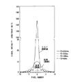
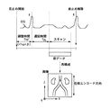
一般に、肺血管や肝臓の血管(門脈)に代表される血流はT2 時間が若干短い(T2 =100〜200ms)ことが知られている。このT2 時間の短めの血流は、T2 時間が長いCSFや関節液(T2 >2000ms)に比べて、信号の半値幅が広がることが分かっている。このことは、例えば、文献「R. Todd Cons- table and John C. Gore, "The loss of small objects in Variable TE ima- ging: Implications for FSE, RARE, and EPI", Magnetic Resonance in Medi- cine 28, 9-24, 1992 」に示されている。同文献によると、T2 時間の異なる物質に対する信号値の広がりは、図5に示すように、“point spread function ”によって表される。同図のグラフは、静磁場=1.5T、TEeff =240ms、エコー間隔(ETS)=12msのときのもので、横軸が位相エンコード方向の画像上の画素数を表し、縦軸が任意単位の信号強度である。これによると、T2 =2000msのCSFや関節液に比べて、T2 =200msの血液(動脈)はその半値幅が広がっている。これは、T2 =200msの血液(動脈)はCSFや関節液よりも、見掛け上、1画素当たりの位相エンコード方向の幅が伸びているのと等価であると言える。したがって、T2 =200msの血液(動脈)は、CSFや関節液に比べて、画像全体が位相エンコード方向に余計にぼけることを示している。
【0061】
本発明は、T2 時間が短い血液の位相エンコード方向の信号値のピクセル上の広がり(ぼけ)の度合いが、T2 時間が長いものよりも大きいことを積極的に利用したものである。
【0062】
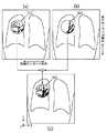
これを図6で模式的に説明する。図6に示すように、血管B1からその直交方向に枝分かれした血管B11があって、例えば1回目のスキャン時の位相エンコード方向が血管B1の走行方向に略一致し、2回目のスキャン時の位相エンコード方向が枝分かれした血管B11に略一致しているとする。同図(a)に示すように、1回目のスキャンに拠る位相エンコード方向の信号値の広がりに拠って各画素が疑似的に伸びたものと等価になり、その位相エンコード方向と略一致している血管B1はぼけに因って強調され、反対に、これに直交する方向の血管B11はぼけてしまう。しかし、2回目のスキャンでは位相エンコード方向が90°変更されるので、今度は反対に同図(b)に示すように、一方の血管B1はぼけるが、もう一方の血管B11はぼけに因って強調される。
【0063】
本発明を具体化した上述した実施形態では、同図(a)および(b)の再構成画像が画素毎に加算(合成)されるので、同図(c)に示す如く、両方の位相エンコード方向の血流B1,B11の画像が共に消失されずに残る。しかも、位相エンコード方向にぼけるとはいえ、加算処理の場合には、2枚の画像を画素毎に加算しているからアベレージング法の利点も享受でき、併せて血流の信号値を上げ、S/Nを向上させる。図6では直交する2方向についてのみ説明したが、血流B1が1回目の位相エンコード方向から多少ずれていても、また血流B11が2回目のそれから多少ずれていても、かかる利点を多少とも享受できる。したがって、縦横無尽に走行している肺血管などの血管に対し、その走行方向情報を殆ど欠落させることなく、高いS/Nおよび実質部の高いコントラストで描出することができ、診断能の向上に寄与可能になる。
【0064】
従来の位相エンコード方向が固定のアベレージング法の場合には、S/N比向上は見込めるものの、例えば図6(a)に示す方向に位相エンコード方向を設定したときには、血流B11が位相エンコード方向のぼけに因って目視で識別困難になるか、または、消失してしまうことがあった。また図6(b)に示す方向に位相エンコード方向を設定したときには、血流B1が同様の問題に直面していた。しかしながら、本発明によって、そのような状態を回避し、とくに、肺野や肝臓の血管などT2 時間が短めの血管についてその走行方向の情報量を低下させることなく描出することができるようになった。
【0065】
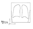
図7に、本発明に基づいて本発明者が行った実験で得たコロナル像の写真の一部(図中の丸円CL内の部分)を手で模写した図を示す。同図(a)では位相エンコード方向はZ軸方向に、かつ、読出し方向はX軸方向に設定され、また同図(b)ではそれらの方向が反対に設定されている。両方の図とも、スライス方向はY軸方向に設定されている。この実験は、2D Fast Asymmetric SE法(TEeff =120ms,ETS=5ms,ショット数=1,ST(スライス厚)=30mm,NS=1,256×256,35×35cm,実際のスキャン時間=760msで、第1スキャン開始から第2スキャン開始までの時間差4000msで位相エンコード方向を同図(a),(b)に示す如く2方向に変えて肺野、門脈のMRA描出能を評価したものである。
【0066】
同図(a),(b)の肺野と門脈に注目すると、それぞれ示した位相エンコード方向に血流が伸びていることが明瞭に分かる。これに対して、同図(a), (b)の画像を加算処理した同図(c)の画像では、血管の走行状態が上下左右に共に伸びていることが明瞭に分かる。つまり、同図(c)の画像の方が血管の走行方向の情報を豊富に提供しており、実際のものを的確に反映している。これによって、本発明の手法に係る同図(c)の画像が、従来の画像(同図(a)または(b)をアベレージングした画像)よりも優位であることが認められ、本発明の効果が顕著であることが確認された。
【0067】
ところで、上述した実施形態の場合、1回の息止め期間に2回全部のスキャンを終えるようにしている。このため、肺などの周期的運動による体動アーチファクトの発生を抑制できるとともに、複数回にわたって息止め撮像をするときの患者の体自体の位置ずれに因る体動アーチファクトの発生も合わせて低減できる。これにより、アーチファクトのより少ない高品質の画像を提供できる。
【0068】
また、2回のスキャンの間にスピンの回復を待つ待機時間を設定しているから、2回目のスキャンもより的確に実行でき、高品質の画像を提供できる。
【0069】
さらに、そのような待機時間を設定したとしても、多くの場合、1回目、2回目のスキャンは1.5秒程度、待機時間は4秒程度で済むので、息止めの期間は6秒ちょっとで済む程度である。したがって、患者の1回の息止めの継続時間は短くて済み、子供や老人にとっても、息止めの関する精神的、体力的負担軽いという利点もある。
【0070】
第2の実施形態
本発明の第2の実施形態を図8に基づき説明する。なお、この実施形態を含め、これ以降の実施形態において、上述した第1の実施形態の構成要素と同一または同等のものについては同一符号を用い、その説明を省略または簡略化する。
【0071】
この第2の実施形態に係るMRI装置では、位相エンコード方向を変えて実行する複数回のスキャンの内、1回目のスキャンの位相エンコード方向を、画像化したい主たる血管の走行方向に積極的(意図的)に合わせるイメージングが実施される。
【0072】
例えば、図8に示すように、α度斜めに走行している門脈を主に観察したい場合、ホスト計算機6は、X軸、Y軸、およびZ軸方向の傾斜磁場の強度をそれぞれ調整して合成された位相エンコード用傾斜磁場の方向がα度斜めになるようにシーケンサのパルスシーケンス情報を送る。これにより、位相エンコード方向をα度斜めの方向に設定したスキャンが実施される。また、ホスト計算機6からの指令により、位相エンコード方向を別の角度に設定した別のスキャンが実施され、全部で複数回のスキャンが異なる位相エンコード方向の元で実施される。
【0073】
これにより、α度斜めに走行している観察したい血管は、画像上で前述した画素のボケに因って必ず強調される。同時に、α度斜め以外の残りの方向に走行している血管も、α度斜め以外の方向に設定した位相エンコード方向の元でのスキャンによって適宜に強調される。つまり、選択した所望の方向に走行している診断的に重要な血管は必ず強調される一方で、それ以外の方向に走行している血管も多少とも同時に強調される。とくに、1回目のスキャンの位相エンコード方向を、画像化したい主たる血管の走行方向に積極的(意図的)に合わせることで、サチュレーション効果が低減されるという効果も得られる。
【0074】
また、このイメージングを実施する傾斜磁場のパルス波形は比較的簡単に設計でき、傾斜磁場パルス波形の複雑な設計を必要とする、流れを補償する技法(例えば、“R.S.Hinks et al, Magn. Reson. Med.(MRM) 32:698-704(1994)”参照)を用いる必要もなくなる。
【0075】
第3の実施形態
本発明の第3の実施形態を説明する。上述した実施形態は位相エンコード方向を変えて2回のスキャンを行うものであったが、本発明にこれに限定されるものではない。例えば、図9に示すように、位相エンコード方向を変えて4回のスキャンを順次、所定待機時間毎に実施し、これにより45°ずつ位相エンコード方向が異なった4フレーム分のMR原データを得る。この4回のスキャンは、ホスト計算機6がシーケンサ5に渡すパルスシーケンス情報に拠って制御される。
【0076】
収集された原データをそれぞれのフレームで画像再構成し、4枚の再構成画像を合成処理(加算処理または最大値投影処理)を行うものである。これによっても、上述した実施形態のものと同等またはそれ以上に、位相エンコード方向のより細かい角度制御に拠って、血管の走行情報が豊富なMR画像を得ることができる。
【0077】
なお、図9に示す位相エンコード方向の複数回の採り方をさらに発展させることもできる。例えば、位相エンコード方向を22.5°ずつ8通りに変えて8回のスキャンを順次、所定待機時間毎に実施し、これに基づき位相エンコード方向が異なった8フレーム分のMR原データから同様の合成処理を行うこともできる。すなわち、本発明の手法に拠り加算(合成)する画像枚数n(すなわち位相エンコード方向の変更回数)はn≧2であればよい。
【0078】
なお、上述した第2及び第3の実施形態の変形例として、位相エンコード方向をある基準方向から等分に変えていくのではなく、所望の複数方向を任意に選んでそれぞれを位相エンコード方向に設定することもできる。
【0079】
第4の実施形態
本発明に係る第4の実施形態を図10〜図12に基づき説明する。
【0080】
この実施形態は、位相エンコード方向を1方向のみに設定する手法(したがって、前述した画像データの合成処理は行わない)とECG同期法とを組み合わせて実施するスキャン法に関する。
【0081】
これを実現するため、ホスト計算機6およびシーケンサ5は図10および図11に示す処理をそれぞれ実行する。
【0082】
まず、ホスト計算機6により実行される図10の処理を説明する。同図のステップS11において、ホスト計算機6は、スキャン条件(例えば、画像サイズ、1回の位相エンコード方向の情報、およびスキャン領域に応じたパルスシーケンス)を入力し、それらの入力情報にしたがって制御情報を用意し、さらに、その制御情報をシーケンサ5および演算ユニット10に出力する。
【0083】
次いで、ステップS12にてスキャン前の準備完了の指示があったと判断できると、ステップS13で前述と同様に、息止め開始の指令が音声発生器14に出力される。
【0084】
さらに、ステップS14で、所定の調整時間Tspが経過したか否かを判断しながら待機する。この待機の後、ステップS15,16の処理が順次行われる。つまり、シーケンサ5を介してECG信号がホスト計算機6に読み込まれ(ステップS15)、ECG信号のR波が出現したか否かが判断される(ステップS16)。すなわち、最初のR波の出現が検知されたときは、息止め開始指令後の経過時間がTsp′(=Tsp+β、ここでβは任意の時間:図12参照)になる。
【0085】
この最初のR波が出現した後、ホスト計算機6は、さらに適宜な遅延時間TDLの経過を判断しながら待機する(ステップS17)。この遅延時間TDLは、心収縮によって生じる、R波の出現中および出現直後における血流の不安定時間帯を回避するために設定されるもので、700〜1000msec程度の心周期に対して、例えばTDL=500msec程度の適宜な値に予め設定されている。このように遅延時間TDLを適宜な値に設定することで、拡張期の比較的安定した時間帯に収集されるエコーデータを、k空間の位相エンコード方向の中心部(すなわち、低周波領域)に配置することができる。このため、1回のスキャンが次の1つまたは複数の心拍に渡って継続される場合でも、収縮期に収集されるエコーデータをk空間の位相エンコード方向における端の領域または端寄りの領域(すなわち、高周波領域)に配置することができる。これにより、再構成された実空間の画像は高コントラストおよび高画質になる。
【0086】
ステップS17の処理で遅延時間TDLが経過したと判断されると、ステップS18およびステップS19の処理が順に続く。つまり、第1の実施形態のときと同様に、ホスト計算機6は、シーケンサ5にスキャン開始を指令し(ステップS18)、さらに、シーケンサ5からスキャン完了の通知があったか否かを判断しながら待機する(ステップS19)。シーケンサ5は、スキャン開始の指令に応答して図11に示すステップS18−1〜4の処理を行う。これにより、指令された位相エンコード方向の元で、1回のスキャンにより、1組のMR原データが収集される。
【0087】
この1回のスキャンが完了したとき、ホスト計算機6は息止めの解除およびスキャンにより得た再構成画像の表示を指令する(ステップS20,S21)。このエコーデータ収集後の処理において、前述したような画像データの合成を指令する必要はない。
【0088】
図12に、この実施形態に係るタイミングチャートの一例を示す。ここでは、ある1つの位相エンコード方向においてのみMR原データの収集が収集される。このため、このスキャン法は、被検体内の画像化したい血管の走行方向が既知であるか、または、前もって推定できるときに使用することが望ましく、例えば、下腹部の血管の画像化に好適である。このスキャン法を用いて撮像する場合、位相エンコード方向は血管の既知の走行方向または推定方向に合わせられる。これによっても、前述した画像合成の処理を行わないが、前述したと画素のぼけの原理の積極的利用によって、再構成画像上での画像化を意図した血管を強調させることができる。
【0089】
さらに、ECG同期法を併用しているので、コントラストが高く且つ安定したMR像を提供できるという利点がある。とくに、R波とスキャン開始との間を規定する遅延時間TDLを適宜に調整することで、スキャン全体の時間帯を、心筋の収縮に因る血流の乱れを回避できる時間的位置に設定することができる。このため、スキャンの初めの方の時間帯で収集したエコーデータはk空間の位相エンコード方向の中心部に配置され、再構成に供される。この中心部に配置されるエコーデータの信号強度が再構成画像のコントラストを決めるが、この実施形態によれが、高強度のエコーデータが位相エンコード方向の中心部に配置されるため、コントラストの高い、かつ安定した高画質のMR像を提供できる。
【0090】
また、前述した息止め法の利点、および、スキャンが1回であることの利点、すなわち撮影時間の短縮化の利点も同様に享受することができる。
【0091】
第5の実施形態
本発明の第5の実施形態を図13〜図15を参照して説明する。
【0092】
この実施形態に係るMRI装置は、前述した第1の実施形態で説明したイメージング法にECG同期法を採用したことを特徴とする。
【0093】
具体的には、ホスト計算機6が図13に示す処理を行い、シーケンサ5が図14に示す処理を行うようにそれぞれ設定されている。これらの図において、新しく追加したステップS4a〜S4c、S5−4a〜S5−4c以外の処理は先に説明した図2、3のものと同一または同等である。
【0094】
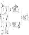
図13のステップS4およびS4a,S4bにおける処理によって、図15に示す如く、息止め開始時刻と所定期間Tspの経過後に最初に現れるR波との間に調整時間Tsp′(=所定時間Tsp+任意の時間β)を設定することができる。さらに、ステップS4cの処理がホスト計算機6により実行されると、図15に示すように、第1回目のスキャンの前にECG同期用の指定遅延時間TDLが設定される。
【0095】
さらに、図14のステップS5−4aおよびS5−4bの処理によって、図15に示す如く、第1回目のスキャンの終了時と所定の待機時間Twが経過した後で最初に現れるR波との間に、待機時間Tw′(=所定の待機時間Tw+任意の時間β)が設定される。またステップS5−4cの処理が実行されると、図15に示す如く、第2回目のスキャンの前にECG同期用の指定遅延時間TDLが設定される。
【0096】
その他の処理は図2、3と同様または同一である。
【0097】
このため、前述したように、ECG同期法を併用することで、画像のコントラストをさらに向上させることができる。
【0098】
第6の実施形態
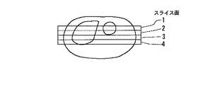
本発明の第6の実施形態を図16〜17を参照して説明する。この実施形態は、本発明の撮像法を3次元撮像に適用したことを特徴とする。
【0099】
この3次元撮像(3Dスキャン)の場合、スライス方向を不変とした状態で、位相エンコード方向と読出し方向をスキャン毎に交換しながら、すなわち位相エンコード方向を90度変更して複数回のスキャンが実行される。
【0100】
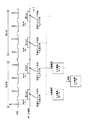
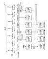
具体的には、図16が、ホスト計算機6によって指令される3Dスキャンに係るデータ収集シーケンスの一例を示す。この3Dスキャンでは、位相エンコード方向を90度変える手法のほか、心電同期および息止めの手法も併用されている。心電同期タイミングは予め最適化された遅延時間TDLで決められる。例えば、図17(a),(b)に示す如く腹部を3次元撮像する場合のボリューム領域のデータ収集は、位相エンコード方向がRLse1 ,HFse1 ,RLse2 ,HFse2 ,…,RLsen ,HFsen の順序で(RL:左右方向、HF:上下方向)各回のスキャンが2n回(nは2以上の整数)、例えば「Fast Asymmetric SE法」で実施される。
【0101】
図中のスキャンRLsen またはHFsen は、共に、スライスエンコード傾斜磁場の各スライスエンコード量に対する1回のスキャンを表す。しかし、スキャンRLseとスキャンHFseでは位相エンコード方向が異なる。スキャンRLseの場合、図17(b)の実線矢印X1で示すように、位相エンコード方向が患者の体の左右方向に設定される。これに対し、スキャンHFseの場合、同図の点線矢印X2で示すように、位相エンコード方向は患者の上下(頭部/脚部)方向に設定され、左右方向とは90度異なる。添字se1…senは、各スキャンに対するスライスエンコードの傾斜磁場量を表す。この例示シーケンスでは、同一のスライスエンコード量se1(…sen)について2回の3Dスキャンが心電同期法の元に実施され、この2回の3Dスキャンがスライスエンコード量を変えながら順次繰り返され、撮像全体としては、左右方向と上下方向の位相エンコード方向が入れ子方式で続く。この3Dスキャンの場合、全体の撮像時間は比較的長くなるので、息止めは複数回に別けて実施される。
【0102】
画像再構成は、位相エンコード方向が左右方向に設定されて収集された3次元原データの1組で、また位相エンコード方向が上下方向に設定されて収集された3次元原データの別の1組で個別に実施される。両方の3次元の再構成データは画素毎に合成され、最終的な3次元のMRAデータとなる。
【0103】
この3次元イメージングによっても、前述した実施形態のものと同等に、最適化された心電同期タイミングによる描出能の向上を初めとして、血流の方向性の情報の確保などの作用効果を得ることができる。
【0104】
第7の実施形態
本発明の第7の実施形態を図18〜19を参照して説明する。この実施形態は、本発明の撮像法をマルチスライス撮像に適用したものである。
【0105】
図18はホスト計算機6により指令されるマルチスライススキャンのデータ収集シーケンスを例示している。このシーケンスでは、第6の実施形態と同様に、位相エンコード方向の制御、心電同期、および1回息止めの各手法が採用されている。心電同期の同期タイミングは、予め実施する準備スキャンなどを通して最適化された遅延時間TDLで決められる。
【0106】
例えば、4枚のマルチスライススキャンで腹部を撮像する場合、図19に示す如く、スキャンRL1,RL2,RL3,RL4,HF1,HF2,HF3,HF4の順序で例えば「Fast Asymmetric SE法」に基づきデータ収集される。第6の実施形態と同様に、スキャンRLは位相エンコード方向が左右方向、スキャンHFはそれが上下方向であることを示し、各回のスキャンにより各スライスの2次元原データが生成される。互いに位相エンコード方向が90度異なる2フレームの再構成画像データが画素毎に合成され、各スライスのMRA像データが作成される。このため、高い血流方向の検出能が確保される。また、当然に、前述した心電同期や息止めの効果もこのマルチスライススキャンにおいて併せて発揮される。このマルチスライススキャンのスキャン順序は、RL1,HF1,RL2,HF2,…といった具合に任意に変更してもよい。
【0107】
なお、第4の実施形態以外の実施形態で説明した手法を3Dスキャンに適用するときの変形例として、前述の如くスライスエンコード方向を固定として位相エンコード方向を切り換える場合の他に、リード方向を固定して位相エンコード方向を切り換えるようにしてもよく、また、x,y,z方向をそれぞれ位相エンコード方向として画像合成するようにしてもよい。
【0108】
なお、上述した各種の実施形態変形例は、血管の画像を得るMRアンギオグラフィ(MRA)を目的とした装置および撮像法を説明したが、撮像対象は血管のみに限定されず、繊維状に走行する組織等、任意の対象のものであってよい。とくに、T2 時間が短めなものであれば、本発明に係るスキャンを好適に実施できる。
【0109】
【発明の効果】
以上説明したように、本発明のMRI装置によれば、アベレージング法に拠り血管、組織などを撮像する場合、それらの撮像対象からの信号値を上げて良好なS/Nを維持するとともに、撮像対象の多様な走行方向の情報を的確に確保でき、方向性の描出能が従来よりも格段に優れたMR画像を得ることができる。とくに、T2時間がT2=100〜200msと短めの血流や組織を撮像するときに、その効果が著しく発揮される。その一方で、位相エンコード方向を撮像対象の走行方向に合わせることで、その方向の優れた描出能を得ることができる。また、これらの優れた方向性描出能を発揮する撮像法に、1回の息止め法を併用することができるので、患者の体力的、精神的負担も少なく、体動アーチファクトの少ない、高品質、かつ診断能向上に寄与できるMR画像を得ることができる。さらに、それらの優れた方向性描出能を発揮する撮像法を3次元撮像やマルチスライス撮像に適用でき、そのイメージング機能の充実化、豊富化を図ることができる。
【図面の簡単な説明】
【図1】本発明の実施形態に係るMRI装置の一例を示すブロック図。
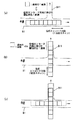
【図2】第1の実施形態における撮像手順例を示す概略フローチャート。
【図3】第1の実施形態におけるスキャン制御例を示す概略フローチャート。
【図4】第1の実施形態における複数回のスキャンの順序と画像合成の関係を模式的に説明する図。
【図5】位相エンコード方向の信号値の広がりを説明する図。
【図6】単独スキャン時の位相エンコード方向の信号値の広がりによる画像とそれらの画像の合成時の状態との関係を示す模式図。
【図7】本発明の効果を示す実験例による肺野および肝臓のMRA画像の一部を模写して本発明の効果を説明する図。
【図8】第2の実施形態に係る撮像における第1回目のスキャンの位相エンコードの設定例を模式的に説明する図。
【図9】第3の実施形態における複数回のスキャンの順序と画像合成の関係を模式的に説明する図。
【図10】第4の実施形態における撮像手順例を示す概略フローチャート。
【図11】第4の実施形態におけるスキャン制御例を示す概略フローチャート。
【図12】第4の実施形態におけるスキャンのECG同期タイミングとデータ収集とを模式的に説明する図。
【図13】第5の実施形態における撮像手順例を示す概略フローチャート。
【図14】第5の実施形態におけるスキャン制御例を示す概略フローチャート。
【図15】第5の実施形態における複数回のスキャンのECG同期タイミング、データ収集、および画像合成の処理とを模式的に説明する図。
【図16】第6の実施形態における複数回のスキャンのECG同期タイミング、データ収集、および画像合成の処理とを模式的に説明する図。
【図17】第6の実施形態における撮像領域としてのボリューム領域と位相エンコード方向の制御の関係を模式的に説明する図。
【図18】第7の実施形態における複数回のスキャンのECG同期タイミング、データ収集、および画像合成の処理とを模式的に説明する図。
【図19】第6の実施形態における撮像領域としてのマルチスライスを模式的に説明する図。
【符号の説明】
1 磁石
2 静磁場電源
3 傾斜磁場コイルユニット
4 傾斜磁場電源
5 シーケンサ
6 ホスト計算機
7 RFコイル
8T 送信器
8R 受信器
10 演算ユニット
11 記憶ユニット
12 表示器
13 入力器
16 音声発生器
17 ECGセンサ
18 ECGユニット[0001]
BACKGROUND OF THE INVENTION
The present invention relates to magnetic resonance imaging for imaging the inside of a subject based on the magnetic resonance phenomenon of the subject. In particular, the lateral relaxation of the nuclear spin of the specimen (T2Suitable for imaging tissue or blood flow with a short relaxation timeFor MRI (magnetic resonance imaging) equipmentRelated.
[0002]
[Prior art]
Magnetic resonance imaging magnetically excites a subject's nuclear spin placed in a static magnetic field with a high-frequency signal of its Larmor frequency, and reconstructs an image using the MR signal generated by this excitation, This is a technique for obtaining an MR spectrum.
[0003]
There are various requirements when imaging blood vessels in the lung field, blood vessels in the liver (portal vein), and the like by this magnetic resonance imaging. One of them is to increase the signal value of the blood vessel image to improve the S / N ratio, and another requirement is to reduce artifacts due to body movement.
[0004]
As a method of increasing the former signal value, there is a method of averaging (addition averaging) n (> 1) MR data for each pixel. In order to perform this averaging process, the number of shots and the number of times of imaging are increased to increase the number of data for each pixel, and the number of integrations at each pixel is increased. When performing this averaging process, conventionally, the phase encoding direction at the time of MR signal acquisition is always set to a constant direction.
[0005]
In order to suppress the occurrence of the latter body motion artifact, there is a method in which the patient holds a breath. As a result, body motion artifacts due to lung motion can be reduced. However, when generating an image from MR data obtained by collecting data during each breath holding period over a plurality of breath holding periods, the influence of body movement artifacts caused by the movement of the patient's body position itself is affected. As a result, blurring may occur in the image. For this reason, breath holding is normally performed only once, and efforts are made to increase the number of integrations for the averaging method during this one breath holding.
[0006]
[Problems to be solved by the invention]
However, particularly in imaging using a pulse sequence such as the FSE method and the EPI method, even when the conventional one-time breath-holding and averaging methods described above are employed, T2Shorter time (T2= 100-200ms) (the blood flow, especially the blood vessels of the lung field, the blood vessels of the liver (portal veins) or the vasculature, etc.) cannot be displayed well, and I was dissatisfied with the ability to draw. It was.
[0007]
This is the T2This is because the full width at half maximum of the MR signal generated from a component having a short time (hereinafter simply described as blood flow) spreads (extends) in the phase encoding direction, and the entire image is blurred in the phase encoding direction. When the image is blurred in the phase encoding direction, the pixel value of the blood flow image that intersects (or is orthogonal to) the phase encoding direction is averaged with that of the surrounding tissue, and the resolution is lowered. That is, on the image, it is difficult to distinguish a blood flow image traveling in the direction intersecting the phase encoding direction from the surrounding tissue.
[0008]
When MR data in which the phase encoding direction is determined to be a predetermined direction is subjected to averaging processing, the resolution of the blood flow traveling in the phase encoding direction is improved. However, for blood flow images traveling in other directions, the resolution remains low because the blurred pixels are simply averaged.
[0009]
Therefore, in the case of conventional averaging, it has been difficult to obtain an image that clearly shows the traveling direction of a blood flow image traveling indefinitely and horizontally without losing traveling information. In other words, blood flow images in directions other than phase encoding tend to be lost from the image, and may not be observed even if the image is watched. This problem is especially true for T2Time was noticeable with shorter blood flow.
[0010]
The present invention has been made in order to overcome the current state of the prior art. Specifically, when imaging a blood vessel or the like, the object of the present invention is to increase the signal value from the blood flow to maintain a good S / N and to change the traveling direction of the blood vessels traveling in various directions. Secure information and obtain images with excellent rendering abilityMRI equipmentTo provide.
[0011]
Another object of the invention is in particular T2Time T2= When imaging a short blood flow of 100 to 200 ms, the signal value from the blood flow is increased to maintain a good S / N, and information on the directionality of the blood flow traveling in various directions is obtained. It is possible to obtain an image with excellent rendering ability.
[0012]
Yet another object of the present invention is to ensure that such excellent imaging capability can be applied to multi-slice imaging and three-dimensional imaging.
[0013]
Yet another object of the present invention is to allow such superior imaging capabilities to be used in conjunction with a single breath-holding technique.
[0014]
[Means for Solving the Problems]
In order to achieve the above object, the MRI apparatus according to the present invention collects echo signals by controlling gradient magnetic fields in the phase encoding direction, readout direction, and slice direction with respect to a subject, and obtains MR images from the echo signals. In the MRI apparatus, the predetermined imaging region of the subject is changed by changing the phase encoding direction.In multiple scans to be executed, the phase encoding direction is imaged in accordance with the traveling direction of the branching blood vessel.Scanning means for generating a plurality of image data based on the plurality of MR data, and generating a single image data by combining the plurality of image data, and the scanning means includes a cardiac phase Timing determining means for determining the start timing of each of the plurality of scans based on a signal representing a cardiac time phase detected by the detection means; and scan execution means for executing each scan in synchronization with the start timing The main configuration is that
[0015]
With this main configuration, the phase encoding direction is changed variously and a plurality of scans are performed, and image data is obtained from the data of a plurality of sets of echo signals obtained thereby by, for example, addition processing for each pixel. In this image data, the blur of the pixel value in the phase encoding direction set in each scan is positively reflected. For this reason, even if the traveling directions of blood and tissue to be imaged are variously different, there is little lack of information on the traveling direction, and MR images with excellent rendering performance and good S / N can be provided.
[0016]
The main configuration described above can be developed in various configurations. For example, the generating means reconstructs the plurality of sets of MR original data into real-space image data for each set, and the plurality of sets of reconstructed image data into one set of image data. Synthesizing means for synthesizing. In this case, for example, the synthesizing unit is a unit that synthesizes the one set of image data by performing one of a adding process and a maximum value projecting process on the plurality of sets of reconstructed image data for each pixel. It is.
[0017]
The scanning means may be means for executing the plurality of scans within a duration of one breath holding of the subject. In this case, the scanning unit may include a breath holding notification unit that notifies the subject of a start time and a release time of the breath holding.
[0018]
Furthermore, in the various configurations described above, the scanning unit includes a standby unit that sets a predetermined standby time between the plurality of scans and restores the nuclear spin of the imaging region of the subject to a steady state. You may comprise as follows.
[0019]
In the main configuration, as a preferred specific example, the scanning unit may be a unit that obtains MR original data for two frames by sequentially performing two scans by changing the phase encoding direction by 90 °. Further, the scanning means may be means for obtaining MR original data for n frames by changing the phase encoding direction n times (n is an integer of 3 or more) and sequentially performing n scans.
[0020]
Furthermore, as another preferred specific example, the subjectPredeterminedThe imaging region is a single two-dimensional slice whose slice position is determined by a slice gradient magnetic field applied in the slice direction, or a multi-slice region composed of a plurality of two-dimensional slices. In addition, the subjectPredeterminedThe imaging region can be applied even in a three-dimensional region where a slice encoding gradient magnetic field is applied in the slice direction.
[0021]
More preferably,The cardiac phase detection meansMay comprise means for collecting the ECG signal of the subject as a signal representing the cardiac time phase. For example, the timing determining means is a means for determining the start timing with a predetermined delay time from the R wave. In this case, the predetermined imaging region of the subject may be a multi-slice region including a plurality of two-dimensional slices whose slice positions are determined by a gradient magnetic field for slice applied in the slice direction. The scan execution means performs a sequence of executing the scan individually in synchronization with the R wave based on the same phase encoding direction set in a predetermined direction with respect to the plurality of two-dimensional slices. It is desirable that the encoding direction be changed to another direction and repeated.
[0022]
In addition, the subjectPredeterminedThe imaging region may be a three-dimensional region to which a slice encoding gradient magnetic field is applied in the slice direction. In the case of this three-dimensional region, the scan execution unit sets the three-dimensional region in a predetermined direction. A sequence for executing the scan a plurality of times in synchronism with the R wave under the same phase encoding direction, and the same phase encoding direction set in a direction different from the predetermined direction with respect to the three-dimensional region It is preferable that the means adopts a sequence in which a sequence in which the scan is executed a plurality of times in synchronization with the R wave is nested in a time series.
[0023]
As another specific example of the main configuration, the phase encoding direction for the first scan of the plurality of scans is designated in advance according to the traveling direction of the imaging target in the imaging region of the subject. The scanning unit may include a specifying unit, and the scanning unit may include a unit that executes the first scan based on the specified phase encoding direction.
[0024]
As another configuration of the MRI apparatus of the present invention, an MRI apparatus that collects echo signals by controlling gradient magnetic fields in a phase encoding direction, a reading direction, and a slice direction with respect to a subject and obtains an MR image from the echo signals. , Specifying means for specifying in advance the phase encoding direction according to the traveling direction of the imaging target in the imaging region of the subject, and based on the specified phase encoding direction, Image the phase encoding direction to match the traveling direction of the branching blood vesselScanning means, and the scanning means determines the start timing of each of the plurality of scans based on a signal representing the cardiac phase detected by the cardiac phase detection means, and the start Scan execution means for executing each of the scans in synchronism with timing. As a result, it is possible to perform imaging with excellent rendering ability in the running direction of blood vessels and tissues that positively uses the blur of pixel values in the phase encoding direction.
[0025]
Furthermore, another configuration of the MRI apparatus of the present invention includes a static magnetic field generation unit that generates a static magnetic field having a constant intensity, and a gradient magnetic field in a phase encoding direction, a readout direction, and a slice direction on a subject placed in the static magnetic field. A gradient magnetic field generator for applying a pulse to the subject, a transmission / reception unit for transmitting a high-frequency signal to the subject along with the gradient magnetic field and receiving an echo signal generated from the subject, and an operation for processing the echo signal And the gradient magnetic field generation unit, the transmission / reception unit, and the calculation unit are controlled based on a predetermined algorithm to magnetically scan the imaging region of the subject, and the echo signal generated based on the scan And a controller for acquiring MR images, wherein the algorithm scans a predetermined imaging region of the subject a plurality of times by changing the phase encoding direction. A plurality of echo signals are collected, a plurality of image data are respectively created from the plurality of echo signals, and the plurality of image data are combined to generate one image data. A configuration is provided in which the start timing of each of the plurality of scans is determined based on a signal representing the cardiac phase detected by the phase detection means, and each of the scans is executed in synchronization with the start timing. It is what. Since the control unit performs control based on the algorithm, it is possible to perform imaging with excellent visualization of the running direction of blood vessels and tissues that positively uses blurring of pixel values in the phase encoding direction.
[0027]
DETAILED DESCRIPTION OF THE INVENTION
Embodiments of the present invention will be described below with reference to the accompanying drawings.
[0028]
First embodiment
A first embodiment will be described with reference to FIGS.
[0029]
A schematic configuration of an MRI (magnetic resonance imaging) apparatus according to this embodiment is shown in FIG.
[0030]
This MRI apparatus includes a bed unit on which a subject P is placed, a static magnetic field generating unit for generating a static magnetic field, a gradient magnetic field generating unit for adding position information to the static magnetic field, and transmission and reception for transmitting and receiving RF (high frequency) signals. A control unit that controls the entire system and image reconstruction, and an electrocardiogram measurement unit that measures an electrocardiogram (ECG) signal of the subject P.
[0031]
The static magnetic field generation unit includes, for example, a
[0032]
The gradient magnetic field generator includes a gradient magnetic
[0033]
By controlling the pulse currents supplied from the gradient magnetic
[0034]
The transmission / reception unit includes an RF (high frequency)
[0035]
The control / arithmetic unit further includes a sequencer (also referred to as a sequence controller) 5, a
[0036]
The
[0037]
The pulse sequence may be a two-dimensional (2D) scan or a three-dimensional scan as long as the Fourier transform method is applied, and the pulse train may have an SE (spin echo) method. , FE (Field Gradient Echo) method, FSE (Fast SE) method, EPI (Echo Planar Imaging) method, Fast asymmetric SE method (method combining FSE method with half Fourier method) May be.
[0038]
The
[0039]
A preferred example of the image data combining process is a process of adding reconstructed image data of a plurality of frames for each corresponding pixel, or a maximum value for selecting a maximum value for each corresponding pixel between the reconstructed image data of a plurality of frames. Projection (MIP) processing. The addition processing includes simple addition processing, addition averaging processing, weighted addition processing, and the like. As another example of the synthesis process, the alignment of the axes of a plurality of frames may be taken in Fourier space, and the original data may be synthesized into one frame of original data.
[0040]
The
[0041]
The
[0042]
Further, the electrocardiogram measurement unit attaches to the body surface of the subject P and detects an ECG signal, and performs various signal processing including digitization processing on the detection signal of the
[0043]
Next, operations relating to scan control of this embodiment will be described.
[0044]
When the patient P is set in the diagnostic space of the
[0045]
This process will be described. In step S1 in the figure, the
[0046]
Note that, in the process of step S1, the
[0047]
Next, when it is determined in step S2 that there is an instruction for completion of preparation before scanning, a command to start breath holding is output to the
[0048]
After commanding the start of breath holding, the
[0049]
When the predetermined waiting time has elapsed, the
[0050]
In the processing example shown in FIG. 3, the number of scans is two, and an image composition process to be described later adds two reconstructed images. An example of this scan control will be described.
[0051]
The
[0052]
At this time, the eco signal generated from the patient P by the FSE method is received by the
[0053]
After the first scan command, the
[0054]
Thereafter, the
[0055]
When the standby time Tw elapses, the
[0056]
When the
[0057]
The
[0058]
When this series of data collection processing is completed, the
[0059]
As described above, according to this embodiment, a new composite image can be obtained from a plurality of images of echo data collected by changing the encoding direction. This composite image is based on the control of changing the encoding direction.2Short-time blood flow visualizationAre better. The reason for this will be explained.
[0060]
In general, blood flow represented by pulmonary blood vessels and liver blood vessels (portal veins) is T2Time is slightly shorter (T2= 100 to 200 ms). This T2The shorter blood flow is T2CSF and joint fluid (T2It has been found that the full width at half maximum of the signal is wider than (> 2000 ms). This can be seen, for example, in the literature “R. Todd Cons-table and John C. Gore,“ The loss of small objects in Variable TE imaging—Fplication, FARE, RARE, and EPI ”, Magnetic Resonance in Medicine 28. , 9-24, 1992 ". According to the document, T2As shown in FIG. 5, the spread of signal values for substances with different times is represented by “point spread function”. The graph in the figure is for a static magnetic field = 1.5 T, TEeff = 240 ms, echo interval (ETS) = 12 ms, the horizontal axis represents the number of pixels on the image in the phase encoding direction, and the vertical axis represents an arbitrary unit. Signal strength. According to this, T2= T compared to 2000ms CSF and synovial fluid2= 200 ms of blood (artery) has its full width at half maximum. This is T2= 200 ms of blood (artery) is apparently equivalent to the fact that the width of the phase encoding direction per pixel is extended more than CSF and joint fluid. Therefore, T2= 200 ms of blood (artery) indicates that the entire image is more blurred in the phase encoding direction than CSF or synovial fluid.
[0061]
The present invention provides T2The degree of spread (blurring) on the pixel of the signal value in the phase encoding direction of blood with a short time is expressed as T2It takes advantage of the fact that the time is larger than the long one.
[0062]
This will be schematically described with reference to FIG. As shown in FIG. 6, there is a blood vessel B11 branched from the blood vessel B1 in the orthogonal direction. For example, the phase encoding direction at the time of the first scan substantially coincides with the traveling direction of the blood vessel B1, and the phase at the time of the second scan. Assume that the encoding direction substantially coincides with the branched blood vessel B11. As shown in FIG. 9A, each pixel is equivalent to a pseudo extension of the signal value in the phase encoding direction due to the first scan, and substantially coincides with the phase encoding direction. The existing blood vessel B1 is emphasized due to the blur, and conversely, the blood vessel B11 in the direction orthogonal to this is blurred. However, since the phase encoding direction is changed by 90 ° in the second scan, this time, as shown in FIG. 5B, one blood vessel B1 is blurred, while the other blood vessel B11 is blurred. Is emphasized.
[0063]
In the above-described embodiment that embodies the present invention, the reconstructed images in FIGS. 5A and 5B are added (synthesized) for each pixel, so that both phase encodings are performed as shown in FIG. Both the images of the blood flow B1 and B11 in the direction remain without being lost. Moreover, although it is blurred in the phase encoding direction, in the case of addition processing, since the two images are added for each pixel, the advantage of the averaging method can also be enjoyed, and the signal value of the blood flow is increased at the same time, S / N is improved. Although only two orthogonal directions are described in FIG. 6, even if the blood flow B1 is slightly deviated from the first phase encoding direction and the blood flow B11 is slightly deviated from that of the second time, this advantage is somewhat. You can enjoy it. Therefore, a blood vessel such as a pulmonary blood vessel that is running indefinitely and horizontally can be rendered with a high S / N and a high contrast of a substantial part without almost missing the running direction information, thereby improving the diagnostic ability. Can contribute.
[0064]
In the case of the conventional averaging method in which the phase encoding direction is fixed, an improvement in the S / N ratio can be expected, but when the phase encoding direction is set in the direction shown in FIG. 6A, for example, the blood flow B11 is in the phase encoding direction. Due to the blur, it may be difficult to visually identify or disappear. When the phase encoding direction is set in the direction shown in FIG. 6B, the blood flow B1 faces the same problem. However, the present invention avoids such a condition, and in particular, T fields such as lung fields and liver blood vessels.2It has become possible to render blood vessels with shorter time without reducing the amount of information in the direction of travel.
[0065]
FIG. 7 is a diagram showing a part of a photograph of a coronal image obtained by an experiment conducted by the present inventor based on the present invention (portion in a circular circle CL in the figure) by hand. In FIG. 6A, the phase encoding direction is set in the Z-axis direction, and the reading direction is set in the X-axis direction. In FIG. In both figures, the slice direction is set to the Y-axis direction. In this experiment, 2D Fast Asymmetric SE method (TEeff = 120 ms, ETS = 5 ms, number of shots = 1, ST (slice thickness) = 30 mm, NS = 1,256 × 256, 35 × 35 cm, actual scan time = 760 ms The phase encoding direction was changed to two directions with a time difference of 4000 ms from the start of the first scan to the start of the second scan, and the MRA rendering ability of the lung field and portal vein was evaluated as shown in FIGS. is there.
[0066]
When attention is paid to the lung field and the portal vein in FIGS. 5A and 5B, it can be clearly seen that the blood flow extends in the phase encoding directions shown. On the other hand, in the image of (c) in which the images of (a) and (b) are added, it can be clearly seen that the running state of the blood vessel extends both vertically and horizontally. That is, the image in FIG. 3C provides more information on the traveling direction of the blood vessel, and accurately reflects the actual one. As a result, it is recognized that the image shown in FIG. 6C according to the method of the present invention is superior to the conventional image (the image obtained by averaging the image shown in FIG. It was confirmed that the effect was remarkable.
[0067]
By the way, in the case of the above-described embodiment, all the scans are finished twice in one breath holding period. For this reason, it is possible to suppress the occurrence of body movement artifacts due to periodic movements of the lungs and the like, and to reduce the generation of body movement artifacts due to the positional deviation of the patient's body itself when performing breath-hold imaging multiple times. . As a result, a high-quality image with less artifacts can be provided.
[0068]
In addition, since a waiting time for waiting for spin recovery is set between the two scans, the second scan can be executed more accurately and a high-quality image can be provided.
[0069]
Furthermore, even if such a waiting time is set, in most cases, the first and second scans are about 1.5 seconds, and the waiting time is about 4 seconds. That's enough. Therefore, the duration of one breath holding of the patient is short, and there is an advantage that the mental and physical burden related to breath holding is light for children and elderly people.
[0070]
Second embodiment
A second embodiment of the present invention will be described with reference to FIG. In the following embodiments including this embodiment, the same or equivalent components as those in the first embodiment described above are denoted by the same reference numerals, and the description thereof is omitted or simplified.
[0071]
In the MRI apparatus according to the second embodiment, out of a plurality of scans executed by changing the phase encoding direction, the phase encoding direction of the first scan is positive (intentional) in the traveling direction of the main blood vessel to be imaged. Imaging) is performed.
[0072]
For example, as shown in FIG. 8, when it is desired to mainly observe the portal vein traveling at an angle of α, the
[0073]
As a result, the blood vessel to be observed that is traveling at an angle of α is surely emphasized due to the blur of the pixels described above on the image. At the same time, the blood vessels running in the remaining directions other than the α-degree diagonal are also appropriately emphasized by scanning under the phase encoding direction set in the direction other than the α-degree diagonal. That is, the diagnostically important blood vessels traveling in the desired direction selected are always emphasized, while the blood vessels traveling in the other directions are also enhanced at the same time. In particular, the effect of reducing the saturation effect can be obtained by positively (intentionally) matching the phase encoding direction of the first scan with the traveling direction of the main blood vessel to be imaged.
[0074]
In addition, the gradient pulse waveform for performing this imaging can be designed relatively easily, and a flow compensation technique (eg, “RSHinks et al, Magn. Reson Med. (MRM) 32: 698-704 (1994) ”).
[0075]
Third embodiment
A third embodiment of the present invention will be described. In the above-described embodiment, the scanning is performed twice while changing the phase encoding direction. However, the present invention is not limited to this. For example, as shown in FIG. 9, four scans are sequentially performed at predetermined standby times while changing the phase encoding direction, thereby obtaining four frames of MR original data having different phase encoding directions by 45 °. . These four scans are controlled based on pulse sequence information that the
[0076]
The collected original data is reconstructed in each frame, and four reconstructed images are combined (addition processing or maximum value projection processing). This also makes it possible to obtain MR images with abundant blood vessel travel information based on finer angle control in the phase encoding direction equivalent to or higher than that of the above-described embodiment.
[0077]
In addition, the method of taking a plurality of times in the phase encoding direction shown in FIG. 9 can be further developed. For example, eight scans are sequentially performed at a predetermined waiting time while changing the phase encode direction in 8 increments of 22.5 °, and based on this, the same data is obtained from MR original data for 8 frames with different phase encode directions. A synthesis process can also be performed. That is, the number n of images to be added (synthesized) according to the method of the present invention (that is, the number of changes in the phase encoding direction) may be n ≧ 2.
[0078]
As a modification of the second and third embodiments described above, the phase encoding direction is not changed equally from a certain reference direction, but a desired plurality of directions are arbitrarily selected and each is changed to the phase encoding direction. It can also be set.
[0079]
Fourth embodiment
A fourth embodiment according to the present invention will be described with reference to FIGS.
[0080]
This embodiment relates to a scanning method that is performed by combining a method of setting the phase encoding direction to only one direction (therefore, the above-described image data synthesis processing is not performed) and the ECG synchronization method.
[0081]
In order to realize this, the
[0082]
First, the processing of FIG. 10 executed by the
[0083]
Next, when it is determined in step S12 that there is an instruction for completion of preparation before scanning, a command to start breath holding is output to the
[0084]
In step S14, the process waits while determining whether or not a predetermined adjustment time Tsp has elapsed. After this standby, the processes of steps S15 and S16 are sequentially performed. That is, the ECG signal is read into the
[0085]
After the appearance of the first R wave, the
[0086]
If it is determined in step S17 that the delay time TDL has elapsed, steps S18 and S19 are sequentially performed. That is, as in the first embodiment, the
[0087]
When this one scan is completed, the
[0088]
FIG. 12 shows an example of a timing chart according to this embodiment. Here, a collection of MR original data is collected only in one phase encoding direction. Therefore, this scanning method is preferably used when the traveling direction of the blood vessel to be imaged in the subject is known or can be estimated in advance, and is suitable for, for example, imaging the blood vessels in the lower abdomen. is there. When imaging using this scanning method, the phase encoding direction is matched to the known running direction or estimated direction of the blood vessel. This also does not perform the above-described image composition processing, but by using the pixel blurring principle as described above, a blood vessel intended to be imaged on the reconstructed image can be emphasized.
[0089]
Furthermore, since the ECG synchronization method is used in combination, there is an advantage that a stable MR image with high contrast can be provided. In particular, by appropriately adjusting the delay time TDL that defines the interval between the R wave and the start of the scan, the time zone of the entire scan is set to a temporal position where the disturbance of blood flow due to myocardial contraction can be avoided. be able to. For this reason, the echo data collected in the time zone at the beginning of the scan is arranged in the center of the k-space in the phase encoding direction and is used for reconstruction. The signal intensity of the echo data arranged at the center determines the contrast of the reconstructed image. However, according to this embodiment, since the high-intensity echo data is arranged at the center of the phase encoding direction, the contrast is high. In addition, a stable and high-quality MR image can be provided.
[0090]
Further, the advantages of the above-described breath holding method and the advantage of one scan, that is, the advantage of shortening the photographing time can be enjoyed in the same manner.
[0091]
Fifth embodiment
A fifth embodiment of the present invention will be described with reference to FIGS.
[0092]
The MRI apparatus according to this embodiment is characterized in that an ECG synchronization method is adopted as the imaging method described in the first embodiment.
[0093]
Specifically, the
[0094]
By the processing in steps S4 and S4a, S4b of FIG. 13, as shown in FIG. 15, the adjustment time Tsp ′ (= predetermined time Tsp + arbitrary time between the breath holding start time and the first R wave that appears after the elapse of the predetermined period Tsp. The time β) can be set. Further, when the processing of step S4c is executed by the
[0095]
Furthermore, as shown in FIG. 15, the processing of steps S5-4a and S5-4b in FIG. 14 is performed between the end of the first scan and the first R wave that appears after a predetermined waiting time Tw has elapsed. The waiting time Tw ′ (= predetermined waiting time Tw + arbitrary time β) is set. When the process of step S5-4c is executed, a designated delay time TDL for ECG synchronization is set before the second scan, as shown in FIG.
[0096]
Other processes are the same as or the same as those in FIGS.
[0097]
For this reason, as described above, the ECG synchronization method is used together to further improve the contrast of the image.Raisebe able to.
[0098]
Sixth embodiment
A sixth embodiment of the present invention will be described with reference to FIGS. This embodiment is characterized in that the imaging method of the present invention is applied to three-dimensional imaging.
[0099]
In the case of this three-dimensional imaging (3D scan), while the slice direction is unchanged, the phase encode direction and the readout direction are exchanged for each scan, that is, the phase encode direction is changed by 90 degrees, and multiple scans are executed. Is done.
[0100]
Specifically, FIG. 16 shows an example of a data collection sequence related to 3D scanning instructed by the
[0101]
Both scans RLsen and HFsen in the figure represent one scan for each slice encoding amount of the slice encoding gradient magnetic field. However, the phase encoding direction is different between the scan RLse and the scan HFse. In the case of scan RLse, the phase encoding direction is set to the left-right direction of the patient's body, as indicated by the solid line arrow X1 in FIG. On the other hand, in the case of scan HFse, as indicated by the dotted arrow X2 in the figure, the phase encoding direction is set in the patient's vertical (head / leg) direction, which is 90 degrees different from the horizontal direction. The subscripts se1... Sen represent the amount of gradient magnetic field in slice encoding for each scan. In this example sequence, two 3D scans are performed under the electrocardiographic synchronization method for the same slice encode amount se1 (... sen), and the two 3D scans are sequentially repeated while changing the slice encode amount, and imaging is performed. Overall, the phase encoding directions in the left-right direction and the up-down direction follow in a nested manner. In the case of this 3D scan, since the entire imaging time is relatively long, breath holding is performed in multiple steps.
[0102]
Image reconstruction is one set of three-dimensional original data collected with the phase encoding direction set to the left-right direction, and another set of three-dimensional original data collected with the phase encode direction set to the vertical direction. Will be implemented individually. Both three-dimensional reconstruction data are synthesized for each pixel and become final three-dimensional MRA data.
[0103]
Even with this three-dimensional imaging, it is possible to obtain effects such as securing information on the direction of the blood flow, starting with the improvement of the rendering ability by the optimized ECG synchronization timing, as in the above-described embodiment. Can do.
[0104]
Seventh embodiment
A seventh embodiment of the present invention will be described with reference to FIGS. In this embodiment, the imaging method of the present invention is applied to multi-slice imaging.
[0105]
FIG. 18 illustrates a data acquisition sequence of a multi-slice scan commanded by the
[0106]
For example, when imaging the abdomen with four multi-slice scans, as shown in FIG. 19, data based on, for example, “Fast Asymmetric SE Method” in the order of scans RL1, RL2, RL3, RL4, HF1, HF2, HF3, and HF4. Collected. Similar to the sixth embodiment, the scan RL indicates that the phase encoding direction is the left-right direction, and the scan HF indicates that it is the vertical direction. Two-dimensional original data of each slice is generated by each scan. Two frames of reconstructed image data whose phase encoding directions are 90 degrees different from each other are synthesized for each pixel, and MRA image data of each slice is created. For this reason, the detection capability of the high blood flow direction is ensured. Naturally, the effects of the above-described electrocardiographic synchronization and breath holding are also exhibited in this multi-slice scan. The scan order of the multi-slice scan may be arbitrarily changed such as RL1, HF1, RL2, HF2,.
[0107]
As a modification when applying the method described in the embodiments other than the fourth embodiment to the 3D scan, in addition to the case where the slice encode direction is fixed and the phase encode direction is switched as described above, the read direction is fixed. Thus, the phase encoding direction may be switched, or the images may be synthesized with the x, y, and z directions as the phase encoding directions, respectively.
[0108]
In the above-described various exemplary embodiments, an apparatus and an imaging method for MR angiography (MRA) for obtaining an image of a blood vessel have been described. It may be of any target, such as an organization that performs. In particular, T2If the time is short, the scan according to the present invention can be suitably performed.
[0109]
【The invention's effect】
As explained above, the present inventionAccording to the MRI systemWhen imaging blood vessels, tissues, etc. based on the averaging method, it is possible to maintain good S / N by increasing the signal value from those imaging targets and to accurately ensure information on various traveling directions of the imaging targets. In addition, it is possible to obtain an MR image having a directionality drawing ability that is much better than before. In particular, T2Time T2The effect is remarkably exhibited when imaging a short blood flow or tissue of 100 to 200 ms. On the other hand, by aligning the phase encoding direction with the traveling direction of the imaging target, it is possible to obtain excellent rendering ability in that direction. In addition, since these breathing methods can be used in combination with these imaging methods that demonstrate the ability to draw directionality, there is little physical and mental burden on the patient, and there are few movement artifacts and high quality. In addition, MR images that can contribute to improving diagnostic ability can be obtained. Furthermore, an imaging method that exhibits these excellent directional rendering capabilities can be applied to three-dimensional imaging and multi-slice imaging, and the imaging function can be enhanced and enriched.
[Brief description of the drawings]
FIG. 1 is a block diagram showing an example of an MRI apparatus according to an embodiment of the present invention.
FIG. 2 is a schematic flowchart showing an example of an imaging procedure in the first embodiment.
FIG. 3 is a schematic flowchart showing an example of scan control in the first embodiment.
FIG. 4 is a diagram schematically illustrating a relationship between an order of a plurality of scans and image composition in the first embodiment.
FIG. 5 is a diagram for explaining the spread of signal values in the phase encoding direction.
FIG. 6 is a schematic diagram showing the relationship between an image due to the spread of signal values in the phase encoding direction during single scanning and the state when those images are combined.
FIG. 7 is a diagram illustrating the effect of the present invention by copying a part of an MRA image of a lung field and a liver according to an experimental example showing the effect of the present invention.
FIG. 8 is a diagram schematically illustrating a setting example of phase encoding of the first scan in imaging according to the second embodiment.
FIG. 9 is a diagram schematically illustrating the relationship between the order of a plurality of scans and image composition in the third embodiment.
FIG. 10 is a schematic flowchart showing an example of an imaging procedure in the fourth embodiment.
FIG. 11 is a schematic flowchart showing an example of scan control in the fourth embodiment.
FIG. 12 is a diagram schematically illustrating scan ECG synchronization timing and data collection according to the fourth embodiment.
FIG. 13 is a schematic flowchart showing an example of an imaging procedure in the fifth embodiment.
FIG. 14 is a schematic flowchart showing an example of scan control in the fifth embodiment.
FIG. 15 is a diagram schematically illustrating ECG synchronization timing, data collection, and image composition processing of a plurality of scans according to a fifth embodiment.
FIG. 16 is a diagram schematically illustrating ECG synchronization timing, data collection, and image composition processing of a plurality of scans according to a sixth embodiment.
FIG. 17 is a diagram schematically illustrating a relationship between a volume area as an imaging area and control of a phase encoding direction in the sixth embodiment.
FIG. 18 is a diagram schematically illustrating ECG synchronization timing, data collection, and image composition processing of a plurality of scans according to a seventh embodiment.
FIG. 19 is a diagram schematically illustrating multi-slice as an imaging region in the sixth embodiment.
[Explanation of symbols]
1 Magnet
2 Static magnetic field power supply
3 Gradient magnetic field coil unit
4 Gradient magnetic field power supply
5 Sequencer
6 Host computer
7 RF coil
8T transmitter
8R receiver
10 Arithmetic unit
11 Storage unit
12 Display
13 Input device
16 Sound generator
17 ECG sensor
18 ECG units
Claims (20)
前記被検体の所定の撮像部位を、前記位相エンコード方向を変えて実行する複数回のスキャンにおいて、位相エンコード方向を分岐する血管の走行方向にそれぞれ一致させて撮像するするスキャン手段と、
前記複数のMRデータを基に各々複数の画像データを作成し、前記複数の画像データを合成して1つの画像データを生成する生成手段と、
前記スキャン手段は、心時相検出手段により検出された心時相を表す信号に基づいて前記複数回のスキャンのそれぞれの開始タイミングを決定するタイミング決定手段と、
前記開始タイミングに同期して前記各スキャンを実行するスキャン実行手段と、
を備えたことを特徴とするMRI装置。In an MRI apparatus that collects echo signals by controlling gradient magnetic fields in the phase encoding direction, readout direction, and slice direction with respect to the subject, and obtains MR images from the echo signals.
The predetermined imaging site of the subject, at a plurality of times of scan to perform changing the phase encoding direction, and a scanning means for imaging each is aligned with the traveling direction of the blood vessel branching phase encoding direction,
Generating means for generating a plurality of image data based on the plurality of MR data, and generating one image data by combining the plurality of image data;
The scanning unit is a timing determining unit that determines a start timing of each of the plurality of scans based on a signal representing a cardiac phase detected by the cardiac phase detection unit;
Scan execution means for executing each scan in synchronization with the start timing;
An MRI apparatus comprising:
前記位相エンコード方向を前記被検体の画像化領域における撮像対象の走行方向に合わせて予め指定する指定手段と、
指定された前記位相エンコード方向の元に、位相エンコード方向を分岐する血管の走行方向に一致させて撮像するスキャン手段とを有し、
前記スキャン手段は、心時相検出手段により検出された心時相を表す信号に基づいて前記複数回のスキャンのそれぞれの開始タイミングを決定するタイミング決定手段と、
前記開始タイミングに同期して前記各スキャンを実行するスキャン実行手段と、
を備えることを特徴とするMRI装置。In an MRI apparatus that collects echo signals by controlling gradient magnetic fields in the phase encoding direction, readout direction, and slice direction with respect to the subject, and obtains MR images from the echo signals.
Designating means for predesignating the phase encoding direction according to the traveling direction of the imaging target in the imaging region of the subject;
Scanning means for imaging in accordance with the traveling direction of a blood vessel that branches the phase encoding direction under the specified phase encoding direction;
The scanning unit is a timing determining unit that determines a start timing of each of the plurality of scans based on a signal representing a cardiac phase detected by the cardiac phase detection unit;
Scan execution means for executing each scan in synchronization with the start timing;
An MRI apparatus comprising:
この静磁場中に置かれた被検体に位相エンコード方向、読出し方向およびスライス方向の傾斜磁場をパルス状に印加する傾斜磁場発生部と、この傾斜磁場と伴に高周波信号を前記被検体に送信するとともに当該被検体から発生するエコー信号を受信する送受信部と、
前記エコー信号を処理する演算部と、前記傾斜磁場発生部、前記送受信部、および前記演算部を所定のアルゴリズムに基づき制御することにより前記被検体の画像化領域を磁気的にスキャンし、このスキャンに拠り発生した前記エコー信号を収集してMR画像を得る制御部と、を有し、
前記アルゴリズムは、前記被検体の所定の撮像部位を前記位相エンコード方向を変えて実行する複数回のスキャンにおいて、位相エンコード方向を分岐する血管の走行方向にそれぞれ一致させて撮像して複数の画像データを作成し、前記複数の画像データを合成して1つの画像データを生成する一方、
前記スキャンは、心時相検出手段により検出された心時相を表す信号に基づいて前記複数回のスキャンのそれぞれの開始タイミングを決定し、前記開始タイミングに同期して前記各スキャンを実行する構成を備えたことを特徴とするMRI装置。A static magnetic field generator for generating a static magnetic field of a constant strength,
A gradient magnetic field generator that applies a pulsed gradient magnetic field in the phase encoding direction, readout direction, and slice direction to the subject placed in the static magnetic field, and transmits a high-frequency signal to the subject along with the gradient magnetic field. And a transmission / reception unit for receiving an echo signal generated from the subject,
The imaging unit of the subject is magnetically scanned by controlling the calculation unit that processes the echo signal, the gradient magnetic field generation unit, the transmission / reception unit, and the calculation unit based on a predetermined algorithm. A controller that collects the echo signals generated according to the above and obtains an MR image,
In the plurality of scans in which a predetermined imaging part of the subject is executed while changing the phase encoding direction, the algorithm images each of the plurality of image data by matching the phase encoding direction with the traveling direction of the blood vessel that branches. And generating one image data by combining the plurality of image data,
The scan is configured to determine the start timing of each of the plurality of scans based on a signal representing the cardiac phase detected by the cardiac phase detection means, and to execute each scan in synchronization with the start timing An MRI apparatus comprising:
Priority Applications (1)
| Application Number | Priority Date | Filing Date | Title |
|---|---|---|---|
| JP14488398A JP4040748B2 (en) | 1997-05-26 | 1998-05-26 | MRI equipment |
Applications Claiming Priority (5)
| Application Number | Priority Date | Filing Date | Title |
|---|---|---|---|
| JP14988697 | 1997-05-26 | ||
| JP9-149886 | 1997-05-26 | ||
| JP08/942,683 | 1997-05-26 | ||
| US08/942,683 US6068595A (en) | 1997-05-26 | 1997-10-02 | Control of setting phase-encoding direction in MRI |
| JP14488398A JP4040748B2 (en) | 1997-05-26 | 1998-05-26 | MRI equipment |
Publications (3)
| Publication Number | Publication Date |
|---|---|
| JPH1147115A JPH1147115A (en) | 1999-02-23 |
| JPH1147115A5 JPH1147115A5 (en) | 2005-09-22 |
| JP4040748B2 true JP4040748B2 (en) | 2008-01-30 |
Family
ID=27318894
Family Applications (1)
| Application Number | Title | Priority Date | Filing Date |
|---|---|---|---|
| JP14488398A Expired - Lifetime JP4040748B2 (en) | 1997-05-26 | 1998-05-26 | MRI equipment |
Country Status (1)
| Country | Link |
|---|---|
| JP (1) | JP4040748B2 (en) |
Families Citing this family (3)
| Publication number | Priority date | Publication date | Assignee | Title |
|---|---|---|---|---|
| JP4536124B2 (en) * | 2008-03-14 | 2010-09-01 | Geヘルスケア・ジャパン株式会社 | MRI equipment |
| JP5944650B2 (en) * | 2011-11-11 | 2016-07-05 | 東芝メディカルシステムズ株式会社 | Magnetic resonance imaging system |
| KR101467346B1 (en) * | 2013-08-30 | 2014-12-02 | 연세대학교 원주산학협력단 | Magnetic resonance imaging registration and composition method |
-
1998
- 1998-05-26 JP JP14488398A patent/JP4040748B2/en not_active Expired - Lifetime
Also Published As
| Publication number | Publication date |
|---|---|
| JPH1147115A (en) | 1999-02-23 |
Similar Documents
| Publication | Publication Date | Title |
|---|---|---|
| JP4040742B2 (en) | MRI equipment | |
| JP4309632B2 (en) | Magnetic resonance imaging system | |
| JP4090619B2 (en) | MRI equipment | |
| JP5619339B2 (en) | Magnetic resonance imaging system | |
| JP4632535B2 (en) | MRI equipment | |
| JP5613811B2 (en) | Magnetic resonance imaging system | |
| JP4143179B2 (en) | MRI equipment | |
| JP4082779B2 (en) | MRI equipment | |
| JP4316078B2 (en) | MRI equipment | |
| US6068595A (en) | Control of setting phase-encoding direction in MRI | |
| JP4253526B2 (en) | Magnetic resonance imaging system | |
| JP2008093414A (en) | Magnetic resonance imaging system | |
| KR101297548B1 (en) | Mri apparatus | |
| JP4406139B2 (en) | MRI equipment | |
| JP3434816B2 (en) | MRI equipment | |
| JP4253411B2 (en) | MRI equipment | |
| JP2009254629A (en) | Magnetic resonance imaging apparatus | |
| JP4040748B2 (en) | MRI equipment | |
| JP4334049B2 (en) | MRI equipment | |
| JP5159836B2 (en) | MRI equipment | |
| JPH10248825A (en) | MRI apparatus and MR imaging method | |
| JP5575695B2 (en) | MRI equipment | |
| JP4143630B2 (en) | MRI equipment | |
| JP2008119514A (en) | Magnetic resonance imaging system | |
| JP4282152B2 (en) | MRI equipment |
Legal Events
| Date | Code | Title | Description |
|---|---|---|---|
| A521 | Written amendment |
Free format text: JAPANESE INTERMEDIATE CODE: A523 Effective date: 20050421 |
|
| A621 | Written request for application examination |
Free format text: JAPANESE INTERMEDIATE CODE: A621 Effective date: 20050421 |
|
| A131 | Notification of reasons for refusal |
Free format text: JAPANESE INTERMEDIATE CODE: A131 Effective date: 20070424 |
|
| A521 | Written amendment |
Free format text: JAPANESE INTERMEDIATE CODE: A523 Effective date: 20070625 |
|
| A131 | Notification of reasons for refusal |
Free format text: JAPANESE INTERMEDIATE CODE: A131 Effective date: 20070814 |
|
| A521 | Written amendment |
Free format text: JAPANESE INTERMEDIATE CODE: A523 Effective date: 20071015 |
|
| TRDD | Decision of grant or rejection written | ||
| A01 | Written decision to grant a patent or to grant a registration (utility model) |
Free format text: JAPANESE INTERMEDIATE CODE: A01 Effective date: 20071106 |
|
| A61 | First payment of annual fees (during grant procedure) |
Free format text: JAPANESE INTERMEDIATE CODE: A61 Effective date: 20071108 |
|
| FPAY | Renewal fee payment (event date is renewal date of database) |
Free format text: PAYMENT UNTIL: 20101116 Year of fee payment: 3 |
|
| FPAY | Renewal fee payment (event date is renewal date of database) |
Free format text: PAYMENT UNTIL: 20101116 Year of fee payment: 3 |
|
| FPAY | Renewal fee payment (event date is renewal date of database) |
Free format text: PAYMENT UNTIL: 20101116 Year of fee payment: 3 |
|
| FPAY | Renewal fee payment (event date is renewal date of database) |
Free format text: PAYMENT UNTIL: 20111116 Year of fee payment: 4 |
|
| FPAY | Renewal fee payment (event date is renewal date of database) |
Free format text: PAYMENT UNTIL: 20111116 Year of fee payment: 4 |
|
| FPAY | Renewal fee payment (event date is renewal date of database) |
Free format text: PAYMENT UNTIL: 20121116 Year of fee payment: 5 |
|
| FPAY | Renewal fee payment (event date is renewal date of database) |
Free format text: PAYMENT UNTIL: 20131116 Year of fee payment: 6 |
|
| S111 | Request for change of ownership or part of ownership |
Free format text: JAPANESE INTERMEDIATE CODE: R313114 Free format text: JAPANESE INTERMEDIATE CODE: R313111 Free format text: JAPANESE INTERMEDIATE CODE: R313117 |
|
| R371 | Transfer withdrawn |
Free format text: JAPANESE INTERMEDIATE CODE: R371 |
|
| S111 | Request for change of ownership or part of ownership |
Free format text: JAPANESE INTERMEDIATE CODE: R313114 Free format text: JAPANESE INTERMEDIATE CODE: R313111 Free format text: JAPANESE INTERMEDIATE CODE: R313117 |
|
| R350 | Written notification of registration of transfer |
Free format text: JAPANESE INTERMEDIATE CODE: R350 |
|
| S533 | Written request for registration of change of name |
Free format text: JAPANESE INTERMEDIATE CODE: R313533 |
|
| R350 | Written notification of registration of transfer |
Free format text: JAPANESE INTERMEDIATE CODE: R350 |
|
| EXPY | Cancellation because of completion of term |