JP4033376B2 - Fuel supply device - Google Patents
Fuel supply device Download PDFInfo
- Publication number
- JP4033376B2 JP4033376B2 JP2001348187A JP2001348187A JP4033376B2 JP 4033376 B2 JP4033376 B2 JP 4033376B2 JP 2001348187 A JP2001348187 A JP 2001348187A JP 2001348187 A JP2001348187 A JP 2001348187A JP 4033376 B2 JP4033376 B2 JP 4033376B2
- Authority
- JP
- Japan
- Prior art keywords
- hydrogen
- amount
- pressure drop
- fuel cell
- pressure
- Prior art date
- Legal status (The legal status is an assumption and is not a legal conclusion. Google has not performed a legal analysis and makes no representation as to the accuracy of the status listed.)
- Expired - Fee Related
Links
Images


Classifications
-
- Y—GENERAL TAGGING OF NEW TECHNOLOGICAL DEVELOPMENTS; GENERAL TAGGING OF CROSS-SECTIONAL TECHNOLOGIES SPANNING OVER SEVERAL SECTIONS OF THE IPC; TECHNICAL SUBJECTS COVERED BY FORMER USPC CROSS-REFERENCE ART COLLECTIONS [XRACs] AND DIGESTS
- Y02—TECHNOLOGIES OR APPLICATIONS FOR MITIGATION OR ADAPTATION AGAINST CLIMATE CHANGE
- Y02E—REDUCTION OF GREENHOUSE GAS [GHG] EMISSIONS, RELATED TO ENERGY GENERATION, TRANSMISSION OR DISTRIBUTION
- Y02E60/00—Enabling technologies; Technologies with a potential or indirect contribution to GHG emissions mitigation
- Y02E60/30—Hydrogen technology
- Y02E60/50—Fuel cells
-
- Y—GENERAL TAGGING OF NEW TECHNOLOGICAL DEVELOPMENTS; GENERAL TAGGING OF CROSS-SECTIONAL TECHNOLOGIES SPANNING OVER SEVERAL SECTIONS OF THE IPC; TECHNICAL SUBJECTS COVERED BY FORMER USPC CROSS-REFERENCE ART COLLECTIONS [XRACs] AND DIGESTS
- Y02—TECHNOLOGIES OR APPLICATIONS FOR MITIGATION OR ADAPTATION AGAINST CLIMATE CHANGE
- Y02T—CLIMATE CHANGE MITIGATION TECHNOLOGIES RELATED TO TRANSPORTATION
- Y02T10/00—Road transport of goods or passengers
- Y02T10/10—Internal combustion engine [ICE] based vehicles
- Y02T10/30—Use of alternative fuels, e.g. biofuels
Description
【0001】
【発明の属する技術分野】
本発明は、燃料ガスを供給する燃料供給装置に関し、特に、燃料ガスの漏れを検知する手段を備えた燃料供給装置に関するものである。
【0002】
【従来の技術】
従来、水素や圧縮天然ガス等の燃料ガスにより駆動する車両は、この燃料ガスを貯留しておくタンクや、このタンクから燃料電池やエンジン等に燃料ガスを供給するための燃料供給管で主に構成される燃料供給装置を備えている。そして、このような燃料供給装置には、ガス漏れ対策として、ガスが漏れたときに燃料供給管を遮断する過流防止弁が設けられている。具体的に、この過流防止弁は、ガスが漏れたことにしたがい燃料供給管内を流れるガス流量が増加することを利用し、過剰な流量が流れたときに燃料供給管を塞ぐ遮断機構を備えた構造になっている。
また別なガス漏れ対策として、燃料供給管を流れる燃料ガスの圧力を検出する圧力センサと、この圧力センサの検出値に基づいて燃料ガスの供給を遮断する遮断弁を備えた燃料供給装置がある。具体的に、この燃料供給装置は、燃料供給管を流れる燃料ガスの圧力が圧力センサにより常時検出され、この検出値から算出した圧力降下量が所定の圧力降下量以上になれば、遮断弁が閉じられる構造になっている。
【0003】
【発明が解決しようとする課題】
しかしながら、従来のような過流防止弁を備えた構造では、通常の運転時に過流防止弁が作動しないように、過流防止弁を閉じるための設定流量を燃料電池等のガス機関の最大消費よりも高めに設定していたので、わずかなガス漏れを検知することが困難であり、遮断機構が作動しないことがあった。
また、燃料供給管を流れる燃料ガスの圧力を検出する圧力センサと、この圧力センサの検出値に基づいて燃料ガスの供給を遮断する遮断弁を設けた構造では、通常の運転時に遮断弁が作動しないように、遮断弁を閉じるための設定圧力降下量を燃料電池等の最大消費量に対応する圧力降下量よりも高めに設定していたので、わずかなガス漏れを検知することが困難であった。
また、このわずかなガス漏れを検知するために、ガス漏れの予想される個所にセンサを設けて検知させる方法があるが、この方法では、外部の空気の温度等に影響されてガス漏れを精度良く検知することが困難であった。
【0004】
そこで、本発明の課題は、わずかなガス漏れを精度良く検知することができる燃料供給装置を提供することにある。
【0005】
【課題を解決するための手段】
前記課題を解決するためになされた請求項1に記載された水素供給装置は、水素が充填された水素タンクを備え、この水素タンクから水素を水素供給路を介して燃料電池に供給する燃料供給装置において、前記燃料電池から排出された水素を前記水素供給路に戻す循環路と、前記循環路に設けられたパージ弁と、前記燃料電池から排出された未利用の水素量である前記燃料電池内での減耗水素量および前記パージ弁を開放してパージされるパージ水素量と、前記燃料電池の発電により消費した水素量の和に相当する総水素量から前記水素供給路内の圧力降下量を算出する圧力降下量算出手段と、前記水素供給路内の圧力降下量を検出する圧力降下量検出手段と、検出された圧力降下量が前記算出された圧力降下量よりも所定値以上大きいときは前記水素が漏れていると判断する水素漏れ判断手段と、前記循環路内に設置され、圧力および温度を検出するセンサと、前記パージ弁の開放時間を検出するセンサと、をさらに備え、前記パージ水素量は、前記パージ弁の開放時間と、前記圧力および温度とに基づいて算出し、前記減耗水素量は、前記圧力および温度に基づいて算出することを特徴とする。
【0006】
請求項1に記載の発明によれば、圧力降下量算出手段により、燃料電池から排出された未利用の水素量と燃料電池の消費した水素量の和に相当する総水素量から水素供給路内の圧力降下量が算出される。一方、圧力降下量検出手段により、水素供給路内の実際の圧力降下量が検出される。そして、水素漏れ判断手段により、圧力降下量検出手段で検出した実際の圧力降下量が、圧力降下量算出手段で算出した圧力降下量よりも所定値以上大きいときは、水素が漏れていると判断される。この水素漏れ判断手段により水素が漏れていると判断された場合には、たとえば、報知手段により水素漏れが報知されるとともに、遮断弁を閉じることにより水素タンクからの水素の供給を遮断させる。
また、未利用の水素量を燃料電池内の減耗水素量とパージ水素量に分けて算出するため、わずかな水素漏れをより精度良く検知することができる。
【0009】
請求項2に記載の発明は、請求項1に記載の発明の構成において、前記総水素量を前記水素供給路内の水素の状態に応じて補正する補正手段を備えたことを特徴とする。
【0010】
請求項2に記載の発明によれば、請求項1に記載の発明による作用に加え、たとえば、総水素量が水素供給路内の水素の圧力と温度に応じて補正される。
【0015】
【発明の実施の形態】
以下、図面を参照して、本発明に係る燃料供給装置の詳細について説明する。この実施形態は、水素を燃料電池に供給する燃料供給装置に本発明を適用したものである。
【0016】
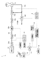
図1に示すように、燃料供給装置1は、燃料である水素(燃料ガス)が充填された水素タンク11と、この水素タンク11に接続される水素供給路12を主に備えている。この燃料供給装置1では、水素タンク11内の水素を水素供給路12を介して燃料電池(ガス機関)2に供給している。
【0017】
水素タンク11にはインタンク弁11aが設けられ、このインタンク弁11aの開閉により水素の供給やその供給の遮断が行われている。水素供給路12には、水素タンク11側から順に、第1のレギュレータ12b、遮断弁12a、第2のレギュレータ12cおよびエゼクタ12dがそれぞれ適所に設けられている。このエゼクタ12dには、燃料電池2内において発電に寄与しなかった未利用の水素を再利用するための循環路12eが接続されている。この循環路12eには、燃料電池2の運転状態を監視する図示しない監視手段からのパージ指令により開弁するパージ弁12fが設けられている。なお、このパージ弁12fは、燃料電池2の水素極側の状態をリフレッシュする目的で設けられており、たとえば、循環路12e内に燃料電池2の発電による生成水が溜まった場合などに開弁され、循環路12e内の水素とともに生成水を排出する。
【0018】
そして、水素供給路12におけるインタンク弁11aと第1のレギュレータ12bの間には、その内部の水素の圧力(圧力降下量)P1および温度T1を常時検出する第1のセンサ(圧力降下量検出手段)3が設けられている。また、この水素供給路12におけるエゼクタ12dと燃料電池2の間には、その内部の圧力P2および温度T2を常時検出する第2のセンサ4が設けられている。さらに、循環路12eのパージ弁12fには、その開放時間を検出する第3のセンサ5が設けられている。ちなみに、インタンク弁11aが開いている状態では、第1のセンサ3が検出する圧力は、水素タンク11の内部の圧力と同じである。
【0019】
一方、アクセルペダルAPには、その踏み込み量に相当するアクセル開度を検出する開度センサ6が設けられている。この開度センサ6は、アクセル開度に基づく指令値を燃料電池2に送信して、この燃料電池2から所定量の電流を発生させている。そして、この開度センサ6および前記第1〜3のセンサ3〜5はECU(制御マイコン)7に接続されている。このECU7には、その内部に水素漏れ判断手段71がプログラムとして組み込まれているとともに、その外部の接続端子に警報ブザーや警報ランプ等の報知手段8が接続されている。なお、本実施形態における「圧力降下量算出手段」は、第1〜第3のセンサ3〜5、アクセルペダルAPの開度センサ6およびECU7によって構成されている。
【0020】
ECU7の水素漏れ判断手段71は、図2に示すように、発電量設定手段71a、消費水素量設定手段71b、パージ水素量設定手段71c、減耗水素量設定手段71d、総水素量算出手段71e、密度補正値設定手段71f、圧力降下量算出手段71g,71h、漏れ判定手段71iを含んで構成される。なお、本実施形態では、水素漏れ判断手段71をECU7の内部で機能するプログラムとして構成されるものとしたが、ハードウェア的に構成されていてもよいのはいうまでもない。
【0021】
以下、水素漏れ判断手段71の各構成を説明する。
発電量設定手段71aは、開度センサ6からの指令値を入力して、燃料電池2の発電量を設定する。このため、この発電量設定手段71aは、指令値から発電量を設定するマップを有する。
【0022】
消費水素量設定手段71bは、発電量設定手段71aで設定した発電量を入力して、燃料電池2により消費した消費水素量を設定する。このため、この消費水素量設定手段71bは、発電量から消費水素量を設定するマップを有する。
【0023】
パージ水素量設定手段71cは、第3のセンサ5が検出したパージ弁12fの開弁時間と、第2のセンサ4が検出した圧力P2および温度T2を入力して、外部にパージされたパージ水素量を設定する。このため、このパージ水素量設定手段71cは、開弁時間、圧力P2および温度T2からパージ水素量を設定するマップを有する。つまり、本実施形態では、パージされた水素量を、第2のセンサ4で検出された循環路12e内の圧力P2および温度T2によって密度補正している。そうすることによってより正確に未利用の水素量を設定することが可能になり、後記する漏れ判定手段71iの判定精度が向上する。
【0024】
減耗水素量設定手段71dは、第2のセンサ4が検出した圧力P2と温度T2を入力して、前記消費水素量およびパージ水素量以外に減耗した減耗水素量を設定する。このため、この減耗水素量設定手段71dは、圧力P2と温度T2から減耗水素量を設定するマップを有する。つまり、本実施形態では、この減耗水素量を、第2のセンサ4で検出された循環路12e内の圧力P2および温度T2によって密度補正している。そうすることによってより正確に未利用の水素量を設定することが可能になり、後記する漏れ判定手段71iの判定精度が向上する。
【0025】
ここで、減耗水素量としては、複数のセルが積層(スタック)された燃料電池の場合では各セルの隙間から漏れ出す水素などが挙げられる。その場合の減耗水素量は、圧力が高くなると増え、温度が高くなると減る傾向にある。ちなみに、燃料電池は、電解質膜を水素極と酸素極とで挟み込んだ膜電極構造体(MEA)を、金属製のセパレータで仕切りながら積層した構造を有する。
なお、燃料電池2の通常運転時では、消費水素量、パージ水素量、減耗水素量および燃料電池2へ供給される供給水素量(総水素量)の関係は、次の通りである。
<供給水素量>=<消費水素量>+<パージ水素量>+<減耗水素量>
【0026】
総水素量算出手段71eは、前記消費水素量設定手段71b、パージ水素量設定手段71cおよび減耗水素量設定手段71dで設定された消費水素量、パージ水素量および減耗水素量を加算して総水素量を算出する。このため、この総水素量算出手段71eは、消費水素量、パージ水素量および減耗水素量を加算する加算機能を有する。
【0027】
密度補正値設定手段71fは、第1のセンサ3が検出した温度T1と圧力P1を入力して、理想気体として算出された前記総水素量を実在気体としての量に近づけるための密度補正値を設定する。このため、この密度補正値設定手段71fは、温度T1と圧力P1から密度補正値を設定するマップを有する。
【0028】
圧力降下量算出手段71gは、前記密度補正値と総水素量に基づいて、水素供給路12内の圧力が所定時間の間に降下する量を示す圧力降下量を算出する。ここで、この算出された圧力降下量は、燃料電池2に供給される水素が水素タンク11から水素供給路12を漏れずに通ってきたときのインタンク弁11aと第1のレギュレータ12bの間の圧力降下量(計算上の圧力降下量、以下、「算出された圧力降下量」ともいう)を表わしている。これに対して、圧力降下量算出手段71hは、第1のセンサ3が検出した圧力P1に基づいて、インタンク弁11aと第1のレギュレータ12bの間の実際の圧力降下量(以下、「検出された圧力降下量」ともいう)を算出する。
【0029】
漏れ判定手段71iは、前記検出された圧力降下量と算出された圧力降下量を入力して、この検出された圧力降下量が算出された圧力降下量よりも所定値以上大きければ、すなわち、検出された圧力降下量と算出された圧力降下量の差が所定値以上であれば水素が漏れていると判定して、警報信号を出力する。言い換えると、この漏れ判定手段71iは、図3に示すように、消費水素量、パージ水素量および減耗水素量から推定される水素タンク11内に残った水素量に誤差等を考慮した所定値を減算した量よりも、実際に水素タンク11内に残った水素量が少なければ、水素漏れがあったと判定して、警報信号を出力する。このため、この漏れ判定手段71iは、検出された圧力降下量と算出された圧力降下量の差を所定値と比較して水素漏れを判断する比較判断機能を有するとともに、報知手段8を作動するための警報信号を生成する機能を有する。なお、水素漏れを判断するための前記所定値は、漏れを検出するための閾値、あるいは不感帯の意義を有する。この所定値は、システムボリューム等を考慮した実験値や理論計算値から定められる。ここで、この所定値を小さくすれば少量の水素漏れを検出することができ、大きくすれば誤報知を防止することができる。
【0030】
次に、燃料供給装置1の動作について説明する。
まず、図1に示すように、インタンク弁11aと遮断弁12aを開放させて、水素タンク11から水素を放出させる。この水素タンク11から送られる水素は、第1,2のレギュレータ12b,12cにより適正な圧力に減圧され、エゼクタ12dを介して燃料電池2に供給される。この燃料電池2は、その発電により出力される電流を電動機Mに供給する。そして、この燃料電池2の発電で消費されなかった水素は、循環路12eを通ってエゼクタ12dに戻される。この循環路12eに設けられたパージ弁12fは、監視手段からのパージ指令により開放されて水素を外部へパージさせ、循環路12e内の圧力が所定値となったら閉鎖される。このように、水素タンク11から燃料電池2へ水素が供給されている間、第1〜3のセンサ3〜5および開度センサ6で検出された検出値がECU7に常時送られている。
【0031】
ECU7では、図2に示すように、開度センサ6から送信される指令値に基づいて発電量設定手段71aが燃料電池の発電量を設定し、この発電量に基づいて消費水素量設定手段71bが消費水素量を設定する。第3のセンサ5から送信されるパージ弁12fの開放時間と第2のセンサ4から送信される圧力P2および温度T2に基づいてパージ水素量設定手段71cがパージ水素量を設定する。第2のセンサ4から送信される圧力P2および温度T2に基づいて減耗水素量設定手段71dが減耗水素量を設定する。そして、前記消費水素量と、燃料電池から排出された未利用の水素量であるパージ水素量および減耗水素量とが総水素量算出手段71eにより加算され、総水素量が算出される。
【0032】
第1のセンサ3から送信される圧力P1および温度T1に基づいて、すなわち水素の状態に応じて、密度補正値設定手段71fが密度補正値を設定する。この密度補正値は、第1のセンサ3で検出された圧力P1が高いほど前記総水素量を大きく補正する値になり、その温度T1が低いほど前記総水素量を小さく補正する値になる。そして、この密度補正値と前記総水素量とに基づいて、圧力降下量算出手段71gが圧力降下量を算出する。一方、第1のセンサ3から送信される圧力P1に基づいて、圧力降下量算出手段71hが実際の圧力降下量を算出する。
【0033】
このように、圧力降下量算出手段71gにより算出された圧力降下量と圧力降下量算出手段71hにより算出された実際の圧力降下量(検出された圧力降下量)は、漏れ判定手段71iにより比較される。そして、検出された圧力降下量と算出された圧力降下量との差が所定値以上であれば、漏れ判定手段71iは水素が漏れていると判定する。
【0034】
このように、ECU7の水素漏れ判断手段71(漏れ判定手段71i)により水素が漏れていると判断した場合は、図1に示すように、その信号が報知手段8に送られて、この報知手段8により水素が漏れていることが報知される。さらに、ECU7によりインタンク弁11aと遮断弁12aに水素の供給を遮断させる水素遮断信号が送られて、これらの弁11a,12aが閉じられる。
【0035】
以上によれば、本実施形態において、次のような効果を得ることができる。
算出された圧力降下量、すなわち水素が水素供給路12を漏れずに通ってきたときの値を表わす圧力降下量と実際の値を示す検出された圧力降下量を比較するので、検出された圧力降下量と算出された圧力降下量との差が所定値以上である場合に水素が漏れていると判断することができる。また、このように燃料電池2の総水素量から算出した圧力降下量と実際の圧力降下量を比較することにより、従来のように弁を閉じるための設定値を燃料電池の最大消費量に対応する圧力降下量等よりも高めに設定する必要がないので、わずかな水素漏れを精度良く検知することができる。
【0036】
以上、本発明は、前記実施形態に限定されることなく、様々な形態で実施される。
本実施形態では、燃料電池2の消費水素量を設定するために、開度センサ6による指令値を利用する構造としたが、本発明はこれに限定されるものではない。たとえば、燃料電池から取り出される電流値および電圧値をセンサにより検出して、この検出値に基づいて燃料電池の消費水素量を算出するようにしてもよい。本実施形態では、パージ水素量を第3のセンサ5で検出したパージ弁12fの開放時間に基づいて算出するようにしたが、本発明はこれに限定されるもではない。たとえば、パージ水素量を、パージ指令時に所定時間パージ弁を開放するといったパージ指令値に基づいて算出してもよく、パージ弁から排出される水素量を直接検出して、その検出値に基づいて算出してもよい。
本実施形態では、燃料電池から排出されるパージ水素量および減耗水素量を用いて総水素量を算出しているが、本発明はこれに限定されず、たとえば、パージ水素、減耗水素のどちらかが微量で無視できる場合はどちらか片方の未利用水素量を用いて総水素量を算出してもよい。
【0037】
【発明の効果】
請求項1に記載の発明によれば、算出された圧力降下量と実際の値を示す検出された圧力降下量を比較することで、従来のように弁を閉じるための設定値を燃料電池の最大消費量に対応する流量もしくは圧力降下量よりも高めに設定する必要がないので、わずかな水素漏れを精度良く検知することができる。
【0038】
請求項1に記載の発明によれば、たとえば、未利用の水素量を燃料電池内の減耗水素量とパージ水素量に分けて算出するため、わずかな水素漏れをより精度良く検知することができる。
【0039】
請求項2に記載の発明によれば、請求項1に記載の発明による効果に加え、たとえば、総水素量が水素供給路内の水素の圧力と温度に応じて補正されるので、わずかな水素漏れをより精度良く検知することができる。
【図面の簡単な説明】
【図1】本実施形態に係る燃料供給装置の構成を示す構成図である。
【図2】本実施形態に係る水素漏れ判断手段を示すブロック図である。
【図3】本実施形態に係る漏れ判定手段の判定方法の概念を示す概念図である。
【符号の説明】
1 燃料供給装置
11 水素タンク
12 水素供給路
2 燃料電池
3 第1のセンサ(圧力降下量検出手段)
4 第2のセンサ
5 第3のセンサ
6 開度センサ
7 ECU
71 水素漏れ判断手段[0001]
BACKGROUND OF THE INVENTION
The present invention relates to a fuel supply device that supplies fuel gas, and more particularly to a fuel supply device that includes means for detecting leakage of fuel gas.
[0002]
[Prior art]
Conventionally, a vehicle driven by a fuel gas such as hydrogen or compressed natural gas mainly has a tank for storing the fuel gas and a fuel supply pipe for supplying the fuel gas from the tank to a fuel cell, an engine, or the like. The fuel supply apparatus comprised is provided. Such a fuel supply apparatus is provided with an overflow prevention valve that shuts off the fuel supply pipe when gas leaks as a countermeasure against gas leakage. Specifically, this overflow prevention valve is provided with a shut-off mechanism that closes the fuel supply pipe when an excessive flow rate flows using the increase in the flow rate of the gas flowing through the fuel supply pipe as the gas leaks. It has a structure.
As another gas leakage countermeasure, there is a fuel supply device that includes a pressure sensor that detects the pressure of the fuel gas flowing through the fuel supply pipe, and a shutoff valve that shuts off the supply of the fuel gas based on the detected value of the pressure sensor. . Specifically, in this fuel supply device, when the pressure of the fuel gas flowing through the fuel supply pipe is constantly detected by a pressure sensor, and the amount of pressure drop calculated from this detected value is equal to or greater than a predetermined pressure drop amount, the shut-off valve It has a structure that can be closed.
[0003]
[Problems to be solved by the invention]
However, in the conventional structure with an overflow prevention valve, the set flow rate for closing the overflow prevention valve is set to the maximum consumption of a gas engine such as a fuel cell so that the overflow prevention valve does not operate during normal operation. Since it was set higher than this, it was difficult to detect a slight gas leak, and the shut-off mechanism sometimes did not operate.
In addition, in a structure with a pressure sensor that detects the pressure of the fuel gas flowing through the fuel supply pipe and a shutoff valve that shuts off the fuel gas supply based on the detected value of the pressure sensor, the shutoff valve operates during normal operation. Therefore, it was difficult to detect a slight gas leak because the set pressure drop for closing the shut-off valve was set higher than the pressure drop corresponding to the maximum consumption of fuel cells. It was.
In order to detect this slight gas leak, there is a method of providing a sensor at the place where gas leak is expected, but this method is sensitive to the temperature of the external air, etc. It was difficult to detect well.
[0004]
Therefore, an object of the present invention is to provide a fuel supply device that can accurately detect a slight gas leak.
[0005]
[Means for Solving the Problems]
The hydrogen supply device according to
[0006]
According to the first aspect of the present invention, the pressure drop amount calculation means calculates the amount of unused hydrogen discharged from the fuel cell and the total amount of hydrogen corresponding to the sum of the amount of hydrogen consumed by the fuel cell from the total hydrogen amount in the hydrogen supply path. The amount of pressure drop is calculated. On the other hand, the actual pressure drop amount in the hydrogen supply path is detected by the pressure drop amount detecting means. Then, when the actual pressure drop detected by the pressure drop detecting means is larger than the pressure drop calculated by the pressure drop calculating means by a predetermined value or more by the hydrogen leak judging means, it is determined that hydrogen is leaking. Is done. When it is determined by the hydrogen leak determination means that hydrogen is leaking, for example, the hydrogen leak is notified by the notification means, and the supply of hydrogen from the hydrogen tank is shut off by closing the shutoff valve.
In addition, since the amount of unused hydrogen is calculated separately for the amount of depleted hydrogen and the amount of purge hydrogen in the fuel cell, a slight hydrogen leak can be detected with higher accuracy.
[0009]
According to a second aspect of the present invention, in the configuration of the first aspect of the present invention, there is provided correction means for correcting the total hydrogen amount according to the state of hydrogen in the hydrogen supply path.
[0010]
According to the invention described in claim 2 , in addition to the operation of the invention described in
[0015]
DETAILED DESCRIPTION OF THE INVENTION
Hereinafter, the details of the fuel supply device according to the present invention will be described with reference to the drawings. In this embodiment, the present invention is applied to a fuel supply device that supplies hydrogen to a fuel cell.
[0016]
As shown in FIG. 1, the
[0017]
The
[0018]
And between the in-
[0019]
On the other hand, the accelerator pedal AP is provided with an opening sensor 6 for detecting an accelerator opening corresponding to the depression amount. The opening sensor 6 transmits a command value based on the accelerator opening to the fuel cell 2 to generate a predetermined amount of current from the fuel cell 2. The opening sensor 6 and the first to
[0020]
As shown in FIG. 2, the hydrogen leak determination means 71 of the
[0021]
Hereinafter, each structure of the hydrogen leak judgment means 71 is demonstrated.
The power generation amount setting means 71 a inputs the command value from the opening sensor 6 and sets the power generation amount of the fuel cell 2. For this reason, this power generation amount setting means 71a has a map for setting the power generation amount from the command value.
[0022]
The hydrogen consumption amount setting means 71b inputs the power generation amount set by the power generation amount setting means 71a, and sets the hydrogen consumption amount consumed by the fuel cell 2. For this reason, this hydrogen consumption amount setting means 71b has a map for setting the hydrogen consumption amount from the power generation amount.
[0023]
The purge hydrogen amount setting means 71c receives the
[0024]
The depleted hydrogen amount setting means 71d inputs the pressure P2 and temperature T2 detected by the second sensor 4, and sets the depleted hydrogen amount other than the consumed hydrogen amount and purge hydrogen amount. For this reason, this depleted hydrogen amount setting means 71d has a map for setting the depleted hydrogen amount from the pressure P2 and the temperature T2. That is, in this embodiment, the amount of depleted hydrogen is density-corrected by the pressure P2 and the temperature T2 in the
[0025]
Here, as the amount of depleted hydrogen, in the case of a fuel cell in which a plurality of cells are stacked, hydrogen leaking out from the gaps between the cells can be used. In this case, the amount of depleted hydrogen tends to increase as the pressure increases and decrease as the temperature increases. Incidentally, the fuel cell has a structure in which a membrane electrode structure (MEA) in which an electrolyte membrane is sandwiched between a hydrogen electrode and an oxygen electrode is stacked while being partitioned by a metal separator.
During normal operation of the fuel cell 2, the relationship among the amount of hydrogen consumed, the amount of purge hydrogen, the amount of depleted hydrogen, and the amount of hydrogen supplied to the fuel cell 2 (total hydrogen amount) is as follows.
<Supply hydrogen amount> = <Consumption hydrogen amount> + <Purge hydrogen amount> + <Depleted hydrogen amount>
[0026]
The total hydrogen
[0027]
The density correction value setting means 71f receives the temperature T1 and pressure P1 detected by the
[0028]
Based on the density correction value and the total hydrogen amount, the pressure drop
[0029]
The leak determination means 71i inputs the detected pressure drop amount and the calculated pressure drop amount, and if this detected pressure drop amount is larger than the calculated pressure drop amount by a predetermined value or more, that is, detects If the difference between the calculated pressure drop amount and the calculated pressure drop amount is equal to or greater than a predetermined value, it is determined that hydrogen is leaking, and an alarm signal is output. In other words, as shown in FIG. 3, the leak determination means 71i sets a predetermined value in consideration of errors and the like in the hydrogen amount remaining in the
[0030]
Next, the operation of the
First, as shown in FIG. 1, the in-
[0031]
In the
[0032]
Based on the pressure P1 and temperature T1 transmitted from the
[0033]
In this way, the pressure drop amount calculated by the pressure drop amount calculating means 71g and the actual pressure drop amount (detected pressure drop amount) calculated by the pressure drop amount calculating means 71h are compared by the
[0034]
Thus, when it is judged by the hydrogen leak judgment means 71 (leak judgment means 71i) of ECU7 that hydrogen is leaking, the signal is sent to the notification means 8, as shown in FIG. 8 indicates that hydrogen is leaking. Further, the
[0035]
According to the above, the following effects can be obtained in the present embodiment.
Since the calculated pressure drop, that is, the pressure drop representing the value when hydrogen passes through the
[0036]
As mentioned above, this invention is implemented in various forms, without being limited to the said embodiment.
In the present embodiment, in order to set the amount of hydrogen consumption of the fuel cell 2, the command value from the opening sensor 6 is used. However, the present invention is not limited to this. For example, a current value and a voltage value taken out from the fuel cell may be detected by a sensor, and the hydrogen consumption amount of the fuel cell may be calculated based on the detected value. In the present embodiment, the purge hydrogen amount is calculated based on the opening time of the
In this embodiment, the total hydrogen amount is calculated using the purge hydrogen amount and the depleted hydrogen amount discharged from the fuel cell. However, the present invention is not limited to this, for example, either purge hydrogen or depleted hydrogen. May be negligible and negligible, the total hydrogen amount may be calculated using one of the unused hydrogen amounts.
[0037]
【The invention's effect】
According to the first aspect of the present invention, by comparing the calculated pressure drop amount with the detected pressure drop amount indicating the actual value, the set value for closing the valve as in the conventional case is set. Since it is not necessary to set higher than the flow rate or pressure drop corresponding to the maximum consumption, a slight hydrogen leak can be accurately detected.
[0038]
According to the invention described in
[0039]
According to the invention described in claim 2 , in addition to the effect of the invention described in
[Brief description of the drawings]
FIG. 1 is a configuration diagram showing a configuration of a fuel supply device according to an embodiment.
FIG. 2 is a block diagram showing hydrogen leak determination means according to the present embodiment.
FIG. 3 is a conceptual diagram illustrating a concept of a determination method of a leak determination unit according to the present embodiment.
[Explanation of symbols]
DESCRIPTION OF
4
71 Hydrogen leak judgment means
Claims (2)
この水素タンクから水素を水素供給路を介して燃料電池に供給する燃料供給装置において、
前記燃料電池から排出された水素を前記水素供給路に戻す循環路と、
前記循環路に設けられたパージ弁と、
前記燃料電池から排出された未利用の水素量である前記燃料電池内での減耗水素量および前記パージ弁を開放してパージされるパージ水素量と、前記燃料電池の発電により消費した水素量の和に相当する総水素量から前記水素供給路内の圧力降下量を算出する圧力降下量算出手段と、
前記水素供給路内の圧力降下量を検出する圧力降下量検出手段と、
検出された圧力降下量が前記算出された圧力降下量よりも所定値以上大きいときは前記水素が漏れていると判断する水素漏れ判断手段と、
前記循環路内に設置され、圧力および温度を検出するセンサと、前記パージ弁の開放時間を検出するセンサと、をさらに備え、
前記パージ水素量は、前記パージ弁の開放時間と、前記圧力および温度とに基づいて算出し、
前記減耗水素量は、前記圧力および温度に基づいて算出することを特徴とする燃料供給装置。A hydrogen tank filled with hydrogen,
In the fuel supply device that supplies hydrogen from the hydrogen tank to the fuel cell via the hydrogen supply path,
A circulation path for returning hydrogen discharged from the fuel cell to the hydrogen supply path;
A purge valve provided in the circulation path;
The amount of depleted hydrogen in the fuel cell, which is the amount of unused hydrogen discharged from the fuel cell, the amount of purge hydrogen purged by opening the purge valve, and the amount of hydrogen consumed by power generation of the fuel cell A pressure drop amount calculating means for calculating a pressure drop amount in the hydrogen supply path from a total hydrogen amount corresponding to the sum;
Pressure drop amount detecting means for detecting a pressure drop amount in the hydrogen supply path;
Hydrogen leakage determination means for determining that the hydrogen is leaking when the detected pressure drop amount is larger than the calculated pressure drop amount by a predetermined value or more;
A sensor installed in the circulation path for detecting pressure and temperature, and a sensor for detecting the opening time of the purge valve;
The purge hydrogen amount is calculated based on the purge valve opening time and the pressure and temperature,
The depleted hydrogen amount is calculated based on the pressure and temperature.
Priority Applications (1)
| Application Number | Priority Date | Filing Date | Title |
|---|---|---|---|
| JP2001348187A JP4033376B2 (en) | 2001-11-14 | 2001-11-14 | Fuel supply device |
Applications Claiming Priority (1)
| Application Number | Priority Date | Filing Date | Title |
|---|---|---|---|
| JP2001348187A JP4033376B2 (en) | 2001-11-14 | 2001-11-14 | Fuel supply device |
Publications (3)
| Publication Number | Publication Date |
|---|---|
| JP2003148252A JP2003148252A (en) | 2003-05-21 |
| JP2003148252A5 JP2003148252A5 (en) | 2005-06-09 |
| JP4033376B2 true JP4033376B2 (en) | 2008-01-16 |
Family
ID=19161053
Family Applications (1)
| Application Number | Title | Priority Date | Filing Date |
|---|---|---|---|
| JP2001348187A Expired - Fee Related JP4033376B2 (en) | 2001-11-14 | 2001-11-14 | Fuel supply device |
Country Status (1)
| Country | Link |
|---|---|
| JP (1) | JP4033376B2 (en) |
Cited By (1)
| Publication number | Priority date | Publication date | Assignee | Title |
|---|---|---|---|---|
| KR101054046B1 (en) * | 2008-11-27 | 2011-08-03 | 주식회사 케피코 | How to check and handle the leakage of Elpia's vehicle |
Families Citing this family (16)
| Publication number | Priority date | Publication date | Assignee | Title |
|---|---|---|---|---|
| CN100449839C (en) | 2004-03-17 | 2009-01-07 | 丰田自动车株式会社 | Device and method for detecting gas leakage |
| JP4730646B2 (en) * | 2004-09-16 | 2011-07-20 | トヨタ自動車株式会社 | Fuel cell system |
| WO2006033426A1 (en) * | 2004-09-21 | 2006-03-30 | Toyota Jidosha Kabushiki Kaisha | Fuel cell system, abnormality detection method for the system, and movable body |
| JP2006108024A (en) * | 2004-10-08 | 2006-04-20 | Toyota Motor Corp | High pressure gas feeder and fuel cell system using it |
| JP4730064B2 (en) * | 2004-11-29 | 2011-07-20 | トヨタ自動車株式会社 | Gas leak detection device and fuel cell system |
| JP5151010B2 (en) * | 2005-04-05 | 2013-02-27 | トヨタ自動車株式会社 | Fuel cell system and gas leak detection method of the fuel cell system |
| JP5013037B2 (en) | 2005-07-01 | 2012-08-29 | トヨタ自動車株式会社 | FUEL CELL SYSTEM, ITS GAS LEAK DETECTION METHOD, AND MOBILE BODY |
| JP4806989B2 (en) | 2005-07-27 | 2011-11-02 | トヨタ自動車株式会社 | Fuel cell system |
| JP5011709B2 (en) * | 2005-11-10 | 2012-08-29 | 日産自動車株式会社 | Fuel cell system and hydrogen leak detection method for fuel cell system |
| JP4756465B2 (en) * | 2005-12-16 | 2011-08-24 | トヨタ自動車株式会社 | Fuel cell system and moving body |
| JP4378733B2 (en) | 2007-11-08 | 2009-12-09 | トヨタ自動車株式会社 | Fuel cell system and method for determining hydrogen leak in the system |
| US8668997B2 (en) | 2011-06-20 | 2014-03-11 | United Technologies Corporation | System and method for sensing and mitigating hydrogen evolution within a flow battery system |
| JP5957664B2 (en) * | 2012-05-25 | 2016-07-27 | 本田技研工業株式会社 | Fuel cell system and operation method thereof |
| KR101734649B1 (en) * | 2015-06-03 | 2017-05-11 | 현대자동차주식회사 | Method for calculating hydrogen comsumption amount of fuel cell vehicle |
| DE102017204202A1 (en) * | 2017-03-14 | 2018-09-20 | Robert Bosch Gmbh | Method for detecting a leak in an energy converter system |
| CN110657037B (en) * | 2019-09-29 | 2021-12-17 | 潍柴西港新能源动力有限公司 | Method for detecting leakage of gas supply system of natural gas engine |
-
2001
- 2001-11-14 JP JP2001348187A patent/JP4033376B2/en not_active Expired - Fee Related
Cited By (1)
| Publication number | Priority date | Publication date | Assignee | Title |
|---|---|---|---|---|
| KR101054046B1 (en) * | 2008-11-27 | 2011-08-03 | 주식회사 케피코 | How to check and handle the leakage of Elpia's vehicle |
Also Published As
| Publication number | Publication date |
|---|---|
| JP2003148252A (en) | 2003-05-21 |
Similar Documents
| Publication | Publication Date | Title |
|---|---|---|
| JP4033376B2 (en) | Fuel supply device | |
| KR101814876B1 (en) | Fuel cell system, vehicle and method of judging driving of opening/closing valve | |
| JP4806989B2 (en) | Fuel cell system | |
| US7882728B2 (en) | Dual anomaly judgment device for a fuel cell | |
| CA2632963C (en) | Fuel cell system, moving object equipped with fuel cell system, and abnormality judgment method for fuel cell system | |
| JP3783650B2 (en) | Gas fuel supply device | |
| KR20060124771A (en) | Fuel cell system and control method of same | |
| JP5099285B2 (en) | Fuel supply device | |
| JPWO2005010427A1 (en) | Gas supply device | |
| JP3572455B2 (en) | Fuel cell system | |
| KR20200042568A (en) | Fuel cell hydrogen supply fault diagnosis system and diagnosis method | |
| JP2005011703A (en) | Fuel cell system and gas leakage detection method | |
| KR20160057978A (en) | Fuel cell system | |
| WO2006048983A1 (en) | Fuel cell system | |
| WO2011067923A1 (en) | Power generation system | |
| KR20150072238A (en) | System and emergency control method for condensate drainage of fuel cell vehicle | |
| KR20200042278A (en) | Condensate water drain control system and control method for fuel cell | |
| KR101393581B1 (en) | Hydrogen leak detecting device and method of fuel cell system | |
| JP4202100B2 (en) | Function maintenance method of fuel cell system | |
| JP3783649B2 (en) | Vehicle fuel gas supply device | |
| KR101846628B1 (en) | Fuel cell system | |
| JP5199645B2 (en) | Fuel cell system | |
| KR20180095984A (en) | The method for detecting malfunction of the high pressure cylinder disposed in a fuel cell system | |
| JP2008256552A (en) | Gas leak detection method and gas distribution system | |
| JP2009037884A (en) | Fuel cell system |
Legal Events
| Date | Code | Title | Description |
|---|---|---|---|
| A521 | Written amendment |
Free format text: JAPANESE INTERMEDIATE CODE: A523 Effective date: 20040825 |
|
| A621 | Written request for application examination |
Free format text: JAPANESE INTERMEDIATE CODE: A621 Effective date: 20040825 |
|
| A131 | Notification of reasons for refusal |
Free format text: JAPANESE INTERMEDIATE CODE: A131 Effective date: 20070509 |
|
| A521 | Written amendment |
Free format text: JAPANESE INTERMEDIATE CODE: A523 Effective date: 20070705 |
|
| A131 | Notification of reasons for refusal |
Free format text: JAPANESE INTERMEDIATE CODE: A131 Effective date: 20070822 |
|
| A521 | Written amendment |
Free format text: JAPANESE INTERMEDIATE CODE: A523 Effective date: 20070918 |
|
| TRDD | Decision of grant or rejection written | ||
| A01 | Written decision to grant a patent or to grant a registration (utility model) |
Free format text: JAPANESE INTERMEDIATE CODE: A01 Effective date: 20071017 |
|
| A61 | First payment of annual fees (during grant procedure) |
Free format text: JAPANESE INTERMEDIATE CODE: A61 Effective date: 20071019 |
|
| FPAY | Renewal fee payment (event date is renewal date of database) |
Free format text: PAYMENT UNTIL: 20101102 Year of fee payment: 3 |
|
| R150 | Certificate of patent or registration of utility model |
Free format text: JAPANESE INTERMEDIATE CODE: R150 |
|
| FPAY | Renewal fee payment (event date is renewal date of database) |
Free format text: PAYMENT UNTIL: 20101102 Year of fee payment: 3 |
|
| FPAY | Renewal fee payment (event date is renewal date of database) |
Free format text: PAYMENT UNTIL: 20111102 Year of fee payment: 4 |
|
| FPAY | Renewal fee payment (event date is renewal date of database) |
Free format text: PAYMENT UNTIL: 20111102 Year of fee payment: 4 |
|
| FPAY | Renewal fee payment (event date is renewal date of database) |
Free format text: PAYMENT UNTIL: 20121102 Year of fee payment: 5 |
|
| FPAY | Renewal fee payment (event date is renewal date of database) |
Free format text: PAYMENT UNTIL: 20131102 Year of fee payment: 6 |
|
| LAPS | Cancellation because of no payment of annual fees |